EP2856552B1 - Machine et processus d'obtention de cellules pour batteries de stockage électrique et cellule pour batterie de stockage électrique - Google Patents
Machine et processus d'obtention de cellules pour batteries de stockage électrique et cellule pour batterie de stockage électrique Download PDFInfo
- Publication number
- EP2856552B1 EP2856552B1 EP13727972.5A EP13727972A EP2856552B1 EP 2856552 B1 EP2856552 B1 EP 2856552B1 EP 13727972 A EP13727972 A EP 13727972A EP 2856552 B1 EP2856552 B1 EP 2856552B1
- Authority
- EP
- European Patent Office
- Prior art keywords
- electrodes
- continuous strips
- continuous
- dielectric material
- strip
- Prior art date
- Legal status (The legal status is an assumption and is not a legal conclusion. Google has not performed a legal analysis and makes no representation as to the accuracy of the status listed.)
- Active
Links
Images


Classifications
-
- H—ELECTRICITY
- H01—ELECTRIC ELEMENTS
- H01M—PROCESSES OR MEANS, e.g. BATTERIES, FOR THE DIRECT CONVERSION OF CHEMICAL ENERGY INTO ELECTRICAL ENERGY
- H01M10/00—Secondary cells; Manufacture thereof
- H01M10/04—Construction or manufacture in general
- H01M10/0404—Machines for assembling batteries
-
- H—ELECTRICITY
- H01—ELECTRIC ELEMENTS
- H01M—PROCESSES OR MEANS, e.g. BATTERIES, FOR THE DIRECT CONVERSION OF CHEMICAL ENERGY INTO ELECTRICAL ENERGY
- H01M10/00—Secondary cells; Manufacture thereof
- H01M10/04—Construction or manufacture in general
- H01M10/0459—Cells or batteries with folded separator between plate-like electrodes
-
- H—ELECTRICITY
- H01—ELECTRIC ELEMENTS
- H01M—PROCESSES OR MEANS, e.g. BATTERIES, FOR THE DIRECT CONVERSION OF CHEMICAL ENERGY INTO ELECTRICAL ENERGY
- H01M10/00—Secondary cells; Manufacture thereof
- H01M10/05—Accumulators with non-aqueous electrolyte
- H01M10/058—Construction or manufacture
- H01M10/0583—Construction or manufacture of accumulators with folded construction elements except wound ones, i.e. folded positive or negative electrodes or separators, e.g. with "Z"-shaped electrodes or separators
-
- H—ELECTRICITY
- H01—ELECTRIC ELEMENTS
- H01M—PROCESSES OR MEANS, e.g. BATTERIES, FOR THE DIRECT CONVERSION OF CHEMICAL ENERGY INTO ELECTRICAL ENERGY
- H01M50/00—Constructional details or processes of manufacture of the non-active parts of electrochemical cells other than fuel cells, e.g. hybrid cells
- H01M50/40—Separators; Membranes; Diaphragms; Spacing elements inside cells
- H01M50/463—Separators, membranes or diaphragms characterised by their shape
- H01M50/466—U-shaped, bag-shaped or folded
-
- Y—GENERAL TAGGING OF NEW TECHNOLOGICAL DEVELOPMENTS; GENERAL TAGGING OF CROSS-SECTIONAL TECHNOLOGIES SPANNING OVER SEVERAL SECTIONS OF THE IPC; TECHNICAL SUBJECTS COVERED BY FORMER USPC CROSS-REFERENCE ART COLLECTIONS [XRACs] AND DIGESTS
- Y02—TECHNOLOGIES OR APPLICATIONS FOR MITIGATION OR ADAPTATION AGAINST CLIMATE CHANGE
- Y02E—REDUCTION OF GREENHOUSE GAS [GHG] EMISSIONS, RELATED TO ENERGY GENERATION, TRANSMISSION OR DISTRIBUTION
- Y02E60/00—Enabling technologies; Technologies with a potential or indirect contribution to GHG emissions mitigation
- Y02E60/10—Energy storage using batteries
-
- Y—GENERAL TAGGING OF NEW TECHNOLOGICAL DEVELOPMENTS; GENERAL TAGGING OF CROSS-SECTIONAL TECHNOLOGIES SPANNING OVER SEVERAL SECTIONS OF THE IPC; TECHNICAL SUBJECTS COVERED BY FORMER USPC CROSS-REFERENCE ART COLLECTIONS [XRACs] AND DIGESTS
- Y02—TECHNOLOGIES OR APPLICATIONS FOR MITIGATION OR ADAPTATION AGAINST CLIMATE CHANGE
- Y02P—CLIMATE CHANGE MITIGATION TECHNOLOGIES IN THE PRODUCTION OR PROCESSING OF GOODS
- Y02P70/00—Climate change mitigation technologies in the production process for final industrial or consumer products
- Y02P70/50—Manufacturing or production processes characterised by the final manufactured product
-
- Y—GENERAL TAGGING OF NEW TECHNOLOGICAL DEVELOPMENTS; GENERAL TAGGING OF CROSS-SECTIONAL TECHNOLOGIES SPANNING OVER SEVERAL SECTIONS OF THE IPC; TECHNICAL SUBJECTS COVERED BY FORMER USPC CROSS-REFERENCE ART COLLECTIONS [XRACs] AND DIGESTS
- Y10—TECHNICAL SUBJECTS COVERED BY FORMER USPC
- Y10T—TECHNICAL SUBJECTS COVERED BY FORMER US CLASSIFICATION
- Y10T29/00—Metal working
- Y10T29/53—Means to assemble or disassemble
- Y10T29/5313—Means to assemble electrical device
- Y10T29/53135—Storage cell or battery
- Y10T29/53139—Storage cell or battery including deforming means
Definitions
- the present invention regards a machine and a process for obtaining cells for electric storage batteries, as well as a cell for electric storage battery.
- the present machine and process are inserted in the industrial field of the production of electric storage batteries and are intended to be employed in the processes of production of cells for electric storage batteries in order to obtain stacks of positive and negative electrodes and arranged alternated with each other, with a dielectric separator interposed.
- a process for obtaining cells for electric storage batteries which provides for depositing, between the electrodes, separators formed by a single continuous strip of dielectric material, folded between the electrodes.
- a process of the latter type known for the production of cells for electric storage batteries, in particular for rechargeable lithium batteries, is for example described in the patent US 6,589,300 .
- the process described herein provides for drawing a continuous strip of dielectric material from a coil and simultaneously depositing, by means of spraying, an adhesive on both faces of the dielectric material, at circumscribed areas spaced from each other on each face of the dielectric material.
- the areas of the dielectric material coated by the adhesive are intended to receive negative electrodes on a first face of the dielectric material and positive electrodes on the second face of the dielectric material and they are arranged at an equal distance from each other on each face of the dielectric material strip.
- the process then provides for simultaneously fixing a positive electrode and a negative electrode on the respective faces of the dielectric material at the areas on which the adhesive was deposited, for laminating the strip of dielectric material carrying the positive and negative electrodes fixed, and folding the dielectric material strip with fixed electrodes, in a manner so as to form a stack of negative and positive electrodes alternated with each other, between which the separators are interposed alternately formed by portions of the continuous dielectric material strip comprised between the electrodes and fixed thereto and by portions of the continuous strip folded above the electrodes.
- the main drawback consists of the high costs for obtaining cells for electric storage batteries by means of such process, in particular due to the use of the adhesive for fixing the electrodes to the dielectric material.
- the machine for obtaining cells for electric storage batteries by means of the aforesaid process requires a frequent cleaning and maintenance, since the adhesive sprayed on the strip of dielectric material and transported by the latter can easily dirty the parts of the machine nearest to the adhesive spraying station.
- the cells for storage batteries obtained by means of such process in addition to having high production costs as reported above, can also have poor efficiency, due to the reduced permeability to the ionic flow of the separators that have the adhesive deposited on the faces thereof.
- the patent WO 2011/141852 describes a process and a machine for obtaining cells for electric storage batteries.
- the process described herein in particular provides for the arrangement of a continuous strip of dielectric material on which a plurality of positive and negative electrodes are arranged according to a pre-established sequence, spaced from each other.
- Such process provides that the dielectric material strip is wound around a first electrode in order to obtain a stack of alternated positive and negative electrodes, between which the separators are interposed that are defined by portions of a same continuous strip of dielectric material substantially wound as a spiral between the electrodes.
- the machine described herein comprises a device for winding the strip of dielectric material and forming the stack of electrodes and separators; such winding device comprises gripping means adapted to grasp the first electrode arranged on the dielectric material strip and adapted to rotate in order to wind the dielectric material strip supporting the remaining electrodes around the first electrode.
- a first drawback of the process consists of the fact that it is necessary to arrange the electrodes on the strip of dielectric material according to a precise pre-established sequence, so as to prevent the electrodes having the same polarity from being situated adjacent to each other at the end of the forming of the stack of electrodes and separators.
- a second drawback of the process lies in the fact that the electrodes must be arranged on the strip of dielectric material at a variable distance from each other and particularly at an increasing distance, in order to account for the fact that, as the winding continues, the thickness of the stack of electrodes increases and hence it is necessary to employ a greater quantity of dielectric material for winding the entire stack. It is therefore evident that the process described in the patent WO 2011/141852 is particularly difficult to carry out.
- the machine described in the aforesaid patent is structurally complex to obtain, in particular having to comprise rotating gripping means.
- zigzag stacking Also known in the present industrial field is a process for producing cells for electric storage batteries that is termed "zigzag stacking", which provides for depositing a first negative or positive electrode on a first end edge of a dielectric material strip, for folding the aforesaid strip to coat the first electrode, then for depositing a second electrode having opposite polarity with respect to the polarity of the first electrode and for newly folding the strip of dielectric material to coat the second electrode.
- Such operations are repeated until a stack of electrodes and separators is obtained having the desired number of electrodes, in which the separators are defined by portions of the same continuous strip of dielectric material, folded in a zigzag manner between the electrodes.
- WO2012/020480 1 discloses a positive and negative electrode plate stacking method and device, which allows to stack positive and negative electrode plates with high efficiency while keeping misalignment in the stacking of the positive and negative electrode plates to a minimum.
- the present application relates to a machine and a process for obtaining cells for electric storage batteries, and to a cell for electric storage batteries, as defined in the independent claims.
- the problem underlying the present invention is that of overcoming the drawbacks manifested by the processes, by the machines and by the cells for electric storage batteries of known type by providing a process for obtaining cells for electric storage batteries that have high efficiency.
- Another object of the present invention is to provide a process that allows obtaining cells for electric storage batteries in a quick and simple manner.
- a further object of the present invention is to provide a machine for obtaining cells for electric storage batteries, which allows obtaining stacks of electrodes and separators with high production capacity.
- Another object of the present invention is to provide a machine for obtaining cells for electric storage batteries, which is structurally simple, entirely reliable in operation and which requires little maintenance.
- a further object of the present invention is to provide a cell for electric storage battery which is provided with high efficiency and has low production costs.
- the cells made by this machine are advantageously intended to be employed in conventional processes for the formation of electric storage batteries and particularly for the formation of lithium storage batteries.
- Such processes generally comprise the obtainment of a plurality of cells, the connection in series or in parallel of multiple cells and the arrangement of the same in a protection casing, usually made of polymer material.
- cell With the term "cell” it must be intended a stack of positive and negative electrodes, in a desired number, arranged alternated and with a separator interposed between each pair of adjacent electrodes with opposite polarity.
- separatator it must be intended, in the scope of the present invention, the portion of a membrane of dielectric material arranged between two adjacent electrodes of opposite polarity, adapted to electrically separate the electrodes but permeable to the ionic flow.
- Each of the electrodes employed in obtaining cells for electric storage batteries according to the present invention is provided, in a per se known manner, with an electrical collector, e.g. in the form of a tongue projecting from one side of the main body of the electrode.
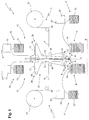
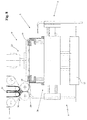
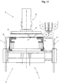
- the machine 1 is provided with a support structure 2 set on the ground, which supports a feeding apparatus 3 adapted to release one or more continuous strips 4 of dielectric material, a first and a second apparatus 5' and 5" for distributing electrodes and a folding head 6 provided with a stacking surface 7 susceptible to receive the continuous strip (or the continuous strips) 4 of dielectric material from the feeding apparatus 3.
- the folding head 6 is movable between a first position A, illustrated for example in Figures 1 , 2 , 7 , 8 and 12 , and a second position B, illustrated for example in Figures 1 , 2 and 11 , translated with respect to the first position A along a direction X orthogonal to the lying plane ⁇ of the continuous strip (or of the continuous strips) 4 of dielectric material released from the feeding apparatus 3 in order to obtain, by being moved from the position A to the position B and vice versa, a plurality of layers with the electrodes interposed that were deposited by the first and by the second distribution apparatus 5' and 5".
- the feeding apparatus 3 is adapted to release, on the folding head 6, two continuous strips 4 of dielectric material and comprises coupling means 8 for coupling the two continuous strips 4 in their extension, along respective opposite internal faces 9 thereof.
- first distribution apparatus 5' and the second distribution apparatus 5" are adapted to distribute first electrodes 10 having the same polarity.
- the machine 1 comprises a third distribution apparatus 11 of second electrodes 12 having opposite polarity with respect to the polarity of the first electrodes 10, such third distribution apparatus 11 adapted to transfer the second electrodes 12 to the coupling means 8 of the feeding apparatus 3, introducing them between the internal faces 9 of the two continuous strips 4 of dielectric material.
- the second electrodes 12 are transferred to the coupling means 8 by the third distribution apparatus 11 spaced from each other, so as to be spaced from each other along the preferred extension direction Z of the two continuous strips 4.
- the feeding apparatus 3 is then adapted to release, towards the folding head 6, the pair of continuous strips 4 with the second electrodes 12 spaced from each other interposed.
- the pair of continuous strips 4 is released towards the folding head 6 by the coupling means 8 of the feeding apparatus 3, in particular through an emission mouth 59 thereof.
- the pair of continuous strips 4 with the second electrodes 12 interposed is indicated with the number 13 in its entirety.
- the pair 13 of continuous strips 4 is referred to hereinbelow, it is intended to indicated the set formed by the two continuous strips 4 bearing, interposed between the internal faces 9 thereof, the second electrodes 12 that are spaced from each other.
- the folding head 6 is adapted to receive, from the feeding apparatus 3, a composite layer 14 formed by a section of the pair 13 of continuous strips 4 containing one of the second electrodes 12, interposed between the two continuous strips 4, with each passage between the first and the second position A and B, i.e. each time it moves from the first position A to the second position B and vice versa, forming a fold 45 between two consecutive composite layers 14.
- the folding head 6 is adapted to receive a first electrode 10 from the first distribution apparatus 5', when it is situated in the first position A, on the composite layer 14 received from the feeding apparatus 3 being moved from the second position B to the first position A, as illustrated in figure 8 , and it is adapted to receive a first electrode 10 from the second distribution apparatus 5", when it is situated in the second position B, on the composite layer 14 received from the feeding apparatus 3 being moved from the first position A to the second position B, as illustrated in figure 11 , in order to form a stack on the stacking surface 7 composed of the composite layers 14 alternated with the first electrodes 10.
- the pair 13 of continuous strips 4 with the second electrodes 12 interposed that is released by the coupling means 8 is arranged on the stacking surface 7 in a plurality of composite layers 14, each formed by a section of the pair 13 of strips containing a second electrode 12, substantially folded as a zigzag on each other and with the first electrodes 10 interposed.
- the machine 1 is thus adapted to form on the folding head 6, and in particular on the stacking surface 7 thereof, a stack of first electrodes 10 and second electrodes 12 alternated with each other, with the two continuous strips 4 of dielectric material, comprising the second electrodes 12 between them, each alternately defining two consecutive separators 24, as is clearly visible in figure 14d .
- the lying plane ⁇ of the pair 13 of continuous strips 4 released by the coupling means 8 is substantially vertical and the folding head 6 is arranged below the coupling means 8 in order to receive therefrom the pair 13 of continuous strips 4 on its substantially horizontal stacking surface 7.
- the first and the second position A and B, between which the folding head 6 is movable, are advantageously arranged symmetric to the lying plane ⁇ of the pair 13 of continuous strips 4 released by the coupling means 8, as illustrated in Figures 1 and 2 .
- the folding head 6 is intended to receive, from the coupling means 8, the first of the composite layers 14 directly on the stacking surface 7, whereas it is intended to receive the subsequent composite layers 14 on the stack of electrodes and separators being formed on the stacking surface 7 thereof, i.e. particularly on the last of the first electrodes 10 that was deposited on the stack being formed by the first or by the second distribution apparatus 5' or 5".
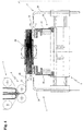
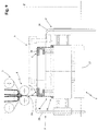
- the folding head 6 comprises a trolley 17 susceptible to slide, guided by a horizontal guide 16, on a base 15 fixed to the support structure 2, in order to move the folding head 6 between the first position A and the second position B.
- the trolley 17 is actuated to slide on the guide 16 by actuation means, such as an electric motor (not shown).
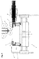
- the folding head 6 also comprises a stacking portion 58, comprising the stacking surface 7, which is mounted on the trolley 17 movable along a direction Z' parallel to the preferred extension direction Z of the two continuous strips 4 released from the feeding apparatus 3, between a receded position R, illustrated for example in figure 9 , in which it is moved away from the emission mouth 59 of the coupling means 8, and an advanced position S, illustrated for example in Figures 8 and 10 , in which it is brought close to the emission mouth 59 of the coupling means 8, along the direction Z'.
- a receded position R illustrated for example in figure 9
- an advanced position S illustrated for example in Figures 8 and 10
- the stacking portion 58 is arranged in the receded position R for at least one section of the travel of the trolley 17 between the first position A and the second position B, in order to maintain powered the pair 13 of continuous strips released by the coupling means 8 through the emission mouth 59, as will be better explained hereinbelow.
- the stacking portion 58 of the folding head 6 comprises two or more support columns 18 on which the stacking surface 7 is slidably mounted. More in detail, the stacking surface 7 is susceptible to be actuated to be lowered with respect to the support columns 18 in order to house, inside a volume delimited by the columns 18, the stack of electrodes and separators being formed on the stacking surface 7, as is for example visible in the enclosed figure 3 . Preferably, the stacking surface 7 is susceptible to being actuated to be progressively lowered with respect to the support columns 18 as the height of the stack being formed increases, in order to prevent the stack itself from interfering with the coupling means 8 when the head 6 is moved between the first and the second position A and B.
- the stacking surface 7 is susceptible to being actuated to be lifted with respect to the support columns 18 when the stack of electrodes and separators formed thereon has terminated and it is then drawn by the folding head 6, e.g. by means of an arm of a robot 48, as illustrated in figure 4 .
- the stacking surface 7 is controlled to be moved with respect to the columns 18 by means of actuation means (not shown), such as an electric motor.
- the folding head 6 also comprises two more folding blades 19, and preferably four folding blades 19, which are advantageously mounted on the stacking portion 58, preferably on two opposite sides thereof, and are extended parallel to the stacking surface 7 and orthogonal to the translation direction X of the folding head 6 between the first and the second position A and B. More in detail, a first pair of folding blades 19 mounted on two opposite sides of the stacking portion 58 is extended along a first preferred direction Y and a second pair of folding blades 19, also mounted on two opposite sides of the stacking portion 58, is extended along a second preferred direction Y', parallel to the first preferred direction Y.
- the pair of folding blades 19 are advantageously movable independent from each other and can be vertically translated along the preferred extension directions Y and Y' thereof between an interference position C and one or more non-interference positions D.
- the interference position C the folding blades 19 are superimposed on the stacking surface 7 and retain the stack of electrodes and separators being formed thereon when the folding head 6 is moved between the first position A and the second position B, preventing the composite layers 14 and the first electrodes 10 deposited on the folding head 6 from being moved.
- the front pair of folding blades 19, front with respect to the advancing direction of the folding head 6, is also placed in the interference position C when the head 6 is moved between the first position A and the second position B, in order to facilitate the formation of a fold on the pair 13 of continuous strips 4 that the coupling means 8 are releasing on the folding head 6, as illustrated in the enclosed Figures 9 and 10 .
- the folding blades 19 therefore allow simply and precisely obtaining a fold on the two continuous strips 4 of dielectric material and they also perform an action of mechanical blocking of the stack of electrodes and separators being formed, preventing the latter from being misaligned, in particular during the movement of the folding head 6.
- the blades 19 are moved away from the stacking surface 7, i.e. from the stack of electrodes and separators being formed thereon.
- the folding head 6 can also comprise two locking clamps 20, mounted on the stacking portion 58, preferably on the two opposite sides of the latter that do not carry the folding blades 19 mounted, such clamps adapted to assist the folding blades 19 in retaining the stack of electrodes and separators being formed on the folding head 6.
- the locking clamps 20 can be moved independently from each other and with respect to the folding blades 19, being adapted to translate vertically and along directions parallel to the translation direction X of the folding head 6, between an engagement position E and one or more non-engagement positions F.
- the locking clamps 20 are superimposed on the stacking surface 7 in abutment against the stack of electrodes and separators being formed thereon in order to retain the latter, and particularly for retaining in position the second electrode 12 comprised between the pair 13 of continuous strips 4 that the coupling means 8 are releasing on the folding head 6, as illustrated in figure 11 .
- the front locking clamp 20, front with respect to the advancing direction of the folding head 6, is advantageously brought in the engagement position E, preferably when the folding head 6 is situated about halfway between the position A and the position B.
- the non-engagement positions F the locking clamps 20 are moved away from the stacking surface 7, i.e. from the stack of electrodes and separators being formed thereon.
- the stacking portion 58 is actuated to be moved from the advanced position S to the receded position R along an initial section of the travel of the trolley 17 from the first position A to the second position B or vice versa, with the pair of front folding blades 19, front with respect to the advancing direction of the folding head 6 arranged in the interference position C, until such pair of front folding blades 19 substantially reaches the emission mouth 59 of the coupling means 8, i.e. it is substantially arranged below the latter. Subsequently, the stacking portion 58 is actuated to be newly moved towards the advanced position S and it then remains in the latter position until the trolley 17 has reached the second position B (or the first position A).
- the first and the second distribution apparatus 5' and 5" respectively comprise a first storage area 21' and a second storage area 21", which are mounted on the support structure 2 on the sides of the folding head 6.
- the first and the second distribution apparatus 5' and 5" also respectively comprise a first and a second transport device 22' and 22", adapted to draw the first electrodes 10 respectively from the first storage area 21' and from the second storage area 21" and to transfer them to the folding head 6.
- the first and the second storage area 21' and 21" are adapted to contain the first electrodes 10 stacked on each other, with the transport collectors for the current 43' arranged on the same side in both storage areas, as illustrated in figure 1 , such that all the first electrodes 10, drawn from the first storage area 21' or from the second storage area 21" and released on the folding head 6, i.e. on the stack of electrodes and separators being formed thereon, are arranged with the current transport collectors 43' aligned and arranged on the same side of the stack.
- each of the transport devices 22' and 22" is movable along a first horizontal guide 23 between a first (or second) draw position G' (or G"), in which it is arranged above the corresponding first (or second) storage area 21' (or 21") and collects therefrom a first electrode 10, and a first (or second) transfer position H' (or H"), in which it is arranged above the folding head 6 and transfers thereto the first electrode 10 previously collected from the storage area.
- the first and the second transport device 22' and 22" comprise first gripping means 25, such as a sucker or an aspirated plate, for selectively attracting thereto and retaining or releasing the first electrodes 10 when they are found in the first (or second) draw position G' (or G") and in the first (or second) transfer position H' (or H").
- first gripping means 25 such as a sucker or an aspirated plate
- the second transport device 22" when the first transport device 22' is situated in the first draw position G', the second transport device 22" is situated in the second transfer position H", and vice versa, such that the head 6 can be quickly moved between the first and the second position A and B in order to receive the first electrodes 10 alternately from the first and from the second transport device 22' and 22".
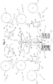
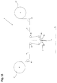
- the first and the second distribution apparatus 5' and 5" respectively comprise a first reel 55' and a second reel 55", as illustrated in figure 2 , each susceptible to support a winding respectively of a first continuous strip 56' and of a second continuous strip 56" of substrate material for electrodes.
- the first and the second continuous strip 56' and 56" are partially coated with an active coating for the formation of the first electrodes 10. More in detail, the active coating is coated in a continuous manner along the extension of the first and second continuous strip 56' and 56" of substrate material for electrodes, on a lateral portion of each of the latter. The portions of the first and of the second continuous strip 56' and 56" lacking the active coating are adapted to define the current transport collectors 43' of the first electrodes 10, as is visible in the representation in plan view of the first electrodes 10, reported in figure 2 .
- the first and the second distribution apparatus 5' and 5" also respectively comprise a first cutting device 57' and a second cutting device 57", susceptible to cut respectively the first and the second continuous strip 56' and 56" of substrate material for electrodes, partially coated with the active coating, in order to separate portions of the first and second continuous strip 56' and 56", each adapted to define the first electrodes 10.
- the first and the second distribution apparatus 5' and 5" in accordance with the final embodiment also respectively comprise a first transport device and a second transport device (not shown), susceptible to draw the first electrodes 10, respectively separated from the first and from the second continuous strip 56' and 56" of substrate material for electrodes and to release them on the folding head 6, when the latter is respectively situated in the first position A and in the second position B.
- the first and the second reel 55' and 55" are adapted to support the winding respectively of the first continuous strip 56' and of the second continuous strip 56" of substrate material for electrodes with the portions of the latter lacking the active coating arranged mirrored, such that all the first electrodes 10, separated from the continuous strips 56' and 56" and released on the folding head 6, i.e. on the stack of electrodes and separators being formed thereon, are arranged with the current transport collectors 43' arranged on a same side of the stack.
- the first and the second transport device of the first and second distribution apparatus 5' and 5" in accordance with the latter embodiment of the machine 1 in particular can be substantially of the type described previously.
- the third distribution apparatus 11 of the second electrodes 12 of the machine 1 in accordance with the present invention advantageously comprises means 26 for supplying the second electrodes 12 in succession and a device 27 for transferring the second electrodes 12, adapted to receive the second electrodes 12 from the supply means 26 and to transfer them, one after the other and equidistant from each other, to the coupling means 8 of the feeding apparatus 3, in order to insert them between the internal faces 9 of the two continuous strips 4 of dielectric material.
- the supply means 26 are adapted to transfer, to the transfer device 27, the second electrodes 12 in sheet form and the transfer device 27 comprises two first conveyor belts 28, each provided with a support portion 29 adapted to receive one of the second electrodes 12 in sheet form from the supply means 26, as will be better explained hereinbelow.
- the supply means 26 comprise one or more third storage areas 51, and preferably two third storage areas 51, for the containment of the second electrodes 12 in precut sheet form.
- the two third storage areas 51 are adapted to contain the second electrodes 12 stacked on each other, with the current transport collector 43" arranged on the same side in both the storage areas 51, as illustrated in figure 1 , such that the second electrodes 12 inserted between the two continuous strips 4 of dielectric material, as better specified below, are arranged with the current transport collectors 43" projecting all from a same side of the pair 13 of continuous strips 4.
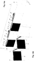
- each pair of adjacent second electrodes 12 along the extension of the continuous strips 4 is arranged with the electrical collectors 43" arranged mirrored, as illustrated in figure 14a .
- the third distribution apparatus 11 also comprises one or more third transport devices 30, and preferably two third transport devices 30, each adapted to draw the second electrodes 12 from a corresponding third storage area 51 and to transfer them to the transfer device 27.
- each of the third transport devices 30 is movable between a third (or fourth) draw position G"' (or G""), in which it is arranged above the corresponding third storage area 51 and collects therefrom a second electrode 12, and a third (or fourth) transfer position H"' (or H""), in which it is arranged above the support portion 29 of a corresponding conveyor belt 28 and transfers to the latter the second electrode 12 previously collected from the storage area.
- a third (or fourth) draw position G"' (or G"" in which it is arranged above the corresponding third storage area 51 and collects therefrom a second electrode 12
- a third (or fourth) transfer position H"' (or H"" in which it is arranged above the support portion 29 of a corresponding conveyor belt 28 and transfers to the latter the second electrode 12 previously collected from the storage area.
- the other third transport device 30 is situated in the third (or fourth) transfer position H"' (or H"" and vice versa, in order to quickly transfer the second electrodes 12 to the transfer device 27.
- each of the third transport devices 30 is movable between the third (or fourth) draw position G"' (or G"") and the third (or fourth) transfer position H"' (or H"") along a second horizontal guide 34, arranged substantially orthogonal to the first horizontal guide 23 of the first and second transport device 22' and 22",
- the third transport devices 30 each comprise second gripping means 35, such as a sucker or aspirated plate, for selectively attracting thereto and retaining or releasing the second electrodes 12 when they are situated respectively in the third (or fourth) draw position G"' (or G"") and in the third (or fourth) transfer position H"' (or H"").
- second gripping means 35 such as a sucker or aspirated plate
- the supply means 26 are adapted to transfer, to the transfer device 27, the second electrodes 12 in sheet form and they comprise one or more third reels 52 (preferably two third reels 52) each susceptible to support a winding of a continuous strip 53 of substrate material for electrodes, partially coated with an active coating for the formation of the second electrodes 12. More in detail, the active coating is deposited in a continuous manner along the extension of the third continuous strip 53 of substrate material for electrodes, on a lateral portion thereof. The portion of the third continuous strip 53 lacking the active coating is adapted to define the current transport collectors 43" of the second electrodes 12, as is visible in the plan view of the second electrodes 12 reported in figure 2 .
- the supply means 26 also comprise one or more third cutting devices 54, each susceptible to cut the continuous strip 53 of substrate material for electrodes of a respective third reel 52 for separating portions of the continuous strip 53 of substrate material for electrodes defining the second electrodes 12.
- the supply means 26 also comprise one or more third transport devices, susceptible to draw the second electrodes 12, separated from the continuous strip 53 of substrate material for electrodes from the third cutting device 54, and to release them to the transfer device.
- the two third reels 52 are adapted to support the winding of the third continuous strip 53 of substrate material for electrodes with the portions of the respective continuous strips 53 lacking the active coating arranged mirrored, such that all the second electrodes 10, separated from the respective continuous strips 53 and released to the transfer device 27 and subsequently to the folding head 6, are deposited with the current transport collectors 43" aligned on a same side of the stack, opposite the side of the stack on which the current transport collectors 43' of the first electrodes 10 are arranged.
- the third transport devices of the third distribution apparatus 11 in accordance with the latter embodiment of the machine 1 can be in particular substantially of the previously described type.
- the transfer device 27 advantageously comprises two first conveyor belts 28, each provided with a support portion 29 adapted to receive one of the second electrodes 12 from a corresponding third transport device 30.
- the first two conveyor belts 28 are arranged side-by-side and define between them a channel 31 for transferring the second electrodes 12 to the coupling means 8 of the feeding apparatus 3.
- the two first conveyor belts 28 are adapted to guide both the second electrodes 12 set on the respective support portions 29 towards the channel 31.
- the channel 31 for transferring the second electrodes 12 to the coupling means 8 of the feeding apparatus 3 is preferably defined between respective guide portions 32 of the two first conveyor belts 28, which are extended substantially orthogonally from the support portions 29, through respective curved connector portions 33 of the first conveyor belts 28.
- the presence of such connector portions 33 prevents the second electrodes 12 being conveyed by the first conveyor belts 28 from being brusquely folded and thus from being damaged.
- the support portions 29 of the first conveyor belts 28 are substantially horizontal and the guide portions 32 are extended from the latter in a substantially vertical direction.
- the channel 31 defined between the guide portions 32 has a decreasing width, being tapered towards the outlet mouth of the second electrodes 12 in the direction of the coupling means 8, as illustrated in Figures 1 and 2 .
- the second electrodes 12 are identically arranged in both third storage areas 51, with the current transport collectors 43" arranged on the same side, and they are transferred from the third transport devices 30 to the respective support portions 29 of the first conveyor belts 28 in the same position.
- the two first conveyor belts 28 are aspirated in order to maintain the second electrodes 12, set on their support portions 29 and transported through the channel 31, in the position in which they were transferred to the transfer device 27 by the third transport devices 30. More in detail, each of the second electrodes 12 is set on the support portion 29 of one of the two first conveyor belts 28 and is transported along the channel 31 by such first conveyor belt 28, retained on the surface of the latter via aspiration, as illustrated in Figures 1 and 2 .
- the two first conveyor belts 28 are actuated to be intermittently moved, preferably by two separate electric motors, managed autonomously.
- the two first conveyor belts 28 are thus preferably movable independent of each other.
- the two first conveyor belts 28 define the distance between the second electrodes 12 which are transported through the channel 31 and transferred to the coupling means 8 of the feeding device 3 and hence the distance between the second electrodes 12 along the continuous strips 4 which are released by the feeding device 3 on the folding head 6.
- the first conveyor belts 28 are advantageously stopped.
- the feeding apparatus 3 comprises two reels 37, each susceptible to support a winding of a respective continuous strip 4 of dielectric material.
- the coupling means 8 of the feeding apparatus 3 are then susceptible to receive the strips 4 of dielectric material from the reels 37 and the second electrodes 12 from the transfer device 27 of the third distribution apparatus 11 and they are adapted to accompany the two coupled continuous strips 4 with the second electrodes 12 interposed towards the folding head 6.
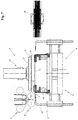
- the coupling means 8 advantageously comprise two or more counter-rotating rollers 38, which define a slit 39 between them for the passage of the two continuous strips 4 of dielectric material with the second electrodes 12 inserted between the internal faces 9 thereof, such slit aligned with the channel 31 defined between the conveyor belts 28, and such rollers are adapted to press the two continuous strips 4 towards each other, in order to firmly retain in position the second electrodes 12 inserted between them.
- the two continuous strips 4 of dielectric material are unwound from the reels 37, transported towards the coupling means 8, support by a plurality of parallel idle rollers 40 that maintain them taut and aligned, and they are driven by the coupling means 8 towards the folding head 6.
- the idle rollers 40 are rotatably supported by the support structure 2.
- the transfer device 27 for the second electrodes 12 is placed upstream of the coupling means 8 in order to feed the second electrodes 12 between the internal faces 9 of the two continuous strips 4 of dielectric material entering into the slit 39 defined between the two counter-rotating rollers 38 of the coupling means 8, as is schematically illustrated in Figures 2 and 3 .
- the outlet mouth for the second electrodes 12 from the channel 31 defined between the guide portions 32 of the two first aspirated conveyor belts 28 is placed in proximity to the inlet mouth at the slit 39 defined between the two counter-rotating rollers 38, such that the second electrodes 12 are transferred by the first conveyor belts 28 to the coupling means 8 substantially without interruption, minimizing the possibility that they undergo undesired movements.
- accompaniment means 36 can be advantageously provided that are adapted to ensure a continuity in the transportation of the second electrodes 12 between the transfer device 27 and the coupling means 8.
- the two continuous strips 4 of dielectric material are unwound from the respective reels 37 and are guided towards the coupling means 8 of the feeding apparatus 3.
- the second electrodes 12 are alternately drawn by a third transport device 30 and by the other from one of the corresponding third storage areas 51, i.e. from one of the corresponding third reels 52, in order to be deposited on the support portion 29 of the corresponding first aspirated conveyor belt 28.
- the second electrodes 12 are then accompanied through the channel 31 by the guide portions 32 of the advantageously aspirated conveyor belts 28 and are guided to be inserted, spaced from each other, between the two continuous strips 4 at the entrance to the coupling means 8.
- the third distribution apparatus 11 feeds the coupling means 8 with a sequence of second electrodes 12 comprising a pre-established number of second electrodes 12, arranged equidistant from each other.
- a delay in the feeding of the subsequent sequence of second electrodes 12 generates a cutting gap 49 in the two continuous strips 4 which however continue to be drawn from the respective reels 37 and directed towards the folding head 6.
- Such cutting gap 49 is substantially constituted by a section of the pair of continuous strips 4, within which the second electrodes 12 are not inserted.
- the coupling means 8 transport the coupled continuous strips 4 with the second electrodes 12 inserted towards the folding head 6.
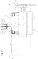
- the stacking surface 7 of the latter is actuated to be lifted with respect to the support columns 18 in order to be brought into an initial position ( Fig. 4 ).
- the folding head 6 is then arranged for a step of cutting the pair 13 of continuous strips 4.
- the head 6 is translated towards the position B and is stopped below the coupling means 8, as illustrated in figure 5 .
- the rear pair of folding blades 19, rear with respect to the advancing direction of the head 6 from the first position A to the second position B, is then brought into the interference position C, in order to retain the pair 13 of continuous strips 4 during the cutting step.
- the stacking surface 7 is actuated to be lifted with respect to the support columns 18 and is brought into a cutting position, illustrated in figure 6 .
- a cutting blade 50 preferably rotating, then cuts the pair 13 of continuous strips 4 at the cutting gap 49, the cutting blade 50 advantageously being in abutment against the edge of the stacking surface.
- the cell 47 formed from the terminated stack of electrodes and separators is then removed by the arm of the robot 48 and a new cell 47 can be formed on the folding head 6.
- the head 6 is brought into the first position A, whereas the front folding blades 19, front with respect to the advancing direction of the folding head 6 itself, are in the interference position C, in order to retain the free end edge of the pair 13 of continuous strips 4.
- the first transport device 22' then deposits a first electrode 10 on the first composite layer 14.
- both pairs of folding blades 19 are slightly lifted and translated along the respective preferred extension directions Y and Y' towards a position of non-interference D, as illustrated in figure 8 , in order to then be newly arranged in the interference position C above the first electrode 10 which was deposited by the first transport device 22', as illustrated in figure 9 .
- the folding blades 19 are actuated to be moved towards the non-interference position D and then towards the new interference position C while the first transport device 22' is depositing the first electrode 10 on the composite layer 14, such that it is the first transport device 22' itself to exert, in this time period, a mechanical action of retention on the stack of electrodes and separators being formed.
- the folding head 6 is then actuated to be moved from the first position A towards the second position B, as illustrated in figure 9 .
- the stacking portion 58 of the head 6 is actuated to be moved from the advanced position S to the receded position R, as illustrated in figure 9 , with the pair of front folding blades 19, front with respect to the advancing direction of the folding head 6, arranged in the interference position C.
- the stacking portion 58 is actuated to be moved towards the receded position R until the pair of front folding blades 19 reaches the emission mouth 59 of the coupling means 8, i.e. it is arranged below the latter.
- the stacking portion 58 is actuated to be newly moved towards the advanced position S and it then remains in the latter position until the trolley 17 has reached the second position B.
- the front folding blades 19, front with respect to the advancing direction of the head 6, assisted by the movement of the stacking portion 58 of the head 6, facilitate the formation of a fold 45 on the pair of continuous strips 4.
- the front locking clam 20, front with respect to the advancing direction of the head 6, is then brought into the engagement position E, advantageously when the folding head 6 has completed about half the distance between the first position A and the second position B, in order to retain in position the second electrode 12 comprised in the composite layer 14 of the pair 13 of continuous strips 4 that the feeding means 3 are releasing on the folding head 6, as illustrated in Figures 10 and 11 .
- the second transport device 22" deposits, on the composite layer 14, a first electrode 10, as illustrated in figure 11 .
- the front locking clamp 20 is brought towards a non-engagement position F and both pairs of folding blades 19 are slightly lifted and translated along the respective preferred extension directions Y and Y' towards a non-interference position D, before then being newly arranged in the interference position C above the first electrode 10 that was deposited by the second transport device 22".
- the locking clamp 20 is actuated to be moved towards the non-engagement position F and the folding blades 19 are actuated to be moved towards the non-interference position D and then towards the new interference position C while the second transport device 22" is depositing the first electrode 10 on the composite layer 14, such that the second transport device 22' exerts a mechanical action of retention on the stack of electrodes and separators being formed, preventing, during the movement of the locking clamp 20 and the folding blades 19, undesired movements of the composite layer 14 and of the second electrode 12 comprised therein, as well as of the first electrode 10.
- the above-described operations are then repeated until a cell 47 is obtained having the desired size, i.e. comprising the desired number of first and second electrodes.
- a machine 1 Illustrated in the enclosed figures is a machine 1 according to the present invention adapted to stack first and second electrodes 10 and 12, both in sheet form. More in detail, illustrated in the enclosed figures is a machine 1 adapted to stack first and second electrodes 10 and 12 both in precut sheet form and drawn from respective storage areas ( Figure 1 ), or adapted to stack first and second electrodes 10 and 12 both in sheet form obtained by means of cutting respective continuous strips of substrate material for electrodes partially coated with an active coating ( Figure 2 ).
- the first and the second electrodes can be separately provided, with the first in precut sheet form and the others obtained via cutting in machines 1 starting from a continuous strip.
- the second electrodes 12 intended to be inserted between the two continuous strips 4 of dielectric material can otherwise be defined on circumscribed areas of a continuous strip of substrate material for electrodes, by means of the deposition of an active coating on such continuous strip only at the aforesaid circumscribed areas.
- the second electrodes 12 would in such case be formed on the continuous strip of substrate material for electrodes by the depositing of the active coating on a plurality of areas spaced from each other, along the preferred extension direction of the continuous strip of substrate material for electrodes.
- the third distribution apparatus 11 of second electrodes 12 of the machine 1 comprises a reel (not illustrated) susceptible to support a winding of the strip of substrate material for electrodes on which a plurality of second electrodes 12 are defined and a device for transferring the strip of second electrodes 12 to the coupling means 8 of the feeding apparatus 3, in order to insert the strip itself between the internal faces 9 of the two continuous strips 4 of dielectric material.
- the machine 1 in accordance with the present invention therefore allows obtaining cells for electric storage batteries with high productive capacity, being adapted to simply and quickly deposit composite layers 14 formed by sections of the pair 13 of continuous strips 4 with an second electrode 12 interposed alternated with first electrodes 10.
- the machine 1 in accordance with the present invention is thus more efficient than the machines of known type, allowing the simultaneous deposition of two separators and one second electrode 12 by translating the folding head 6 from the first position A to the second position B or vice versa,.
- the machine 1 due in particular to the presence of the folding blades 19, and preferably also of the locking clamps 20, of the first and the second transport device 22', 22", as well as of means for drawing the stack formed, such as in particular the arm of a robot 48 as described above, allow exerting a mechanical retention action in a substantially continuous manner on the stack of electrodes and separators during the formation thereof and also at the end of the formation thereof, preventing the latter from being moved and ensuring the maintenance of the optimal alignment initially conferred thereto.
- the machine 1 is adapted to substantially constantly exert a mechanical retention action on the stack of electrodes and separators up to the end of the formation thereof and up to the consequent winding of the formed stack in a double-sided adhesive strip, in order to allow a facilitated movement thereof during the subsequent processing steps.
- the machine 1 according to the present invention is therefore adapted to obtain stacks of electrodes and separators that are optimally aligned with each other, employing any type of separator, without it being required to use, for example, thermo-adhesive separators, and also without requiring the obtainment of fixing points or lines between the continuous strips 4 of dielectric material in order to maintain the electrodes inserted between them in the correct position.
- the electrolytic solution is able to easily penetrate into the interstices between them, also reaching the electrodes interposed therebetween.
- a process for obtaining cells for electric storage batteries also forms the object of the present invention.
- a step is provided for obtaining a pair 13 of continuous strips 4 of dielectric material that are parallel and facing over respective internal faces 9 and provided with two external faces 41 and 42 oriented with opposite directions, with a plurality of second electrodes 12 interposed between the internal faces 9, equidistant along the extension Z of the pair 13 of continuous strips 4.
- the second electrodes 12 are arranged along the extension Z of the pair 13 of continuous strips 4 with the current transport collectors 43" projecting from the pair 13 of continuous strips 4 along a same side, parallel to the preferred extension direction Z of the continuous strips 4.
- the second electrodes 12 are supplied in precut sheet form and the current transport collectors 43" are defined by a tongue projecting from one side of each of the second electrodes 12, as illustrated in figure 1
- each pair of adjacent second electrodes 12, along the extension Z of the pair 13 of continuous strips 4 is arranged with the electrical collectors 43" arranged mirrored, as illustrated in figure 14a .
- the pair 13 of continuous strips 4 of dielectric material with the second electrodes 12 interposed is folded in succession along a plurality of folding lines L orthogonal to the preferred extension direction Z of the two continuous strips 4.
- Each of the folding lines L is in substantially intermediate position between two consecutive second electrodes 12.
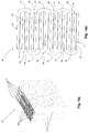
- the succession of folds defines a plurality of support surfaces 44 alternately on the two external faces 41 and 42 of the two continuous strips 4, as is visible in figure 14d , with each of such support surfaces 44 superimposed on one of the second electrodes 12 interposed between the two continuous strips 4.
- the second electrodes 12 are stacked with the current transport collectors 43" aligned, as is visible in figure 14c .
- the process also comprises a step for depositing, in succession, a plurality of first electrodes 10, having opposite polarity with respect to the polarity of the second electrodes 12, each on one of the aforesaid support surfaces 44.
- the first electrodes 10 are deposited on the support surfaces 44 with the current transport collectors 43' projecting all on a same side of the stack. If the first electrodes 10 are supplied in precut sheet form and their current transport collectors 43' are defined by a tongue projecting on one side of each of the each dei first electrodes 12, as illustrated in figure 1 , the first electrodes 10 are advantageously deposited on the support surfaces 44 with the current transport collectors 43' projecting on the same side of the stack on which the current transport collectors 43" of the second electrodes 12 project, aligned spaced from the latter, as illustrated in figure 14c .
- the first electrodes 10 can be deposited on the support surfaces 44 with the current transport collectors 43' projecting on the side of the stack opposite the side on which the current transport collectors 43" of the second electrodes 12 project.
- the folding step and the depositing step are each constituted by a plurality of passages that are alternately executed.
- the folding step comprises a plurality of folding passages, during each of which the pair 13 of continuous strips 4 of dielectric material with the second electrodes 12 interposed is folded along a folding line L, defining a support surface 44 on one of the external faces 41 and 42.
- the depositing step comprises a plurality of depositing passages, during each of which a first electrode 10 is deposited on the support surface 44 defined by the preceding folding passage.
- a depositing passage follows for depositing a first electrode 10 on the support surface 44 defined on one of the two external faces 41 or 42 by the folding passage.
- the step for obtaining a pair 13 of continuous strips 4 of dielectric material that are parallel with a plurality of second electrodes 12 interposed comprises a step for unwinding the two continuous strips 4 of dielectric material from two respective reels 37 and a step for cutting the two continuous strips 4 of dielectric material, advantageously at the end of the formation of the cell 47, constituted by the desired number of stacked first and second electrodes.
- the described process allows obtaining cells for storage batteries in a particularly quick and simple manner, since with only one folding passage, two separators 24 and one second electrode 12 comprised between the two separators 24 are simultaneously deposited on the stack of electrodes and separators being formed.
- Such process is therefore provided with decidedly higher efficiency than the known zigzag stacking processes, which provide for depositing only one separator with each folding passage.
- a cell 47 for electric storage battery which comprises a plurality of first electrodes 10, having a same polarity, and a plurality of second electrodes 12 having a same polarity, opposite the polarity of the first electrodes 10.
- the first electrodes 10 and the second electrodes 12 are alternately stacked on each other and the cell 47 also comprises a plurality of separators 24 interposed between the first and the second electrodes and defined by a plurality of portions of one or more continuous strips 4 of dielectric material.
- the separators 24 are defined by portions of two continuous strips 4 of dielectric material which are coupled, facing over respective internal faces 9 and equipped with two external faces 41 and 42 oriented with opposite directions.
- a plurality of the second electrodes 12 are interposed between the internal faces 9 of the two continuous strips 4, equidistant along the extension of the pair of continuous strips 4.
- the pair of continuous strips 4 is folded into a plurality of folds 45, each obtained along a folding line L orthogonal to the preferred extension direction Z of the two continuous strips 4 of dielectric material and in substantially intermediate position between two of the consecutive second electrodes 12 to form a plurality of superimposed and parallel layers and defining, on the two opposite sides of the cell 47 between the folds 45, a plurality of pockets 46 containing the first electrodes 10.
- the finding thus conceived therefore achieves the preset objects.
Landscapes
- Chemical & Material Sciences (AREA)
- Chemical Kinetics & Catalysis (AREA)
- Electrochemistry (AREA)
- General Chemical & Material Sciences (AREA)
- Engineering & Computer Science (AREA)
- Manufacturing & Machinery (AREA)
- Secondary Cells (AREA)
Claims (15)
- Machine pour l'obtention de cellules pour batteries de stockage électrique, laquelle comprend :- une structure de support (2) reposant sur le sol ;- un appareil d'alimentation (3) d'au moins un ruban continu (4) de matériau diélectrique, monté sur ladite structure de support (2) ;- un premier et un deuxième appareil de distribution (5', 5") d'électrodes montés sur ladite structure de support (2) ;- une tête de pliage (6) montée sur ladite structure de support (2) et munie d'un plan d'empilement (7) susceptible de recevoir ledit au moins un ruban continu (4) de matériau diélectrique depuis ledit appareil d'alimentation (3), laquelle tête de pliage (6) est mobile entre une première position (A) et une deuxième position (B) déplacée par rapport à ladite première position (A) le long d'une direction (X) orthogonale au plan de disposition (n) dudit au moins un ruban continu (4) de matériau diélectrique relâché par ledit appareil d'alimentation (3) pour obtenir une pluralité de feuilles avec lesdites électrodes interposées ;caractérisée en ce que :- ledit appareil d'alimentation (3) est apte à relâcher sur ladite tête de pliage (6) deux ruban continus (4) de matériau diélectrique et comprend des moyens d'accouplement (8) pour accoupler lesdits deux rubans continus (4) dans leur développement avec les respectives faces internes (9) opposées ;- ledit premier appareil de distribution (5') et ledit deuxième appareil de distribution (5") sont aptes à distribuer des premières électrodes (10) ayant la même polarité ;ladite machine (1) comprenant au moins un troisième appareil de distribution (11) de deuxièmes électrodes (12) ayant polarité opposée par rapport à la polarité desdites premières électrodes (10), lequel troisième appareil de distribution (11) est apte à céder lesdites deuxièmes électrodes (12) auxdits moyens d'accouplement (8) dudit appareil d'alimentation (3), entre les faces internes (9) desdits deux rubans continus (4) de matériau diélectrique, espacées les unes des autres, ledit appareil d'alimentation (3) étant apte à relâcher vers ladite tête de pliage (6) ladite paire (13) de rubans continus (4) avec lesdites deuxièmes électrodes (12) interposées et espacées l'une de l'autre le long de la direction préférentielle de développement (Z) desdits deux rubans continus (4),
ladite tête de pliage (6) à chaque passage entre lesdites première position (A) et deuxième position (B) étant apte à recevoir dudit appareil d'alimentation (3) une couche composite (14) formée d'une partie de ladite paire (13) de rubans continus (4) contenant une desdites deuxièmes électrodes (12) et étant susceptible de former un pli (45) entre deux desdites couches composites (14) successives, et ladite tête de pliage (6) étant apte à recevoir sur ladite couche composite (14) une desdites premières électrodes (10) dudit premier appareil de distribution (5') lorsqu'elle se trouve dans ladite première position (A) et une desdites premières électrodes (10) dudit deuxième appareil de distribution (5") lorsqu'elle se trouve sur ladite deuxième position (B) pour former sur ledit plan d'empilement (7) une pile composée desdites couches composites (14) en alternance avec lesdites premières électrodes (10). - Machine selon la revendication 1, caractérisée en ce que ledit au moins troisième appareil de distribution (11) desdites deuxièmes électrodes (12) comprend :- des moyens de fourniture (26) desdites deuxièmes électrodes (12) en succession ; et- un dispositif de transfert (27) desdites deuxièmes électrodes (12), apte à recevoir lesdites deuxièmes électrodes (12) depuis lesdits moyens de fourniture (26) et à les transférer, l'une après l'autre et équidistantes entre elles, auxdits moyens d'accouplement (8) dudit appareil d'alimentation (3), pour les insérer entre les faces internes (9) desdits deux rubans continus (4) de matériau diélectrique.
- Machine selon la revendication 2, caractérisée en ce que lesdits moyens de fourniture (26) sont aptes à céder audit dispositif de transfert (27) lesdites deuxièmes électrodes (12) sous la forme de feuilles et comprennent :- au moins un troisième magasin (51) pour contenir lesdites deuxièmes électrodes (12) sous la forme de feuilles prédécoupées ; et- au moins un troisième dispositif de transport (30), susceptible de prélever lesdites deuxièmes électrodes (12) dudit au moins troisième magasin (51) et de les céder audit dispositif de transfert (27).
- Machine selon la revendication 2, caractérisée en ce que lesdits moyens de fourniture (26) sont aptes à céder audit dispositif de transfert (27) lesdites deuxièmes électrodes (12) sous la forme de feuilles et comprennent :- au moins une troisième bobine (52) susceptible de soutenir un enroulement d'une bande continue (53) de matériau de substrat pour électrodes, sur au moins une partie de laquelle bande continue (53), le long de la direction de développement préférentiel de ladite bande, est déposé un revêtement actif pour la formation desdites deuxièmes électrodes (12) ; et- au moins un troisième dispositif de découpe (54), susceptible de découper ladite bande continue (53) de matériau de substrat pour électrodes partiellement revêtu dudit revêtement actif pour séparer des parties de ladite bande continue (53) chacune apte à définir une desdites deuxièmes électrodes (12) ; et- au moins un troisième dispositif de transport, susceptible de prélever lesdites deuxièmes électrodes (12) séparées de ladite bande continue (53) de matériau de substrat pour électrodes dudit troisième dispositif de découpe (54) et de les relâcher audit dispositif de transfert (27).
- Machine selon la revendication 3 ou 4, caractérisée en ce que ledit au moins un dispositif de transfert (27) comprend deux premiers transporteurs à bande (28) chacun doté d'une partie d'appui (29) apte à recevoir une desdites deuxièmes électrodes (12) sous la forme de feuilles dudit au moins troisième dispositif de transport (30), lesdits deux premiers transporteurs à bande (28) étant disposés côte à côte, définissant entre eux un canal (31) de transfert desdites deuxièmes électrodes (12) aux moyens d'accouplement (8) dudit appareil d'alimentation (3) et étant aptes à guider tous les deux les deuxièmes électrodes (12) posées sur les respectives parties d'appui (29) vers ledit canal (31) pour les transférer auxdits moyens d'accouplement (8).
- Machine selon la revendication 5, caractérisée en ce que ledit canal (31) de transfert desdites deuxièmes électrodes (12) aux moyens d'accouplement (8) dudit appareil d'alimentation (3) est défini entre des respectives parties de guidage (32) desdits deux premiers transporteurs à bande (28), lesquelles se développent essentiellement de façon orthogonale à partir desdites parties d'appui (29).
- Machine selon la revendication 5 ou 6, caractérisée en ce que lesdits deux premiers transporteurs à bande (28) sont aspirés pour maintenir les deuxièmes électrodes (12), en appui sur lesdites parties d'appui (29) et transportées à travers ledit canal (31), dans la position où elles ont été cédées auxdits premiers transporteurs à bande (28) par ledit au moins troisième dispositif de transport (30).
- Machine selon la revendication 1, caractérisée en ce que ledit troisième appareil de distribution (11) de deuxièmes électrodes (12) comprend :- une bobine susceptible de soutenir ladite pluralité de deuxièmes électrodes (12) sous la forme d'un enroulement d'une bande de matériau de substrat pour électrodes, sur une pluralité de zones de cette dernière, localisées et espacées les unes des autres le long de la direction de développement préférentielle de ladite bande, est déposé un revêtement actif qui forme une desdites deuxièmes électrodes (12) ; et- des moyens de transfert de ladite bande sur laquelle sont formées une pluralité desdites deuxièmes électrodes (12) auxdits moyens d'accouplement (8) dudit appareil d'alimentation (3), pour insérer ladite bande entre les faces internes (9) desdits deux rubans continus (4) de matériau diélectrique.
- Machine selon la revendication 2, caractérisée en ce que ledit appareil d'alimentation (3) comprend deux quatrièmes bobines (37) chacune susceptible de soutenir un enroulement d'un respectif ruban (4) de matériau diélectrique, les moyens d'accouplement (8) dudit appareil d'alimentation (3) étant susceptibles de recevoir lesdits rubans (4) de matériau diélectrique desdites quatrièmes bobines (37) et lesdites deuxièmes électrodes (12) du dispositif de transfert (27) dudit troisième appareil de distribution (11) et étant aptes à céder lesdits deux rubans continus (4) accouplés et avec lesdites deuxièmes électrodes (12) interposées à ladite tête de pliage (6).
- Machine selon la revendication 9, caractérisée en ce que lesdits moyens d'accouplement (8) comprennent au moins deux rouleaux tournant en sens opposé (38), lesquels définissent entre eux une fente (39) de passage desdits deux rubans continus (4) de matériau diélectrique avec insérées entre leurs faces internes (9) lesdites deuxièmes électrodes (12) et sont susceptibles de presser lesdits deux rubans continus (4) l'un contre l'autre, pour maintenir solidement en position lesdites deuxièmes électrodes (12) insérées entre eux.
- Machine selon une quelconque des revendications précédentes, caractérisée en ce que ledit premier appareil de distribution (5') et ledit deuxième appareil de distribution (5") comprennent respectivement :- une première bobine (55') et une deuxième bobine (55") susceptibles chacune de soutenir un enroulement respectivement d'une première bande continue (56') et d'une deuxième bande continue (56") de matériau de substrat pour électrodes, sur au moins une partie de chaque bande continue (56' et 56"), le long de la direction de développement préférentielle de ladite bande, est déposé un revêtement actif pour la formation desdites premières électrodes (10) ;- un premier dispositif de découpe (57') et un deuxième dispositif de découpe (57"), susceptibles de découper respectivement ladite première et ladite deuxième bande continue (56' et 56") de matériau de substrat pour électrodes partiellement revêtu dudit revêtement actif pour séparer des parties de ladite première et de ladite deuxième bande continue (56' et 56") chacune apte à définir une desdites premières électrodes (10) ; et- un premier dispositif de transport et un deuxième dispositif de transport, susceptibles de prélever lesdites premières électrodes (10) séparées respectivement de ladite première et de ladite deuxième bande continue (56' et 56") de matériau de substrat pour électrodes et de les relâcher sur ladite tête de pliage (6) lorsque cette dernière se trouve respectivement sur ladite première position (A) et sur ladite deuxième position (B).
- Machine selon la revendication 1, caractérisée en ce que les moyens d'accouplement (8) dudit appareil d'alimentation (3) comprennent une bouche d'émission (59) à travers laquelle ladite paire (13) de rubans continus (4) avec interposées lesdites deuxièmes électrodes (12) est relâchée vers ladite tête de pliage (6) et ladite tête de pliage (6) comprend un chariot (17) qui est mobile le long de ladite direction (X) entre ladite première position (A) et ladite deuxième position (B), et une partie d'empilement (58), comprenant ledit plan d'empilement (7), qui est montée sur ledit chariot (17) mobile le long d'une direction (Z') parallèle à ladite direction préférentielle de développement (Z) desdits deux rubans continus (4) relâchés par ledit appareil d'alimentation (3) entre une position reculée (R), sur laquelle elle est éloignée de la bouche d'émission (59) desdits moyens d'accouplement (8), et une position avancée (S), sur laquelle elle est approchée de la bouche d'émission (59) desdits moyens d'accouplement (8), ladite partie d'empilement (58) étant disposée sur ladite position reculée (R) pour au moins une partie de la course de ladite tête (6) entre ladite première position (A) et ladite deuxième position (B), pour maintenir en tension ladite paire (13) de rubans continus (4) avec interposées lesdites deuxièmes électrodes (12) relâchées par lesdits moyens d'accouplement (8).
- Processus d'obtention de cellules pour batteries de stockage électrique, caractérisé en ce qu'il comprend les phases opérationnelles suivante :- une phase de réalisation d'une paire (13) de rubans continus (4) de matériau diélectrique parallèles, placés en vis à vis sur des faces internes (9) respectives et dotés de deux faces externes (41, 42) orientées selon des sens opposés, avec interposée entre lesdites faces internes (9) desdits deux rubans continus (4) équidistants le long du développement de ladite paire de rubans continus (4), une pluralité de deuxièmes électrodes (12) ;- une phase de pliage, pendant laquelle ladite paire (13) de rubans continus (4) de matériau diélectrique avec interposées lesdites deuxièmes électrodes (12) est pliée en succession le long d'une pluralité de lignes de pliage (L) orthogonales à la direction de développement préférentielle (Z) desdits deux rubans continus (4), chacune desdites lignes de pliage (L) étant en position essentiellement intermédiaire entre deux desdites deuxièmes électrodes (12) consécutives, ladite succession de pliages définissant une pluralité de plans d'appui (44) en alternance sur les deux faces externes (41, 24) desdits deux rubans continus (4), chacun desdits plans d'appui (44) étant superposé à une desdites deuxièmes électrodes (12) interposées entre lesdits deux rubans continus (4) ;- une phase de dépôt en succession d'une pluralité de premières électrodes (10) ayant polarité opposée par rapport à la polarité desdites deuxièmes électrodes (12), chacune sur un desdits plans d'appui (44).
- Processus d'obtention de batteries de stockage électrique selon la revendication 13, caractérisé en ce que ladite phase d'obtention d'une paire (13) de rubans continus (4) de matériau diélectrique parallèles avec interposée une pluralité desdites deuxièmes électrodes (12) comprend une phase de déroulement desdits deux rubans continus (4) de matériau diélectrique à partir de deux bobines (37) respectives et une phase de découpe desdits deux rubans continus (4) de matériau diélectrique.
- Cellule pour batterie de stockage électrique qui comprend :- une pluralité de premières électrodes (10) ayant la même polarité ;- une pluralité de deuxièmes électrodes (12) ayant une même polarité, opposée à la polarité desdites premières électrodes (10), lesdites premières électrodes (10) et lesdites deuxièmes électrodes (12) étant empilées l'une sur l'autre en alternance ;- une pluralité de séparateurs (24) interposés entre lesdites premières et deuxièmes électrodes et définis par une pluralité de parties d'au moins un ruban continu (4) de matériau diélectrique ;caractérisée en ce que lesdits séparateurs (24) sont définis par des parties de deux rubans continus (4) de matériau diélectrique lesquels sont accouplés, placés en vis à vis sur des faces internes (9) respectives et dotés de deux faces externes (41, 42) orientées selon des sens opposés, avec interposée entre lesdites faces internes (9) essentiellement équidistante le long du développement de ladite paire de rubans continus (4) une pluralité desdites deuxièmes électrodes (12) ; ladite paire (13) de rubans continus (4) étant repliée en une pluralité de plis (45) chacun le long d'une ligne de pliage (L) orthogonale à la direction de développement préférentielle desdits deux rubans continus (4) de matériau diélectrique et en position essentiellement intermédiaire entre deux desdites deuxièmes électrodes (12) consécutives pour former une pluralité de feuilles superposées et parallèles et définissant sur les deux côtés opposées entre lesdits plis (45) une pluralité de poches (46) contenant lesdites premières électrodes (10).
Applications Claiming Priority (2)
| Application Number | Priority Date | Filing Date | Title |
|---|---|---|---|
| IT000167A ITPD20120167A1 (it) | 2012-05-24 | 2012-05-24 | Macchina e procedimento per la realizzazione di celle per accumulatori elettrici e cella per accumulatore elettrico |
| PCT/IB2013/001025 WO2013175296A1 (fr) | 2012-05-24 | 2013-05-23 | Machine et processus d'obtention de cellules pour batteries de stockage électrique et cellule pour batterie de stockage électrique |
Publications (2)
| Publication Number | Publication Date |
|---|---|
| EP2856552A1 EP2856552A1 (fr) | 2015-04-08 |
| EP2856552B1 true EP2856552B1 (fr) | 2016-05-25 |
Family
ID=46584112
Family Applications (1)
| Application Number | Title | Priority Date | Filing Date |
|---|---|---|---|
| EP13727972.5A Active EP2856552B1 (fr) | 2012-05-24 | 2013-05-23 | Machine et processus d'obtention de cellules pour batteries de stockage électrique et cellule pour batterie de stockage électrique |
Country Status (6)
| Country | Link |
|---|---|
| US (1) | US9991547B2 (fr) |
| EP (1) | EP2856552B1 (fr) |
| KR (1) | KR102091896B1 (fr) |
| CN (1) | CN104471776B (fr) |
| IT (1) | ITPD20120167A1 (fr) |
| WO (1) | WO2013175296A1 (fr) |
Cited By (4)
| Publication number | Priority date | Publication date | Assignee | Title |
|---|---|---|---|---|
| EP3573165A1 (fr) * | 2016-04-01 | 2019-11-27 | NS Co., Ltd. | Procédé de fabrication d'un ensemble d'électrodes |
| WO2023282722A1 (fr) * | 2021-07-09 | 2023-01-12 | Lg Energy Solution, Ltd. | Équipement de fabrication d'ensemble et procédé d'assemblage d'électrode |
| WO2023073744A1 (fr) * | 2021-10-29 | 2023-05-04 | P.I.T. S.R.L. | Machine de fabrication de dispositifs d'accumulation d'énergie électrique |
| US12218380B2 (en) | 2021-07-09 | 2025-02-04 | Lg Energy Solution, Ltd. | Manufacturing method for electrode assembly and electrode assembly manufacturing equipment |
Families Citing this family (37)
| Publication number | Priority date | Publication date | Assignee | Title |
|---|---|---|---|---|
| CN103682460A (zh) * | 2013-12-19 | 2014-03-26 | 深圳市吉阳自动化科技有限公司 | 叠片机及其叠片方法 |
| KR102700153B1 (ko) | 2016-05-02 | 2024-08-27 | 삼성에스디아이 주식회사 | 전극 조립체 |
| US20190237272A1 (en) * | 2016-06-20 | 2019-08-01 | Kabushiki Kaisha Toyota Jidoshokki | Electrode stacking device |
| WO2018004185A1 (fr) * | 2016-06-27 | 2018-01-04 | 삼성에스디아이(주) | Dispositif d'empilage pour batterie secondaire, procédé d'empilage l'utilisant et batterie secondaire ainsi obtenue |
| KR20180001458A (ko) * | 2016-06-27 | 2018-01-04 | 삼성에스디아이 주식회사 | 이차 전지용 스택 장치, 이를 이용한 스택 방법 및 이에 따른 이차 전지 |
| KR102071868B1 (ko) | 2016-08-26 | 2020-01-31 | 주식회사 엘지화학 | 에어 블로잉 유닛을 포함하는 전극조립체 제조 장치 |
| IT201600119013A1 (it) * | 2016-11-24 | 2018-05-24 | Manz Italy Srl | Produzione di Dispositivi di Accumulo di Energia Elettrica |
| JP6635204B2 (ja) * | 2016-12-21 | 2020-01-22 | 株式会社村田製作所 | 電極積層体の製造装置 |
| DE102018200958A1 (de) | 2018-01-22 | 2019-07-25 | Volkswagen Aktiengesellschaft | Verfahren zum Herstellen eines Elektrodenstapels für Energiespeicher, Stapelanlage |
| KR101981010B1 (ko) * | 2018-08-01 | 2019-08-28 | 정연길 | 이차 전지 제조 설비 및 이를 사용한 이차 전지 제조 방법 |
| CN108891987A (zh) * | 2018-08-28 | 2018-11-27 | 四川伊索新型节能材料有限公司 | 一种纤维编织件压板机 |
| KR101959082B1 (ko) * | 2018-09-07 | 2019-03-18 | 조기봉 | 이차전지의 셀 스택 고속 제조장치 |
| JP6879282B2 (ja) * | 2018-11-06 | 2021-06-02 | トヨタ自動車株式会社 | シート状電極の積層体製造装置 |
| CN113196537B (zh) * | 2018-12-19 | 2024-03-22 | Lg电子株式会社 | 二次电池的电池堆制造装置 |
| CN110994039B (zh) * | 2019-12-25 | 2025-04-25 | 东莞市超业精密设备有限公司 | 一种复合叠片生产线及复合叠片方法 |
| CN113745667B (zh) * | 2020-05-28 | 2023-10-13 | 沃尔沃汽车公司 | 装配方形锂离子电池的电极的系统和方法 |
| JP7488141B2 (ja) * | 2020-07-14 | 2024-05-21 | 株式会社京都製作所 | 積層セルの製造装置 |
| CN112117495B (zh) * | 2020-10-20 | 2025-02-18 | 深圳吉阳智能科技有限公司 | 叠片设备、方法及叠片结构 |
| EP4075561B1 (fr) * | 2020-12-18 | 2023-12-13 | Contemporary Amperex Technology Co., Limited | Assemblage d'électrodes et méthode de fabrication et système de fabrication associé, cellule de batterie, batterie et appareil électrique |
| IT202100009146A1 (it) | 2021-04-12 | 2022-10-12 | Ms2 S R L | Macchina per la realizzazione di batterie elettriche |
| CN215299325U (zh) * | 2021-05-25 | 2021-12-24 | 深圳吉阳智能科技有限公司 | 叠片机构 |
| IT202100014459A1 (it) * | 2021-06-03 | 2022-12-03 | Manz Italy Srl | Apparato di taglio e convogliamento di un nastro di materiale e relativo metodo per la produzione di dispositivi di accumulo di energia elettrica |
| IT202100030254A1 (it) | 2021-11-30 | 2023-05-30 | P I T S R L | Apparecchiatura per la formazione di un nastro di elettrodi per dispositivi di accumulo di energia elettrica |
| IT202100030281A1 (it) | 2021-11-30 | 2023-05-30 | P I T S R L | Apparecchiatura per la formazione di un nastro di elettrodi per dispositivi di accumulo di energia elettrica |
| IT202100030239A1 (it) | 2021-11-30 | 2023-05-30 | P I T S R L | Macchina per la realizzazione di dispositivi di accumulo di energia elettrica |
| JP7369231B2 (ja) * | 2022-03-31 | 2023-10-25 | Nissha株式会社 | 積層型電池の製造方法、積層型電池の製造装置及び積層型電池 |
| CN114803443B (zh) * | 2022-05-24 | 2024-07-23 | 惠州市华维机电设备有限公司 | 一种电芯生产线用物料传送方法 |
| DE102022115207A1 (de) * | 2022-06-17 | 2023-12-28 | Mb Atech Gmbh | Vorrichtung zur Herstellung von Modulen oder Vorstufen von Modulen |
| IT202200020736A1 (it) * | 2022-10-07 | 2024-04-07 | Gd Spa | Apparato di impilamento per impilare alternati tra loro un separatore nastriforme continuo e lamine in foglio e metodo per impilare un separatore nastriforme continuo e lamine in foglio |
| IT202200020709A1 (it) * | 2022-10-07 | 2024-04-07 | Gd Spa | Apparato di impilamento per impilare alternati tra loro un separatore nastriforme continuo e lamine in foglio e metodo per impilare un separatore nastriforme continuo e lamine in foglio |
| IT202200020733A1 (it) * | 2022-10-07 | 2024-04-07 | Gd Spa | Apparato di impilamento per impilare un separatore continuo e lamine in foglio |
| IT202200020712A1 (it) * | 2022-10-07 | 2024-04-07 | Gd Spa | Apparato di impilamento per impilare alternati tra loro un separatore nastriforme continuo e lamine in foglio e metodo per impilare un separatore nastriforme continuo e lamine in foglio |
| CN115548452B (zh) * | 2022-10-08 | 2026-01-06 | 无锡先导智能装备股份有限公司 | 叠片装置 |
| CN116387636B (zh) * | 2023-03-20 | 2023-12-12 | 东莞市冠逸自动化科技有限公司 | 一种模叠一体机 |
| WO2025257870A1 (fr) | 2024-06-13 | 2025-12-18 | P.I.T. S.R.L. | Appareil d'enroulement d'un empilement d'électrodes dans une machine de fabrication de dispositifs de stockage d'énergie électrique |
| WO2025257869A1 (fr) | 2024-06-13 | 2025-12-18 | P.I.T. S.R.L. | Appareil pour former un empilement d'électrodes destiné à être utilisé dans la fabrication de dispositifs de stockage d'énergie électrique |
| KR102915487B1 (ko) * | 2025-06-18 | 2026-01-20 | 주식회사 비이아이 | 전극조립체의 제조시스템 및 제조방법 |
Family Cites Families (8)
| Publication number | Priority date | Publication date | Assignee | Title |
|---|---|---|---|---|
| US5563007A (en) * | 1995-01-11 | 1996-10-08 | Entek Manufacturing Inc. | Method of enveloping and assembling battery plates and product produced thereby |
| KR100336395B1 (ko) | 2000-06-12 | 2002-05-10 | 홍지준 | 리튬 이차 전지의 제조방법 |
| WO2006014989A2 (fr) * | 2004-07-28 | 2006-02-09 | Edward Samuels | Machine d'intercalation et procede d'empilement d'objets plats |
| CN2842758Y (zh) * | 2005-09-09 | 2006-11-29 | 东莞新能源电子科技有限公司 | 锂离子电池之电池芯的叠片结构 |
| CN101355180A (zh) | 2008-09-09 | 2009-01-28 | 吉安市优特利科技有限公司 | 一种锂离子动力电池的电芯构造 |
| KR101255351B1 (ko) * | 2009-04-28 | 2013-04-16 | 에스케이이노베이션 주식회사 | 2차 전지 내부 셀 스택 적층 장치 및 방법 |
| CN102986078B (zh) | 2010-05-14 | 2015-11-25 | 曼兹意大利有限责任公司 | 用于电能存储装置的生产的设备和方法 |
| CN103081200B (zh) * | 2010-08-11 | 2015-08-19 | 日本自动精机株式会社 | 正负极板的层积方法及其装置 |
-
2012
- 2012-05-24 IT IT000167A patent/ITPD20120167A1/it unknown
-
2013
- 2013-05-23 KR KR1020147036070A patent/KR102091896B1/ko active Active
- 2013-05-23 WO PCT/IB2013/001025 patent/WO2013175296A1/fr not_active Ceased
- 2013-05-23 US US14/403,195 patent/US9991547B2/en active Active
- 2013-05-23 CN CN201380027185.9A patent/CN104471776B/zh active Active
- 2013-05-23 EP EP13727972.5A patent/EP2856552B1/fr active Active
Cited By (14)
| Publication number | Priority date | Publication date | Assignee | Title |
|---|---|---|---|---|
| EP3573165A1 (fr) * | 2016-04-01 | 2019-11-27 | NS Co., Ltd. | Procédé de fabrication d'un ensemble d'électrodes |
| EP3573164A1 (fr) * | 2016-04-01 | 2019-11-27 | NS Co., Ltd. | Appareil et procédé de fabrication d'un ensemble d'électrode et ensemble d'électrode ainsi fabriqué |
| EP3573166B1 (fr) * | 2016-04-01 | 2022-02-09 | NS Co., Ltd. | Ensemble d'électrodes |
| US12244037B2 (en) | 2021-07-09 | 2025-03-04 | Lg Energy Solution, Ltd. | Manufacturing method for electrode assembly |
| US12218380B2 (en) | 2021-07-09 | 2025-02-04 | Lg Energy Solution, Ltd. | Manufacturing method for electrode assembly and electrode assembly manufacturing equipment |
| WO2023282722A1 (fr) * | 2021-07-09 | 2023-01-12 | Lg Energy Solution, Ltd. | Équipement de fabrication d'ensemble et procédé d'assemblage d'électrode |
| US12244038B2 (en) | 2021-07-09 | 2025-03-04 | Lg Energy Solution, Ltd. | Electrode assembly |
| US12272839B2 (en) | 2021-07-09 | 2025-04-08 | Lg Energy Solution, Ltd. | Electrode assembly |
| US12355105B2 (en) | 2021-07-09 | 2025-07-08 | Lg Energy Solution, Ltd. | Electrode assembly |
| US12362431B2 (en) | 2021-07-09 | 2025-07-15 | Lg Energy Solution, Ltd. | Electrode assembly |
| US12374757B2 (en) | 2021-07-09 | 2025-07-29 | Lg Energy Solution, Ltd. | Electrode assembly |
| US12388156B2 (en) | 2021-07-09 | 2025-08-12 | Lg Energy Solution, Ltd. | Assembly manufacturing equipment and method for electrode assembly |
| US12401093B2 (en) | 2021-07-09 | 2025-08-26 | Lg Energy Solution, Ltd. | Assembly manufacturing equipment and method for electrode assembly |
| WO2023073744A1 (fr) * | 2021-10-29 | 2023-05-04 | P.I.T. S.R.L. | Machine de fabrication de dispositifs d'accumulation d'énergie électrique |
Also Published As
| Publication number | Publication date |
|---|---|
| US9991547B2 (en) | 2018-06-05 |
| CN104471776A (zh) | 2015-03-25 |
| WO2013175296A1 (fr) | 2013-11-28 |
| EP2856552A1 (fr) | 2015-04-08 |
| CN104471776B (zh) | 2017-05-10 |
| ITPD20120167A1 (it) | 2013-11-25 |
| KR102091896B1 (ko) | 2020-05-28 |
| KR20150021069A (ko) | 2015-02-27 |
| US20150162638A1 (en) | 2015-06-11 |
Similar Documents
| Publication | Publication Date | Title |
|---|---|---|
| EP2856552B1 (fr) | Machine et processus d'obtention de cellules pour batteries de stockage électrique et cellule pour batterie de stockage électrique | |
| US8882858B2 (en) | Apparatus and method for the production of electric energy storage devices | |
| CN104241700B (zh) | 叠片电芯制备装置 | |
| KR102110630B1 (ko) | 전극 스택을 제작하기 위한 장치 및 방법 | |
| CN102969538A (zh) | 锂离子动力电池的电芯叠片机 | |
| DE102017216213A1 (de) | Verfahren zur Herstellung eines Elektrodenstapels | |
| JP2014165055A (ja) | 積層型電池製造方法及びその装置 | |
| CN103247826B (zh) | 卷绕装置 | |
| WO2012144008A1 (fr) | Procédé et dispositif de fabrication d'accumulateur | |
| CN104124477B (zh) | 铅酸电池叠片装置及铅酸电池叠片方法 | |
| KR102634753B1 (ko) | 이차전지 셀 스택 장치의 분리막 보정유닛 | |
| CN217371331U (zh) | 一种电池串焊接设备 | |
| CN219350289U (zh) | 高速切叠一体机 | |
| CN109599585A (zh) | 一种电芯绝缘贴片设备 | |
| CN217848053U (zh) | 隔膜双放卷电芯循环式多工位多片叠切一体设备 | |
| KR20040079537A (ko) | 와인딩 타입의 셀 스태킹머신용 와인딩 장치 | |
| TWM442248U (en) | Multi-slot material cutting and feeding device for tape-like articles | |
| CN205790229U (zh) | 一种叠片电池单元制作装置 | |
| CN210575883U (zh) | 焊带供料装置及电池片串焊设备 | |
| KR20040079533A (ko) | 와인딩 타입의 셀 스태킹머신 | |
| EP3849010A1 (fr) | Machine d'enveloppement pour envelopper des plaques de batteries de stockage électrique et procédé de manipulation de plaques pour batteries de stockage électrique dans ladite machine d'enveloppement | |
| EP4152456B1 (fr) | Ensemble d'électrodes destiné à être utilisé dans une batterie, appareil de fabrication de celui-ci et son procédé de fabrication | |
| EP4659934A1 (fr) | Procédé de fabrication de batterie secondaire et appareil de fabrication de batterie secondaire | |
| KR20040079538A (ko) | 와인딩 타입의 셀 스태킹머신용 셀로더 | |
| KR20260023917A (ko) | 전극조립체 제조장치 |
Legal Events
| Date | Code | Title | Description |
|---|---|---|---|
| PUAI | Public reference made under article 153(3) epc to a published international application that has entered the european phase |
Free format text: ORIGINAL CODE: 0009012 |
|
| 17P | Request for examination filed |
Effective date: 20141121 |
|
| AK | Designated contracting states |
Kind code of ref document: A1 Designated state(s): AL AT BE BG CH CY CZ DE DK EE ES FI FR GB GR HR HU IE IS IT LI LT LU LV MC MK MT NL NO PL PT RO RS SE SI SK SM TR |
|
| AX | Request for extension of the european patent |
Extension state: BA ME |
|
| DAX | Request for extension of the european patent (deleted) | ||
| RIC1 | Information provided on ipc code assigned before grant |
Ipc: H01M 2/18 20060101ALN20150930BHEP Ipc: H01M 10/0583 20100101ALN20150930BHEP Ipc: H01M 10/04 20060101AFI20150930BHEP Ipc: B65H 45/00 20060101ALI20150930BHEP |
|
| RIC1 | Information provided on ipc code assigned before grant |
Ipc: H01M 2/18 20060101ALN20151015BHEP Ipc: H01M 10/0583 20100101ALN20151015BHEP Ipc: H01M 10/04 20060101AFI20151015BHEP Ipc: B65H 45/00 20060101ALI20151015BHEP |
|
| GRAP | Despatch of communication of intention to grant a patent |
Free format text: ORIGINAL CODE: EPIDOSNIGR1 |
|
| RIC1 | Information provided on ipc code assigned before grant |
Ipc: B65H 45/00 20060101ALI20151124BHEP Ipc: H01M 2/18 20060101ALN20151124BHEP Ipc: H01M 10/04 20060101AFI20151124BHEP Ipc: H01M 10/0583 20100101ALN20151124BHEP |
|
| INTG | Intention to grant announced |
Effective date: 20151214 |
|
| GRAS | Grant fee paid |
Free format text: ORIGINAL CODE: EPIDOSNIGR3 |
|
| GRAA | (expected) grant |
Free format text: ORIGINAL CODE: 0009210 |
|
| AK | Designated contracting states |
Kind code of ref document: B1 Designated state(s): AL AT BE BG CH CY CZ DE DK EE ES FI FR GB GR HR HU IE IS IT LI LT LU LV MC MK MT NL NO PL PT RO RS SE SI SK SM TR |
|
| REG | Reference to a national code |
Ref country code: GB Ref legal event code: FG4D |
|
| REG | Reference to a national code |
Ref country code: CH Ref legal event code: EP |
|
| REG | Reference to a national code |
Ref country code: IE Ref legal event code: FG4D Ref country code: AT Ref legal event code: REF Ref document number: 802998 Country of ref document: AT Kind code of ref document: T Effective date: 20160615 |
|
| REG | Reference to a national code |
Ref country code: DE Ref legal event code: R096 Ref document number: 602013007998 Country of ref document: DE |
|
| REG | Reference to a national code |
Ref country code: LT Ref legal event code: MG4D |
|
| REG | Reference to a national code |
Ref country code: NL Ref legal event code: MP Effective date: 20160525 |
|
| PG25 | Lapsed in a contracting state [announced via postgrant information from national office to epo] |
Ref country code: LT Free format text: LAPSE BECAUSE OF FAILURE TO SUBMIT A TRANSLATION OF THE DESCRIPTION OR TO PAY THE FEE WITHIN THE PRESCRIBED TIME-LIMIT Effective date: 20160525 Ref country code: FI Free format text: LAPSE BECAUSE OF FAILURE TO SUBMIT A TRANSLATION OF THE DESCRIPTION OR TO PAY THE FEE WITHIN THE PRESCRIBED TIME-LIMIT Effective date: 20160525 Ref country code: NL Free format text: LAPSE BECAUSE OF FAILURE TO SUBMIT A TRANSLATION OF THE DESCRIPTION OR TO PAY THE FEE WITHIN THE PRESCRIBED TIME-LIMIT Effective date: 20160525 Ref country code: NO Free format text: LAPSE BECAUSE OF FAILURE TO SUBMIT A TRANSLATION OF THE DESCRIPTION OR TO PAY THE FEE WITHIN THE PRESCRIBED TIME-LIMIT Effective date: 20160825 |
|
| REG | Reference to a national code |
Ref country code: AT Ref legal event code: MK05 Ref document number: 802998 Country of ref document: AT Kind code of ref document: T Effective date: 20160525 |
|
| PG25 | Lapsed in a contracting state [announced via postgrant information from national office to epo] |
Ref country code: RS Free format text: LAPSE BECAUSE OF FAILURE TO SUBMIT A TRANSLATION OF THE DESCRIPTION OR TO PAY THE FEE WITHIN THE PRESCRIBED TIME-LIMIT Effective date: 20160525 Ref country code: PT Free format text: LAPSE BECAUSE OF FAILURE TO SUBMIT A TRANSLATION OF THE DESCRIPTION OR TO PAY THE FEE WITHIN THE PRESCRIBED TIME-LIMIT Effective date: 20160926 Ref country code: SE Free format text: LAPSE BECAUSE OF FAILURE TO SUBMIT A TRANSLATION OF THE DESCRIPTION OR TO PAY THE FEE WITHIN THE PRESCRIBED TIME-LIMIT Effective date: 20160525 Ref country code: GR Free format text: LAPSE BECAUSE OF FAILURE TO SUBMIT A TRANSLATION OF THE DESCRIPTION OR TO PAY THE FEE WITHIN THE PRESCRIBED TIME-LIMIT Effective date: 20160826 Ref country code: LV Free format text: LAPSE BECAUSE OF FAILURE TO SUBMIT A TRANSLATION OF THE DESCRIPTION OR TO PAY THE FEE WITHIN THE PRESCRIBED TIME-LIMIT Effective date: 20160525 Ref country code: ES Free format text: LAPSE BECAUSE OF FAILURE TO SUBMIT A TRANSLATION OF THE DESCRIPTION OR TO PAY THE FEE WITHIN THE PRESCRIBED TIME-LIMIT Effective date: 20160525 |
|
| PG25 | Lapsed in a contracting state [announced via postgrant information from national office to epo] |
Ref country code: SK Free format text: LAPSE BECAUSE OF FAILURE TO SUBMIT A TRANSLATION OF THE DESCRIPTION OR TO PAY THE FEE WITHIN THE PRESCRIBED TIME-LIMIT Effective date: 20160525 Ref country code: EE Free format text: LAPSE BECAUSE OF FAILURE TO SUBMIT A TRANSLATION OF THE DESCRIPTION OR TO PAY THE FEE WITHIN THE PRESCRIBED TIME-LIMIT Effective date: 20160525 Ref country code: RO Free format text: LAPSE BECAUSE OF FAILURE TO SUBMIT A TRANSLATION OF THE DESCRIPTION OR TO PAY THE FEE WITHIN THE PRESCRIBED TIME-LIMIT Effective date: 20160525 Ref country code: CZ Free format text: LAPSE BECAUSE OF FAILURE TO SUBMIT A TRANSLATION OF THE DESCRIPTION OR TO PAY THE FEE WITHIN THE PRESCRIBED TIME-LIMIT Effective date: 20160525 Ref country code: DK Free format text: LAPSE BECAUSE OF FAILURE TO SUBMIT A TRANSLATION OF THE DESCRIPTION OR TO PAY THE FEE WITHIN THE PRESCRIBED TIME-LIMIT Effective date: 20160525 |
|
| PG25 | Lapsed in a contracting state [announced via postgrant information from national office to epo] |
Ref country code: SM Free format text: LAPSE BECAUSE OF FAILURE TO SUBMIT A TRANSLATION OF THE DESCRIPTION OR TO PAY THE FEE WITHIN THE PRESCRIBED TIME-LIMIT Effective date: 20160525 Ref country code: AT Free format text: LAPSE BECAUSE OF FAILURE TO SUBMIT A TRANSLATION OF THE DESCRIPTION OR TO PAY THE FEE WITHIN THE PRESCRIBED TIME-LIMIT Effective date: 20160525 Ref country code: PL Free format text: LAPSE BECAUSE OF FAILURE TO SUBMIT A TRANSLATION OF THE DESCRIPTION OR TO PAY THE FEE WITHIN THE PRESCRIBED TIME-LIMIT Effective date: 20160525 Ref country code: BE Free format text: LAPSE BECAUSE OF FAILURE TO SUBMIT A TRANSLATION OF THE DESCRIPTION OR TO PAY THE FEE WITHIN THE PRESCRIBED TIME-LIMIT Effective date: 20160525 |
|
| REG | Reference to a national code |
Ref country code: DE Ref legal event code: R097 Ref document number: 602013007998 Country of ref document: DE |
|
| PLBE | No opposition filed within time limit |
Free format text: ORIGINAL CODE: 0009261 |
|
| STAA | Information on the status of an ep patent application or granted ep patent |
Free format text: STATUS: NO OPPOSITION FILED WITHIN TIME LIMIT |
|
| 26N | No opposition filed |
Effective date: 20170228 |
|
| REG | Reference to a national code |
Ref country code: FR Ref legal event code: PLFP Year of fee payment: 5 |
|
| PG25 | Lapsed in a contracting state [announced via postgrant information from national office to epo] |
Ref country code: SI Free format text: LAPSE BECAUSE OF FAILURE TO SUBMIT A TRANSLATION OF THE DESCRIPTION OR TO PAY THE FEE WITHIN THE PRESCRIBED TIME-LIMIT Effective date: 20160525 |
|
| PG25 | Lapsed in a contracting state [announced via postgrant information from national office to epo] |
Ref country code: LU Free format text: LAPSE BECAUSE OF NON-PAYMENT OF DUE FEES Effective date: 20170531 |
|
| REG | Reference to a national code |
Ref country code: CH Ref legal event code: PL |
|
| PG25 | Lapsed in a contracting state [announced via postgrant information from national office to epo] |
Ref country code: MC Free format text: LAPSE BECAUSE OF FAILURE TO SUBMIT A TRANSLATION OF THE DESCRIPTION OR TO PAY THE FEE WITHIN THE PRESCRIBED TIME-LIMIT Effective date: 20160525 |
|
| REG | Reference to a national code |
Ref country code: IE Ref legal event code: MM4A |
|
| PG25 | Lapsed in a contracting state [announced via postgrant information from national office to epo] |
Ref country code: CH Free format text: LAPSE BECAUSE OF NON-PAYMENT OF DUE FEES Effective date: 20170531 Ref country code: LI Free format text: LAPSE BECAUSE OF NON-PAYMENT OF DUE FEES Effective date: 20170531 |
|
| PG25 | Lapsed in a contracting state [announced via postgrant information from national office to epo] |
Ref country code: LU Free format text: LAPSE BECAUSE OF NON-PAYMENT OF DUE FEES Effective date: 20170523 |
|
| PG25 | Lapsed in a contracting state [announced via postgrant information from national office to epo] |
Ref country code: IE Free format text: LAPSE BECAUSE OF NON-PAYMENT OF DUE FEES Effective date: 20170523 |
|
| REG | Reference to a national code |
Ref country code: FR Ref legal event code: PLFP Year of fee payment: 6 |
|
| PG25 | Lapsed in a contracting state [announced via postgrant information from national office to epo] |
Ref country code: MT Free format text: LAPSE BECAUSE OF NON-PAYMENT OF DUE FEES Effective date: 20170523 |
|
| PG25 | Lapsed in a contracting state [announced via postgrant information from national office to epo] |
Ref country code: AL Free format text: LAPSE BECAUSE OF FAILURE TO SUBMIT A TRANSLATION OF THE DESCRIPTION OR TO PAY THE FEE WITHIN THE PRESCRIBED TIME-LIMIT Effective date: 20160525 |
|
| PG25 | Lapsed in a contracting state [announced via postgrant information from national office to epo] |
Ref country code: HU Free format text: LAPSE BECAUSE OF FAILURE TO SUBMIT A TRANSLATION OF THE DESCRIPTION OR TO PAY THE FEE WITHIN THE PRESCRIBED TIME-LIMIT; INVALID AB INITIO Effective date: 20130523 |
|
| PG25 | Lapsed in a contracting state [announced via postgrant information from national office to epo] |
Ref country code: BG Free format text: LAPSE BECAUSE OF FAILURE TO SUBMIT A TRANSLATION OF THE DESCRIPTION OR TO PAY THE FEE WITHIN THE PRESCRIBED TIME-LIMIT Effective date: 20160525 |
|
| PG25 | Lapsed in a contracting state [announced via postgrant information from national office to epo] |
Ref country code: CY Free format text: LAPSE BECAUSE OF FAILURE TO SUBMIT A TRANSLATION OF THE DESCRIPTION OR TO PAY THE FEE WITHIN THE PRESCRIBED TIME-LIMIT Effective date: 20160525 |
|
| PG25 | Lapsed in a contracting state [announced via postgrant information from national office to epo] |
Ref country code: MK Free format text: LAPSE BECAUSE OF FAILURE TO SUBMIT A TRANSLATION OF THE DESCRIPTION OR TO PAY THE FEE WITHIN THE PRESCRIBED TIME-LIMIT Effective date: 20160525 |
|
| PG25 | Lapsed in a contracting state [announced via postgrant information from national office to epo] |
Ref country code: TR Free format text: LAPSE BECAUSE OF FAILURE TO SUBMIT A TRANSLATION OF THE DESCRIPTION OR TO PAY THE FEE WITHIN THE PRESCRIBED TIME-LIMIT Effective date: 20160525 |
|
| PG25 | Lapsed in a contracting state [announced via postgrant information from national office to epo] |
Ref country code: HR Free format text: LAPSE BECAUSE OF FAILURE TO SUBMIT A TRANSLATION OF THE DESCRIPTION OR TO PAY THE FEE WITHIN THE PRESCRIBED TIME-LIMIT Effective date: 20160525 |
|
| PG25 | Lapsed in a contracting state [announced via postgrant information from national office to epo] |
Ref country code: IS Free format text: LAPSE BECAUSE OF FAILURE TO SUBMIT A TRANSLATION OF THE DESCRIPTION OR TO PAY THE FEE WITHIN THE PRESCRIBED TIME-LIMIT Effective date: 20160925 |
|
| P01 | Opt-out of the competence of the unified patent court (upc) registered |
Effective date: 20230306 |
|
| PGFP | Annual fee paid to national office [announced via postgrant information from national office to epo] |
Ref country code: DE Payment date: 20250521 Year of fee payment: 13 |
|
| PGFP | Annual fee paid to national office [announced via postgrant information from national office to epo] |
Ref country code: GB Payment date: 20250521 Year of fee payment: 13 |
|
| PGFP | Annual fee paid to national office [announced via postgrant information from national office to epo] |
Ref country code: IT Payment date: 20250528 Year of fee payment: 13 |
|
| PGFP | Annual fee paid to national office [announced via postgrant information from national office to epo] |
Ref country code: FR Payment date: 20250528 Year of fee payment: 13 |