EP2856058B1 - Echangeur de chaleur a collecteur renforce - Google Patents
Echangeur de chaleur a collecteur renforce Download PDFInfo
- Publication number
- EP2856058B1 EP2856058B1 EP13724231.9A EP13724231A EP2856058B1 EP 2856058 B1 EP2856058 B1 EP 2856058B1 EP 13724231 A EP13724231 A EP 13724231A EP 2856058 B1 EP2856058 B1 EP 2856058B1
- Authority
- EP
- European Patent Office
- Prior art keywords
- wall
- exchanger according
- heat exchange
- tube
- exchange body
- Prior art date
- Legal status (The legal status is an assumption and is not a legal conclusion. Google has not performed a legal analysis and makes no representation as to the accuracy of the status listed.)
- Active
Links
- 239000012530 fluid Substances 0.000 claims description 36
- 238000002788 crimping Methods 0.000 claims description 18
- 230000002787 reinforcement Effects 0.000 claims description 14
- 239000007789 gas Substances 0.000 description 14
- 238000002485 combustion reaction Methods 0.000 description 9
- 238000005219 brazing Methods 0.000 description 8
- 229910052751 metal Inorganic materials 0.000 description 5
- 239000002184 metal Substances 0.000 description 5
- 230000002093 peripheral effect Effects 0.000 description 4
- 238000011084 recovery Methods 0.000 description 4
- 238000005476 soldering Methods 0.000 description 4
- 238000001816 cooling Methods 0.000 description 3
- 239000011229 interlayer Substances 0.000 description 3
- 238000005304 joining Methods 0.000 description 3
- 230000003014 reinforcing effect Effects 0.000 description 3
- 229910000838 Al alloy Inorganic materials 0.000 description 2
- 208000031968 Cadaver Diseases 0.000 description 2
- 230000005465 channeling Effects 0.000 description 2
- 230000000694 effects Effects 0.000 description 2
- 238000004519 manufacturing process Methods 0.000 description 2
- 239000000463 material Substances 0.000 description 2
- WWYNJERNGUHSAO-XUDSTZEESA-N (+)-Norgestrel Chemical compound O=C1CC[C@@H]2[C@H]3CC[C@](CC)([C@](CC4)(O)C#C)[C@@H]4[C@@H]3CCC2=C1 WWYNJERNGUHSAO-XUDSTZEESA-N 0.000 description 1
- 239000011324 bead Substances 0.000 description 1
- 230000000295 complement effect Effects 0.000 description 1
- 239000012809 cooling fluid Substances 0.000 description 1
- 238000009826 distribution Methods 0.000 description 1
- 238000000034 method Methods 0.000 description 1
- 230000000717 retained effect Effects 0.000 description 1
- 238000007789 sealing Methods 0.000 description 1
- 238000000926 separation method Methods 0.000 description 1
- 229910000679 solder Inorganic materials 0.000 description 1
- 229920002994 synthetic fiber Polymers 0.000 description 1
- 238000003466 welding Methods 0.000 description 1
Images

Classifications
-
- F—MECHANICAL ENGINEERING; LIGHTING; HEATING; WEAPONS; BLASTING
- F28—HEAT EXCHANGE IN GENERAL
- F28F—DETAILS OF HEAT-EXCHANGE AND HEAT-TRANSFER APPARATUS, OF GENERAL APPLICATION
- F28F9/00—Casings; Header boxes; Auxiliary supports for elements; Auxiliary members within casings
- F28F9/02—Header boxes; End plates
- F28F9/0219—Arrangements for sealing end plates into casing or header box; Header box sub-elements
- F28F9/0224—Header boxes formed by sealing end plates into covers
- F28F9/0226—Header boxes formed by sealing end plates into covers with resilient gaskets
-
- F—MECHANICAL ENGINEERING; LIGHTING; HEATING; WEAPONS; BLASTING
- F28—HEAT EXCHANGE IN GENERAL
- F28D—HEAT-EXCHANGE APPARATUS, NOT PROVIDED FOR IN ANOTHER SUBCLASS, IN WHICH THE HEAT-EXCHANGE MEDIA DO NOT COME INTO DIRECT CONTACT
- F28D21/00—Heat-exchange apparatus not covered by any of the groups F28D1/00 - F28D20/00
-
- F—MECHANICAL ENGINEERING; LIGHTING; HEATING; WEAPONS; BLASTING
- F28—HEAT EXCHANGE IN GENERAL
- F28F—DETAILS OF HEAT-EXCHANGE AND HEAT-TRANSFER APPARATUS, OF GENERAL APPLICATION
- F28F1/00—Tubular elements; Assemblies of tubular elements
- F28F1/10—Tubular elements and assemblies thereof with means for increasing heat-transfer area, e.g. with fins, with projections, with recesses
-
- F—MECHANICAL ENGINEERING; LIGHTING; HEATING; WEAPONS; BLASTING
- F28—HEAT EXCHANGE IN GENERAL
- F28D—HEAT-EXCHANGE APPARATUS, NOT PROVIDED FOR IN ANOTHER SUBCLASS, IN WHICH THE HEAT-EXCHANGE MEDIA DO NOT COME INTO DIRECT CONTACT
- F28D1/00—Heat-exchange apparatus having stationary conduit assemblies for one heat-exchange medium only, the media being in contact with different sides of the conduit wall, in which the other heat-exchange medium is a large body of fluid, e.g. domestic or motor car radiators
- F28D1/02—Heat-exchange apparatus having stationary conduit assemblies for one heat-exchange medium only, the media being in contact with different sides of the conduit wall, in which the other heat-exchange medium is a large body of fluid, e.g. domestic or motor car radiators with heat-exchange conduits immersed in the body of fluid
- F28D1/04—Heat-exchange apparatus having stationary conduit assemblies for one heat-exchange medium only, the media being in contact with different sides of the conduit wall, in which the other heat-exchange medium is a large body of fluid, e.g. domestic or motor car radiators with heat-exchange conduits immersed in the body of fluid with tubular conduits
- F28D1/053—Heat-exchange apparatus having stationary conduit assemblies for one heat-exchange medium only, the media being in contact with different sides of the conduit wall, in which the other heat-exchange medium is a large body of fluid, e.g. domestic or motor car radiators with heat-exchange conduits immersed in the body of fluid with tubular conduits the conduits being straight
- F28D1/0535—Heat-exchange apparatus having stationary conduit assemblies for one heat-exchange medium only, the media being in contact with different sides of the conduit wall, in which the other heat-exchange medium is a large body of fluid, e.g. domestic or motor car radiators with heat-exchange conduits immersed in the body of fluid with tubular conduits the conduits being straight the conduits having a non-circular cross-section
- F28D1/05366—Assemblies of conduits connected to common headers, e.g. core type radiators
-
- F—MECHANICAL ENGINEERING; LIGHTING; HEATING; WEAPONS; BLASTING
- F28—HEAT EXCHANGE IN GENERAL
- F28D—HEAT-EXCHANGE APPARATUS, NOT PROVIDED FOR IN ANOTHER SUBCLASS, IN WHICH THE HEAT-EXCHANGE MEDIA DO NOT COME INTO DIRECT CONTACT
- F28D21/00—Heat-exchange apparatus not covered by any of the groups F28D1/00 - F28D20/00
- F28D2021/0019—Other heat exchangers for particular applications; Heat exchange systems not otherwise provided for
- F28D2021/008—Other heat exchangers for particular applications; Heat exchange systems not otherwise provided for for vehicles
- F28D2021/0082—Charged air coolers
-
- F—MECHANICAL ENGINEERING; LIGHTING; HEATING; WEAPONS; BLASTING
- F28—HEAT EXCHANGE IN GENERAL
- F28F—DETAILS OF HEAT-EXCHANGE AND HEAT-TRANSFER APPARATUS, OF GENERAL APPLICATION
- F28F2225/00—Reinforcing means
- F28F2225/08—Reinforcing means for header boxes
-
- F—MECHANICAL ENGINEERING; LIGHTING; HEATING; WEAPONS; BLASTING
- F28—HEAT EXCHANGE IN GENERAL
- F28F—DETAILS OF HEAT-EXCHANGE AND HEAT-TRANSFER APPARATUS, OF GENERAL APPLICATION
- F28F2275/00—Fastening; Joining
- F28F2275/12—Fastening; Joining by methods involving deformation of the elements
- F28F2275/122—Fastening; Joining by methods involving deformation of the elements by crimping, caulking or clinching
Definitions
- the technical sector of the present invention is that of the heat exchangers configured to perform a heat exchange between a first fluid and a second fluid corresponding to the preamble of claim 1, more particularly intended to be installed in a motor vehicle.
- Such an exchanger is known from the document US 2012/018135 A1 .
- Such a heat exchanger can be, for example, a supercharged air cooler.
- Such a heat exchanger conventionally comprises a plurality of tubes in which the inlet gases circulate, the spaces between the tubes being for their part traversed by a cooling fluid.
- the inlet gases are channeled by a lid secured to a manifold, the latter being configured to sealingly receive the end of each tube through which the inlet gases enter.
- New supercharging techniques make their appearances. It is thus known to combine the internal combustion engine with two or three turbochargers. This combination is accompanied by an increase in the pressure and the temperature of the inlet gases. The mechanical stresses experienced by the charge exchangers become extremely important, since the pressure of the inlet gases can reach 4 bars. The heat exchangers known to date are therefore not adapted to withstand such pressure or temperature levels, and leaks may appear in particular to the right of the junction which connects the cover to the collector.
- the invention therefore relates to a heat exchanger comprising a heat exchange body, at least one cover and a collector connecting the cover to the heat exchange body with a crimping device from the collector and folded on the lid, the heat exchange body comprising a plurality of tubes adapted to channel a first fluid, the collector comprising a bottom plate surrounded by a lid fastening edge, the bottom plate and the securing edge delimiting a housing; receiving a bead of the lid, the securing edge being formed by a lined wall characterized in that one end of the securing edge is secured to at least one tube constituting the heat exchange body.
- the fastening of the end of the lined wall on at least one tube thus ensures a recovery of mechanical forces which contributes significantly to increasing the resistance mechanical solidarity edge against the constraints generated by the pressure or the temperature of the first fluid able to circulate inside the heat exchanger according to the invention.
- the heat exchange body may also comprise a multiplicity of dissipation devices interposed between the tubes and in contact with a second fluid able to pass through the heat exchange body.
- a tube comprises two longitudinal walls joined to one another by two side walls, the fastening edge comprising a strip transverse to the bottom plate and secured against at least one of the side walls. at least one tube over a length of at least 1 mm.
- the end is secured against a longitudinal wall of a terminal tube of the heat exchange body.
- a dissipation device is interposed between the cheek and the end tube, the dissipation device being at a distance at least equal to 0.1 mm from the doubled wall, this distance being a minimum to avoid soldering between the two elements concerned.
- the exchanger according to the invention can be configured so that a distance at least equal to 2 mm is provided between the bottom plate and the end of the doubled wall. Such a distance makes it possible to form a strut by means of the brazed end on the tube. Such a strut opposes a phenomenon of opening of the fastening edge under the effect of the pressure in the lid, which increases the level of reliability of the sealing by crimping.
- Such an exchanger may comprise a seal installed in the receiving housing, at least between the heel of the cover and the securing edge.
- the lined wall is formed by a first wall and a second wall brazed against the first wall.
- the first and second walls come from the same metal sheet and connected to one another by a fold.
- the second wall is previously separated from the first wall, then reported on it before a soldering step.
- the doubled wall may comprise at least one angle to the right of which is provided a mechanical reinforcement device.
- the latter prevents the angular inclination formed between the two parts of the lined wall which border the angle increases under the effect of pressure.
- the mechanical reinforcement device is in particular a chamfer formed on the angle of the first wall.
- this mechanical reinforcement device is advantageously a fillet formed on the angle of the second wall.
- the first wall may comprise a first band forming a bottom of the housing and a first sidewall delimiting laterally the housing, the first band and the first side being connected by the chamfer.
- the second wall may comprise a second band brazed against the first band, and a second side brazed against the first sidewall, the second band and the second side being connected by a leave chamfer distant .
- the fillet and the chamfer form here the device of mechanical reinforcement, and such a distance between this fillet and this chamfer contributes significantly to increase the mechanical strength of the joining edge.
- the crimping device may comprise a plurality of crimping tabs from the first wall, which in the final state of manufacture of the heat exchanger, are folded over the heel of the lid.
- the invention may also cover an intake gas cooling system of an internal combustion engine of a motor vehicle, comprising a heat exchanger incorporating any of the features described above, wherein the first fluid is formed by the intake gas of the internal combustion engine, while the second fluid is formed by a flow of air outside the vehicle.
- An advantage of the invention lies in the possibility of increasing in a simple manner the mechanical strength of the collector, in particular of its securing edge.
- the fastening of the end generates an additional contact point on the tubes which then forms a recovery of forces, the latter significantly limiting the deformations of the fastening edge when the heat exchanger is subjected to pressure and / or temperature important internal
- a heat exchanger provided with a doubled wall collector and whose end of this wall is secured to at least one tube channeling the first fluid, can withstand high pressures and high temperatures. .
- the figure 1 illustrates an exemplary embodiment of a heat exchanger 1 according to the invention.
- a heat exchanger is in particular a supercharged air cooler used to cool the intake gases of an internal combustion engine.
- the heat exchanger 1 is configured to perform a heat exchange between a first fluid and a second fluid.
- the heat exchanger is arranged on the one hand, for channeling a first gaseous fluid such as a supercharged air flow, and on the other hand, to be traversed by a second gaseous fluid, such as a airflow surrounding the exchanger.
- the heat exchanger 1 may be an air / air heat exchanger fitted to a motor vehicle, the second fluid being a dynamic air flow set in motion by the movement of the vehicle or by a motor-fan unit mounted on the vehicle.
- the figure 1 has an orthonormal coordinate system which defines the heat exchanger 1, the axis OX representing a longitudinal dimension or length of the exchanger, the axis OY represents a lateral dimension or width of the exchanger, while the axis OZ represents a vertical dimension or height of the heat exchanger 1 according to the invention.
- the heat exchanger 1 comprises a heat exchange body 2 which forms the seat of the heat exchange between the first fluid and the second fluid. At each end of this heat exchange body 2, there is a collector 3 capped by a cover 4.
- a dissipation device is formed by an interlayer, in particular zigzag-shaped, and each vertex is secured to two adjacent tubes.
- This interlayer may include louvers.
- This dissipation device 7 may also be formed by a substantially flat metal sheet, on which is formed a multiplicity of louvers.
- the lid 4 comprises at least one opening 5 through which the first fluid enters or leaves the heat exchanger 1.
- the manifold 3 is thus on one side brazed on the heat exchange body 2 and the other, rendered secured to the cover 4 by a crimping device 8 of the collector 3 on the cover 4.
- a crimping device 8 is generally formed by a set of crimping tabs folded over an edge of the cover, hereinafter called heel.
- the heat exchange body 2 has a rectangular section. It is thus delimited by an inlet face of the second fluid and by an outlet face of this second fluid, respectively called first longitudinal face 9 and second longitudinal face 10 of the heat exchange body 2. The latter is also delimited by a first lateral face 11 and a second lateral face 12 disposed between the first longitudinal face 9 and the second longitudinal face 10. The latter are perpendicular to the direction of movement of the second fluid, while the first side face 11 and the second side face 12 extend in planes parallel to this direction.
- the heat exchange body 2 comprises the plurality of tubes 6 made integral with the collector 3 by soldering. These tubes are, for example, made to from a metal sheet folded on itself, so as to define an internal volume in which the first fluid flows, including the supercharged air flow.
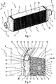
- the figure 2 shows the collector 3, seen at an angle formed between a first longitudinal face 9 and a first side face 11 of the heat exchange body 2.
- the collector 3 comprises a bottom plate receiving one end of the tubes 6, invisible on this figure, surrounded by an edge 13 for securing the lid 4.
- the heat exchange body 2 comprises its plurality of tubes 6 between which is disposed the heat dissipating device 7, for example a interlayer.
- the first lateral face 11 of the heat exchange body 2 is formed by a cheek 14, that is to say a metal plate, particularly rectilinear. Between the end tube 6b and this cheek 14, there is a dissipation device 7 brazed on the cheek and on the longitudinal wall of the end tube 6b.
- the fastening edge 13 is formed by a doubled wall 16, the latter extending all around the heat exchanger 1, that is to say along the two lateral faces and the two longitudinal faces defining the body.
- a doubled wall 16 extending all around the heat exchanger 1, that is to say along the two lateral faces and the two longitudinal faces defining the body.
- this lined wall 16 is formed by a first wall 21 and a second wall 22 brazed against the first wall 21, the lined wall further comprising a fold 23 forming a 180 ° elbow which connects the first wall 21 to the second wall 22.
- the end 17 of the doubled wall 16 is brazed against the longitudinal wall 19 of the end tube or tubes 6a, 6b of the heat exchange body 2. Such brazing occurs on this longitudinal wall in the OX-OY plane, illustrated on the figure 1 .
- the figure 2 also illustrates an exemplary embodiment of the crimping device 8.
- the latter comprises a plurality of crimping tabs 20 which are folded over the heel 15 of the lid 4.
- the crimping tabs 20 come from the first wall 21.
- the figure 3 is a view showing in detail the positioning of the cover 4 in the manifold 3, as well as the connection between this manifold 3 and the end tube 6a or 6b.
- This representation shows a section taken in plane A shown in figure 1 .
- the fastening edge 13 forms a peripheral belt around the bottom plate 24, this fastening edge being preferentially made of material with the bottom plate 24.
- this edge 13 for securing the cover 4 is formed by the doubled wall 16, the latter ending at the end 17 at least partially secured to one or more tubes, in particular on one and / or the other terminal tubes 6a, 6b constituting the heat exchange body 2.
- doubled means that the fastening edge 13 is reinforced by the arrangement of two thicknesses of walls pressed against each other.
- the lined wall 16 is thus formed by a first wall 21 and a second wall 22 immediately adjacent to the first wall 21, and which follows the contours.
- the second wall 22 is rendered at least partially integral with the first wall 21 by a solder between these two walls.
- the first wall 21 is also secured to the second wall 22 by means of a fold.
- the first wall 21 and the second wall 22 come from a same metal sheet which has been bent at 180 ° at the fold 23 to press the second wall 22 against the first wall 21.
- the second wall 22 is made of material with the first wall 21.
- the second wall 22 may be a part previously distinct from the first wall 21, and attached before brazing against it, so as to form the doubled wall 16 once secured to one another, in particular by soldering .
- a thickness of the doubled wall 16 is at least twice greater than a thickness of the bottom plate 24.
- the thickness of the doubled wall 16 is strictly equal to twice the thickness of the bottom wall 24.
- the thickness of the doubled wall 16 is measured in the direction OX, while the thickness of the bottom plate 24 is measured in a direction OZ, these two directions being represented in this figure.
- the edge 13 for securing the lid 4 delimits at least partly a housing 26 for receiving the heel 15 formed at the edge of the opening of the lid 4.
- the bottom plate 24 is in turn extended by a strip 27 which is extends in a direction at least transverse, and preferably perpendicular to the extension plane of the bottom plate 24, that is to say the plane in which the receiving openings of the ends of tubes 6 extend.
- the housing 26 which receives the heel 15 of the lid is thus bordered on one side by the strip 27 and on the other by the first wall 21 constituting the doubled wall 16.
- the strip 27 is here separated from the longitudinal wall 19 of the end tube 6a, 6b, due to the presence of a collar 25.
- the first wall 21 comprises a first band 28 extended by a first sidewall 29.
- the first band 28 forms the bottom of the housing 26 against which the seal 35 bears.
- the first flank 29 extends at least in part to the right of the housing 26, in particular laterally to it.
- the first band 28 and the first sidewall 29 are particularly flat.
- the mechanical reinforcement device takes the form of a chamfer 30, that is to say say a substantially flat edge and inclined relative to the first band 28 and with respect to the first sidewall 29.
- This chamfer 30 thus connects the first band 28 to the first sidewall 29, this chamfer being an element contributing to the mechanical reinforcement of the joining edge 13 cover 4.
- the second wall 22 of the doubled wall 16 comprises a second band 31 extended by a second flank 32.
- the second band 31 extends in a plane parallel to the plane of extension of the first band 28, these two strips being made integral with each other. one from the other by a brazed connection.
- the second flank 32 extends in a plane parallel to the plane of extension of the first flank 29 and is brazed against it.
- the second band 31 is joined to the second flank 32 by a fillet 33, that is to say a rounded section edge.
- This leave 33 forms a second embodiment of the device for mechanical reinforcement of the doubled wall 16.
- This leave 33 is opposite the chamfer 30, and it is configured to be separated from this chamfer 30, such an arrangement contributing to increasing the mechanical strength of the doubled wall 16.
- the second band 31 and the second sidewall 32 are example dishes.
- This combination of the chamfer 30 with the fillet 33 forms a third variant of the mechanical reinforcement means of the doubled wall 16.
- this mechanical reinforcement device can be formed either only by the chamfer 30, or only by the fillet 33, or by the combination of this chamfer 30 with the fillet 33, such a combination which further makes it possible to increase the mechanical strength of the doubled wall 16.
- the end 17 of the doubled wall 16 is formed by an end portion of the second band 31. According to an embodiment not shown, it is a portion of the second band 31 which is brazed against the end tube 6a, 6b.
- the end 17 comprises a fold 34 oriented so that one or other of the faces delimiting the second band 31 is supported and brazed against the end tube 6a, 6b.
- the fold 34 forms a 90 ° angle facing the heat exchange body 2, that is to say the opposite of the lid 4 secured to the collector 3 concerned.
- the doubled wall 16 comprises a series of crimping tabs 20 formed by portions which extend the first wall 21.
- these crimping tabs 20 are shown before folding on the heel 15 of the lid 4. In the final assembly position, these crimping tabs are pressed against the heel 15 of the cover 4, so as to exert a compressive force against the seal 35.
- each tube 6 is connected to the bottom plate 24 by brazing made at the collar 25.
- the edge 13 for securing the lid is substantially reinforced when a distance referenced D 3 is provided between the bottom plate 24 and the end 17 of the doubled wall 16 brazed against the end tube 6a, 6b.
- a distance is at least 2 mm.
- This distance D 3 is measured, for example, between a face of the bottom plate facing the heat exchange body 2 and a plane passing through a face of the second wall 22 soldered against the first wall 21.
- the distance D 3 is at most equal to 6.5 mm.
- the strip 27 disposed perpendicularly to the bottom plate 24 is brazed against the side wall 18 defining at least one tube 6 of the heat exchange body 2.
- such brazing is performed against the side wall of each tube 6, including the end tubes 6a, 6b.
- This brazing is carried out over a distance referenced D 4 which is minimum equal to 1 mm and maximum equal to 7.5 mm.
- This distance D 4 is measured, for example, between an edge delimiting the opening of the tubes at the bottom plate 24 and a straight line passing through the bottom of the housing 26 delimited by the first band 28 constituting the first wall 21.
- the end 17 of the doubled wall 16 is also secured against the side wall 18 of at least one tube 6, similarly to the solutions described with reference to the figure 3 .
- this brazing of the end 17 is made against the side wall of each tube 6, including the end tubes 6a, 6b
- the heat exchange body 2 and the collector 4 can be made from an aluminum alloy.
- the cover 4 can in turn be made of an aluminum alloy or a synthetic material.
- the heat exchanger 1 described above can be integrated into an intake or exhaust gas cooling system of an internal combustion engine.
- the first fluid is formed by the intake gases, in particular a supercharged air flow
- the second fluid is formed by a flow of air, for example outside the vehicle which receives such a system of air. cooling.
- the heat exchanger 1 is thus arranged so that the second fluid passes through the heat exchange body 2, dissipating the heat generated by the first fluid in the second fluid, by means of the tubes and dissipation devices.
- the second fluid passes through the heat exchange body 2 in a direction perpendicular to, or substantially perpendicular to, the direction of movement of the first fluid in the tubes 6.
Landscapes
- Engineering & Computer Science (AREA)
- Physics & Mathematics (AREA)
- Thermal Sciences (AREA)
- Mechanical Engineering (AREA)
- General Engineering & Computer Science (AREA)
- Geometry (AREA)
- Heat-Exchange Devices With Radiators And Conduit Assemblies (AREA)
- Details Of Heat-Exchange And Heat-Transfer (AREA)
Applications Claiming Priority (2)
| Application Number | Priority Date | Filing Date | Title |
|---|---|---|---|
| FR1254741A FR2991037B1 (fr) | 2012-05-24 | 2012-05-24 | Echangeur de chaleur a collecteur renforce |
| PCT/EP2013/060184 WO2013174720A1 (fr) | 2012-05-24 | 2013-05-16 | Echangeur de chaleur a collecteur renforce |
Publications (2)
| Publication Number | Publication Date |
|---|---|
| EP2856058A1 EP2856058A1 (fr) | 2015-04-08 |
| EP2856058B1 true EP2856058B1 (fr) | 2016-05-04 |
Family
ID=48470954
Family Applications (1)
| Application Number | Title | Priority Date | Filing Date |
|---|---|---|---|
| EP13724231.9A Active EP2856058B1 (fr) | 2012-05-24 | 2013-05-16 | Echangeur de chaleur a collecteur renforce |
Country Status (8)
| Country | Link |
|---|---|
| US (1) | US20150129186A1 (ja) |
| EP (1) | EP2856058B1 (ja) |
| JP (1) | JP6030228B2 (ja) |
| KR (1) | KR101639509B1 (ja) |
| CN (1) | CN104583707B (ja) |
| FR (1) | FR2991037B1 (ja) |
| PL (1) | PL2856058T3 (ja) |
| WO (1) | WO2013174720A1 (ja) |
Cited By (1)
| Publication number | Priority date | Publication date | Assignee | Title |
|---|---|---|---|---|
| US11306982B2 (en) | 2018-05-03 | 2022-04-19 | Mann+Hummel Gmbh | Heat exchanger, air intake system with a heat exchanger, and method for mounting a heat exchanger |
Families Citing this family (7)
| Publication number | Priority date | Publication date | Assignee | Title |
|---|---|---|---|---|
| FR2991038A1 (fr) * | 2012-05-24 | 2013-11-29 | Valeo Systemes Thermiques | Echangeur de chaleur a collecteur renforce |
| FR3026168B1 (fr) * | 2014-09-23 | 2016-10-21 | Valeo Systemes Thermiques | Procede de fabrication d'un echangeur de chaleur. |
| EP3264019A1 (en) * | 2016-06-30 | 2018-01-03 | Valeo Systemes Thermiques | A manifold, in particular for use in a cooler of a cooling system |
| CN109804217B (zh) * | 2016-10-14 | 2024-05-28 | 达纳加拿大公司 | 具有空气动力学特征以改善性能的热交换器 |
| CN106767090A (zh) * | 2016-12-07 | 2017-05-31 | 泰安福星汽车配件有限公司 | 一种加强型散热管及加工工艺 |
| US10302373B2 (en) * | 2017-03-03 | 2019-05-28 | Denso International America, Inc | Heat exchanger |
| DE102020204845A1 (de) * | 2020-04-16 | 2021-10-21 | Mahle International Gmbh | Indirekter Ladeluftkühler |
Family Cites Families (19)
| Publication number | Priority date | Publication date | Assignee | Title |
|---|---|---|---|---|
| US4234041A (en) * | 1978-11-15 | 1980-11-18 | Mccord Corporation | Radiator tank headsheet and method |
| JPS56155391A (en) * | 1980-04-30 | 1981-12-01 | Nippon Denso Co Ltd | Corrugated fin type heat exchanger |
| JPH0249514Y2 (ja) * | 1986-07-22 | 1990-12-26 | ||
| JPH03225197A (ja) * | 1990-01-31 | 1991-10-04 | Showa Alum Corp | 熱交換器 |
| FR2742531B1 (fr) * | 1995-12-13 | 1998-01-30 | Valeo Thermique Moteur Sa | Plaque collectrice d'echangeur de chaleur, procede pour sa fabrication et echangeur de chaleur comprenant une telle plaque collectrice |
| JPH10332293A (ja) * | 1997-06-02 | 1998-12-15 | Mitsubishi Heavy Ind Ltd | 熱交換器 |
| FR2783907B1 (fr) * | 1998-09-25 | 2000-12-22 | Valeo Thermique Moteur Sa | Echangeur de chaleur d'encombrement reduit, en particulier pour vehicule automobile |
| DE20016331U1 (de) * | 2000-09-20 | 2002-02-14 | Autokühler GmbH & Co KG, 34369 Hofgeismar | Wärmeaustauscher |
| US6786275B2 (en) | 2002-05-23 | 2004-09-07 | Valeo Engine Cooling | Heat exchanger header assembly |
| DE102005008409A1 (de) * | 2005-02-24 | 2006-08-31 | Modine Manufacturing Co., Racine | Wärmetauscher mit Rohren und Rippen sowie Herstellungsverfahren |
| US9403204B2 (en) * | 2010-01-29 | 2016-08-02 | Modine Manufacturing Company | Heat exchanger assembly and method |
| JP4760693B2 (ja) * | 2006-12-07 | 2011-08-31 | 株式会社デンソー | 熱交換器 |
| FR2933178A1 (fr) * | 2008-06-26 | 2010-01-01 | Valeo Systemes Thermiques | Echangeur de chaleur et carter pour l'echangeur |
| US20100059215A1 (en) * | 2008-09-11 | 2010-03-11 | Proliance International Inc. | Plate type oil cooler |
| FR2954481B1 (fr) * | 2009-12-18 | 2012-02-03 | Valeo Systemes Thermiques | Echangeur de chaleur |
| US8516701B2 (en) * | 2010-05-12 | 2013-08-27 | Delphi Technologies, Inc. | Manifold bending support and method for using same |
| US20120018135A1 (en) * | 2010-07-20 | 2012-01-26 | Denso Marston Ltd. | Header plate, a heat exchanger, a method of making a header plate and a method of making a heat exchanger |
| WO2012014269A1 (ja) * | 2010-07-26 | 2012-02-02 | 株式会社ゼネシス | 熱交換器システム |
| CN202083271U (zh) * | 2011-04-28 | 2011-12-21 | 中国石油化工股份有限公司 | 一种共沸蒸馏换热器的分配器 |
-
2012
- 2012-05-24 FR FR1254741A patent/FR2991037B1/fr active Active
-
2013
- 2013-05-16 KR KR1020147036205A patent/KR101639509B1/ko active IP Right Grant
- 2013-05-16 US US14/402,789 patent/US20150129186A1/en not_active Abandoned
- 2013-05-16 CN CN201380030759.8A patent/CN104583707B/zh not_active Expired - Fee Related
- 2013-05-16 PL PL13724231.9T patent/PL2856058T3/pl unknown
- 2013-05-16 JP JP2015513107A patent/JP6030228B2/ja not_active Expired - Fee Related
- 2013-05-16 WO PCT/EP2013/060184 patent/WO2013174720A1/fr active Application Filing
- 2013-05-16 EP EP13724231.9A patent/EP2856058B1/fr active Active
Cited By (1)
| Publication number | Priority date | Publication date | Assignee | Title |
|---|---|---|---|---|
| US11306982B2 (en) | 2018-05-03 | 2022-04-19 | Mann+Hummel Gmbh | Heat exchanger, air intake system with a heat exchanger, and method for mounting a heat exchanger |
Also Published As
| Publication number | Publication date |
|---|---|
| FR2991037B1 (fr) | 2014-06-20 |
| FR2991037A1 (fr) | 2013-11-29 |
| JP6030228B2 (ja) | 2016-11-24 |
| KR20150017362A (ko) | 2015-02-16 |
| PL2856058T3 (pl) | 2016-11-30 |
| US20150129186A1 (en) | 2015-05-14 |
| CN104583707A (zh) | 2015-04-29 |
| JP2015520353A (ja) | 2015-07-16 |
| CN104583707B (zh) | 2017-02-22 |
| EP2856058A1 (fr) | 2015-04-08 |
| WO2013174720A1 (fr) | 2013-11-28 |
| KR101639509B1 (ko) | 2016-07-13 |
Similar Documents
| Publication | Publication Date | Title |
|---|---|---|
| EP2856058B1 (fr) | Echangeur de chaleur a collecteur renforce | |
| EP2137477B1 (fr) | Échangeur de chaleur pour gaz | |
| EP2912396B1 (fr) | Échangeur thermique, notamment pour vehicule automobile | |
| EP2856059B1 (fr) | Echangeur de chaleur a collecteur renforce | |
| WO2012119835A1 (fr) | Couvercle d'un boitier d'admission | |
| EP3491317B1 (fr) | Echangeur de chaleur a moyens de renfort des tubes ameliores | |
| FR3039263B1 (fr) | Echangeur de chaleur comprenant un boitier et des moyens pour ameliorer l'etancheite dudit boitier | |
| EP1636533B1 (fr) | Echangeur de chaleur comportant un boitier et un faisceau en tole d'aluminium assembles par brasage | |
| EP3384224B1 (fr) | Échangeur de chaleur pour véhicule automobile comprenant une boîte collectrice | |
| WO2016180474A1 (fr) | Connecteur fluidique pour échangeur thermique pour véhicule automobile | |
| FR3030709A1 (fr) | Echangeur de chaleur | |
| EP3532791B1 (fr) | Plaque collectrice pour échangeur de chaleur de véhicule automobile | |
| FR2935912A1 (fr) | Procede d'assemblage et de brasage de deux pieces munies d'elements d'assemblage. | |
| EP2764317B1 (fr) | Echangeur thermique | |
| EP2469209B1 (fr) | Boîtier d'échangeur de chaleur, échangeur de chaleur muni d'un tel boîtier et module d'admission équipé d'un tel échangeur | |
| WO2014048959A1 (fr) | Echangeur de chaleur, notamment pour vehicule automobile, et procede d'assemblage associe | |
| FR2997486A1 (fr) | Tube d'echangeur de chaleur a moyen de perturbation plat | |
| FR3066013A1 (fr) | Tube d'echange de chaleur et echangeur de chaleur comportant au moins un tel tube | |
| FR2969271A1 (fr) | Boitier d'echangeur de chaleur, echangeur de chaleur muni d'un tel boitier et module d'admission equipe d'un tel echangeur | |
| WO2016097136A1 (fr) | Echangeur de chaleur comprenant des moyens permettant d'ameliorer l'etancheite dudit echangeur de chaleur | |
| WO2020099809A1 (fr) | Tube pour échangeur de chaleur | |
| FR2996297A1 (fr) | Plaque collectrice pour echangeur de chaleur. | |
| EP2877805B1 (fr) | Collecteur pour echangeur de chaleur et echangeur de chaleur comprenant un tel collecteur | |
| FR3020454A1 (fr) | Connecteur fluidique pour echangeur thermique pour vehicule automobile | |
| FR3088710A1 (fr) | Echangeur de chaleur pour vehicule automobile |
Legal Events
| Date | Code | Title | Description |
|---|---|---|---|
| PUAI | Public reference made under article 153(3) epc to a published international application that has entered the european phase |
Free format text: ORIGINAL CODE: 0009012 |
|
| 17P | Request for examination filed |
Effective date: 20141121 |
|
| AK | Designated contracting states |
Kind code of ref document: A1 Designated state(s): AL AT BE BG CH CY CZ DE DK EE ES FI FR GB GR HR HU IE IS IT LI LT LU LV MC MK MT NL NO PL PT RO RS SE SI SK SM TR |
|
| AX | Request for extension of the european patent |
Extension state: BA ME |
|
| DAX | Request for extension of the european patent (deleted) | ||
| GRAP | Despatch of communication of intention to grant a patent |
Free format text: ORIGINAL CODE: EPIDOSNIGR1 |
|
| INTG | Intention to grant announced |
Effective date: 20151123 |
|
| GRAS | Grant fee paid |
Free format text: ORIGINAL CODE: EPIDOSNIGR3 |
|
| GRAA | (expected) grant |
Free format text: ORIGINAL CODE: 0009210 |
|
| AK | Designated contracting states |
Kind code of ref document: B1 Designated state(s): AL AT BE BG CH CY CZ DE DK EE ES FI FR GB GR HR HU IE IS IT LI LT LU LV MC MK MT NL NO PL PT RO RS SE SI SK SM TR |
|
| REG | Reference to a national code |
Ref country code: GB Ref legal event code: FG4D Free format text: NOT ENGLISH |
|
| REG | Reference to a national code |
Ref country code: CH Ref legal event code: EP |
|
| REG | Reference to a national code |
Ref country code: AT Ref legal event code: REF Ref document number: 797303 Country of ref document: AT Kind code of ref document: T Effective date: 20160515 |
|
| REG | Reference to a national code |
Ref country code: IE Ref legal event code: FG4D Free format text: LANGUAGE OF EP DOCUMENT: FRENCH |
|
| REG | Reference to a national code |
Ref country code: DE Ref legal event code: R096 Ref document number: 602013007300 Country of ref document: DE |
|
| REG | Reference to a national code |
Ref country code: ES Ref legal event code: FG2A Ref document number: 2577630 Country of ref document: ES Kind code of ref document: T3 Effective date: 20160718 |
|
| REG | Reference to a national code |
Ref country code: NL Ref legal event code: MP Effective date: 20160504 |
|
| REG | Reference to a national code |
Ref country code: LT Ref legal event code: MG4D |
|
| PG25 | Lapsed in a contracting state [announced via postgrant information from national office to epo] |
Ref country code: NL Free format text: LAPSE BECAUSE OF FAILURE TO SUBMIT A TRANSLATION OF THE DESCRIPTION OR TO PAY THE FEE WITHIN THE PRESCRIBED TIME-LIMIT Effective date: 20160504 Ref country code: NO Free format text: LAPSE BECAUSE OF FAILURE TO SUBMIT A TRANSLATION OF THE DESCRIPTION OR TO PAY THE FEE WITHIN THE PRESCRIBED TIME-LIMIT Effective date: 20160804 Ref country code: LT Free format text: LAPSE BECAUSE OF FAILURE TO SUBMIT A TRANSLATION OF THE DESCRIPTION OR TO PAY THE FEE WITHIN THE PRESCRIBED TIME-LIMIT Effective date: 20160504 Ref country code: FI Free format text: LAPSE BECAUSE OF FAILURE TO SUBMIT A TRANSLATION OF THE DESCRIPTION OR TO PAY THE FEE WITHIN THE PRESCRIBED TIME-LIMIT Effective date: 20160504 |
|
| REG | Reference to a national code |
Ref country code: AT Ref legal event code: MK05 Ref document number: 797303 Country of ref document: AT Kind code of ref document: T Effective date: 20160504 Ref country code: FR Ref legal event code: PLFP Year of fee payment: 4 |
|
| PG25 | Lapsed in a contracting state [announced via postgrant information from national office to epo] |
Ref country code: LV Free format text: LAPSE BECAUSE OF FAILURE TO SUBMIT A TRANSLATION OF THE DESCRIPTION OR TO PAY THE FEE WITHIN THE PRESCRIBED TIME-LIMIT Effective date: 20160504 Ref country code: SE Free format text: LAPSE BECAUSE OF FAILURE TO SUBMIT A TRANSLATION OF THE DESCRIPTION OR TO PAY THE FEE WITHIN THE PRESCRIBED TIME-LIMIT Effective date: 20160504 Ref country code: PT Free format text: LAPSE BECAUSE OF FAILURE TO SUBMIT A TRANSLATION OF THE DESCRIPTION OR TO PAY THE FEE WITHIN THE PRESCRIBED TIME-LIMIT Effective date: 20160905 Ref country code: RS Free format text: LAPSE BECAUSE OF FAILURE TO SUBMIT A TRANSLATION OF THE DESCRIPTION OR TO PAY THE FEE WITHIN THE PRESCRIBED TIME-LIMIT Effective date: 20160504 Ref country code: HR Free format text: LAPSE BECAUSE OF FAILURE TO SUBMIT A TRANSLATION OF THE DESCRIPTION OR TO PAY THE FEE WITHIN THE PRESCRIBED TIME-LIMIT Effective date: 20160504 Ref country code: GR Free format text: LAPSE BECAUSE OF FAILURE TO SUBMIT A TRANSLATION OF THE DESCRIPTION OR TO PAY THE FEE WITHIN THE PRESCRIBED TIME-LIMIT Effective date: 20160805 |
|
| PG25 | Lapsed in a contracting state [announced via postgrant information from national office to epo] |
Ref country code: BE Free format text: LAPSE BECAUSE OF NON-PAYMENT OF DUE FEES Effective date: 20160531 Ref country code: IT Free format text: LAPSE BECAUSE OF FAILURE TO SUBMIT A TRANSLATION OF THE DESCRIPTION OR TO PAY THE FEE WITHIN THE PRESCRIBED TIME-LIMIT Effective date: 20160504 |
|
| REG | Reference to a national code |
Ref country code: CH Ref legal event code: PL |
|
| PG25 | Lapsed in a contracting state [announced via postgrant information from national office to epo] |
Ref country code: LI Free format text: LAPSE BECAUSE OF NON-PAYMENT OF DUE FEES Effective date: 20160531 Ref country code: CH Free format text: LAPSE BECAUSE OF NON-PAYMENT OF DUE FEES Effective date: 20160531 Ref country code: RO Free format text: LAPSE BECAUSE OF FAILURE TO SUBMIT A TRANSLATION OF THE DESCRIPTION OR TO PAY THE FEE WITHIN THE PRESCRIBED TIME-LIMIT Effective date: 20160504 Ref country code: DK Free format text: LAPSE BECAUSE OF FAILURE TO SUBMIT A TRANSLATION OF THE DESCRIPTION OR TO PAY THE FEE WITHIN THE PRESCRIBED TIME-LIMIT Effective date: 20160504 Ref country code: SK Free format text: LAPSE BECAUSE OF FAILURE TO SUBMIT A TRANSLATION OF THE DESCRIPTION OR TO PAY THE FEE WITHIN THE PRESCRIBED TIME-LIMIT Effective date: 20160504 Ref country code: EE Free format text: LAPSE BECAUSE OF FAILURE TO SUBMIT A TRANSLATION OF THE DESCRIPTION OR TO PAY THE FEE WITHIN THE PRESCRIBED TIME-LIMIT Effective date: 20160504 |
|
| REG | Reference to a national code |
Ref country code: DE Ref legal event code: R097 Ref document number: 602013007300 Country of ref document: DE |
|
| REG | Reference to a national code |
Ref country code: IE Ref legal event code: MM4A |
|
| PG25 | Lapsed in a contracting state [announced via postgrant information from national office to epo] |
Ref country code: SM Free format text: LAPSE BECAUSE OF FAILURE TO SUBMIT A TRANSLATION OF THE DESCRIPTION OR TO PAY THE FEE WITHIN THE PRESCRIBED TIME-LIMIT Effective date: 20160504 Ref country code: AT Free format text: LAPSE BECAUSE OF FAILURE TO SUBMIT A TRANSLATION OF THE DESCRIPTION OR TO PAY THE FEE WITHIN THE PRESCRIBED TIME-LIMIT Effective date: 20160504 |
|
| PLBE | No opposition filed within time limit |
Free format text: ORIGINAL CODE: 0009261 |
|
| STAA | Information on the status of an ep patent application or granted ep patent |
Free format text: STATUS: NO OPPOSITION FILED WITHIN TIME LIMIT |
|
| PG25 | Lapsed in a contracting state [announced via postgrant information from national office to epo] |
Ref country code: MC Free format text: LAPSE BECAUSE OF FAILURE TO SUBMIT A TRANSLATION OF THE DESCRIPTION OR TO PAY THE FEE WITHIN THE PRESCRIBED TIME-LIMIT Effective date: 20160504 |
|
| 26N | No opposition filed |
Effective date: 20170207 |
|
| REG | Reference to a national code |
Ref country code: FR Ref legal event code: PLFP Year of fee payment: 5 |
|
| PG25 | Lapsed in a contracting state [announced via postgrant information from national office to epo] |
Ref country code: IE Free format text: LAPSE BECAUSE OF NON-PAYMENT OF DUE FEES Effective date: 20160516 Ref country code: SI Free format text: LAPSE BECAUSE OF FAILURE TO SUBMIT A TRANSLATION OF THE DESCRIPTION OR TO PAY THE FEE WITHIN THE PRESCRIBED TIME-LIMIT Effective date: 20160504 |
|
| GBPC | Gb: european patent ceased through non-payment of renewal fee |
Effective date: 20170516 |
|
| PG25 | Lapsed in a contracting state [announced via postgrant information from national office to epo] |
Ref country code: GB Free format text: LAPSE BECAUSE OF NON-PAYMENT OF DUE FEES Effective date: 20170516 |
|
| REG | Reference to a national code |
Ref country code: FR Ref legal event code: PLFP Year of fee payment: 6 |
|
| PG25 | Lapsed in a contracting state [announced via postgrant information from national office to epo] |
Ref country code: HU Free format text: LAPSE BECAUSE OF FAILURE TO SUBMIT A TRANSLATION OF THE DESCRIPTION OR TO PAY THE FEE WITHIN THE PRESCRIBED TIME-LIMIT; INVALID AB INITIO Effective date: 20130516 |
|
| PG25 | Lapsed in a contracting state [announced via postgrant information from national office to epo] |
Ref country code: MT Free format text: LAPSE BECAUSE OF FAILURE TO SUBMIT A TRANSLATION OF THE DESCRIPTION OR TO PAY THE FEE WITHIN THE PRESCRIBED TIME-LIMIT Effective date: 20160504 Ref country code: LU Free format text: LAPSE BECAUSE OF NON-PAYMENT OF DUE FEES Effective date: 20160516 Ref country code: IS Free format text: LAPSE BECAUSE OF FAILURE TO SUBMIT A TRANSLATION OF THE DESCRIPTION OR TO PAY THE FEE WITHIN THE PRESCRIBED TIME-LIMIT Effective date: 20160504 Ref country code: MK Free format text: LAPSE BECAUSE OF FAILURE TO SUBMIT A TRANSLATION OF THE DESCRIPTION OR TO PAY THE FEE WITHIN THE PRESCRIBED TIME-LIMIT Effective date: 20160504 Ref country code: CY Free format text: LAPSE BECAUSE OF FAILURE TO SUBMIT A TRANSLATION OF THE DESCRIPTION OR TO PAY THE FEE WITHIN THE PRESCRIBED TIME-LIMIT Effective date: 20160504 |
|
| PG25 | Lapsed in a contracting state [announced via postgrant information from national office to epo] |
Ref country code: BG Free format text: LAPSE BECAUSE OF FAILURE TO SUBMIT A TRANSLATION OF THE DESCRIPTION OR TO PAY THE FEE WITHIN THE PRESCRIBED TIME-LIMIT Effective date: 20160504 |
|
| PG25 | Lapsed in a contracting state [announced via postgrant information from national office to epo] |
Ref country code: AL Free format text: LAPSE BECAUSE OF FAILURE TO SUBMIT A TRANSLATION OF THE DESCRIPTION OR TO PAY THE FEE WITHIN THE PRESCRIBED TIME-LIMIT Effective date: 20160504 |
|
| PGFP | Annual fee paid to national office [announced via postgrant information from national office to epo] |
Ref country code: CZ Payment date: 20210419 Year of fee payment: 9 |
|
| PGFP | Annual fee paid to national office [announced via postgrant information from national office to epo] |
Ref country code: TR Payment date: 20210506 Year of fee payment: 9 Ref country code: PL Payment date: 20210429 Year of fee payment: 9 Ref country code: ES Payment date: 20210607 Year of fee payment: 9 |
|
| PGFP | Annual fee paid to national office [announced via postgrant information from national office to epo] |
Ref country code: FR Payment date: 20220530 Year of fee payment: 10 Ref country code: DE Payment date: 20220511 Year of fee payment: 10 |
|
| PG25 | Lapsed in a contracting state [announced via postgrant information from national office to epo] |
Ref country code: CZ Free format text: LAPSE BECAUSE OF NON-PAYMENT OF DUE FEES Effective date: 20220516 |
|
| REG | Reference to a national code |
Ref country code: ES Ref legal event code: FD2A Effective date: 20230706 |
|
| PG25 | Lapsed in a contracting state [announced via postgrant information from national office to epo] |
Ref country code: ES Free format text: LAPSE BECAUSE OF NON-PAYMENT OF DUE FEES Effective date: 20220517 |
|
| PG25 | Lapsed in a contracting state [announced via postgrant information from national office to epo] |
Ref country code: PL Free format text: LAPSE BECAUSE OF NON-PAYMENT OF DUE FEES Effective date: 20220516 |
|
| REG | Reference to a national code |
Ref country code: DE Ref legal event code: R119 Ref document number: 602013007300 Country of ref document: DE |
|
| PG25 | Lapsed in a contracting state [announced via postgrant information from national office to epo] |
Ref country code: DE Free format text: LAPSE BECAUSE OF NON-PAYMENT OF DUE FEES Effective date: 20231201 |
|
| PG25 | Lapsed in a contracting state [announced via postgrant information from national office to epo] |
Ref country code: FR Free format text: LAPSE BECAUSE OF NON-PAYMENT OF DUE FEES Effective date: 20230531 |