EP2855830B1 - Vorrichtung und verfahren zur handhabung von bohrstrangkomponenten in einer bohrvorrichtung und bohrvorrichtung - Google Patents
Vorrichtung und verfahren zur handhabung von bohrstrangkomponenten in einer bohrvorrichtung und bohrvorrichtung Download PDFInfo
- Publication number
- EP2855830B1 EP2855830B1 EP13794089.6A EP13794089A EP2855830B1 EP 2855830 B1 EP2855830 B1 EP 2855830B1 EP 13794089 A EP13794089 A EP 13794089A EP 2855830 B1 EP2855830 B1 EP 2855830B1
- Authority
- EP
- European Patent Office
- Prior art keywords
- drill string
- string component
- drill
- gripped
- component
- Prior art date
- Legal status (The legal status is an assumption and is not a legal conclusion. Google has not performed a legal analysis and makes no representation as to the accuracy of the status listed.)
- Active
Links
Images




Classifications
-
- E—FIXED CONSTRUCTIONS
- E21—EARTH OR ROCK DRILLING; MINING
- E21B—EARTH OR ROCK DRILLING; OBTAINING OIL, GAS, WATER, SOLUBLE OR MELTABLE MATERIALS OR A SLURRY OF MINERALS FROM WELLS
- E21B15/00—Supports for the drilling machine, e.g. derricks or masts
- E21B15/003—Supports for the drilling machine, e.g. derricks or masts adapted to be moved on their substructure, e.g. with skidding means; adapted to drill a plurality of wells
-
- E—FIXED CONSTRUCTIONS
- E21—EARTH OR ROCK DRILLING; MINING
- E21B—EARTH OR ROCK DRILLING; OBTAINING OIL, GAS, WATER, SOLUBLE OR MELTABLE MATERIALS OR A SLURRY OF MINERALS FROM WELLS
- E21B17/00—Drilling rods or pipes; Flexible drill strings; Kellies; Drill collars; Sucker rods; Cables; Casings; Tubings
- E21B17/02—Couplings; joints
- E21B17/04—Couplings; joints between rod or the like and bit or between rod and rod or the like
- E21B17/042—Threaded
-
- E—FIXED CONSTRUCTIONS
- E21—EARTH OR ROCK DRILLING; MINING
- E21B—EARTH OR ROCK DRILLING; OBTAINING OIL, GAS, WATER, SOLUBLE OR MELTABLE MATERIALS OR A SLURRY OF MINERALS FROM WELLS
- E21B19/00—Handling rods, casings, tubes or the like outside the borehole, e.g. in the derrick; Apparatus for feeding the rods or cables
- E21B19/16—Connecting or disconnecting pipe couplings or joints
-
- E—FIXED CONSTRUCTIONS
- E21—EARTH OR ROCK DRILLING; MINING
- E21B—EARTH OR ROCK DRILLING; OBTAINING OIL, GAS, WATER, SOLUBLE OR MELTABLE MATERIALS OR A SLURRY OF MINERALS FROM WELLS
- E21B19/00—Handling rods, casings, tubes or the like outside the borehole, e.g. in the derrick; Apparatus for feeding the rods or cables
- E21B19/20—Combined feeding from rack and connecting, e.g. automatically
-
- E—FIXED CONSTRUCTIONS
- E21—EARTH OR ROCK DRILLING; MINING
- E21B—EARTH OR ROCK DRILLING; OBTAINING OIL, GAS, WATER, SOLUBLE OR MELTABLE MATERIALS OR A SLURRY OF MINERALS FROM WELLS
- E21B7/00—Special methods or apparatus for drilling
- E21B7/04—Directional drilling
- E21B7/046—Directional drilling horizontal drilling
Definitions
- the invention relates to a device and a method for handling drill string components in respect of a drill rig, said device including gripping means for gripping a first drill string component to be threaded on to or off from a second drill string component being including in a drill string which is partly drilled into a rock formation.
- the invention also relates to a drill rig including such a device.
- US 6,634,443 B1 is an example of the background art. This document describes a handing device for drill string components, wherein drill string components to be joined to the drill string are transferred between a loading position and a drill string position.
- the invention has as an aim to provide a device and a method according to the above which allow more secure and more efficient handling of drill string components in respect of a drill rig such that in particular the complete procedure during taking up and lowering the drill string into the drill hole can be made less subjected to upcoming problematic situations whereby totally more effective drilling can be preformed.
- the handling unit includes auxiliary engagement means for engagement with second drill string component being partly drilled into the drill hole in the drill string position, that the handling unit with said auxiliary engagement means is adapted for guiding and aligning said gripped first drill string component to be essentially in line with an axial direction defined by said second drill string component, and that the handling unit includes means for variation of angle of said gripping means and thereby said gripped first drill string component in respect of said support means in order to allow said alignment in the drill string position.
- a first drill string component being intended for joining is really aligned with the uppermost drill string component of the drill string being in the drill hole, such that in practice, aligned screw joining can be obtained which results in that threading together in fact is performed as intended and that the sensitive threaded portions of the drill string components are not unnecessarily subjected to oblique loads and thereby damages.
- said auxiliary engagement means are advantageously arranged to engage portions of the second drill string component being located at an axial distance from each other or with at least a certain axial extension, for an alignment to be practically achieved when engagement with a second drill string component is initiated.
- a variant of said auxiliary engagement means is suitably one single clamping means having clamping surfaces from the group: engagement elements such as clamping ridges positioned at a distance from each other as seen in an axial direction of a gripped drill string component, engagement elements that extend over a portion of a gripped drill string component seen in the axial direction, such as jaws having a width, seen in said axial direction, which in general at least corresponds to the diameter of a drill string component.
- said auxiliary engagement means is comprised of two or more manoeuvrable clamping means positioned at a distance from each other.
- said alignment can be obtained with a high degree of security without having to use great application forces or clamping forces.
- said means for variation of angle include joint means with play or flex between parts involved and particularly that said joint means are constructed with play or flex in radial direction such that distances between two elements are variable, and/or with resilience in rotational direction between the parts involved, which gives the possibility of a simple construction wherein said distances can be increased with simple means if necessary.
- said means for variation of angle includes a divided support arm which is positioned between said support means and gripping means, and which includes at least one elastic element between parts of the support arm.
- This solution allows a simpler construction and as an example can be taken elastic elements between the parts of the support arm being comprised of at least one ring-shaped elastic bushing of a rubber or plastic material. Each bushing can then be inserted into a recess in the one support arm portion such that its outer envelopes surface lies against an inner surface in the recess. against an inner surface of the bushing lies a pin which is rigidly joined to the second support arm portion.
- Said support means preferably includes a rigid frame body which carries a rotation actuator in the form of a swing motor for pivoting the handling unit between the drill string position and the loading position.
- auxiliary engagement means and said gripping means are attached on a common carrier, which to a high degree facilitates alignment.
- This carrier contributes together with said auxiliary engagement means and said gripping means in the angling variation in respect of said frame body.
- Said gripping means suitably includes rotation wheels for rotation threading, wherein the rotation can be controlled for threading together or threading apart of the respective components.
- Said gripping means are arranged to provide a gripped first drill string component with an axial movement in connection with it being treaded together with or be threaded apart from a second drill string component such that the rotation is related to the axial movement in order to be adapted to the pitch of the thread in question.
- a support means includes a slide beam being arranged essentially in parallel with a feed beam of the drill rig, and whereon a slide is drivable to and fro, wherein the handling unit is connected to this slide.
- the handling unit is movably connected to said slide over an angling arrangement including a rotation motor with a rotational axis being positioned in a plane perpendicular to a longitudinal axis of the slide beam, for swinging the handling unit with a gripped drill string component between a position in parallel with the drill string position and a horizontal loading position.
- a method according to the invention for handling drill string component in a drill rig is distinguished in that auxiliary engagement means, being included in the handling unit, in the drill string position are brought to engage said second drill string component, that said gripped first drill string component of said auxiliary engagement means is controlled and aligned to essentially in line with an axial direction defined of said second drill string component, and that said gripping means and thereby said gripped first drill string component is imparted said alignment by allowing angling variation in respect of said rigid frame body.
- a drill rig according to the invention includes an inventive handling device.
- Fig. 1 shows a drill rig 1 for core drilling being supported by a support structure S, said drill rig as usual being equipped with a feed beam 3, a carriage 5 being drivable back and forth and having a rotator for driving and rotating a drill string with an upper second drill string component 12 and a lower drill string holder 6.
- FIG. 7 indicate a support means comprising a frame body for fastening a device 2 for handling drill string components (named handling device) on the rig.
- Connecting beams 7' and 7" are arranged for fastening a support means 7 in the regions of the upper and lower ends of the feed beam 3.
- the support means 7 in the shown example includes a tubular body, wherein a swing device is arranged, which in turn includes a swing motor 13 and a swing shaft 14.
- the swing shaft is connected to the support means 7 with the aid of fastening ears with swing bearings for said swing shaft 14.
- the tube-formed body being a support means is arranged sideways of and (with a central axis) in parallel to the feed beam.
- the handling device 2 includes gripping means (globally indicated with 9) for gripping a first drill string component 10 to be put into a drill string position D in the rig or to be taken out from the rig for subsequent positioning in a magazine.
- Reference numeral 29 relates to a support which is rigidly applied at an upper region of the support means 7 for support and for assistance during positioning of the first drill string component 10 in the position shown in Fig. 1 , which is named loading position L.
- the handling device 2 also includes auxiliary engagement means (globally indicated with 11) being intended to engage with a second drill string component 12, in an outermost part thereof, being uppermost in the drill string being drilled into the rock in the drill string position D and somewhat protruding from the rotator 4 in a manner which will be explained below.
- auxiliary engagement means (globally indicated with 11) being intended to engage with a second drill string component 12, in an outermost part thereof, being uppermost in the drill string being drilled into the rock in the drill string position D and somewhat protruding from the rotator 4 in a manner which will be explained below.
- Fig. 2 the rig 1 is shown with a handling device 2 in a second position, wherein the first drill string component 10 is in the drill string position D, that is in a position when the first drill string component 10 as well as the second drill string component 12 being uppermost in the drill string is in the drill string position D.
- the auxiliary engagement means (globally indicated with 11) now have come into engagement with a second drill string component 12.
- first auxiliary engagement means named 11' being outermost on the existing drill string, is shown in engagement with the portion of the drill string component 12 protruding from the rotator 4.
- 11" indicates a second auxiliary engagement means, which is positioned for engagement with the second drill string component 12 in a space between the rotator 4 and the lower holder 6.
- auxiliary engagement means 11' and 11" there is actively obtained an alignment of a longitudinal, here shown tubular, holder for a handling unit 8, which includes said holder and said auxiliary engagement means 11' and 11" as well as also the gripping means 9, which in this embodiment includes two gripping means 9' and 9" being positioned at a distance from each other as seen in an axial direction of a gripped drill string component. Since the gripping means 9' and 9" are still in engagement with the first drill string component 10 said mutual alignment of the drill string components 10 and 12 is hereby initiated.
- auxiliary engagement means 11' and 11" will thereby provide an appropriate alignment of the first drill string component 10 with a second drill string component 12 for a subsequent threading operation.
- Fig. 3 shows the rig with the feed beam in a position where it is essentially parallel to the support structure S of the rig 1 and wherein the rotator and other elements for clarity are removed from the position between the auxiliary engagement means 11' and 11" from the position being indicated with an interrupted arrow at reference number 4.
- Said gripping means 9 can as alternative to include two separated gripping means 9' and 9" be in the form of one single clamping and holder device (not shown) which has a sufficient extension seen in an axial direction of a gripped drill string component for the stability to be maintained.
- a clamping and holder device is combined with at least one support for a gripped drill string component arranged at a distance from the very gripping means.
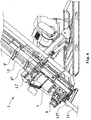
- Fig. 4 shows the area of the gripping means 9' and 9" and the auxiliary engagement means 11' and 11" in greater detail. It is apparent that each gripping means 9' and 9" includes a rigid jaw and a movable jaw which is manoeuvrable for opening and closing with the aid of a respective hydraulic cylinder. Outermost on each jaw there are rotation rollers (not shown on the movable jaws) and inside each gripping means there is also a rotation wheel 18' and 18" respectively, which are rotationally driven by way of a respective rotation motor 19' and 19".
- the first drill string component 10 In closed position of the first jaw of each gripping means 9' and 9", the first drill string component 10 lies in three points against respective gripping means, viz. against the rotation wheels outermost on the jaws and against the rotation wheel. This results in that the drill string component 10 can be rotation during initiation of the rotation motors 19' and 19" for the purpose of thread joining and separating of the first drill string component 10 in respect of the second drill string component 12.
- gripping means 9' and 9" are carried axially movable in respect of the auxiliary engagements 11' and 11".
- the gripping means 9' and 9" are attached axially movable in respect of a holder shaft 16 over a sleeve 20.
- This holder shaft 16 comprises the above mentioned tubular holder for the handling unit 8.
- the gripping means 9' and 9" are further supported over respective axially movable auxiliary sleeves on an additional strut extending in parallel to the holding shaft, comprising an intermediate axis 15 of the handling device 2.
- the gripping means 9' and 9" can be parallel-displaced in respect of the auxiliary engagement means and the displacement be driven by a hydraulic cylinder 79.
- each one of the auxiliary engagement means 11' and 11" includes a rigid and a movable jaw, wherein the movable jaws are manoeuvrable by way of hydraulic cylinders.
- the auxiliary engagement means do not include any rotation rollers as a contrast to the gripping means.
- the intermediate shaft 15 which in the shown embodiment is firmly connected to the holder shaft 16 over swing arms 23 being positioned at an axial distance from each other.
- the intermediate shaft 15 extents through two axially separated resilient yielding hubs, here named flex hubs 22, being supported by a respective swing ear 21 being rigidly connected to the swing arm 14.
- the flex hubs 22 allow radial flex of the intermediate shaft 15 in respect of a body of the hub, allowing angular deviation between the intermediate shaft 15 and the swing shaft 14 and thereby between the holder shaft 16 for the gripping means respectively the auxiliary engagement means and the support means 7 and thereby the feed beam 3 of the rig.
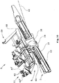
- the flex hubs 22 also allows a rotational yield, which is against action of a spring means (one shown and indicated with 25 in Fig. 5 ) adapted to be fastened to holders 26 between the holder shaft 16 and the intermediate shaft 15, said spring means being removed on Fig. 4 for increased clarity.
- a spring means one shown and indicated with 25 in Fig. 5 ) adapted to be fastened to holders 26 between the holder shaft 16 and the intermediate shaft 15, said spring means being removed on Fig. 4 for increased clarity.
- Fig. 5 shows in greater detail the construction of the means 17 for variation of angle, wherein it is understood that a flex hub 22 is supported with an inner bearing sleeve 27 carried over radial spring means 28 distributed peripherally within an outer bearing sleeve for allowing the radial flex for obtaining that the holder shaft 16 in this section can be displaced a certain distance in respect of the swing shaft 14.
- the rotation of the intermediate shaft 15 in respect of the flex hubs 22 is against action of the spring means 25, wherein the centre distance between the holder shaft 16 and the swing shaft 14 can be altered further.
- the gripping means as well as the auxiliary engagement means can be constructed otherwise and also be arranged to engage the respective drill string component in another way.
- said auxiliary engagement means are two or more activatable clamping means at a distance from each other.
- any or all of the auxiliary engagement means are guiding means without clamping functions in the form of elements with guiding recesses for guiding engagement with and alignment with the drill string components in question, for example when pressing the handling unit in the direction of the drill string component such that the gripped first drill string component will become properly aligned and secure threading together can be achieved.
- Such guiding recesses can have U-shaped, V-shaped, L-shaped etc.
- drill string components being drill tubes
- the invention is applicable also in other types of drilling where the drill string is comprised of threaded drill string components.
- drill string components being part of a drill string, such as lifting plugs and various other elements can, of course, be handled by the inventive device.
- auxiliary engagement means An example of different positioning of auxiliary engagement means is given in Fig. 6 , wherein in the Figure a lower or forward auxiliary engagement means is positioned for engagement with a second drill string component in front of the lower holder 6, whereas in Fig. 7 it is shown that the positioning of the forward or in the Figure lower auxiliary engagement means 11" at a smaller distance from, but adjacent to the upper auxiliary engagement means 11' on the second drill string component 12 protruding from the rotator 4.
- An advantage with the arrangement according to Figs. 6 and 7 in respect of the one in Figs. 1 , 2 etc. is that deeper drilling is allowed in these cases since the rotator can be driven all the way to the holder 6.
- auxiliary engagement means 11' and 11" are arranged for engagement at such a great distance from each other with the second drill string component 12, that adequate alignment can be had. Further, it is of course essential that there is a flexibility in the connection of the part of the handling device 2 which carries the gripping means respectively the auxiliary engagement means in respect of the rig such that a redirection according to the above to align with a real direction of the second drill string component is obtained.
- Fig. 8 diagrammatically illustrates a method sequence, wherein:
- the steps in the positions 33 - 35 are overlapping. Further steps such as thread driving, tightening etc will be performed in the actual use of a handling device according to the invention. The corresponding sequence is applicable for removing drill string components from the rig.
- Fig. 9 shows in a perspective view a drill rig 1 equipped with an alternative device according to the invention.
- the support means 7 includes a slide beam 37 being essentially parallel with the feed beam 3 of the drill rig and having a slide 38 being drivable to and fro, wherein the handling unit is connected to said slide.
- the handling unit 8 is movably connected to said slide 38 over an angling arrangement which includes a rotational motor 39 (shown in this embodiment according to Fig. 10 ) with a rotational axis 40 ( Fig.
- the rotational motor 39 can be oriented otherwise in respect of the slide than what is shown on Figs. 9 and 10 with maintaining the rotational axis 40 in a plane at a right angle to a longitudinal axis of the slide beam 37.
- Fig. 10 shows a variant of said auxiliary engagement means 11 in the form of one single clamping means with a movable jaw 41' and rigid jaw 41".
- clamping surfaces which are constructed as clamping ridges 42 (shown on the movable jaw 41') positioned at a distance from each other as seen in an axial direction of a gripped drill string component.
- FIG. 9 A plurality of components in Figs. 9 and 10 essentially correspond to the above described corresponding components in Figs. 1-7 , which can be consulted for understanding.
- a rotational actuator for swinging the handling unit 8 between the drill string position and the loading position is indicated with 13 ( Fig. 9 ).
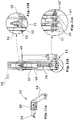
- Figs. 11a, b, c and d show in greater detail said means for variation of angle, which includes a divided support arm 43 positioned between said support means 7 and said gripping means as well as an auxiliary support arm 48 (see also Fig. 9 ).
- the support arm 43 includes in this embodiment two elastic elements positioned between the parts 44 and 45 of the support arm 43.
- Said elastic element between the parts of the support arm here includes two ring-shaped elastic bushings 46 of a rubber or plastic material between an outer and an inner metal ring.
- Each bushing 46 is inserted into a recess in the one support arm part 44 such that its outer envelope surface lies against an inner surface in the recess.
- a pin 47 in the form of a screw, which is rigidly joined to the second support arm part 45, which in this case is comprised of two fastening ears 45', which enclose a first support arm part.
- the second support arm part 45 is rigidly joined with first ends of suitably tubular parallel struts 49 and 50 corresponding to the holder shaft 16 and the intermediate shaft 15 in the embodiment according to Fig. 4 .
- Rigidly joined to second ends of the parallel struts 49 and 50 is a cross strut 51.
- the cross strut forms a rigid, essentially rectangular frame together with the parallel struts 49 and 50 and with a second support arm part 45.
- a guiding pin 52 is arranged on the cross strut 51 for together with a guiding recess 3, here in the form of a circular hole in the auxiliary support arm 48, forming an arrangement for play and flex limitation for said means for variation of angle.
- 54 indicates an elastic means for controlling said play and flex limitation.
- the elastic means 54 acts between the guiding pin and the auxiliary support arm and is here comprised of a conical spring.
- Alternative elastic means for controlling said play and flex limitation can be envisaged and be inserted between the cross strut 51 and the auxiliary support arm 48.
- 79 indicates a cylinder, which acts in a manner corresponding to what is described with reference to Fig. 4 for displacement of the gripping means 9, 9' and 9" respectively, in order to obtain axial movement of these elements corresponding to what is explained in connection with said Fig. 4 .
Landscapes
- Engineering & Computer Science (AREA)
- Life Sciences & Earth Sciences (AREA)
- Geology (AREA)
- Mining & Mineral Resources (AREA)
- Mechanical Engineering (AREA)
- Physics & Mathematics (AREA)
- Environmental & Geological Engineering (AREA)
- Fluid Mechanics (AREA)
- General Life Sciences & Earth Sciences (AREA)
- Geochemistry & Mineralogy (AREA)
- Earth Drilling (AREA)
Claims (15)
- Vorrichtung (2) zur Handhabung von Bohrstrangkomponenten (10) in Bezug auf eine Bohrvorrichtung (1), wobei die Vorrichtung Folgendes umfasst:- ein Greifmittel (9) zum Ergreifen einer ersten Bohrstrangkomponente (10), die auf eine zweite Bohrstrangkomponente (12) aufgezogen oder von dieser abgezogen werden soll, wobei die zweite Bohrstrangkomponente (12) Teil eines Bohrstrangs ist, der zum Teil in eine Felsformation gebohrt ist,- ein Stützmittel (7), um die Vorrichtung zur Handhabung von Bohrstrangkomponenten an der Bohrvorrichtung (1) zu befestigen,- eine Handhabungseinheit (8), die auf bewegbare Weise mit dem Stützmittel (7) verbunden ist und das Greifmittel (9) umfasst und die zwischen einer Bohrstrangstellung (D), in der eine ergriffene erste Bohrstrangkomponente (10) zum Aufziehen auf die zweite Bohrstrangkomponente (12) und Abziehen von dieser positioniert ist, und einer Ladestellung (L), in der eine Bohrstrangkomponente in das Greifmittel eingesetzt oder aus diesem entfernt werden kann, bewegbar ist,dadurch gekennzeichnet,- dass die Handhabungseinheit (8) ein Hilfseingriffsmittel (11, 11', 11") zum Eingriff mit der zweiten Bohrstrangkomponente (12) in der Bohrstrangstellung (D) umfasst,- dass die Handhabungseinheit (8) mit dem Hilfseingriffsmittel (11, 11', 11") geeignet ist, die ergriffene erste Bohrstrangkomponente (10) so zu führen und auszurichten, dass sie sich im Wesentlichen in einer Linie mit einer axialen Richtung befindet, die durch die zweite Bohrstrangkomponente (12) festgelegt ist, und- dass die Handhabungseinheit (8) ein Mittel (17) umfasst, um einen Winkel des Greifmittels und dadurch die ergriffene erste Bohrstrangkomponente (10) in Bezug auf das Stützmittel (7) zu verändern, um die Ausrichtung in der Bohrstrangstellung (D) zu ermöglichen.
- Vorrichtung nach Anspruch 1, dadurch gekennzeichnet, dass das Hilfseingriffsmittel (11, 11', 11") geeignet ist, in Teile der zweiten Bohrstrangkomponente (12) einzugreifen, die in einem axialen Abstand voneinander positioniert sind.
- Vorrichtung nach Anspruch 1 oder 2, dadurch gekennzeichnet, dass das Hilfseingriffsmittel (11, 11', 11") aus zwei oder mehr aktivierbaren Klemmmitteln besteht, die in einem Abstand voneinander positioniert sind.
- Vorrichtung nach einem der Ansprüche 1 bis 3, dadurch gekennzeichnet, dass das Mittel (17) zum Verändern des Winkels Verbindungsmittel (22) mit Spiel oder Biegung zwischen Teilen derselben umfasst.
- Vorrichtung nach Anspruch 4, dadurch gekennzeichnet, dass die Verbindungsmittel (22) mit Spiel oder Biegung in radialer Richtung und/oder mit Nachgiebigkeit in Drehrichtung zwischen ihren Teilen ausgebildet sind.
- Vorrichtung nach einem der Ansprüche 1 bis 4, dadurch gekennzeichnet, dass das Mittel (17) zum Verändern des Winkels einen geteilten Stützarm umfasst, der zwischen dem Stützmittel und dem Greifmittel positioniert ist und wenigstens ein elastisches Element zwischen den Teilen des Stützarms umfasst.
- Vorrichtung nach einem der Ansprüche 1 bis 6, dadurch gekennzeichnet, dass das Stützmittel (7) einen starren Körper umfasst, der einen Drehbetätiger (13) zum Schwenken der Handhabungseinheit (8) zwischen der Bohrstrangstellung (D) und der Ladestellung (L) trägt.
- Vorrichtung nach einem der Ansprüche 1 bis 7, dadurch gekennzeichnet, dass die Greifmittel (9, 9', 9" ) Drehrollen (18', 18" ) für eine Einziehdrehung umfassen.
- Vorrichtung nach einem der Ansprüche 1 bis 8, dadurch gekennzeichnet, dass die Greifmittel (9, 9', 9") so angeordnet sind, dass sie eine ergriffene erste Bohrstrangkomponente (10) mit einer axialen Bewegung in Verbindung damit versehen, dass diese auf eine zweite Bohrstrangkomponente (12) aufgezogen oder von dieser abgezogen wird.
- Vorrichtung nach einem der Ansprüche 1 bis 9, dadurch gekennzeichnet, dass das Stützmittel (7) einen Gleitträger umfasst, der im Wesentlichen parallel zu einem Transportträger der Bohrvorrichtung verläuft und auf dem ein Gleitstück hin und her verfahren werden kann, wobei die Handhabungseinheit (8) mit dem Gleitstück verbunden ist.
- Vorrichtung nach Anspruch 10, dadurch gekennzeichnet, dass die Handhabungseinheit (8) auf bewegbare Weise über eine Winkelanordnung mit dem Gleitstück verbunden ist, wobei die Winkelanordnung einen Schwenkmotor aufweist, der eine Schwenkachse aufweist, die in einer zu einer Längsachse des Gleitträgers rechtwinklig verlaufenden Ebene angeordnet ist, um die Handhabungseinheit (8) mit einer ergriffenen Bohrstrangkomponente zwischen einer Stellung (D), in der sie sich parallel zu der Bohrstrangkomponente befindet, und einer horizontalen Ladestellung (L) zu verschwenken.
- Verfahren zur Handhabung von Bohrstrangkomponenten in Bezug auf eine Bohrvorrichtung, wobei das Verfahren folgende Schritte umfasst:- mit Hilfe des Greifmittels (9) Ergreifen einer ersten Bohrstrangkomponente (10), die auf eine zweite Bohrstrangkomponente (12) aufgezogen oder von dieser abgezogen werden soll, wobei die zweite Bohrstrangkomponente (12) Teil eines Bohrstrangs ist, der zum Teil in eine Felsformation gebohrt ist,- Bewegen einer Handhabungseinheit (8), die auf bewegbare Weise mit einem Stützmittel verbunden ist und das Greifmittel umfasst und die zwischen einer Bohrstrangstellung (D), in der eine ergriffene erste Bohrstrangkomponente (10) zum Aufziehen auf die zweite Bohrstrangkomponente (12) und Abziehen von dieser positioniert ist, und einer Ladestellung (L), in der eine Bohrstrangkomponente in das Greifmittel eingesetzt oder aus diesem entfernt werden kann, bewegbar ist,dadurch gekennzeichnet,- dass ein Hilfseingriffsmittel (11, 11', 11"), das in der Handhabungseinheit enthalten ist, dazu gebracht wird, in der Bohrstrangstellung in die zweite Bohrstrangkomponente (12) einzugreifen,- dass die ergriffene erste Bohrstrangkomponente (10) über das Hilfseingriffsmittel so geführt und ausgerichtet wird, dass sie sich im Wesentlichen in einer Linie mit einer axialen Richtung befindet, die durch die zweite Bohrstrangkomponente festgelegt ist, und- dass die Ausrichtung des Greifmittels und dadurch der ergriffenen ersten Bohrstrangkomponente durch das Ermöglichen einer Veränderung des Winkels in Bezug auf das Stützmittel ermöglicht wird.
- Verfahren nach Anspruch 12, dadurch gekennzeichnet, dass das Hilfseingriffsmittel (11, 11', 11") in Teile der zweiten Bohrstrangkomponente (12) eingreift, die in einem axialen Abstand voneinander positioniert sind.
- Verfahren nach Anspruch 12 oder 13,
dadurch gekennzeichnet, dass eine ergriffene erste Bohrstrangkomponente (10) einzuggedreht und mit einer axialen Bewegung in Verbindung damit versehen wird, dass sie auf eine zweite Bohrstrangkomponente (12) aufgezogen oder von dieser abgezogen wird. - Bohrvorrichtung, die eine Trägereinheit (S), einen Transportträger (3) und eine Bohrstrangantriebsvorrichtung (4) umfasst, die auf dem Transportträger hin und her bewegt werden kann, dadurch gekennzeichnet, dass sie eine Vorrichtung nach einem der Ansprüche 1 bis 11 umfasst.
Applications Claiming Priority (2)
| Application Number | Priority Date | Filing Date | Title |
|---|---|---|---|
| SE1250531A SE537525C2 (sv) | 2012-05-25 | 2012-05-25 | Anordning och förfarande för hantering av borrsträngskomponenter vid en borrigg samt borrigg |
| PCT/SE2013/050593 WO2013176618A1 (en) | 2012-05-25 | 2013-05-23 | Device and method for handling drill string components in a drill rig and drill rig |
Publications (3)
| Publication Number | Publication Date |
|---|---|
| EP2855830A1 EP2855830A1 (de) | 2015-04-08 |
| EP2855830A4 EP2855830A4 (de) | 2016-04-27 |
| EP2855830B1 true EP2855830B1 (de) | 2017-08-16 |
Family
ID=49624171
Family Applications (1)
| Application Number | Title | Priority Date | Filing Date |
|---|---|---|---|
| EP13794089.6A Active EP2855830B1 (de) | 2012-05-25 | 2013-05-23 | Vorrichtung und verfahren zur handhabung von bohrstrangkomponenten in einer bohrvorrichtung und bohrvorrichtung |
Country Status (9)
| Country | Link |
|---|---|
| US (1) | US10113374B2 (de) |
| EP (1) | EP2855830B1 (de) |
| KR (1) | KR102076875B1 (de) |
| CN (1) | CN104379866B (de) |
| AU (1) | AU2013266945B2 (de) |
| CA (1) | CA2871299C (de) |
| SE (1) | SE537525C2 (de) |
| WO (1) | WO2013176618A1 (de) |
| ZA (1) | ZA201408937B (de) |
Families Citing this family (18)
| Publication number | Priority date | Publication date | Assignee | Title |
|---|---|---|---|---|
| SE537457C2 (sv) | 2013-08-02 | 2015-05-05 | Atlas Copco Rocktech Ab | Hanteringsanordning för borrsträngskomponenter vid en bergborrigg samt bergborrigg |
| SE537328C2 (sv) | 2013-08-02 | 2015-04-07 | Atlas Copco Rocktech Ab | Anordning för hantering av borrsträngskomponenter samt bergborrigg |
| SE538718C2 (sv) * | 2013-08-02 | 2016-10-25 | Atlas Copco Rock Drills Ab | Anordning för hantering av borrsträngskomponenter vid en bergborrigg och bergborrigg |
| NO20141364A1 (no) * | 2014-11-13 | 2016-05-16 | Dwellop As | Arm for å trekke ut et brønnrør fra en petroleumsbrønn og framgangsmåte for anvendelse av armen |
| US10738545B2 (en) | 2015-12-15 | 2020-08-11 | Prostar Energy Technologies (Usa) Llc | Pipe handler and pipe loader for a well rig |
| AU2017255807B2 (en) * | 2016-04-25 | 2021-12-23 | Usinage Marcotte Inc. | Rod handling system |
| US10400525B2 (en) * | 2016-05-13 | 2019-09-03 | Dr Fabrication Inc. | Rod positioning device |
| WO2019010572A1 (en) * | 2017-07-11 | 2019-01-17 | Les Équipements De Forage Versadrill Inc. | CAROTTER TUBE DISPLACEMENT DEVICE FOR LONG RANGE DRILLING MACHINES |
| CN110067509B (zh) * | 2018-05-15 | 2024-03-15 | 沧州海岳矿山机电设备有限公司 | 可以钻进定向先导孔的反井钻机及定向先导孔的施工工艺 |
| CN109915016B (zh) * | 2019-04-03 | 2024-03-08 | 中国铁建重工集团股份有限公司 | 凿岩台车和凿岩台车控制方法 |
| RU190838U1 (ru) * | 2019-04-23 | 2019-07-15 | федеральное государственное бюджетное образовательное учреждение высшего образования "Кузбасский государственный технический университет имени Т.Ф. Горбачева" (КузГТУ) | Механизм подачи бурошнековой установки для бестраншейной прокладки трубопровода |
| CN110306936B (zh) * | 2019-07-09 | 2021-07-23 | 煤炭科学技术研究院有限公司 | 一种钻屑法专项钻机 |
| US11454069B2 (en) | 2020-04-21 | 2022-09-27 | Schlumberger Technology Corporation | System and method for handling a tubular member |
| US11434706B1 (en) * | 2021-04-13 | 2022-09-06 | 2233381 Alberta Corp. | Pipe handling assembly for use in horizontal directional drilling |
| CN113882812B (zh) * | 2021-08-23 | 2023-12-12 | 重庆宏工工程机械股份有限公司 | 狭窄空间下智能小型竖井钻孔机及钻孔方法 |
| EP4634485A1 (de) * | 2022-12-16 | 2025-10-22 | Boart Longyear Manufacturing and Distribution Inc. | Kernrohrhandhabungssystem mit ausstossablage |
| CN116717191B (zh) * | 2023-08-10 | 2023-10-20 | 山东天河科技股份有限公司 | 一种煤矿钻机稳固装置 |
| CN119062249B (zh) * | 2024-10-08 | 2025-04-15 | 中国矿业大学徐海学院 | 一种矿用定向钻机角度调整装置及其方法 |
Family Cites Families (9)
| Publication number | Priority date | Publication date | Assignee | Title |
|---|---|---|---|---|
| FR2443008A1 (fr) * | 1978-11-29 | 1980-06-27 | Petroles Cie Francaise | Procede d'accostage d'un element tubulaire additionnel sur une structure tubulaire, ainsi que dispositif de mise en oeuvre |
| US7249637B2 (en) * | 1997-09-02 | 2007-07-31 | Weatherford/Lamb, Inc. | Method and device to clamp control lines to tubulars |
| GB2334270A (en) * | 1998-02-14 | 1999-08-18 | Weatherford Lamb | Apparatus for attachment to pipe handling arm |
| AUPP009999A0 (en) | 1999-04-28 | 1999-05-20 | Boart Longyear Pty Ltd | Drill rod handling device |
| US6189620B1 (en) | 2000-07-31 | 2001-02-20 | Mcdowell Bobby Dewain | Method and apparatus for shutting off upward flow from a conduit |
| CN101449024B (zh) * | 2006-04-11 | 2013-06-19 | 朗耶商标有限公司 | 钻杆处理机 |
| US8186926B2 (en) * | 2006-04-11 | 2012-05-29 | Longyear Tm, Inc. | Drill rod handler |
| WO2007115375A1 (en) | 2006-04-11 | 2007-10-18 | Boart Longyear International Holdings, Inc. | Drill rod handler |
| SE534759C2 (sv) * | 2010-04-14 | 2011-12-13 | Atlas Copco Rocktech Ab | Anordning och förfarande för hantering av borrsträngskomponenter samt borrigg |
-
2012
- 2012-05-25 SE SE1250531A patent/SE537525C2/sv unknown
-
2013
- 2013-05-23 AU AU2013266945A patent/AU2013266945B2/en active Active
- 2013-05-23 WO PCT/SE2013/050593 patent/WO2013176618A1/en not_active Ceased
- 2013-05-23 CA CA2871299A patent/CA2871299C/en active Active
- 2013-05-23 CN CN201380027475.3A patent/CN104379866B/zh active Active
- 2013-05-23 US US14/403,783 patent/US10113374B2/en active Active
- 2013-05-23 EP EP13794089.6A patent/EP2855830B1/de active Active
- 2013-05-23 KR KR1020147034976A patent/KR102076875B1/ko active Active
-
2014
- 2014-12-05 ZA ZA2014/08937A patent/ZA201408937B/en unknown
Non-Patent Citations (1)
| Title |
|---|
| None * |
Also Published As
| Publication number | Publication date |
|---|---|
| SE1250531A1 (sv) | 2013-11-26 |
| US10113374B2 (en) | 2018-10-30 |
| SE537525C2 (sv) | 2015-06-02 |
| EP2855830A4 (de) | 2016-04-27 |
| WO2013176618A1 (en) | 2013-11-28 |
| CN104379866B (zh) | 2016-08-24 |
| AU2013266945B2 (en) | 2016-12-15 |
| KR102076875B1 (ko) | 2020-02-13 |
| ZA201408937B (en) | 2016-08-31 |
| CA2871299C (en) | 2020-03-24 |
| AU2013266945A1 (en) | 2014-12-04 |
| US20150136420A1 (en) | 2015-05-21 |
| CA2871299A1 (en) | 2013-11-28 |
| CN104379866A (zh) | 2015-02-25 |
| EP2855830A1 (de) | 2015-04-08 |
| KR20150023385A (ko) | 2015-03-05 |
Similar Documents
| Publication | Publication Date | Title |
|---|---|---|
| US10113374B2 (en) | Device and method for handling drill string components in a drill rig and drill rig | |
| CA2917216C (en) | Device for handling drill string components in respect of a rock drill rig and rock drill rig | |
| AU2009264153B2 (en) | Rock-drilling unit, drill bit changer, and method for changing drill bit | |
| US11828176B2 (en) | Dual-member pipe assembly | |
| BR112013030084B1 (pt) | Conexão para formação ou remoção de um tubo | |
| KR20120033954A (ko) | 헤드부를 갖는 천공장치 | |
| US9790752B2 (en) | Handling device and method for handling drill string components in rock drilling and rock drill rig | |
| CA2727856C (en) | Drill bit magazine, drill bit holder, and method for changing drill bit in rock drilling unit | |
| US9546522B2 (en) | Lead supporting device of drilling machine | |
| EP2659086B1 (de) | Vorrichtung und verfahren zur handhabung von bohrgestängeteilen sowie gesteinsbohrgestell | |
| CN106232933B (zh) | 用于旋转钻机的钻机头的卡盘 | |
| EP3361039A1 (de) | Bohrstrangführungsvorrichtung und verfahren zur verbindung von bohrstrangkomponenten mit solch einer vorrichtung | |
| JP7421714B2 (ja) | 削孔装置 | |
| JP7406187B2 (ja) | 削孔装置 |
Legal Events
| Date | Code | Title | Description |
|---|---|---|---|
| PUAI | Public reference made under article 153(3) epc to a published international application that has entered the european phase |
Free format text: ORIGINAL CODE: 0009012 |
|
| 17P | Request for examination filed |
Effective date: 20141120 |
|
| AK | Designated contracting states |
Kind code of ref document: A1 Designated state(s): AL AT BE BG CH CY CZ DE DK EE ES FI FR GB GR HR HU IE IS IT LI LT LU LV MC MK MT NL NO PL PT RO RS SE SI SK SM TR |
|
| AX | Request for extension of the european patent |
Extension state: BA ME |
|
| DAX | Request for extension of the european patent (deleted) | ||
| RA4 | Supplementary search report drawn up and despatched (corrected) |
Effective date: 20160331 |
|
| RIC1 | Information provided on ipc code assigned before grant |
Ipc: E21B 19/16 20060101ALI20160323BHEP Ipc: E21B 19/20 20060101AFI20160323BHEP Ipc: E21B 7/04 20060101ALI20160323BHEP |
|
| GRAP | Despatch of communication of intention to grant a patent |
Free format text: ORIGINAL CODE: EPIDOSNIGR1 |
|
| INTG | Intention to grant announced |
Effective date: 20170421 |
|
| GRAS | Grant fee paid |
Free format text: ORIGINAL CODE: EPIDOSNIGR3 |
|
| GRAA | (expected) grant |
Free format text: ORIGINAL CODE: 0009210 |
|
| AK | Designated contracting states |
Kind code of ref document: B1 Designated state(s): AL AT BE BG CH CY CZ DE DK EE ES FI FR GB GR HR HU IE IS IT LI LT LU LV MC MK MT NL NO PL PT RO RS SE SI SK SM TR |
|
| REG | Reference to a national code |
Ref country code: GB Ref legal event code: FG4D |
|
| REG | Reference to a national code |
Ref country code: CH Ref legal event code: EP |
|
| REG | Reference to a national code |
Ref country code: IE Ref legal event code: FG4D |
|
| REG | Reference to a national code |
Ref country code: AT Ref legal event code: REF Ref document number: 919229 Country of ref document: AT Kind code of ref document: T Effective date: 20170915 |
|
| REG | Reference to a national code |
Ref country code: DE Ref legal event code: R096 Ref document number: 602013025195 Country of ref document: DE |
|
| REG | Reference to a national code |
Ref country code: NL Ref legal event code: MP Effective date: 20170816 |
|
| REG | Reference to a national code |
Ref country code: LT Ref legal event code: MG4D |
|
| REG | Reference to a national code |
Ref country code: AT Ref legal event code: MK05 Ref document number: 919229 Country of ref document: AT Kind code of ref document: T Effective date: 20170816 |
|
| PG25 | Lapsed in a contracting state [announced via postgrant information from national office to epo] |
Ref country code: NL Free format text: LAPSE BECAUSE OF FAILURE TO SUBMIT A TRANSLATION OF THE DESCRIPTION OR TO PAY THE FEE WITHIN THE PRESCRIBED TIME-LIMIT Effective date: 20170816 Ref country code: SE Free format text: LAPSE BECAUSE OF FAILURE TO SUBMIT A TRANSLATION OF THE DESCRIPTION OR TO PAY THE FEE WITHIN THE PRESCRIBED TIME-LIMIT Effective date: 20170816 Ref country code: LT Free format text: LAPSE BECAUSE OF FAILURE TO SUBMIT A TRANSLATION OF THE DESCRIPTION OR TO PAY THE FEE WITHIN THE PRESCRIBED TIME-LIMIT Effective date: 20170816 Ref country code: AT Free format text: LAPSE BECAUSE OF FAILURE TO SUBMIT A TRANSLATION OF THE DESCRIPTION OR TO PAY THE FEE WITHIN THE PRESCRIBED TIME-LIMIT Effective date: 20170816 Ref country code: NO Free format text: LAPSE BECAUSE OF FAILURE TO SUBMIT A TRANSLATION OF THE DESCRIPTION OR TO PAY THE FEE WITHIN THE PRESCRIBED TIME-LIMIT Effective date: 20171116 |
|
| PG25 | Lapsed in a contracting state [announced via postgrant information from national office to epo] |
Ref country code: BG Free format text: LAPSE BECAUSE OF FAILURE TO SUBMIT A TRANSLATION OF THE DESCRIPTION OR TO PAY THE FEE WITHIN THE PRESCRIBED TIME-LIMIT Effective date: 20171116 Ref country code: PL Free format text: LAPSE BECAUSE OF FAILURE TO SUBMIT A TRANSLATION OF THE DESCRIPTION OR TO PAY THE FEE WITHIN THE PRESCRIBED TIME-LIMIT Effective date: 20170816 Ref country code: RS Free format text: LAPSE BECAUSE OF FAILURE TO SUBMIT A TRANSLATION OF THE DESCRIPTION OR TO PAY THE FEE WITHIN THE PRESCRIBED TIME-LIMIT Effective date: 20170816 Ref country code: ES Free format text: LAPSE BECAUSE OF FAILURE TO SUBMIT A TRANSLATION OF THE DESCRIPTION OR TO PAY THE FEE WITHIN THE PRESCRIBED TIME-LIMIT Effective date: 20170816 Ref country code: LV Free format text: LAPSE BECAUSE OF FAILURE TO SUBMIT A TRANSLATION OF THE DESCRIPTION OR TO PAY THE FEE WITHIN THE PRESCRIBED TIME-LIMIT Effective date: 20170816 Ref country code: IS Free format text: LAPSE BECAUSE OF FAILURE TO SUBMIT A TRANSLATION OF THE DESCRIPTION OR TO PAY THE FEE WITHIN THE PRESCRIBED TIME-LIMIT Effective date: 20171216 Ref country code: GR Free format text: LAPSE BECAUSE OF FAILURE TO SUBMIT A TRANSLATION OF THE DESCRIPTION OR TO PAY THE FEE WITHIN THE PRESCRIBED TIME-LIMIT Effective date: 20171117 |
|
| PG25 | Lapsed in a contracting state [announced via postgrant information from national office to epo] |
Ref country code: CZ Free format text: LAPSE BECAUSE OF FAILURE TO SUBMIT A TRANSLATION OF THE DESCRIPTION OR TO PAY THE FEE WITHIN THE PRESCRIBED TIME-LIMIT Effective date: 20170816 Ref country code: RO Free format text: LAPSE BECAUSE OF FAILURE TO SUBMIT A TRANSLATION OF THE DESCRIPTION OR TO PAY THE FEE WITHIN THE PRESCRIBED TIME-LIMIT Effective date: 20170816 Ref country code: DK Free format text: LAPSE BECAUSE OF FAILURE TO SUBMIT A TRANSLATION OF THE DESCRIPTION OR TO PAY THE FEE WITHIN THE PRESCRIBED TIME-LIMIT Effective date: 20170816 |
|
| REG | Reference to a national code |
Ref country code: DE Ref legal event code: R097 Ref document number: 602013025195 Country of ref document: DE |
|
| PG25 | Lapsed in a contracting state [announced via postgrant information from national office to epo] |
Ref country code: SK Free format text: LAPSE BECAUSE OF FAILURE TO SUBMIT A TRANSLATION OF THE DESCRIPTION OR TO PAY THE FEE WITHIN THE PRESCRIBED TIME-LIMIT Effective date: 20170816 Ref country code: IT Free format text: LAPSE BECAUSE OF FAILURE TO SUBMIT A TRANSLATION OF THE DESCRIPTION OR TO PAY THE FEE WITHIN THE PRESCRIBED TIME-LIMIT Effective date: 20170816 Ref country code: SM Free format text: LAPSE BECAUSE OF FAILURE TO SUBMIT A TRANSLATION OF THE DESCRIPTION OR TO PAY THE FEE WITHIN THE PRESCRIBED TIME-LIMIT Effective date: 20170816 Ref country code: EE Free format text: LAPSE BECAUSE OF FAILURE TO SUBMIT A TRANSLATION OF THE DESCRIPTION OR TO PAY THE FEE WITHIN THE PRESCRIBED TIME-LIMIT Effective date: 20170816 |
|
| PLBE | No opposition filed within time limit |
Free format text: ORIGINAL CODE: 0009261 |
|
| STAA | Information on the status of an ep patent application or granted ep patent |
Free format text: STATUS: NO OPPOSITION FILED WITHIN TIME LIMIT |
|
| 26N | No opposition filed |
Effective date: 20180517 |
|
| PG25 | Lapsed in a contracting state [announced via postgrant information from national office to epo] |
Ref country code: SI Free format text: LAPSE BECAUSE OF FAILURE TO SUBMIT A TRANSLATION OF THE DESCRIPTION OR TO PAY THE FEE WITHIN THE PRESCRIBED TIME-LIMIT Effective date: 20170816 |
|
| REG | Reference to a national code |
Ref country code: DE Ref legal event code: R119 Ref document number: 602013025195 Country of ref document: DE |
|
| REG | Reference to a national code |
Ref country code: CH Ref legal event code: PL |
|
| GBPC | Gb: european patent ceased through non-payment of renewal fee |
Effective date: 20180523 |
|
| REG | Reference to a national code |
Ref country code: BE Ref legal event code: MM Effective date: 20180531 |
|
| PG25 | Lapsed in a contracting state [announced via postgrant information from national office to epo] |
Ref country code: MC Free format text: LAPSE BECAUSE OF FAILURE TO SUBMIT A TRANSLATION OF THE DESCRIPTION OR TO PAY THE FEE WITHIN THE PRESCRIBED TIME-LIMIT Effective date: 20170816 |
|
| REG | Reference to a national code |
Ref country code: IE Ref legal event code: MM4A |
|
| PG25 | Lapsed in a contracting state [announced via postgrant information from national office to epo] |
Ref country code: CH Free format text: LAPSE BECAUSE OF NON-PAYMENT OF DUE FEES Effective date: 20180531 Ref country code: LI Free format text: LAPSE BECAUSE OF NON-PAYMENT OF DUE FEES Effective date: 20180531 |
|
| PG25 | Lapsed in a contracting state [announced via postgrant information from national office to epo] |
Ref country code: LU Free format text: LAPSE BECAUSE OF NON-PAYMENT OF DUE FEES Effective date: 20180523 |
|
| PG25 | Lapsed in a contracting state [announced via postgrant information from national office to epo] |
Ref country code: GB Free format text: LAPSE BECAUSE OF NON-PAYMENT OF DUE FEES Effective date: 20180523 Ref country code: DE Free format text: LAPSE BECAUSE OF NON-PAYMENT OF DUE FEES Effective date: 20181201 Ref country code: IE Free format text: LAPSE BECAUSE OF NON-PAYMENT OF DUE FEES Effective date: 20180523 Ref country code: FR Free format text: LAPSE BECAUSE OF NON-PAYMENT OF DUE FEES Effective date: 20180531 |
|
| PG25 | Lapsed in a contracting state [announced via postgrant information from national office to epo] |
Ref country code: BE Free format text: LAPSE BECAUSE OF NON-PAYMENT OF DUE FEES Effective date: 20180531 |
|
| PG25 | Lapsed in a contracting state [announced via postgrant information from national office to epo] |
Ref country code: MT Free format text: LAPSE BECAUSE OF NON-PAYMENT OF DUE FEES Effective date: 20180523 |
|
| PG25 | Lapsed in a contracting state [announced via postgrant information from national office to epo] |
Ref country code: PT Free format text: LAPSE BECAUSE OF FAILURE TO SUBMIT A TRANSLATION OF THE DESCRIPTION OR TO PAY THE FEE WITHIN THE PRESCRIBED TIME-LIMIT Effective date: 20170816 |
|
| PG25 | Lapsed in a contracting state [announced via postgrant information from national office to epo] |
Ref country code: HU Free format text: LAPSE BECAUSE OF FAILURE TO SUBMIT A TRANSLATION OF THE DESCRIPTION OR TO PAY THE FEE WITHIN THE PRESCRIBED TIME-LIMIT; INVALID AB INITIO Effective date: 20130523 Ref country code: HR Free format text: LAPSE BECAUSE OF FAILURE TO SUBMIT A TRANSLATION OF THE DESCRIPTION OR TO PAY THE FEE WITHIN THE PRESCRIBED TIME-LIMIT Effective date: 20170816 Ref country code: MK Free format text: LAPSE BECAUSE OF NON-PAYMENT OF DUE FEES Effective date: 20170816 Ref country code: CY Free format text: LAPSE BECAUSE OF FAILURE TO SUBMIT A TRANSLATION OF THE DESCRIPTION OR TO PAY THE FEE WITHIN THE PRESCRIBED TIME-LIMIT Effective date: 20170816 |
|
| PG25 | Lapsed in a contracting state [announced via postgrant information from national office to epo] |
Ref country code: AL Free format text: LAPSE BECAUSE OF FAILURE TO SUBMIT A TRANSLATION OF THE DESCRIPTION OR TO PAY THE FEE WITHIN THE PRESCRIBED TIME-LIMIT Effective date: 20170816 |
|
| PGFP | Annual fee paid to national office [announced via postgrant information from national office to epo] |
Ref country code: FI Payment date: 20250423 Year of fee payment: 13 |
|
| PGFP | Annual fee paid to national office [announced via postgrant information from national office to epo] |
Ref country code: TR Payment date: 20250429 Year of fee payment: 13 |