EP2855365B1 - Sanitizer system - Google Patents
Sanitizer system Download PDFInfo
- Publication number
- EP2855365B1 EP2855365B1 EP13797529.8A EP13797529A EP2855365B1 EP 2855365 B1 EP2855365 B1 EP 2855365B1 EP 13797529 A EP13797529 A EP 13797529A EP 2855365 B1 EP2855365 B1 EP 2855365B1
- Authority
- EP
- European Patent Office
- Prior art keywords
- ultraviolet
- tube
- air
- ultraviolet lamp
- water
- Prior art date
- Legal status (The legal status is an assumption and is not a legal conclusion. Google has not performed a legal analysis and makes no representation as to the accuracy of the status listed.)
- Not-in-force
Links
- XLYOFNOQVPJJNP-UHFFFAOYSA-N water Substances O XLYOFNOQVPJJNP-UHFFFAOYSA-N 0.000 claims description 99
- CBENFWSGALASAD-UHFFFAOYSA-N Ozone Chemical compound [O-][O+]=O CBENFWSGALASAD-UHFFFAOYSA-N 0.000 claims description 65
- 238000011012 sanitization Methods 0.000 claims description 20
- 239000000126 substance Substances 0.000 claims description 6
- 238000011144 upstream manufacturing Methods 0.000 claims description 3
- 239000010453 quartz Substances 0.000 description 9
- VYPSYNLAJGMNEJ-UHFFFAOYSA-N silicon dioxide Inorganic materials O=[Si]=O VYPSYNLAJGMNEJ-UHFFFAOYSA-N 0.000 description 9
- 230000002070 germicidal effect Effects 0.000 description 8
- 239000000463 material Substances 0.000 description 5
- 229910052782 aluminium Inorganic materials 0.000 description 4
- XAGFODPZIPBFFR-UHFFFAOYSA-N aluminium Chemical compound [Al] XAGFODPZIPBFFR-UHFFFAOYSA-N 0.000 description 4
- QVGXLLKOCUKJST-UHFFFAOYSA-N atomic oxygen Chemical compound [O] QVGXLLKOCUKJST-UHFFFAOYSA-N 0.000 description 3
- 238000010276 construction Methods 0.000 description 3
- QSHDDOUJBYECFT-UHFFFAOYSA-N mercury Chemical compound [Hg] QSHDDOUJBYECFT-UHFFFAOYSA-N 0.000 description 3
- 229910052753 mercury Inorganic materials 0.000 description 3
- 239000000203 mixture Substances 0.000 description 3
- 239000001301 oxygen Substances 0.000 description 3
- 229910052760 oxygen Inorganic materials 0.000 description 3
- 230000005855 radiation Effects 0.000 description 3
- 230000003068 static effect Effects 0.000 description 3
- 230000009182 swimming Effects 0.000 description 3
- MHAJPDPJQMAIIY-UHFFFAOYSA-N Hydrogen peroxide Chemical compound OO MHAJPDPJQMAIIY-UHFFFAOYSA-N 0.000 description 2
- 241000736262 Microbiota Species 0.000 description 2
- 239000003619 algicide Substances 0.000 description 2
- 230000009286 beneficial effect Effects 0.000 description 2
- 239000006172 buffering agent Substances 0.000 description 2
- 238000006243 chemical reaction Methods 0.000 description 2
- -1 clarifier Substances 0.000 description 2
- 150000001875 compounds Chemical class 0.000 description 2
- 238000001816 cooling Methods 0.000 description 2
- 229910001882 dioxygen Inorganic materials 0.000 description 2
- 238000000034 method Methods 0.000 description 2
- 239000003921 oil Substances 0.000 description 2
- 230000003647 oxidation Effects 0.000 description 2
- 238000007254 oxidation reaction Methods 0.000 description 2
- 239000003002 pH adjusting agent Substances 0.000 description 2
- 239000007787 solid Substances 0.000 description 2
- 229910001220 stainless steel Inorganic materials 0.000 description 2
- 239000010935 stainless steel Substances 0.000 description 2
- 230000001954 sterilising effect Effects 0.000 description 2
- 241000894006 Bacteria Species 0.000 description 1
- XNCOSPRUTUOJCJ-UHFFFAOYSA-N Biguanide Chemical compound NC(N)=NC(N)=N XNCOSPRUTUOJCJ-UHFFFAOYSA-N 0.000 description 1
- 229940123208 Biguanide Drugs 0.000 description 1
- 0 CC=CCCC1=CC*C=*1 Chemical compound CC=CCCC1=CC*C=*1 0.000 description 1
- ZAMOUSCENKQFHK-UHFFFAOYSA-N Chlorine atom Chemical compound [Cl] ZAMOUSCENKQFHK-UHFFFAOYSA-N 0.000 description 1
- 230000003139 buffering effect Effects 0.000 description 1
- 239000000460 chlorine Substances 0.000 description 1
- 229910052801 chlorine Inorganic materials 0.000 description 1
- 239000011248 coating agent Substances 0.000 description 1
- 238000000576 coating method Methods 0.000 description 1
- 238000005260 corrosion Methods 0.000 description 1
- 230000007797 corrosion Effects 0.000 description 1
- 230000008878 coupling Effects 0.000 description 1
- 238000010168 coupling process Methods 0.000 description 1
- 238000005859 coupling reaction Methods 0.000 description 1
- 230000000694 effects Effects 0.000 description 1
- 239000012530 fluid Substances 0.000 description 1
- 230000005661 hydrophobic surface Effects 0.000 description 1
- 125000002887 hydroxy group Chemical group [H]O* 0.000 description 1
- TUJKJAMUKRIRHC-UHFFFAOYSA-N hydroxyl Chemical compound [OH] TUJKJAMUKRIRHC-UHFFFAOYSA-N 0.000 description 1
- 230000001678 irradiating effect Effects 0.000 description 1
- 229910052751 metal Inorganic materials 0.000 description 1
- 239000002184 metal Substances 0.000 description 1
- 238000012544 monitoring process Methods 0.000 description 1
- 125000004430 oxygen atom Chemical group O* 0.000 description 1
- 229920001296 polysiloxane Polymers 0.000 description 1
- 150000003839 salts Chemical class 0.000 description 1
- 238000004513 sizing Methods 0.000 description 1
- 230000001360 synchronised effect Effects 0.000 description 1
Images


Classifications
-
- C—CHEMISTRY; METALLURGY
- C02—TREATMENT OF WATER, WASTE WATER, SEWAGE, OR SLUDGE
- C02F—TREATMENT OF WATER, WASTE WATER, SEWAGE, OR SLUDGE
- C02F1/00—Treatment of water, waste water, or sewage
- C02F1/30—Treatment of water, waste water, or sewage by irradiation
- C02F1/32—Treatment of water, waste water, or sewage by irradiation with ultraviolet light
- C02F1/325—Irradiation devices or lamp constructions
-
- C—CHEMISTRY; METALLURGY
- C02—TREATMENT OF WATER, WASTE WATER, SEWAGE, OR SLUDGE
- C02F—TREATMENT OF WATER, WASTE WATER, SEWAGE, OR SLUDGE
- C02F1/00—Treatment of water, waste water, or sewage
- C02F1/72—Treatment of water, waste water, or sewage by oxidation
- C02F1/78—Treatment of water, waste water, or sewage by oxidation with ozone
-
- C—CHEMISTRY; METALLURGY
- C02—TREATMENT OF WATER, WASTE WATER, SEWAGE, OR SLUDGE
- C02F—TREATMENT OF WATER, WASTE WATER, SEWAGE, OR SLUDGE
- C02F2201/00—Apparatus for treatment of water, waste water or sewage
- C02F2201/32—Details relating to UV-irradiation devices
- C02F2201/322—Lamp arrangement
- C02F2201/3221—Lamps suspended above a water surface or pipe
-
- C—CHEMISTRY; METALLURGY
- C02—TREATMENT OF WATER, WASTE WATER, SEWAGE, OR SLUDGE
- C02F—TREATMENT OF WATER, WASTE WATER, SEWAGE, OR SLUDGE
- C02F2201/00—Apparatus for treatment of water, waste water or sewage
- C02F2201/32—Details relating to UV-irradiation devices
- C02F2201/322—Lamp arrangement
- C02F2201/3227—Units with two or more lamps
-
- C—CHEMISTRY; METALLURGY
- C02—TREATMENT OF WATER, WASTE WATER, SEWAGE, OR SLUDGE
- C02F—TREATMENT OF WATER, WASTE WATER, SEWAGE, OR SLUDGE
- C02F2201/00—Apparatus for treatment of water, waste water or sewage
- C02F2201/32—Details relating to UV-irradiation devices
- C02F2201/322—Lamp arrangement
- C02F2201/3228—Units having reflectors, e.g. coatings, baffles, plates, mirrors
-
- C—CHEMISTRY; METALLURGY
- C02—TREATMENT OF WATER, WASTE WATER, SEWAGE, OR SLUDGE
- C02F—TREATMENT OF WATER, WASTE WATER, SEWAGE, OR SLUDGE
- C02F2201/00—Apparatus for treatment of water, waste water or sewage
- C02F2201/78—Details relating to ozone treatment devices
- C02F2201/784—Diffusers or nozzles for ozonation
-
- C—CHEMISTRY; METALLURGY
- C02—TREATMENT OF WATER, WASTE WATER, SEWAGE, OR SLUDGE
- C02F—TREATMENT OF WATER, WASTE WATER, SEWAGE, OR SLUDGE
- C02F2303/00—Specific treatment goals
- C02F2303/04—Disinfection
Definitions
- This application relates generally to water sanitizers, and particularly to a water sanitizer wherein a flow of water is routed through an ultraviolet-transmissive tube, with a plurality of ultraviolet lamps disposed around the tube so that ultraviolet light of both 255nm and 184nm wavelengths is passed into the water flowing through the tube.
- the lamps and tube are mounted in a housing, with a flow of air provided through the housing so that the ultraviolet light also produces ozone, which is also provided to the water flowing through the tube.
- ultraviolet light is used to produce ozone, which in turn is provided to a flow of water in order to sanitize the water.
- US Patent 5,266,215 describes an apparatus where ozone is produced by the ultraviolet lamp that is used for irradiating the water to be treated and the ozone is introduced into the water using a Venturi mixer.
- the present application relates to a water sanitizer comprising at least one ultraviolet lamp and at least a first and second Venturi mixer, as defined in claim 1.
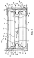
- a reflector 12 may be generally circular, rectangular or in any other convenient shape, and which may also form the housing for the ozone generator.
- a housing may be provided separately from a reflector, and may be formed of a non-reflective material, with one or more reflectors mounted within the housing near inner walls thereof.
- the housing may also be constructed of aluminum in order to dissipate and radiate heat, and may further be provided with heat-radiating fins.
- the reflector 12 is configured to generally focus light from one or more ultraviolet lamps 14 (conventionally connected to electrical power, also not shown) into a tube 16 through which water to be sanitized is flowing.
- reflector 12 may be configured to be parabolic, hyperparabolic, circular or any other shape that focuses or reflects light into tube 16.
- reflector 12 may form an exterior housing of sanitizer 10, such as where the housing is constructed of polished aluminum or polished stainless steel, and as noted, in other instances a separate housing may enclose sanitizer 10, including reflector 12.
- the housing may be omitted entirely, with only a reflector being provided to reflect or direct ultraviolet light as needed.
- Reflector 12 is of a material that reflects at least the 254 nm wavelength of the mercury arc.
- the reflector may be of aluminum, preferably anodized, or TeflonTM coated to prevent corrosion.
- a plurality of ultraviolet lamps may be disposed around tube 16. The number of lamps used may be determined by water flow velocity through tube 16.
- a faster water flow would require more lamps to produce a higher intensity of germicidal ultraviolet light and larger quantity of ozone, which kills or neutralizes any microbiota almost instantly in the water flowing through tube 16, and a slower water flow would require fewer lamps that produce less intense germicidal ultraviolet light and less ozone, but which are still sufficiently intense to kill microbiota in the slower-moving water.
- the ozone is injected into the water flowing through tube 16, as will be further explained.
- Ultraviolet lamp or lamps 14 are ultraviolet lamps that produce intense germicidal ultraviolet light predominantly at 184 nm and 254 nm.
- the 184 wavelength creates ozone.
- the ultraviolet tubes may be about 19 - 30.5 cm (7.5 - 12 inches) long, with the container/housing 12 being about 20.3 - 40.6 cm (8 - 16 inches) long and 7.6 - 12.7 cm (3 - 5 inches) in diameter.
- up to 6 to 8 ultraviolet tubes may be fitted into such a container, and arranged lengthwise around water-carrying tube 16.
- ballasts may be mounted to, in close proximity to or around the exterior of housing 12, or more powerful ballasts configured to drive a plurality of tubes may be used to drive 2 or more ultraviolet lamps.
- the ultraviolet tubes may be 30.5 - 61 cm (12 - 24 inches) or more, with housing 12 sized slightly longer, perhaps by 15.2 - 20.3 cm (6 - 8 inches) or so, and between about 15.2 and 30.5 cm (6 and 12 inches) in diameter.
- the plurality of ultraviolet tubes are clustered around a water-carrying tube 16.
- the ultraviolet tubes would be mounted in close proximity to housing 12 in order to dissipate heat, and housing 12 could be provided with heat-dissipating fins, water channels, one or more cooling fans or the like. Of course, some heat would be carried away by the water flowing through tube 16, but other cooling means may be necessary.
- the ultraviolet tubes may be mounted in close proximity to water-carrying tube 16, such as from about 0.6 to 5 cm (about 0.25 to 2 inches) or so, in order to apply as much ultraviolet light as possible to water-carrying tube 16.
- the ultraviolet tubes As the 184 nm wavelength, which is highly energetic and most effective in germicidal applications, degrades or is absorbed after only a short distance through atmospheric gasses, locating the ultraviolet tubes as close as possible to the water to be sterilized takes full advantage of their energetic properties.
- the transparent housings of the ultraviolet tubes which contain ultraviolet during operation, is of a material, typically pure or ultrapure quartz, that readily passes both the 184 and 255 wavelengths.
- the quartz envelopes of the lamps may be especially made
- the ultraviolet lamp/lamps may be of the hybrid type disclosed in Applicant's US patent no. 6,951,633 , issued 10/04/2005, wherein the exterior of the lamp is wrapped with a wire through which a pulsed voltage, such as a square wave, a spike from a flyback transformer or the like is passed in order to develop a theta pinch on the mercury plasma, and also energize the air in the immediate vicinity of the lamp.
- the theta pinch drives electrons in the mercury plasma away from the inner surface of the quartz walls, which causes the lamps to operate at cooler temperatures, and extends the life of the ultraviolet lamps by reducing collisions of the electrons with the quartz walls, which otherwise would degrade the quartz and reduce efficiency of the quartz in passing UV radiation.
- Tube 16 through which water is flowing may be constructed of any material that is durable, and which allows passage of germicidal ultraviolet light therthrough, such as the aforementioned pure or ultrapure quartz.
- the interior of tube 16 may be coated with a non-stick surface 17, such as one or more of the class of TeflonsTM such as FEP and TFE.
- a non-stick surface 17 such as one or more of the class of TeflonsTM such as FEP and TFE.
- FEP and TFE are also transparent to ultraviolet light.
- tube 16 itself may be fabricated of TFE or FEP.
- germicidal ultraviolet light may be applied directly, by reflection and focusing, to water flowing through tube 16.
- Static mixers 18 may also be fixed in tube 16 in order to create turbulence in the water flowing through tube 16, mixing the water so that as much as possible is exposed to ultraviolet germicidal radiation from lamp/lamps 14.
- Ends 18, 20 serve to enclose ends of the sanitizer, whether against reflector 12 or another exterior housing.
- ends 18, 20 support water tube 16 via Venturis 22, 24, respectively.
- These Venturis may be those as disclosed in Applicant's US patent no. 6,192,911, issued 2/27/2001 , and which are provided with an annular cavity around the motive flow through the Venturi, the cavity communicating with multiple suction ports used to draw fluids and gasses into the motive flow.
- Each of these Venturis are provided with a water inlet port 26 and water outlet port 28, assuming water flow through tube 16 is from right to left, and as stated, multiple suction ports 30.
- the suction ports 30 are oriented near the ultraviolet tube so as to draw ozone directly from the interior of housing 12 into the flow of water through tube 16. This eliminates tubing that would otherwise be necessary to connect an ozone generator to the Venturi. Such a construction also increases the amount of ozone available for sanitization due to greatly reducing the distance the ozone must travel before being put into the water, which in turn reduces the amount of ozone that breaks down and recombines into diatomic oxygen. In addition, by properly sizing the Venturis so that the downstream Venturi 22 has a larger inlet opening, more air flow, and thus more ozone, is created and injected into the water flowing through tube 16.
- one or more of the downstream Venturi suction ports may be reversed and oriented on the outside of housing 12, and connected to a source of other chemicals, such as buffering compounds or compounds used to balance pH.
- a source of other chemicals such as buffering compounds or compounds used to balance pH.
- such as swimming pools using biguanide products as a sanitizer, hydrogen peroxide sanitizer, algicides, Ph adjusting agents, buffering agents and the like may be applied to the pool water via a reversed suction port on one of the Venturis.
- a reversed suction port is seen in the embodiment of Fig. 3 , wherein suction ports 31 are provided to support the addition of chemicals, either in the upstream Venturi 24 or the downstream Venturi 22, or both.
- a single Venturi having multiple suction inlets may be used at the upstream end (Venturi 24) to draw ozonated air directly from the interior of the sanitizer and from near ultraviolet tubes 14 into the flow of water, with the outlet being conventionally supported by end 18.
- Venturi 24 the upstream end
- at least ozone is injected into the water and almost instantly exposed with the water to intense ultraviolet light, creating opportunity for advanced oxidation and other reactions.
- the contact distance for dissolving ozone may be short, so static mixers 19 may be provided in water carrying tube 16. These static mixers create turbulence that breaks up any laminar flow that may develop, and provide a better opportunity for ozone to be mixed in the water and to promote the advanced oxidation and other reactions.
- a mixer of Applicant's design may be substituted for Venturi 22, as will be further explained.
- ballast 34 which may be an electronic ballast, with a cord/strain relief 36 passing through end 20 for connection to electrical power.
- ballasts may be mounted as needed on the outside of the sanitizer, or nearby in one or more separate enclosures.
- a silicone or other suitable seal 38 may be used at each end of water tube 16 to seal between the water tube and the respective Venturi outlet/inlet.
- An air inlet 39 for example in end 20, to allow air to be drawn through the housing is provided, and may be equipped with a filter 40.
- this air is ozonated and drawn into the flow of water directly from the interior of the sanitizer from a region directly around ultraviolet lamps 14.
- openings 41 may be provided to allow free passage of air from near the ultraviolet lamps 14 to the Venturi suction ports 30.
- at least one or more openings 39 may be provided anywhere in enclosure 12 to provide airflow past the ultraviolet lamps 14.
- a window 42 may be provided for optically coupling radiation from lamp/lamps 14 to sensing or monitoring circuitry, or for observation to determine that the lamp/lamps are working.
- the water sanitizer 10 may be connected in series via Venturi inlet 26 and Venturi outlet 28 to any flowing source of water that needs to be sanitized.
- the sanitizer could be connected in a low pressure water circuit for a filter and heater.
- the sanitizer can be connected in a bypass loop wherein pressure differential across the filter develops the motive flow through the Venturi, or in a bypass-type loop configuration wherein the motive flow is powered by at least a scoop on the inlet line of the loop to force water through the loop, as disclosed in Applicant's US patent no. 8,323,511, issued Dec.
- an outlet of the loop may be positioned so that water is drawn from the loop, also as disclosed in the referenced patent.
- saddle clamps may be installed in a primary flow line, and which hold an angled inlet tube to direct water flow through the sanitizer.
- a venturi-like mixer 50 may be used to further mix ozone and water flowing through tube 16.
- water flows through a typical Venturi inlet 52, a constriction 54 and an outlet 56 that is typically several times longer than the inlet.
- a bypass tube or passage 58 is provided, and which extends between a point 60 where the inlet just begins to narrow to a point 62 where the greatest suction from the Venturi occurs.
- mixer 50 supporting one end of the water carrying tube 16
- a portion of the mixture of ozone-containing air and water provided by Venturi 24 that flows through tube 16 and mixer 50 is drawn through bypass 58 and reinjected into the stream of water and ozone-containing air, which creates considerably more turbulence than a second Venturi.
- a froth of air, ozone and water is passed from mixer 50, which may considerably reduce a required contact distance for ozone to dissolve into the water.
- mixer 50 is substituted for the downstream Venturi 22 in Fig. 1 .
- Venturi suction ports 30 are each connected to tubing 62, each of the sections of tubing 62a, 62b connected as shown at each end between respective upper and lower pairs of Venturi suction ports 30.
- Sections of tubing 62a, 62b are positioned to run as shown substantially the entire length of ultraviolet tubes 14, and very close to or even touching tubes 14, with possible spacings being within 0.3 - 1.3 cm (1/8 - 1/2 inch) or so to the surface of tubes 14. In larger designs using larger ultraviolet tubes, this distance may be extended up to about 2.5 - 7.6 cm (1 - 3 inches) or so, depending on the intensity of ultraviolight light emitted from the plasma tube or tubes.
- a multitude of small holes or openings 64 in tubes 62a and 62b extend the length of ultraviolet tubes 14, and may be spaced anywhere from up to about 0.3 - 2.5 cm (1/8 - 1 inch) apart, depending on airflow through tubes 62a and 62b.
- a single slot in an air tube 62a, 62b may run the length of a respective ultraviolet lamp.
- the Venturi suction developed by Venturis 22, 24 is felt inside tubes 62a and 62b, causing air to be drawn into tubes 62a and 62b via the plurality of openings 64 in each of tubes 62a and 62b.
- a compressor 66 may be used to force air through opening 39 in order to pressurize the interior of housing 12 to increase or adjust airflow into openings 64.
- the air drawn or forced into tubes 62a and 62b is air that is in very close proximity to the quartz surface of ultraviolet tubes 14, and thus is enriched in ozone over and above an ozone level obtained from the embodiment of Fig. 1 .
- the 255 nm wavelength propagates through air much better, and in an ozone generator environment is only degraded when impinging an ozone molecule, which absorbs the 255 nm wavelength and breaks down into diatomic oxygen and a free oxygen atom, which in turn quickly combines with atmospheric water vapor to form a hydroxyl radical.
- much of the ozone created in an ultraviolet ozone generator is destroyed before it can be emitted for use. It has been found that more ozone can be obtained from an ultraviolet by drawing the ozone directly from the quartz surface of ultraviolet tubes 14, where the intensity of the 185 nm wavelength is highest and the most ozone is available to be drawn off.
- pulsing of the ultraviolet tubes with a high current, high voltage spike pulse train causes very intense bursts of ultraviolet light in both the 185 nm and 255 nm wavelengths.
- a pulse train would have peak voltages and current greater than what the ultraviolet tube would normally operate on, but would be of very short duration and of a frequency or timing that is synchronized with airflow into openings 64.
- tubes 62a and 62b are about 15 centimeters long and openings 64 are each about 0.06 inches in diameter and spaced about 0.25 inches apart along the length of tubes 62a and 62b. As such, airflow through tubes 62a and 62b is essentially unrestricted.
- tubes 62a and 62b have an internal volume of 18 cubic centimeters, and airflow through each tube is 3 liters per minute, with the tubes 62a and 62b spaced about a centimeter from the plasma tube, it takes about 0.277 seconds to evacuate the air and ozone between a tube 62a, 62b and the ultraviolet tube.
- the plasma tubes may be pulsed about 3 times a second to create an optimum amount of ozone. If the tubes 62a and 62b are 0.5 centimeters from ultraviolet tube 16, then the plasma tubes may be pulsed about 6 times a second to create am optimum amount of ozone.
- the pulses may be high powered pulses of a duration of 5 milliseconds to 20 milliseconds or so.
- the shorter the pulse duration the higher peak power may be applied to the ultraviolet tube. It is contemplated that a peak or instantaneous power of up to 1000 watts per pulse may be used.
- Such high powered pulses also penetrate into the water better than a continuously powered ultraviolet tube. As such, only one or two of these high power pulses are needed to kill bacteria within water flowing through water carrying tube 16.
- water flowing through water carrying tube 16 may be slowed to a rate so that at least one or two high power pulses are applied to organisms therein.
- This process creates ozone molecules between the surface of ultraviolet tube 14 and the nearest opening 64, and allows the newly-created ozone molecules to be drawn into a nearest opening 64 without being destroyed before the next burst of ultraviolet light is generated. Such a process generates significantly more ozone than a conventional ozone generator.
- the desired frequency of pulses for any given rate of air flow into openings 64 can be determined by calculation, or empirically simply by measuring a quantity of ozone in a given air flow rate from the ozone generator at a given frequency of the high current, high voltage pulse train, and adjusting the frequency of the pulse train until the frequency at which a highest level of ozone is produced is determined.
- the frequency of the pulse train may be set, and the air flow rate adjusted until a highest level of ozone generation is measured.
- FIG. 4 shows a cross-section of a ultraviolet tube 70 surrounded by a plurality of tubes 72, which may be constructed of metal, such as aluminum, stainless steel, or an ultraviolet-resistive plastic, such as one of the TeflonTM-type materials, that each have a plurality of openings or a narrow slot 74 extending lengthwise along the length of tubes 72.
- tubes 72 would be located very close to ultraviolet tube 70 in order to draw ozone from the region between openings or slots 74 and the surface of the ultraviolet tube.
- a source of suction may be connected to one or both ends of tubes 72, or to intermediate locations between the ends of tubes 72.
- the embodiment of Fig. 4 may be mounted in a housing, such as shown in Fig. 1 , and the interior pressurized by a compressor, such as compressor 66, to force ozone and air into openings or slots 74 from very close to the surface of ultraviolet tube 70.
- Fig. 7 shows the same embodiment as Fig. 4 , except that some of the air carrying tubes 72 are omitted so that a water carrying tube 16 may be mounted in close proximity as described above to ultraviolet tube 70.
- Fig. 5 shows a cross section of an embodiment wherein a ultraviolet tube 70 is surrounded by an inner tube 76 and an outer tube 78.
- Tube 76 has a plurality of slots or openings 80 through which air is drawn, with the solid outer tube 78 closed at one end with the other end connected to a source of suction.
- Tube 76 is open to a source of air or oxygen, such as at one or both ends, or from middle regions of tube 76, so that air or oxygen is drawn into openings 80 from the closely-spaced region between ultraviolet tube 70 and inner tube 76.
- the embodiment of Fig. 5 may be mounted in a housing as shown in Fig.
- a compressor used to pressurize the interior of tube 76 in order to drive air and ozone from between the region between the surface of ultraviolet tube 70 and tube 76 into openings or slots 80, where the air and ozone is captured by outer tube 78.
- air and ozone may be drawn off at the ends of the tubular structures, such as tubes 72 and 78, or from intermediate locations between the ends of the tubes 72 and 78, or both.
- ozone may be drawn off from both ends of tubes 72, 78, and from several ports between the ends of tubes 72, 78. This prevents ozone moving in the tubes past openings or slots 74, 80 from being exposed to additional ultraviolet light shining through the openings or slots 74, 80.
- the interiors of tubes 72, 76, 80 may be darkened to absorb ultraviolet light so that the undesirable 255 nm wavelength is not reflected within these tubes.
- a multitude of tubes 72 may be closely spaced together, or even touching, around ultraviolet tube 70. This would eliminate the need for any reflectors around ultraviolet tube or tubes 70, but also would block ultraviolet light from reaching a water-carrying tube 16 of Fig. 1 .
- the embodiments of Figs. 4 and 5 may form the basis for a very efficient ozone generator for providing a mixture of air and ozone for applying to water, or for sanitizing air.
- a hybrid sanitizer wherein some of tubes 72 are connected to Venturis that support a water carrying tube as described above for providing ozonated air to a flow of water through the water carrying tube 16, and others of tubes 72 are connected for another purpose, such as sanitizing air.
- a hybrid sanitizer is disclosed wherein some of tubes 72 are connected to Venturis that support a water carrying tube as described above for providing ozonated air to a flow of water through the water carrying tube 16, and others of tubes 72 are connected for another purpose, such as sanitizing air.
- ozonated air from some of tubes 72 connected as described to Venturi suction ports may be provided to water flowing through tube 16 for sanitizing water from which ice is made.
- air in the ice-storing compartment may also be ozonated by connecting others of tubes 72 to an air compressor for drawing ozonated air into the interior of the ice-storing compartment, sterilizing the air within the compartment.
- a housing for the sanitizer may be air tight, and compressed air provided to the interior of the compartment to force air into tubes 72 via openings 74.
- Those tubes 72 not connected to a Venturi suction port would be connected to the interior of the ice compartment.
- Such a construction would not only provide ozonated air for the ice compartment, but would also augment the suction from the Venturi suction ports that provide ozonated air to the water flowing through water carrying tube 16.
- an ultraviolet tube 70 may be surrounded by a plurality of tubes 72 as shown in Fig. 4 , except that the openings or slots 74 are oriented away from the surface of ultraviolet tube 70.
- more of the ozone molecules created at the surface of ultraviolet tube 70 are destroyed by the 255 nm wavelength of the ultraviolet light, which also as noted above, creates more free hydroxyl radicals that also can be used for sanitization or other purposes.
- humidified air may be provided to the region around ultraviolet tube 70 in order to create a larger quantity of hydroxyl radicals.
- the ultraviolet tubes may be pulsed as described at a predetermined frequency and at high peak power levels in order to generate more ozone, or operated continulusly in a conventional manner.
- individual elements of the various described embodiments may be combined in any manner to provide a beneficial embodiment. For instance, it should be evident that the disclosed embodiments will work equally well whether airflow through the various embodiments is generated by a Venturi, an air compressor or another suction or pressure developing device. Where pressure is needed within the housing, as where a compressor is used to force air into the air-carrying tubes, the housing would be made airtight.
- the various embodiments may be used for creating a sanitizer for sanitizing air or water, or a hybrid sanitizer may be constructed for sanitizing both air and water. Also, where the number of air tubes exceeds the number of Venturi suction ports to which the air tubes are connected, the air tubes may be connected together with air tees.
Landscapes
- Life Sciences & Earth Sciences (AREA)
- Hydrology & Water Resources (AREA)
- Engineering & Computer Science (AREA)
- Environmental & Geological Engineering (AREA)
- Water Supply & Treatment (AREA)
- Chemical & Material Sciences (AREA)
- Organic Chemistry (AREA)
- Health & Medical Sciences (AREA)
- Toxicology (AREA)
- Physical Water Treatments (AREA)
- Treatment Of Water By Oxidation Or Reduction (AREA)
- Oxygen, Ozone, And Oxides In General (AREA)
Applications Claiming Priority (2)
| Application Number | Priority Date | Filing Date | Title |
|---|---|---|---|
| US201261689167P | 2012-05-30 | 2012-05-30 | |
| PCT/US2013/043485 WO2013181469A1 (en) | 2012-05-30 | 2013-05-30 | Sanitizer system |
Publications (3)
| Publication Number | Publication Date |
|---|---|
| EP2855365A1 EP2855365A1 (en) | 2015-04-08 |
| EP2855365A4 EP2855365A4 (en) | 2015-06-24 |
| EP2855365B1 true EP2855365B1 (en) | 2016-11-23 |
Family
ID=49673911
Family Applications (1)
| Application Number | Title | Priority Date | Filing Date |
|---|---|---|---|
| EP13797529.8A Not-in-force EP2855365B1 (en) | 2012-05-30 | 2013-05-30 | Sanitizer system |
Country Status (11)
| Country | Link |
|---|---|
| US (1) | US20150136671A1 (pt) |
| EP (1) | EP2855365B1 (pt) |
| AU (1) | AU2013267284A1 (pt) |
| BR (1) | BR112014029837A2 (pt) |
| CA (1) | CA2874823C (pt) |
| ES (1) | ES2613819T3 (pt) |
| IL (1) | IL235908A (pt) |
| IN (1) | IN2014MN02575A (pt) |
| MX (1) | MX2014014519A (pt) |
| MY (1) | MY178692A (pt) |
| WO (1) | WO2013181469A1 (pt) |
Families Citing this family (9)
| Publication number | Priority date | Publication date | Assignee | Title |
|---|---|---|---|---|
| US9079227B2 (en) | 2013-04-08 | 2015-07-14 | Ronald L. Barnes | Sanitizing and cleaning process and apparatus |
| CN112830545B (zh) * | 2014-06-03 | 2024-01-16 | 传感器电子技术股份有限公司 | 紫外透明外壳 |
| US10099944B2 (en) | 2014-06-03 | 2018-10-16 | Sensor Electronic Technology, Inc. | Ultraviolet transparent enclosure |
| WO2018048654A1 (en) * | 2016-09-08 | 2018-03-15 | 3M Innovative Properties Company | Water purification cartridge |
| JP7339513B2 (ja) * | 2019-08-27 | 2023-09-06 | 株式会社ノーリツ | 除菌装置及び温水装置 |
| CN110759421B (zh) * | 2019-11-19 | 2022-08-02 | 佛山科学技术学院 | 一种光氧催化废水处理装置 |
| CN113562897A (zh) * | 2020-04-29 | 2021-10-29 | 无锡蓝湾资源再生科技有限公司 | 一种工业再生水杀菌系统 |
| US20220040363A1 (en) * | 2020-08-07 | 2022-02-10 | Feng Ling | Systems and Methods for Air Treatment Using UV Irradiation |
| CN113816565B (zh) * | 2021-10-11 | 2023-04-07 | 净化控股集团股份有限公司 | 集成化装配式水处理设备 |
Family Cites Families (23)
| Publication number | Priority date | Publication date | Assignee | Title |
|---|---|---|---|---|
| DE2825018C2 (de) * | 1978-06-05 | 1986-07-24 | Georg 4902 Bad Salzuflen Horstmann | Quecksilberdampf-Niederdrucklampe |
| US4273660A (en) * | 1979-02-21 | 1981-06-16 | Beitzel Stuart W | Purification of water through the use of ozone and ultraviolet light |
| US4274970A (en) * | 1979-10-29 | 1981-06-23 | Beitzel Stuart W | Method and apparatus for treating water |
| US5106589A (en) * | 1990-12-11 | 1992-04-21 | Conrad Richard H | Method of controlling ozone generator |
| GB9116120D0 (en) * | 1991-07-25 | 1991-09-11 | G E W Ec Ltd | U.v.dryers |
| US5266215A (en) * | 1993-04-27 | 1993-11-30 | Rolf Engelhard | Water purification unit |
| US5536400A (en) * | 1994-07-14 | 1996-07-16 | Aqua Care Systems, Inc. | Apparatus for purifying fluids with UV radiation and ozone |
| US5622622A (en) * | 1995-01-25 | 1997-04-22 | Aqua-Ion Systems, Inc. | Ultraviolet sterilizer and source of ionized molecules for electrocoalescent/magnetic separation (ECMS) removal of contaminants from water streams |
| US6083387A (en) * | 1996-06-20 | 2000-07-04 | Burnham Technologies Ltd. | Apparatus for the disinfection of fluids |
| AUPO566097A0 (en) * | 1997-03-17 | 1997-04-10 | Browne, John Phillip | Fluid mixer and water oxygenator incorporating same |
| US6623635B2 (en) * | 1999-10-15 | 2003-09-23 | Ronald L. Barnes | Assembly for purifying water |
| US20020023866A1 (en) * | 2000-12-31 | 2002-02-28 | Barnes Ronald L. | Assembly for purifying water |
| US6426053B1 (en) * | 1999-11-18 | 2002-07-30 | Ronald L. Barnes | Hybrid ozone generator |
| US7186334B1 (en) * | 1999-09-10 | 2007-03-06 | Barnes Ronald L | Combined chlorine and ozone generator sterilization system |
| US6332981B1 (en) * | 1999-12-16 | 2001-12-25 | Walter Thomas Loyd | Ultra violet liquid purification system |
| US6503402B2 (en) * | 2000-12-12 | 2003-01-07 | Nytrox !, Inc. | System and method for treating irrigation water |
| US6923901B2 (en) * | 2001-03-26 | 2005-08-02 | Marine Environmental Partners, Inc. | Non-chemical water treatment method and apparatus employing ionized air purification technologies for marine application |
| GB0120993D0 (en) * | 2001-08-30 | 2001-10-24 | Quay Technologies | Pulsed UV light source |
| TW559616B (en) * | 2003-01-22 | 2003-11-01 | Senno Technology Inc | Ultraviolet-and-ozone disinfection apparatus having improvement on disinfection effect |
| US7837951B2 (en) * | 2005-01-05 | 2010-11-23 | Gsg Holdings, Inc. | Modular ozone generator with an air diffuser |
| US7794608B2 (en) * | 2006-06-30 | 2010-09-14 | Zuvo Water, Llc | Apparatus and method for treating water with ozone |
| US20080008632A1 (en) * | 2006-07-07 | 2008-01-10 | Rolf Engelhard | Pressurized uv/o3 water purification system |
| US7884335B2 (en) * | 2008-01-18 | 2011-02-08 | Dimension One Spas, Inc. | Water treatment system |
-
2013
- 2013-05-30 BR BR112014029837A patent/BR112014029837A2/pt not_active IP Right Cessation
- 2013-05-30 ES ES13797529.8T patent/ES2613819T3/es active Active
- 2013-05-30 MX MX2014014519A patent/MX2014014519A/es unknown
- 2013-05-30 AU AU2013267284A patent/AU2013267284A1/en not_active Abandoned
- 2013-05-30 CA CA2874823A patent/CA2874823C/en active Active
- 2013-05-30 WO PCT/US2013/043485 patent/WO2013181469A1/en active Application Filing
- 2013-05-30 US US14/403,655 patent/US20150136671A1/en not_active Abandoned
- 2013-05-30 EP EP13797529.8A patent/EP2855365B1/en not_active Not-in-force
- 2013-05-30 MY MYPI2014003324A patent/MY178692A/en unknown
-
2014
- 2014-11-25 IL IL235908A patent/IL235908A/en not_active IP Right Cessation
- 2014-12-18 IN IN2575MUN2014 patent/IN2014MN02575A/en unknown
Non-Patent Citations (1)
| Title |
|---|
| None * |
Also Published As
| Publication number | Publication date |
|---|---|
| MY178692A (en) | 2020-10-20 |
| WO2013181469A1 (en) | 2013-12-05 |
| EP2855365A4 (en) | 2015-06-24 |
| BR112014029837A2 (pt) | 2017-06-27 |
| CA2874823A1 (en) | 2013-12-05 |
| EP2855365A1 (en) | 2015-04-08 |
| US20150136671A1 (en) | 2015-05-21 |
| AU2013267284A1 (en) | 2015-01-22 |
| ES2613819T3 (es) | 2017-05-26 |
| MX2014014519A (es) | 2015-02-24 |
| IL235908A (en) | 2017-11-30 |
| IN2014MN02575A (pt) | 2015-07-24 |
| CA2874823C (en) | 2020-11-17 |
| IL235908A0 (en) | 2015-01-29 |
Similar Documents
| Publication | Publication Date | Title |
|---|---|---|
| EP2855365B1 (en) | Sanitizer system | |
| US11806434B2 (en) | Ultraviolet light treatment chamber | |
| US7511281B2 (en) | Ultraviolet light treatment chamber | |
| EP2234926B1 (en) | Ultraviolet light treatment chamber | |
| US5874741A (en) | Apparatus for germicidal cleansing of water | |
| CA2132930A1 (en) | Uv water sterilizer with turbulence generator | |
| US20210300792A1 (en) | Water Sanitizing System | |
| JP2006502861A (ja) | 液体浄化のための方法および装置 | |
| JP2012223736A (ja) | 液体清浄化処理装置 | |
| JP2004508893A (ja) | マイクロウェーブを用いた紫外線及びオゾン発生装置 | |
| US6881331B1 (en) | Assembly for purifying water | |
| US20020023866A1 (en) | Assembly for purifying water | |
| ES2740999T3 (es) | Aparato UV | |
| US20050189497A1 (en) | Systems and methods for treating liquids | |
| US8061387B1 (en) | Adjustable venturi | |
| KR20060068477A (ko) | 마이크로파를 이용한 수질살균정화장치 | |
| JPH0796278A (ja) | 沿面放電型紫外線素子とそれを用いた流体処理装置 |
Legal Events
| Date | Code | Title | Description |
|---|---|---|---|
| PUAI | Public reference made under article 153(3) epc to a published international application that has entered the european phase |
Free format text: ORIGINAL CODE: 0009012 |
|
| 17P | Request for examination filed |
Effective date: 20141217 |
|
| AK | Designated contracting states |
Kind code of ref document: A1 Designated state(s): AL AT BE BG CH CY CZ DE DK EE ES FI FR GB GR HR HU IE IS IT LI LT LU LV MC MK MT NL NO PL PT RO RS SE SI SK SM TR |
|
| AX | Request for extension of the european patent |
Extension state: BA ME |
|
| RA4 | Supplementary search report drawn up and despatched (corrected) |
Effective date: 20150526 |
|
| RIC1 | Information provided on ipc code assigned before grant |
Ipc: C02F 1/32 20060101AFI20150519BHEP Ipc: C02F 1/78 20060101ALI20150519BHEP |
|
| DAX | Request for extension of the european patent (deleted) | ||
| GRAP | Despatch of communication of intention to grant a patent |
Free format text: ORIGINAL CODE: EPIDOSNIGR1 |
|
| INTG | Intention to grant announced |
Effective date: 20160519 |
|
| GRAJ | Information related to disapproval of communication of intention to grant by the applicant or resumption of examination proceedings by the epo deleted |
Free format text: ORIGINAL CODE: EPIDOSDIGR1 |
|
| GRAS | Grant fee paid |
Free format text: ORIGINAL CODE: EPIDOSNIGR3 |
|
| GRAP | Despatch of communication of intention to grant a patent |
Free format text: ORIGINAL CODE: EPIDOSNIGR1 |
|
| GRAA | (expected) grant |
Free format text: ORIGINAL CODE: 0009210 |
|
| INTG | Intention to grant announced |
Effective date: 20161006 |
|
| AK | Designated contracting states |
Kind code of ref document: B1 Designated state(s): AL AT BE BG CH CY CZ DE DK EE ES FI FR GB GR HR HU IE IS IT LI LT LU LV MC MK MT NL NO PL PT RO RS SE SI SK SM TR |
|
| REG | Reference to a national code |
Ref country code: GB Ref legal event code: FG4D |
|
| REG | Reference to a national code |
Ref country code: CH Ref legal event code: EP |
|
| REG | Reference to a national code |
Ref country code: IE Ref legal event code: FG4D |
|
| REG | Reference to a national code |
Ref country code: AT Ref legal event code: REF Ref document number: 847718 Country of ref document: AT Kind code of ref document: T Effective date: 20161215 |
|
| REG | Reference to a national code |
Ref country code: DE Ref legal event code: R096 Ref document number: 602013014522 Country of ref document: DE |
|
| REG | Reference to a national code |
Ref country code: CH Ref legal event code: NV Representative=s name: LEMAN CONSULTING S.A., CH |
|
| REG | Reference to a national code |
Ref country code: NO Ref legal event code: T2 Effective date: 20161123 |
|
| PG25 | Lapsed in a contracting state [announced via postgrant information from national office to epo] |
Ref country code: LV Free format text: LAPSE BECAUSE OF FAILURE TO SUBMIT A TRANSLATION OF THE DESCRIPTION OR TO PAY THE FEE WITHIN THE PRESCRIBED TIME-LIMIT Effective date: 20161123 |
|
| REG | Reference to a national code |
Ref country code: LT Ref legal event code: MG4D |
|
| REG | Reference to a national code |
Ref country code: NL Ref legal event code: MP Effective date: 20161123 |
|
| PG25 | Lapsed in a contracting state [announced via postgrant information from national office to epo] |
Ref country code: SE Free format text: LAPSE BECAUSE OF FAILURE TO SUBMIT A TRANSLATION OF THE DESCRIPTION OR TO PAY THE FEE WITHIN THE PRESCRIBED TIME-LIMIT Effective date: 20161123 Ref country code: LT Free format text: LAPSE BECAUSE OF FAILURE TO SUBMIT A TRANSLATION OF THE DESCRIPTION OR TO PAY THE FEE WITHIN THE PRESCRIBED TIME-LIMIT Effective date: 20161123 Ref country code: NL Free format text: LAPSE BECAUSE OF FAILURE TO SUBMIT A TRANSLATION OF THE DESCRIPTION OR TO PAY THE FEE WITHIN THE PRESCRIBED TIME-LIMIT Effective date: 20161123 Ref country code: GR Free format text: LAPSE BECAUSE OF FAILURE TO SUBMIT A TRANSLATION OF THE DESCRIPTION OR TO PAY THE FEE WITHIN THE PRESCRIBED TIME-LIMIT Effective date: 20170224 |
|
| REG | Reference to a national code |
Ref country code: ES Ref legal event code: FG2A Ref document number: 2613819 Country of ref document: ES Kind code of ref document: T3 Effective date: 20170526 |
|
| PG25 | Lapsed in a contracting state [announced via postgrant information from national office to epo] |
Ref country code: FI Free format text: LAPSE BECAUSE OF FAILURE TO SUBMIT A TRANSLATION OF THE DESCRIPTION OR TO PAY THE FEE WITHIN THE PRESCRIBED TIME-LIMIT Effective date: 20161123 Ref country code: PT Free format text: LAPSE BECAUSE OF FAILURE TO SUBMIT A TRANSLATION OF THE DESCRIPTION OR TO PAY THE FEE WITHIN THE PRESCRIBED TIME-LIMIT Effective date: 20170323 Ref country code: HR Free format text: LAPSE BECAUSE OF FAILURE TO SUBMIT A TRANSLATION OF THE DESCRIPTION OR TO PAY THE FEE WITHIN THE PRESCRIBED TIME-LIMIT Effective date: 20161123 Ref country code: PL Free format text: LAPSE BECAUSE OF FAILURE TO SUBMIT A TRANSLATION OF THE DESCRIPTION OR TO PAY THE FEE WITHIN THE PRESCRIBED TIME-LIMIT Effective date: 20161123 Ref country code: RS Free format text: LAPSE BECAUSE OF FAILURE TO SUBMIT A TRANSLATION OF THE DESCRIPTION OR TO PAY THE FEE WITHIN THE PRESCRIBED TIME-LIMIT Effective date: 20161123 |
|
| PG25 | Lapsed in a contracting state [announced via postgrant information from national office to epo] |
Ref country code: RO Free format text: LAPSE BECAUSE OF FAILURE TO SUBMIT A TRANSLATION OF THE DESCRIPTION OR TO PAY THE FEE WITHIN THE PRESCRIBED TIME-LIMIT Effective date: 20161123 Ref country code: DK Free format text: LAPSE BECAUSE OF FAILURE TO SUBMIT A TRANSLATION OF THE DESCRIPTION OR TO PAY THE FEE WITHIN THE PRESCRIBED TIME-LIMIT Effective date: 20161123 Ref country code: CZ Free format text: LAPSE BECAUSE OF FAILURE TO SUBMIT A TRANSLATION OF THE DESCRIPTION OR TO PAY THE FEE WITHIN THE PRESCRIBED TIME-LIMIT Effective date: 20161123 Ref country code: SK Free format text: LAPSE BECAUSE OF FAILURE TO SUBMIT A TRANSLATION OF THE DESCRIPTION OR TO PAY THE FEE WITHIN THE PRESCRIBED TIME-LIMIT Effective date: 20161123 Ref country code: EE Free format text: LAPSE BECAUSE OF FAILURE TO SUBMIT A TRANSLATION OF THE DESCRIPTION OR TO PAY THE FEE WITHIN THE PRESCRIBED TIME-LIMIT Effective date: 20161123 |
|
| REG | Reference to a national code |
Ref country code: DE Ref legal event code: R097 Ref document number: 602013014522 Country of ref document: DE |
|
| PG25 | Lapsed in a contracting state [announced via postgrant information from national office to epo] |
Ref country code: SM Free format text: LAPSE BECAUSE OF FAILURE TO SUBMIT A TRANSLATION OF THE DESCRIPTION OR TO PAY THE FEE WITHIN THE PRESCRIBED TIME-LIMIT Effective date: 20161123 Ref country code: LU Free format text: LAPSE BECAUSE OF NON-PAYMENT OF DUE FEES Effective date: 20170531 Ref country code: BG Free format text: LAPSE BECAUSE OF FAILURE TO SUBMIT A TRANSLATION OF THE DESCRIPTION OR TO PAY THE FEE WITHIN THE PRESCRIBED TIME-LIMIT Effective date: 20170223 |
|
| PLBE | No opposition filed within time limit |
Free format text: ORIGINAL CODE: 0009261 |
|
| STAA | Information on the status of an ep patent application or granted ep patent |
Free format text: STATUS: NO OPPOSITION FILED WITHIN TIME LIMIT |
|
| 26N | No opposition filed |
Effective date: 20170824 |
|
| PG25 | Lapsed in a contracting state [announced via postgrant information from national office to epo] |
Ref country code: SI Free format text: LAPSE BECAUSE OF FAILURE TO SUBMIT A TRANSLATION OF THE DESCRIPTION OR TO PAY THE FEE WITHIN THE PRESCRIBED TIME-LIMIT Effective date: 20161123 |
|
| REG | Reference to a national code |
Ref country code: DE Ref legal event code: R119 Ref document number: 602013014522 Country of ref document: DE |
|
| REG | Reference to a national code |
Ref country code: NO Ref legal event code: MMEP |
|
| REG | Reference to a national code |
Ref country code: CH Ref legal event code: PL |
|
| PG25 | Lapsed in a contracting state [announced via postgrant information from national office to epo] |
Ref country code: NO Free format text: LAPSE BECAUSE OF NON-PAYMENT OF DUE FEES Effective date: 20170531 Ref country code: MC Free format text: LAPSE BECAUSE OF FAILURE TO SUBMIT A TRANSLATION OF THE DESCRIPTION OR TO PAY THE FEE WITHIN THE PRESCRIBED TIME-LIMIT Effective date: 20161123 |
|
| PG25 | Lapsed in a contracting state [announced via postgrant information from national office to epo] |
Ref country code: CH Free format text: LAPSE BECAUSE OF NON-PAYMENT OF DUE FEES Effective date: 20170531 Ref country code: LI Free format text: LAPSE BECAUSE OF NON-PAYMENT OF DUE FEES Effective date: 20170531 |
|
| REG | Reference to a national code |
Ref country code: FR Ref legal event code: ST Effective date: 20180131 |
|
| PG25 | Lapsed in a contracting state [announced via postgrant information from national office to epo] |
Ref country code: LU Free format text: LAPSE BECAUSE OF NON-PAYMENT OF DUE FEES Effective date: 20170530 |
|
| REG | Reference to a national code |
Ref country code: BE Ref legal event code: FP Effective date: 20161226 Ref country code: BE Ref legal event code: MM Effective date: 20170531 |
|
| PG25 | Lapsed in a contracting state [announced via postgrant information from national office to epo] |
Ref country code: DE Free format text: LAPSE BECAUSE OF NON-PAYMENT OF DUE FEES Effective date: 20171201 |
|
| PG25 | Lapsed in a contracting state [announced via postgrant information from national office to epo] |
Ref country code: FR Free format text: LAPSE BECAUSE OF NON-PAYMENT OF DUE FEES Effective date: 20170531 Ref country code: IT Free format text: LAPSE BECAUSE OF NON-PAYMENT OF DUE FEES Effective date: 20170530 |
|
| REG | Reference to a national code |
Ref country code: ES Ref legal event code: FD2A Effective date: 20180627 |
|
| PG25 | Lapsed in a contracting state [announced via postgrant information from national office to epo] |
Ref country code: ES Free format text: LAPSE BECAUSE OF NON-PAYMENT OF DUE FEES Effective date: 20170531 |
|
| PG25 | Lapsed in a contracting state [announced via postgrant information from national office to epo] |
Ref country code: BE Free format text: LAPSE BECAUSE OF NON-PAYMENT OF DUE FEES Effective date: 20170531 |
|
| PG25 | Lapsed in a contracting state [announced via postgrant information from national office to epo] |
Ref country code: MT Free format text: LAPSE BECAUSE OF NON-PAYMENT OF DUE FEES Effective date: 20170530 |
|
| REG | Reference to a national code |
Ref country code: AT Ref legal event code: UEP Ref document number: 847718 Country of ref document: AT Kind code of ref document: T Effective date: 20161123 |
|
| PG25 | Lapsed in a contracting state [announced via postgrant information from national office to epo] |
Ref country code: HU Free format text: LAPSE BECAUSE OF FAILURE TO SUBMIT A TRANSLATION OF THE DESCRIPTION OR TO PAY THE FEE WITHIN THE PRESCRIBED TIME-LIMIT; INVALID AB INITIO Effective date: 20130530 |
|
| PG25 | Lapsed in a contracting state [announced via postgrant information from national office to epo] |
Ref country code: CY Free format text: LAPSE BECAUSE OF FAILURE TO SUBMIT A TRANSLATION OF THE DESCRIPTION OR TO PAY THE FEE WITHIN THE PRESCRIBED TIME-LIMIT Effective date: 20161123 |
|
| PG25 | Lapsed in a contracting state [announced via postgrant information from national office to epo] |
Ref country code: MK Free format text: LAPSE BECAUSE OF FAILURE TO SUBMIT A TRANSLATION OF THE DESCRIPTION OR TO PAY THE FEE WITHIN THE PRESCRIBED TIME-LIMIT Effective date: 20161123 |
|
| PG25 | Lapsed in a contracting state [announced via postgrant information from national office to epo] |
Ref country code: TR Free format text: LAPSE BECAUSE OF FAILURE TO SUBMIT A TRANSLATION OF THE DESCRIPTION OR TO PAY THE FEE WITHIN THE PRESCRIBED TIME-LIMIT Effective date: 20161123 |
|
| PG25 | Lapsed in a contracting state [announced via postgrant information from national office to epo] |
Ref country code: AL Free format text: LAPSE BECAUSE OF FAILURE TO SUBMIT A TRANSLATION OF THE DESCRIPTION OR TO PAY THE FEE WITHIN THE PRESCRIBED TIME-LIMIT Effective date: 20161123 Ref country code: IS Free format text: LAPSE BECAUSE OF FAILURE TO SUBMIT A TRANSLATION OF THE DESCRIPTION OR TO PAY THE FEE WITHIN THE PRESCRIBED TIME-LIMIT Effective date: 20170323 |
|
| PGFP | Annual fee paid to national office [announced via postgrant information from national office to epo] |
Ref country code: IE Payment date: 20220531 Year of fee payment: 10 Ref country code: GB Payment date: 20220526 Year of fee payment: 10 |
|
| PGFP | Annual fee paid to national office [announced via postgrant information from national office to epo] |
Ref country code: AT Payment date: 20220530 Year of fee payment: 10 |
|
| REG | Reference to a national code |
Ref country code: AT Ref legal event code: MM01 Ref document number: 847718 Country of ref document: AT Kind code of ref document: T Effective date: 20230530 |
|
| GBPC | Gb: european patent ceased through non-payment of renewal fee |
Effective date: 20230530 |
|
| PG25 | Lapsed in a contracting state [announced via postgrant information from national office to epo] |
Ref country code: AT Free format text: LAPSE BECAUSE OF NON-PAYMENT OF DUE FEES Effective date: 20230530 |
|
| REG | Reference to a national code |
Ref country code: IE Ref legal event code: MM4A |
|
| PG25 | Lapsed in a contracting state [announced via postgrant information from national office to epo] |
Ref country code: IE Free format text: LAPSE BECAUSE OF NON-PAYMENT OF DUE FEES Effective date: 20230530 |
|
| PG25 | Lapsed in a contracting state [announced via postgrant information from national office to epo] |
Ref country code: IE Free format text: LAPSE BECAUSE OF NON-PAYMENT OF DUE FEES Effective date: 20230530 Ref country code: GB Free format text: LAPSE BECAUSE OF NON-PAYMENT OF DUE FEES Effective date: 20230530 |