EP2855101B1 - Werkzeug - Google Patents
Werkzeug Download PDFInfo
- Publication number
- EP2855101B1 EP2855101B1 EP13722441.6A EP13722441A EP2855101B1 EP 2855101 B1 EP2855101 B1 EP 2855101B1 EP 13722441 A EP13722441 A EP 13722441A EP 2855101 B1 EP2855101 B1 EP 2855101B1
- Authority
- EP
- European Patent Office
- Prior art keywords
- adapter
- accumulator
- device shaft
- tool according
- tool
- Prior art date
- Legal status (The legal status is an assumption and is not a legal conclusion. Google has not performed a legal analysis and makes no representation as to the accuracy of the status listed.)
- Active
Links
Images






Classifications
-
- B—PERFORMING OPERATIONS; TRANSPORTING
- B25—HAND TOOLS; PORTABLE POWER-DRIVEN TOOLS; MANIPULATORS
- B25F—COMBINATION OR MULTI-PURPOSE TOOLS NOT OTHERWISE PROVIDED FOR; DETAILS OR COMPONENTS OF PORTABLE POWER-DRIVEN TOOLS NOT PARTICULARLY RELATED TO THE OPERATIONS PERFORMED AND NOT OTHERWISE PROVIDED FOR
- B25F5/00—Details or components of portable power-driven tools not particularly related to the operations performed and not otherwise provided for
-
- B—PERFORMING OPERATIONS; TRANSPORTING
- B23—MACHINE TOOLS; METAL-WORKING NOT OTHERWISE PROVIDED FOR
- B23Q—DETAILS, COMPONENTS, OR ACCESSORIES FOR MACHINE TOOLS, e.g. ARRANGEMENTS FOR COPYING OR CONTROLLING; MACHINE TOOLS IN GENERAL CHARACTERISED BY THE CONSTRUCTION OF PARTICULAR DETAILS OR COMPONENTS; COMBINATIONS OR ASSOCIATIONS OF METAL-WORKING MACHINES, NOT DIRECTED TO A PARTICULAR RESULT
- B23Q17/00—Arrangements for observing, indicating or measuring on machine tools
- B23Q17/007—Arrangements for observing, indicating or measuring on machine tools for managing machine functions not concerning the tool
Definitions
- the invention relates to a hydraulic or electric motor-driven tool according to the features of the preamble of claim 1 and a method for operating a hydraulic or electric motor tool according to the features of the preamble of claim 10.
- Tools of this type in particular in the form of tools operated hydraulically or by an electric motor, are already known in many respects. For example, it will refer to the WO 99/19947 A or the U.S. 6,532,790 B2 , the WO 03/084719 A2 or the U.S. 7,254,982 B2 referred.
- the invention is concerned with the task of specifying a favorable connection of an adapter with a device shaft of a device of this type.
- the adapter provided between the equipment shaft and the accumulator can be secured to the equipment shaft and the accumulator by means of a snap-in connection.
- the solution shown is advantageous, for example, if a device manufacturer wants to design the devices with regard to several possible accumulators according to customer requirements, but on the other hand a customer also wants to continue working with a once selected accumulator.
- the adapter should not be removed if possible in order to avoid faults.
- the accumulators also have contacts with which certain information from the accumulator can be called up and evaluated in the device. about the state of charge and/or the temperature of the accumulator. Such information can also be important in a charger, for example, and can be read out there via the contacts mentioned.
- the adapter has contacts on its side facing the accumulator for recording and possibly transmitting values relating to the temperature and/or the state of charge, possibly also with regard to individual cells of the accumulator. If these contacts are only formed on the side of the accumulator, an evaluation circuit can already be provided in the adapter itself, which also has display means with which, for example, an impermissible temperature and/or a certain state of charge or that the state of charge falls below a certain state of charge is indicated to the outside becomes.
- Values can be transmitted via standard electrical conductors. However, it can also be done optically, magnetically, by radio and/or mechanically, at least in part.
- the adapter be designed to interrupt a power supply to the pressing device. This is particularly important if, as already mentioned, an impermissibly high temperature is detected with regard to the accumulator and/or a temperature rise that indicates that an impermissibly high temperature is likely to be reached and/or if a short circuit is detected and/or or possible other events that indicate an immediate disconnection of the power supply to the tool.
- the adapter In addition to its function of connecting the rechargeable battery to the device via different interfaces, the adapter is also designed to assume a safety function.
- the adapter can be docked to a charger together with the battery that is connected, in such a way that the battery is connected to the charger by means of the adapter.
- the adapter is used here to transfer the charging current from the charger to the accumulator for charging the same.
- the circuit breaker is further preferably designed in such a way that it switches automatically depending on a status data item of the accumulator.
- status data can be a temperature detected in the accumulator and/or a state of charge of the accumulator or the like.
- the adapter is designed to emit a signal, for example a light and/or audio signal is.
- a signal can also be emitted, for example, with regard to a detected increased temperature and/or a detected specific state of charge and/or a short circuit or a similar event.
- a tool 1 which has a device shaft 2, with which a battery 3 can be connected by means of an adapter 4.
- the adapter 4 can be adapted to the configuration of a first rechargeable battery 3 be.
- the equipment shaft 2 can be adapted to the configuration of a second accumulator 3, which can then be connected directly to the equipment shaft 2 without the adapter 4.
- the adapter 4 is snap-connected to the device shaft 2, as can be seen in more detail from the figures 6 and 7 results.
- a release part is preferably provided in the adapter 4, in the exemplary embodiment a snap-in part 5 that can be deflected against spring force—here downwards.
- the latching part 5 is offset inwards relative to an outer wall 6 of the adapter 4 . It is therefore necessary to reach into the interior of the adapter 4 in order to actuate the latching part 5 .
- the outer wall 6 is continuous.
- the adapter 4 used here once in a latching manner cannot be released again without destroying the outer wall 6 .
- the outer wall 6 also has a door or latch opening.
- the adapter 4 shown here is a plug-in adapter. This is slidingly connected to the equipment shaft 2 essentially at right angles to a longitudinal axis L of the equipment shaft 2 .
- a front cover wall 8 of the device shaft represents a sliding stop.
- projections are preferably provided on the inside of the device shaft, which interact with recesses 9 of the adapter, resulting in a rail-like moving together.
- the locking part 5 is the only movable one Part that is required to anchor the adapter 4 to the equipment shaft 2.
- an embodiment in the form of a tower adapter (not shown) is also possible. This is connected to the device in the longitudinal direction of the device shaft 2, usually by being pushed into a receiving space formed on the device shaft.
- FIG. 5 reproduces an exploded view of the adapter
- 4 electrical contacts 10 to 14 are arranged inside the adapter, which protrude downwards, are in corresponding contacts of the accumulator in the plugged-in state.
- the electrical currents are passed through to the top of the adapter 4, where corresponding contact elements 15, 16 are arranged.
- Conventional accumulators make such values available at the corresponding contacts.
- the electrical circuit shown can be seen that an interruption of a power supply is possible, this via a switch 17.
- the switch 17 can either be actuated automatically, for example by a measured temperature or other measured data within the adapter and / or by passing the values through first in the Device in which the device, in a microprocessor or the like, is compared with permissible data and depending on this the power interruption is made or not.
- the switch can also be provided so that it can be actuated by hand.
- the adapter is designed to emit a signal, for example a light and/or audio signal.
- the accumulator 3 together with a plug-connected adapter 4, such as in the figures 9 and 10 shown to be chargeable.
- a charger 18 is connected to the accumulator 3 by means of the adapter 4 for charging.
- the adapter 4 in this embodiment has more electrical feed-through contacts than just the two electrical contacts required for the electrical power supply, namely also electrical feed-through contacts relating to the temperature of the accumulator and/or the state of charge of a charging cell of the accumulator, etc.
- Data can also be transmitted alone or in addition, by optical, magnetic, radio or mechanical means.
Landscapes
- Engineering & Computer Science (AREA)
- Mechanical Engineering (AREA)
- Secondary Cells (AREA)
- Charge And Discharge Circuits For Batteries Or The Like (AREA)
Description
- Die Erfindung betrifft ein hydraulisch oder elektromotorisch betriebenes Werkzeug nach den Merkmalen des Oberbegriffes des Anspruches 1 und ein Verfahren zum Betreiben eines hydraulischen oder elektromotorischen Werkzeuges nach den Merkmalen des Oberbegriffes des Anspruches 10.
- Derartige Werkzeuge, insbesondere auch in Form von hydraulisch oder elektromotorisch betriebenen Werkzeugen, sind bereits in vielfältiger Hinsicht bekannt. Es wird beispielsweise auf die
WO 99/19947 A US 6,532,790 B2 , dieWO 03/084719 A2 US 7,254,982 B2 verwiesen. Darüber hinaus wird auf einen Stand der Technik gemäß demDE 10 2006 058 825 A1 verwiesen beziehungsweise dieUS 6,965,214 B2 . - Aus der
US 2006/0228936 A1 ist ein elektromotorisch betätigbares Werkzeug bekannt, bei welchem der Akkumulator zufolge eines in einem Handbereich des Werkzeuges angeordneten Drehteil relativ zu dem Handbereich drehbar ist. - Im Übrigen ist zum Stand der Technik noch auf die
WO 2007/058596 A1 , die den Oberbegriff des Patentanspruchs 1 offenbart, sowie auf die -
EP 2 200 145 A1 , dieJP 2011 229317 A EP 1 833 894A2 , dieUS 2005/153596 A1 und dieCN 2 659 647 Y zu verweisen. - Soweit die vorgenannten Geräte Adapter aufweisen, wird mitunter als ungünstig empfunden, dass die Adapter ohne Weiteres von dem Gerät wieder lösbar sind.
- Ausgehend von dem genannten Stand der Technik beschäftigt sich die Erfindung mit der Aufgabe, eine günstige Verbindung eines Adapters mit einem Geräteschaft eines derartigen Gerätes anzugeben.
- Diese Aufgabe ist beim Gegenstand des Anspruches 1 gelöst, wobei darauf abgestellt ist, dass die Rastverbindung des Adapters zu dem Geräteschaft nicht ohne Zerstörung eines Teils des Adapters aufhebbar ist. Somit kann in einfachster Weise eine Bestückung eines Geräteschaftes mit einem Adapter erfolgen, wobei für den Benutzer gleichsam eine feststehende Konfiguration gegeben ist. Ohne zerstörend auf den Adapter einzuwirken, kann er das so modifizierte Gerät nur noch mit dem an den Adapter passenden Akkumulator betreiben. Diese Aufgabe ist weiter beim Gegenstand des Anspruches 10 gelöst, wobei vefahrensmäßig darauf abgestellt ist, dass die Rastverbindung nicht ohne Zerstörung eines Teils des Adapters aufgehoben wird.
- Der zwischen dem Geräteschaft und dem Akkumulator vorgesehene Adapter kann mittels Rastverbindung zu dem Geräteschaft und dem Akkumulator sicherbar sein.
- Die aufgezeigte Lösung ist beispielsweise vorteilhaft, wenn ein Gerätehersteller nach Kundenwunsch die Geräte im Hinblick auf mehrere mögliche Akkumulatoren ausbilden will, andererseits aber ein Kunde mit einem einmal gewählten Akkumulator auch weiter arbeiten will. Bei einem Wechsel oder Wiederaufladen des Akkumulators soll möglichst kein Abnehmen des Adapters erfolgen, um Störungen zu vermeiden.
- Eine weitere Problematik mit derartigen Adaptern ist darin gegeben, dass die Akkumulatoren neben den Elektrokontakten zur elektrischen Leistungsübertragung, also einem elektrischen Plus- und einem elektrischen Minuskontakt, auch noch Kontakte aufweisen, mit welchen gewisse Informationen aus dem Akkumulator im Gerät abgerufen und ausgewertet werden können, etwa betreffend den Ladezustand und/oder die Temperatur des Akkumulators. Solche Informationen können auch etwa in einem Ladegerät von Bedeutung sein und über die genannten Kontakte dort ausgelesen werden.
- Hierzu wird vorgeschlagen, dass der Adapter jedenfalls auf seiner dem Akkumulator zugewandten Seite Kontakte zur Erfassung und gegebenenfalls Durchleitung von Werten betreffend die Temperatur und/oder den Ladezustand, gegebenenfalls auch im Hinblick auf einzelne Zellen des Akkumulators, aufweist. Wenn diese Kontakte nur auf der Seite des Akkumulators ausgebildet sind, kann in dem Adapter selbst bereits eine Auswerteschaltung vorgesehen sein, die auch über Anzeigemittel verfügt, mit welchen nach außen beispielsweise eine unzulässige Temperatur und/oder ein bestimmter Ladezustand oder das Unterschreiten eines bestimmten Ladezustands angezeigt wird.
- Die Durchleitung von Werten kann über übliche elektrische Leiterbahnen erfolgen. Sie kann aber auch - zumindest streckenweise - optisch, magnetisch, per Funk und/oder mechanisch erfolgen.
- Weiter wird vorgeschlagen, dass der Adapter zur Unterbrechung einer Leistungsversorgung des Verpressgerätes ausgebildet ist. Dies ist insbesondere von Bedeutung, wenn etwa, wie schon grundsätzlich angeführt, eine unzulässig hohe Temperatur bezüglich des Akkumulators erfasst wird und/oder ein Temperaturanstieg, der das Erreichen einer unzulässig hohen Temperatur als wahrscheinlich erkennen lässt und/oder wenn ein Kurzschluss erfasst wird und/oder mögliche weitere Ereignisse, die ein sofortiges Abschalten der Elektroversorgung des Werkzeugs angezeigt sein lassen.
- Der Adapter ist somit über seine Funktion hinaus, über unterschiedliche Schnittstellen den Akkumulator mit dem Gerät zu verbinden, auch dahingehend ausgebildet, eine Sicherheitsfunktion zu übernehmen.
- Weiter wird vorgeschlagen, dass der Adapter zusammen mit dem angekoppelten Akkumulator an einem Ladegerät andockbar ist derart, dass der Akkumulator mit dem Ladegerät vermittels des Adapters verbunden ist. Der Adapter ist hierbei dazu genutzt, den Ladestrom von dem Ladegerät zu dem Akkumulator zum Aufladen desselben zu übertragen.
- Der Leistungsschalter ist weiter bevorzugt derart ausgebildet, dass er in Abhängigkeit eines Zustandsdatums des Akkumulators selbsttätig schaltet. Ein Zustandsdatum kann etwa, wie schon ausgeführt, eine in dem Akkumulator erfasste Temperatur und/oder einen Ladezustand des Akkumulators oder dergleichen sein.
- Weiter kann auch bevorzugt vorgesehen sein, im Zusammenhang mit einer oder mehreren der vorbeschriebenen Ausgestaltungen, oder hinsichtlich eines solchen Adapters, wie er hier angesprochen ist, als solchem, dass der Adapter zum Abgeben eines Signals, beispielsweise eines Licht- und/oder Tonsignals, ausgebildet ist. Eine Signalabgabe kann beispielsweise auch im Hinblick auf eine erfasste erhöhte Temperatur und/oder einen erfassten bestimmten Ladezustand und/oder einen Kurzschluss oder ein ähnliches Ereignis hin abgebbar sein.
- Nachstehend ist die Erfindung des Weiteren anhand der beigefügten Zeichnung, die jedoch lediglich Ausführungsbeispiele darstellt, erläutert. Hierbei zeigt:
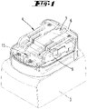
- Fig. 1
- eine Draufsicht auf einen Adapter mit einem daran unterseitig angekoppelten Akkumulator;
- Fig. 2
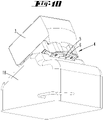
- eine mögliche Verbindung eines Geräteschaftes mit einem Adapter und daran befindlichem Akkumulator;
- Fig. 3
- der zusammengesetzte Geräteschaft mit Adapter und Akkumulator;
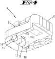
- Fig. 4
- eine perspektivische Ansicht von unten eines Adapters;
- Fig. 5
- eine Explosionsdarstellung eines Adapters;
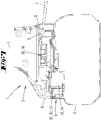
- Fig. 6
- einen Querschnitt durch den Gerätefuß gemäß
Fig. 3 im Bereich des Adapters; - Fig. 7
- eine Verdeutlichung der möglichen Aufhebung der Rastverbindung zwischen dem Adapter und dem Geräteschaft (keine Ausführung gemäß der Erfindung);
- Fig. 8
- einen Querschnitt gemäß
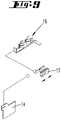
Fig. 6 , jedoch 90° gedreht bezüglich einer Geräteschaft-Längsachse; - Fig. 9
- eine schematische Darstellung einer in dem Adapter ausgeführten elektrischen Schaltung zur Leistungsunterbrechung;
- Fig. 10
- eine Kombination eines Adapters mit einem Akkumulator aufgesetzt auf ein Ladegerät;
- Fig. 11
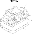
- eine Kombination eines Akkumulators zweiter Art mit einem angepassten Adapter;
- Fig. 12/ Fig. 13
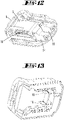
- einen Akkumulator zweiter Art, hinsichtlich seines zweiteiligen Aufbaus in Explosionsdarstellung; und
- Fig. 14
- eine Seitenansicht eines Geräteschaftes angekoppelt mit einem Adapter und Akkumulator gemäß
Fig. 11 . - Dargestellt und beschrieben ist, zunächst mit Bezug zu den
Fig. 1 bis 3 , ein hier nur teilweise dargestelltes Werkzeug 1, das einen Geräteschaft 2 aufweist, mit welchem ein Akkumulator 3 vermittels eines Adapters 4 verbindbar ist. Der Adapter 4 kann an die Konfiguration eines ersten Akkumulators 3 angepasst sein. Der Geräteschaft 2 kann an die Konfiguration eines zweiten Akkumulators 3 angepasst sein, der dann ohne den Adapter 4 unmittelbar mit dem Geräteschaft 2 verbunden werden kann. - Der Adapter 4 ist mit dem Geräteschaft 2 rastverbindbar, wie sich dies in weiterer Einzelheit aus den
Figuren 6 und7 ergibt. Zur Rastverbindbarkeit zwischen dem Geräteschaft 2 und dem Adapter 4 ist bevorzugt in dem Adapter 4 ein Löseteil, beim Ausführungsbeispiel ein gegen Federkraft - hier nach unten - ausweichbares Rastteil 5 vorgesehen. Das Rastteil 5 ist gegenüber einer Außenwandung 6 des Adapters 4 nach innen versetzt. Es muss also in das Innere des Adapters 4 eingegriffen werden, um das Rastteil 5 zu betätigen. Bei der Ausführungsform derFigur 6 ist die Außenwandung 6 durchgehend ausgebildet. Der hier einmal verrastend eingesetzte Adapter 4 kann nicht ohne Zerstörung der Außenwand 6 wieder gelöst werden. Die Außenwand 6 weist auch eine Türe oder Rastöffnung auf. - Wie sich aus
Figur 7 (keine Ausführung gemäß der Erfindung) ergibt, kann im Falle, dass die Außenwand 6 nicht durchgehend gebildet ist, die mögliche Betätigung des Rastteils 5 auch mittels eines Werkzeugs, wie eines hier nur teilweise dargestellten Schraubendrehers 7 möglich sein. - Bei dem hier dargestellten Adapter 4 handelt es sich um einen Einschubadapter. Dieser wird im Wesentlichen rechtwinklig zu einer Längsachse L des Geräteschaftes 2 mit dem Geräteschaft 2 schiebeverbunden. Eine vordere Abdeckwandung 8 des Geräteschaftes stellt dabei einen Schiebeanschlag dar. Zudem sind innenseitig des Geräteschaftes bevorzugt Vorsprünge vorgesehen, die mit Ausnehmungen 9 des Adapters zusammenwirken, so dass sich ein schienenartiges Zusammenfahren ergibt. Das Rastteil 5 ist damit das einzige bewegliche Teil, das zur Verankerung des Adapters 4 an dem Geräteschaft 2 erforderlich ist. Alternativ ist auch eine Ausgestaltung in Form eines nicht dargestellten Turm-Adapters möglich. Dieser wird in Längsrichtung des Geräteschaftes 2, üblicherweise durch Einschieben in einen an dem Geräteschaft ausgebildeten Aufnahmeraum, mit dem Gerät verbunden.
- Wie insbesondere aus
Figur 5 ersichtlich ist, die eine Explosionsdarstellung des Adapters wiedergibt, sind im Inneren des Adapters 4 Elektrokontakte 10 bis 14 angeordnet, welche nach unten vorragend, in entsprechenden Kontakten des Akkumulators im zusammengesteckten Zustand sind. Die elektrischen Ströme werden durchgeleitet zur Oberseite des Adapters 4, wo entsprechende Kontaktelemente 15, 16 angeordnet sind. Hierbei ist nicht nur eine Durchleitung von Plus und Minus möglich, sondern auch eine Durchleitung von Werten betreffend die Temperatur und/oder den Ladezustand und/oder weitere Daten, die in dem Akkumulator abgefragt werden. Herkömmliche Akkumulatoren stellen derartige Werte an entsprechenden Kontakten zur Verfügung. - Im Weiteren kann vorgesehen sein, dass innerhalb des Adapters 4, wie aus der in
Figur 9 wiedergegebenen elektrischen Schaltung ersichtlich, eine Unterbrechung einer Leistungsversorgung möglich ist, dies über einen Schalter 17. Der Schalter 17 kann entweder selbsttätig betätigbar sein, etwa indem eine gemessene Temperatur oder ein sonstiges gemessenes Datum innerhalb des Adapters und/oder durch Durchleitung der Werte zunächst in das Gerät, in dem Gerät, in einem Mikroprozessor oder dergleichen, mit zulässigen Daten verglichen wird und in Abhängigkeit hiervon die Leistungsunterbrechung vorgenommen wird oder nicht. Der Schalter kann auch von Hand betätigbar vorgesehen sein. - Weiter kann vorgesehen sein, was im Einzelnen nicht dargestellt ist, dass der Adapter zum Abgeben eines Signals, beispielsweise eines Licht- und/oder Tonsignals, ausgebildet ist.
- Auch kann der Akkumulator 3 zusammen mit einem steckverbundenen Adapter 4, wie etwa in den
Figuren 9 und10 dargestellt, aufladbar sein. Hierbei ist ein Ladegerät 18 vermittels des Adapters 4 mit dem Akkumulator 3 zum Aufladen verbunden. Dies ist insbesondere deshalb möglich, weil der Adapter 4 bei dieser Ausführungsform mehr elektrische Durchleitungskontakte aufweist als nur die zur elektrischen Leistungsversorgung erforderlichen zwei elektrischen Kontakte, nämlich weiter auch elektrische Durchleitungskontakte betreffend die Temperatur des Akkumulators und/oder den Ladezustand einer Ladezelle des Akkumulators etc. - Die Durchleitung von Daten kann auch allein oder ergänzend, auf optischem, magnetischem, funktechnischem oder mechanischem Wege erfolgen.
-
- 1
- Werkzeug
- 2
- Geräteschaft
- 3
- Akkumulator
- 4
- Adapter
- 5
- Rastteil
- 6
- Außenwandung
- 7
- Schraubendreher
- 8
- Abdeckwandung
- 9
- Ausnehmung
- 10
- Elektrokontakt
- 11
- Elektrokontakt
- 12
- Elektrokontakt
- 13
- Elektrokontakt
- 14
- Elektrokontakt
- 15
- Kontaktelement
- 16
- Kontaktelement
- 17
- Schalter
- 18
- Ladegerät
- L
- Längsachse
Claims (11)
- Hydraulisch oder elektromotorisch betriebenes Werkzeug (1), beispielsweise ein Verpressgerät, mit einem Geräteschaft (2), der zumindest einen ersten und einen zweiten Elektrokontakt aufweist und mit einem mit dem Geräteschaft (2) rastverbindbaren Akkumulator (3), wobei zwischen dem Geräteschaft (2) und dem Akkumulator (3) ein an dem Geräteschaft (2) mittels einer Rastverbindung zu dem Geräteschaft (2) sicherbarer Adapter (4) vorgesehen ist, wobei der Adapter (4) zu dem Akkumulator (3) sicherbar ist, dadurch gekennzeichnet, dass die Rastverbindung des Adapters (4) zu dem Geräteschaft (2) ohne Zerstörung eines Teils des Adapters (4) nicht aufhebbar ist.
- Werkzeug nach Anspruch 1, dadurch gekennzeichnet, dass der Adapter (4) an die Konfiguration eines ersten Akkumulators (3) angepasst ist und dass der Geräteschaft (2) an die Konfiguration eines zweiten Akkumulators (3) angepasst ist.
- Werkzeug nach einem der vorhergehenden Ansprüche, dadurch gekennzeichnet, dass der Adapter (4) jedenfalls auf seiner dem Akkumulator (3) zugewandten Seite Kontakte zur Erfassung und gegebenenfalls Durchleitung von Werten betreffend die Temperatur und/oder den Ladezustand, gegebenenfalls auch im Hinblick auf einzelne Zellen des Akkumulators (3), aufweist.
- Werkzeug nach einem der vorhergehenden Ansprüche, dadurch gekennzeichnet, dass der Adapter (4) zur Unterbrechung einer Leistungsversorgung des Werkzeugs ausgebildet ist.
- Werkzeug nach einem der vorhergehenden Ansprüche, dadurch gekennzeichnet, dass in dem Akkumulator (3) ein Leistungsschalter (17) angeordnet ist.
- Werkzeug nach Anspruch 5, dadurch gekennzeichnet, dass der Leistungsschalter (17) in Abhängigkeit eines Zustandsdatums des Akkumulators (3) selbsttätig schaltet.
- Werkzeug nach einem der Ansprüche 5 oder 6, dadurch gekennzeichnet, dass der Leistungsschalter (17) in Abhängigkeit einer Temperatur und/oder des Ladezustandes des Akkumulators (3) schaltet.
- Werkzeug nach einem der vorhergehenden Ansprüche, dadurch gekennzeichnet, dass der Akkumulator (3) mit steckverbundenem Adapter (4) aufladbar ist, wobei der Akkumulator (3) mit dem Ladegerät (18) vermittels des Adapters (4) verbunden ist.
- Werkzeug nach einem der vorhergehenden Ansprüche, dadurch gekennzeichnet, dass der Adapter (4) zum Abgeben eines Signals, beispielsweise eines Licht- und/oder Tonsignals, ausgebildet ist.
- Verfahren zum Betreiben eines hydraulischen oder elektromotorischen Werkzeuges (1), beispielswiese eines Verpressgerätes, mit einem Geräteschaft (2), der zumindest einen ersten und einen zweiten Elektrokontakt aufweist und mit einem mit dem Geräteschaft (2) rastverbindbaren Ackumulator (3), wobei zwischen dem Geräteschaft (2) und dem Akkumulator (3) ein Adapter (4) vorgesehen wird, der mit dem Geräteschaft (2) mittels einer Rastverbindung gesichert wird, wobei der Adapter (4) mit dem Akkumulator (3) gesichert wird, dadurch gekennzeichnet, dass die Rastverbindung nicht ohne Zerstörung eines Teils des Adapters (4) aufgehoben wird.
- Verfahren nach Anspruch 10, dadurch gekennzeichnet, dass der Adapter die Merkmale eines der Ansprüche 2 bis 8 aufweist.
Applications Claiming Priority (2)
| Application Number | Priority Date | Filing Date | Title |
|---|---|---|---|
| DE102012104538A DE102012104538A1 (de) | 2012-05-25 | 2012-05-25 | Werkzeug |
| PCT/EP2013/059912 WO2013174675A1 (de) | 2012-05-25 | 2013-05-14 | Werkzeug |
Publications (2)
| Publication Number | Publication Date |
|---|---|
| EP2855101A1 EP2855101A1 (de) | 2015-04-08 |
| EP2855101B1 true EP2855101B1 (de) | 2022-06-22 |
Family
ID=48430792
Family Applications (1)
| Application Number | Title | Priority Date | Filing Date |
|---|---|---|---|
| EP13722441.6A Active EP2855101B1 (de) | 2012-05-25 | 2013-05-14 | Werkzeug |
Country Status (4)
| Country | Link |
|---|---|
| US (2) | US20150165614A1 (de) |
| EP (1) | EP2855101B1 (de) |
| DE (1) | DE102012104538A1 (de) |
| WO (1) | WO2013174675A1 (de) |
Families Citing this family (8)
| Publication number | Priority date | Publication date | Assignee | Title |
|---|---|---|---|---|
| DE102012104538A1 (de) * | 2012-05-25 | 2013-11-28 | Gustav Klauke Gmbh | Werkzeug |
| JP6345523B2 (ja) * | 2014-07-23 | 2018-06-20 | 株式会社やまびこ | バッテリ駆動式作業機 |
| EP3025825A1 (de) | 2014-11-27 | 2016-06-01 | HILTI Aktiengesellschaft | Selbstsperrende Verriegelung einer Adaptervorrichtung |
| DE102014225998A1 (de) | 2014-12-16 | 2016-06-16 | Robert Bosch Gmbh | Handwerkzeugmaschine |
| DE102015110308B4 (de) * | 2015-03-09 | 2022-01-20 | Metabowerke Gmbh | Akkupack für ein Elektrohandwerkzeuggerät |
| DE102017129619A1 (de) * | 2017-12-12 | 2019-06-13 | Metabowerke Gmbh | Vorrichtung zur Verriegelung eines Akkupacks |
| DE102021212585A1 (de) * | 2021-11-09 | 2023-05-11 | Robert Bosch Gesellschaft mit beschränkter Haftung | Handwerkzeugmaschine mit einer Akkupackschnittstelle |
| EP4342639A1 (de) * | 2022-09-23 | 2024-03-27 | C. & E. Fein GmbH | Lagervorrichtung für ein akkumulatormodul an einem handwerkzeug |
Family Cites Families (80)
| Publication number | Priority date | Publication date | Assignee | Title |
|---|---|---|---|---|
| US311910A (en) * | 1885-02-10 | Box-fastener | ||
| US949409A (en) * | 1909-03-18 | 1910-02-15 | Sanford N Badger | Lock. |
| US3855851A (en) * | 1971-10-26 | 1974-12-24 | W Paul | Tamper-proof time interval recording system |
| US3978186A (en) * | 1974-11-25 | 1976-08-31 | Beatrice Foods Co. | Method for making a partitioned container |
| US3999110A (en) * | 1975-02-06 | 1976-12-21 | The Black And Decker Manufacturing Company | Battery pack and latch |
| US4160857A (en) * | 1978-02-16 | 1979-07-10 | Codman & Shurtleff, Inc. | Canister and removable battery pack unit therefor |
| GB2044515B (en) * | 1979-03-07 | 1983-04-20 | Chloride Group Ltd | Electric batteries |
| US4220363A (en) * | 1979-04-30 | 1980-09-02 | Superior Switchboard & Devices Division of The Union Metal Manufacturing Co. | Latch for meter box |
| US4391883A (en) * | 1981-09-28 | 1983-07-05 | Motorola, Inc. | Housing arrangement with breakaway battery access door |
| US4733337A (en) * | 1986-08-15 | 1988-03-22 | Lite Tek International Corp. | Miniature flashlight |
| DE10216213A1 (de) | 2002-04-10 | 2003-10-23 | Klauke Gmbh Gustav | Elektrohydraulisches Verpressgerät und Verfahren zum Betreiben desselben |
| DE3742268A1 (de) * | 1987-12-12 | 1989-06-22 | Licentia Gmbh | Elektrowerkzeug mit einer einrichtung zur aufnahme und halterung von batterie-packen im und/oder am werkzeuggehaeuse |
| US4871629A (en) * | 1988-02-04 | 1989-10-03 | Black & Decker Inc. | Latching arrangement for battery packs |
| US5271536A (en) * | 1992-02-07 | 1993-12-21 | Polytop Corporation | Flexible holder for "living" hinge joining lid to closure body of dispensing closure |
| US5213913A (en) * | 1992-02-21 | 1993-05-25 | Snap-On Tools Corporation | Latching arrangement for battery pack |
| US5318356A (en) * | 1992-09-22 | 1994-06-07 | Shelton J Calvin | Charger/shelter apparatus for electric shaver |
| US5553675A (en) * | 1994-06-10 | 1996-09-10 | Minnesota Mining And Manufacturing Company | Orthopedic surgical device |
| US5725304A (en) * | 1995-12-13 | 1998-03-10 | Makita Corporation | Battery concrete vibrator |
| ATE215273T1 (de) | 1997-10-15 | 2002-04-15 | Klauke Gmbh Gustav | Hydraulisches pressgerät |
| US6187471B1 (en) * | 1998-07-14 | 2001-02-13 | Zentek Corporation | Bimodal battery |
| US6168881B1 (en) * | 1998-08-14 | 2001-01-02 | S-B Power Tool Company | Latch mechanism for a battery operated power tool |
| US6536536B1 (en) * | 1999-04-29 | 2003-03-25 | Stephen F. Gass | Power tools |
| US6308378B1 (en) * | 1999-06-01 | 2001-10-30 | Porter-Cable Corporation | Frictional gripping arrangement for a power tool handle |
| DE19926481B4 (de) | 1999-06-10 | 2013-09-12 | Gustav Klauke Gmbh | Hydraulisches Arbeitsgerät |
| US6257351B1 (en) * | 1999-06-29 | 2001-07-10 | Microaire Surgical Instruments, Inc. | Powered surgical instrument having locking systems and a clutch mechanism |
| US6204632B1 (en) * | 1999-09-08 | 2001-03-20 | Selfcharge | Apparatus for charging multiple batteries |
| US6104162A (en) * | 1999-09-11 | 2000-08-15 | Sainsbury; Simon R. | Method and apparatus for multi-power source for power tools |
| US6286609B1 (en) * | 1999-12-10 | 2001-09-11 | Black & Decker Inc. | AC/DC chopper for power tool |
| JP2001300867A (ja) * | 2000-04-21 | 2001-10-30 | Makita Corp | 電動工具用アダプタ |
| US6350040B1 (en) * | 2000-05-05 | 2002-02-26 | Pelican Products, Inc. | Flashlight charger and rechargeable battery |
| US6525511B2 (en) | 2000-08-11 | 2003-02-25 | Milwaukee Electric Tool Corporation | Adapter for a power tool battery |
| US20020125857A1 (en) * | 2001-03-09 | 2002-09-12 | Thomas Mastaler | Battery adapter for a cordless power tool system and related method |
| US7501198B2 (en) * | 2002-02-07 | 2009-03-10 | Linvatec Corporation | Sterile transfer battery container |
| DE10242738A1 (de) * | 2002-09-13 | 2005-01-20 | Robert Bosch Gmbh | Handwekzeugmaschine, insbesondere Winkelschleifmaschine |
| US7589500B2 (en) * | 2002-11-22 | 2009-09-15 | Milwaukee Electric Tool Corporation | Method and system for battery protection |
| US6729415B1 (en) * | 2003-04-18 | 2004-05-04 | Techway Industrial Co., Ltd. | Portable electric tool with bi-directionally mountable battery holder |
| DE10318947A1 (de) * | 2003-04-26 | 2004-11-18 | Robert Bosch Gmbh | Elektrische Handwerkzeugmaschine mit Akkupack |
| US7007986B2 (en) * | 2003-05-30 | 2006-03-07 | Kearney-National Inc. | Access cover fastening device |
| PL1628692T3 (pl) * | 2003-06-02 | 2012-04-30 | Reckitt Benckiser Uk Ltd | Urządzenie do emitowania środka chemicznego |
| US20050058890A1 (en) * | 2003-09-15 | 2005-03-17 | Kenneth Brazell | Removable battery pack for a portable electric power tool |
| CN2659647Y (zh) * | 2003-10-22 | 2004-12-01 | 李国昌 | 一种可分体电动工具 |
| US6883621B1 (en) * | 2004-01-05 | 2005-04-26 | Jack Lin | Power supply structure of electromotive tool |
| US20050153596A1 (en) * | 2004-01-13 | 2005-07-14 | Vanwambeke Weston | Power tool battery connector |
| US7320843B2 (en) * | 2004-02-27 | 2008-01-22 | Great Stuff, Inc. | Battery assembly with shielded terminals |
| US7160132B2 (en) * | 2004-03-31 | 2007-01-09 | Black & Decker Inc. | Battery pack—cordless power device interface system |
| US7176656B2 (en) * | 2004-06-22 | 2007-02-13 | Campbell Hausfeld/Scott Fetzer Company | Tool with battery pack |
| US20060222931A1 (en) * | 2005-03-29 | 2006-10-05 | Jack Lin | Connection of battery pack and cordless hand tools |
| US7969116B2 (en) * | 2005-04-04 | 2011-06-28 | Hitachi Koki Co., Ltd. | Power pack and cordless power tool having the same |
| US7186117B2 (en) * | 2005-04-11 | 2007-03-06 | Tranmax Machinery Co., Ltd. | Connection mechanism for battery pack and power tools |
| DE102005050781B4 (de) * | 2005-10-24 | 2018-04-19 | Robert Bosch Gmbh | Vorrichtung zur Verriegelung eines Elektrowerkzeugs und eines in einer Führung des Elektrowerkzeugs verschiebbaren Akkupacks |
| SE531000C2 (sv) * | 2005-11-17 | 2008-11-11 | Atlas Copco Tools Ab | System för bibringande av de olika driftsegenskaper till ett batteridrivet skruvåtdragningsverktyg |
| CN100999074A (zh) | 2005-12-13 | 2007-07-18 | 密尔沃基电动工具公司 | 用于电动工具电池的适配器 |
| US20070210744A1 (en) * | 2006-03-10 | 2007-09-13 | Watson James B | Adapter for a power tool battery |
| US20070227310A1 (en) * | 2006-03-31 | 2007-10-04 | Heiko Roehm | Hand power tool |
| US7629766B2 (en) * | 2006-07-17 | 2009-12-08 | Bbs Licensing, Inc. | Adapter system for battery-powered tools |
| US8228029B2 (en) * | 2007-02-23 | 2012-07-24 | Milwaukee Electric Tool Corporation | Power tool, battery pack, and method of operating the same |
| JP4104648B1 (ja) * | 2007-09-13 | 2008-06-18 | 和征 榊原 | 電池パック |
| JP5151363B2 (ja) * | 2007-09-28 | 2013-02-27 | 三菱自動車工業株式会社 | 電気自動車用バッテリケース |
| DE102007057453A1 (de) * | 2007-11-29 | 2009-06-04 | Robert Bosch Gmbh | Handwerkzeugmaschine |
| US7999507B2 (en) * | 2007-12-10 | 2011-08-16 | Illinois Tool Works Inc. | Power tool having mating battery terminals |
| US20090246608A1 (en) * | 2008-03-26 | 2009-10-01 | Simon Wu | Rechargeable Electric Tool with a Battery Pack Detaching Device |
| FR2929544B1 (fr) * | 2008-04-02 | 2010-09-03 | Facom | Appareil electrique portatif autonome a verrouillage du bloc d'alimentation electrique. |
| DE102008040061A1 (de) * | 2008-07-02 | 2010-01-07 | Robert Bosch Gmbh | Elektrowerkzeugmaschine |
| DE102009012175A1 (de) * | 2009-02-27 | 2010-09-02 | Andreas Stihl Ag & Co. Kg | Elektroarbeitsgerät mit einem Akkupack |
| US20100136402A1 (en) * | 2009-04-22 | 2010-06-03 | Tesla Motors, Inc. | Sealed battery enclosure |
| EP2329921B1 (de) * | 2009-12-07 | 2016-03-16 | Black & Decker Inc. | Antidiebstahlsystem |
| JP5432761B2 (ja) * | 2010-02-12 | 2014-03-05 | 株式会社マキタ | 複数のバッテリパックを電源とする電動工具 |
| DE102010002702A1 (de) * | 2010-03-09 | 2011-09-15 | Robert Bosch Gmbh | Elektrogerät, insbesondere Elektrohandwerkzeug |
| JP5554622B2 (ja) * | 2010-04-21 | 2014-07-23 | 株式会社マキタ | 電動工具用装置 |
| US8048552B1 (en) * | 2010-04-23 | 2011-11-01 | Psion Inc. | Battery module mount |
| JP2012043692A (ja) * | 2010-08-20 | 2012-03-01 | Makita Corp | 工具用バッテリ |
| JP5587801B2 (ja) * | 2010-09-13 | 2014-09-10 | 株式会社マキタ | 充電式電動工具 |
| DE102011113126B4 (de) * | 2011-09-14 | 2015-05-13 | Olaf Storz | Leistungseinheit und medizinisches Handgerät |
| US20130091905A1 (en) * | 2011-10-17 | 2013-04-18 | Display Technologies, Inc. | Anti-theft device including a strap and method of use |
| DE102012104538A1 (de) * | 2012-05-25 | 2013-11-28 | Gustav Klauke Gmbh | Werkzeug |
| EP2897195B1 (de) * | 2012-09-14 | 2016-03-09 | Nissan Motor Co., Ltd | Druckentlastungsstruktur für ein fahrzeugbatteriepack |
| US11211655B2 (en) * | 2015-03-31 | 2021-12-28 | Ford Global Technologies, Llc | Vehicle enclosure for preventing access to high voltage components |
| JP2019050150A (ja) * | 2017-09-11 | 2019-03-28 | 三菱自動車工業株式会社 | 蓋体の取付構造 |
| US11059155B2 (en) * | 2018-01-26 | 2021-07-13 | Milwaukee Electric Tool Corporation | Percussion tool |
| WO2020018844A1 (en) * | 2018-07-18 | 2020-01-23 | Nexkey, Inc. | Wireless electric lock core |
-
2012
- 2012-05-25 DE DE102012104538A patent/DE102012104538A1/de not_active Ceased
-
2013
- 2013-05-14 WO PCT/EP2013/059912 patent/WO2013174675A1/de not_active Ceased
- 2013-05-14 EP EP13722441.6A patent/EP2855101B1/de active Active
- 2013-05-14 US US14/403,373 patent/US20150165614A1/en not_active Abandoned
-
2018
- 2018-04-30 US US15/966,496 patent/US10654159B2/en active Active
Also Published As
| Publication number | Publication date |
|---|---|
| DE102012104538A1 (de) | 2013-11-28 |
| US20180243895A1 (en) | 2018-08-30 |
| US20150165614A1 (en) | 2015-06-18 |
| EP2855101A1 (de) | 2015-04-08 |
| US10654159B2 (en) | 2020-05-19 |
| WO2013174675A1 (de) | 2013-11-28 |
Similar Documents
| Publication | Publication Date | Title |
|---|---|---|
| EP2855101A1 (de) | Werkzeug | |
| EP2831957B1 (de) | Sicherungssystem für hochstromanwendungen | |
| DE4036374A1 (de) | Ladeeinrichtung fuer wiederaufladbare batterien | |
| WO2005039829A1 (de) | Akkuschrauber | |
| DE112018004505T5 (de) | Anschluss-Sperraktuatorvorrichtung für Fahrzeugeingangsanschluss | |
| DE102016209822A1 (de) | Akkupack für eine Handwerkzeugmaschine und/oder ein Ladegerät | |
| DE102011052078A1 (de) | Ladekupplung und Ladekupplungsanordnung für ein Kraftfahrzeug sowie Kraftfahrzeug | |
| EP4279326B1 (de) | Dockingstation, ladesystem, computerprogrammprodukt und verfahren | |
| EP2819207B1 (de) | Kombination aus Tragesystem, Batterie und anzutreibendem Gerät | |
| EP3571087B1 (de) | Batteriesystem für ein fahrzeug | |
| DE102010041317A1 (de) | Ladeeinrichtung für ein Elektrofahrzeug nebst Verfahren | |
| DE202009002787U1 (de) | Akkupack | |
| EP2323197A2 (de) | Batterie mit Haltevorrichtung | |
| DE202019100399U1 (de) | Lasttrennschaltervorrichtung und Schaltersicherungsvorrichtung mit Sicherung | |
| DE112014003362T5 (de) | Elektrogerät, einen Elektrostecker mit unverletzlichen Ablesemitteln umfassend, und elektrisches System mit einem solchen Gerät | |
| EP1927152A1 (de) | Akkupack und elektrohandwerkzeuggerät | |
| DE102011004215B4 (de) | Ladevorrichtung für Kraftfahrzeuge sowie Verfahren zum Laden eines Speichers für elektrische Ladung in einem Kraftfahrzeug | |
| DE102014002379A1 (de) | Elektrische Betätigungseinrichtung zum Öffnen und Schließen eines Kraftfahrzeuges | |
| EP3364493A1 (de) | Akkupack mit temperatursensor | |
| EP3365948A1 (de) | Steckdose mit identifikationsmittel | |
| EP2648287B1 (de) | Fahrzeugseitige Dose eines Ladesteckverbinders, insbesondere für Flurförderfahrzeuge | |
| DE102013009215A1 (de) | Steckvorrichtung, Aufnahmevorrichtung sowie Adaptervorrichtung zur Versorgung eines elektrisch antreibbaren Fortbewegungsmittels oder eines Hochstromverbrauchers | |
| DE102016012849A1 (de) | Batterie zum Anschließen an eine elektrische Anlage eines elektrisch antreibbaren Kraftfahrzeugs | |
| DE102012203511A1 (de) | Einschubrahmen für ein elektrisches Einschubschaltgerät sowie Einheit aus Einschubrahmen und elektrischem Einschubschaltgerät | |
| EP0411281B1 (de) | Elektrische Anschlussklemme |
Legal Events
| Date | Code | Title | Description |
|---|---|---|---|
| PUAI | Public reference made under article 153(3) epc to a published international application that has entered the european phase |
Free format text: ORIGINAL CODE: 0009012 |
|
| 17P | Request for examination filed |
Effective date: 20141210 |
|
| AK | Designated contracting states |
Kind code of ref document: A1 Designated state(s): AL AT BE BG CH CY CZ DE DK EE ES FI FR GB GR HR HU IE IS IT LI LT LU LV MC MK MT NL NO PL PT RO RS SE SI SK SM TR |
|
| AX | Request for extension of the european patent |
Extension state: BA ME |
|
| DAX | Request for extension of the european patent (deleted) | ||
| STAA | Information on the status of an ep patent application or granted ep patent |
Free format text: STATUS: EXAMINATION IS IN PROGRESS |
|
| 17Q | First examination report despatched |
Effective date: 20181009 |
|
| GRAP | Despatch of communication of intention to grant a patent |
Free format text: ORIGINAL CODE: EPIDOSNIGR1 |
|
| STAA | Information on the status of an ep patent application or granted ep patent |
Free format text: STATUS: GRANT OF PATENT IS INTENDED |
|
| INTG | Intention to grant announced |
Effective date: 20220107 |
|
| GRAS | Grant fee paid |
Free format text: ORIGINAL CODE: EPIDOSNIGR3 |
|
| GRAA | (expected) grant |
Free format text: ORIGINAL CODE: 0009210 |
|
| STAA | Information on the status of an ep patent application or granted ep patent |
Free format text: STATUS: THE PATENT HAS BEEN GRANTED |
|
| AK | Designated contracting states |
Kind code of ref document: B1 Designated state(s): AL AT BE BG CH CY CZ DE DK EE ES FI FR GB GR HR HU IE IS IT LI LT LU LV MC MK MT NL NO PL PT RO RS SE SI SK SM TR |
|
| REG | Reference to a national code |
Ref country code: GB Ref legal event code: FG4D Free format text: NOT ENGLISH |
|
| REG | Reference to a national code |
Ref country code: CH Ref legal event code: EP |
|
| REG | Reference to a national code |
Ref country code: DE Ref legal event code: R096 Ref document number: 502013016174 Country of ref document: DE |
|
| REG | Reference to a national code |
Ref country code: AT Ref legal event code: REF Ref document number: 1499475 Country of ref document: AT Kind code of ref document: T Effective date: 20220715 |
|
| REG | Reference to a national code |
Ref country code: IE Ref legal event code: FG4D Free format text: LANGUAGE OF EP DOCUMENT: GERMAN |
|
| REG | Reference to a national code |
Ref country code: LT Ref legal event code: MG9D |
|
| REG | Reference to a national code |
Ref country code: NL Ref legal event code: MP Effective date: 20220622 |
|
| PG25 | Lapsed in a contracting state [announced via postgrant information from national office to epo] |
Ref country code: SE Free format text: LAPSE BECAUSE OF FAILURE TO SUBMIT A TRANSLATION OF THE DESCRIPTION OR TO PAY THE FEE WITHIN THE PRESCRIBED TIME-LIMIT Effective date: 20220622 Ref country code: NO Free format text: LAPSE BECAUSE OF FAILURE TO SUBMIT A TRANSLATION OF THE DESCRIPTION OR TO PAY THE FEE WITHIN THE PRESCRIBED TIME-LIMIT Effective date: 20220922 Ref country code: LT Free format text: LAPSE BECAUSE OF FAILURE TO SUBMIT A TRANSLATION OF THE DESCRIPTION OR TO PAY THE FEE WITHIN THE PRESCRIBED TIME-LIMIT Effective date: 20220622 Ref country code: HR Free format text: LAPSE BECAUSE OF FAILURE TO SUBMIT A TRANSLATION OF THE DESCRIPTION OR TO PAY THE FEE WITHIN THE PRESCRIBED TIME-LIMIT Effective date: 20220622 Ref country code: GR Free format text: LAPSE BECAUSE OF FAILURE TO SUBMIT A TRANSLATION OF THE DESCRIPTION OR TO PAY THE FEE WITHIN THE PRESCRIBED TIME-LIMIT Effective date: 20220923 Ref country code: FI Free format text: LAPSE BECAUSE OF FAILURE TO SUBMIT A TRANSLATION OF THE DESCRIPTION OR TO PAY THE FEE WITHIN THE PRESCRIBED TIME-LIMIT Effective date: 20220622 Ref country code: BG Free format text: LAPSE BECAUSE OF FAILURE TO SUBMIT A TRANSLATION OF THE DESCRIPTION OR TO PAY THE FEE WITHIN THE PRESCRIBED TIME-LIMIT Effective date: 20220922 |
|
| PG25 | Lapsed in a contracting state [announced via postgrant information from national office to epo] |
Ref country code: RS Free format text: LAPSE BECAUSE OF FAILURE TO SUBMIT A TRANSLATION OF THE DESCRIPTION OR TO PAY THE FEE WITHIN THE PRESCRIBED TIME-LIMIT Effective date: 20220622 Ref country code: LV Free format text: LAPSE BECAUSE OF FAILURE TO SUBMIT A TRANSLATION OF THE DESCRIPTION OR TO PAY THE FEE WITHIN THE PRESCRIBED TIME-LIMIT Effective date: 20220622 |
|
| PG25 | Lapsed in a contracting state [announced via postgrant information from national office to epo] |
Ref country code: NL Free format text: LAPSE BECAUSE OF FAILURE TO SUBMIT A TRANSLATION OF THE DESCRIPTION OR TO PAY THE FEE WITHIN THE PRESCRIBED TIME-LIMIT Effective date: 20220622 |
|
| PG25 | Lapsed in a contracting state [announced via postgrant information from national office to epo] |
Ref country code: SM Free format text: LAPSE BECAUSE OF FAILURE TO SUBMIT A TRANSLATION OF THE DESCRIPTION OR TO PAY THE FEE WITHIN THE PRESCRIBED TIME-LIMIT Effective date: 20220622 Ref country code: SK Free format text: LAPSE BECAUSE OF FAILURE TO SUBMIT A TRANSLATION OF THE DESCRIPTION OR TO PAY THE FEE WITHIN THE PRESCRIBED TIME-LIMIT Effective date: 20220622 Ref country code: RO Free format text: LAPSE BECAUSE OF FAILURE TO SUBMIT A TRANSLATION OF THE DESCRIPTION OR TO PAY THE FEE WITHIN THE PRESCRIBED TIME-LIMIT Effective date: 20220622 Ref country code: PT Free format text: LAPSE BECAUSE OF FAILURE TO SUBMIT A TRANSLATION OF THE DESCRIPTION OR TO PAY THE FEE WITHIN THE PRESCRIBED TIME-LIMIT Effective date: 20221024 Ref country code: ES Free format text: LAPSE BECAUSE OF FAILURE TO SUBMIT A TRANSLATION OF THE DESCRIPTION OR TO PAY THE FEE WITHIN THE PRESCRIBED TIME-LIMIT Effective date: 20220622 Ref country code: EE Free format text: LAPSE BECAUSE OF FAILURE TO SUBMIT A TRANSLATION OF THE DESCRIPTION OR TO PAY THE FEE WITHIN THE PRESCRIBED TIME-LIMIT Effective date: 20220622 Ref country code: CZ Free format text: LAPSE BECAUSE OF FAILURE TO SUBMIT A TRANSLATION OF THE DESCRIPTION OR TO PAY THE FEE WITHIN THE PRESCRIBED TIME-LIMIT Effective date: 20220622 |
|
| PG25 | Lapsed in a contracting state [announced via postgrant information from national office to epo] |
Ref country code: PL Free format text: LAPSE BECAUSE OF FAILURE TO SUBMIT A TRANSLATION OF THE DESCRIPTION OR TO PAY THE FEE WITHIN THE PRESCRIBED TIME-LIMIT Effective date: 20220622 Ref country code: IS Free format text: LAPSE BECAUSE OF FAILURE TO SUBMIT A TRANSLATION OF THE DESCRIPTION OR TO PAY THE FEE WITHIN THE PRESCRIBED TIME-LIMIT Effective date: 20221022 |
|
| REG | Reference to a national code |
Ref country code: DE Ref legal event code: R097 Ref document number: 502013016174 Country of ref document: DE |
|
| PG25 | Lapsed in a contracting state [announced via postgrant information from national office to epo] |
Ref country code: AL Free format text: LAPSE BECAUSE OF FAILURE TO SUBMIT A TRANSLATION OF THE DESCRIPTION OR TO PAY THE FEE WITHIN THE PRESCRIBED TIME-LIMIT Effective date: 20220622 |
|
| PG25 | Lapsed in a contracting state [announced via postgrant information from national office to epo] |
Ref country code: DK Free format text: LAPSE BECAUSE OF FAILURE TO SUBMIT A TRANSLATION OF THE DESCRIPTION OR TO PAY THE FEE WITHIN THE PRESCRIBED TIME-LIMIT Effective date: 20220622 |
|
| PLBE | No opposition filed within time limit |
Free format text: ORIGINAL CODE: 0009261 |
|
| STAA | Information on the status of an ep patent application or granted ep patent |
Free format text: STATUS: NO OPPOSITION FILED WITHIN TIME LIMIT |
|
| 26N | No opposition filed |
Effective date: 20230323 |
|
| P01 | Opt-out of the competence of the unified patent court (upc) registered |
Effective date: 20230528 |
|
| PGFP | Annual fee paid to national office [announced via postgrant information from national office to epo] |
Ref country code: FR Payment date: 20230516 Year of fee payment: 11 |
|
| PG25 | Lapsed in a contracting state [announced via postgrant information from national office to epo] |
Ref country code: SI Free format text: LAPSE BECAUSE OF FAILURE TO SUBMIT A TRANSLATION OF THE DESCRIPTION OR TO PAY THE FEE WITHIN THE PRESCRIBED TIME-LIMIT Effective date: 20220622 |
|
| PGFP | Annual fee paid to national office [announced via postgrant information from national office to epo] |
Ref country code: GB Payment date: 20230517 Year of fee payment: 11 |
|
| REG | Reference to a national code |
Ref country code: CH Ref legal event code: PL |
|
| PG25 | Lapsed in a contracting state [announced via postgrant information from national office to epo] |
Ref country code: MC Free format text: LAPSE BECAUSE OF FAILURE TO SUBMIT A TRANSLATION OF THE DESCRIPTION OR TO PAY THE FEE WITHIN THE PRESCRIBED TIME-LIMIT Effective date: 20220622 |
|
| REG | Reference to a national code |
Ref country code: BE Ref legal event code: MM Effective date: 20230531 |
|
| PG25 | Lapsed in a contracting state [announced via postgrant information from national office to epo] |
Ref country code: MC Free format text: LAPSE BECAUSE OF FAILURE TO SUBMIT A TRANSLATION OF THE DESCRIPTION OR TO PAY THE FEE WITHIN THE PRESCRIBED TIME-LIMIT Effective date: 20220622 Ref country code: LU Free format text: LAPSE BECAUSE OF NON-PAYMENT OF DUE FEES Effective date: 20230514 Ref country code: LI Free format text: LAPSE BECAUSE OF NON-PAYMENT OF DUE FEES Effective date: 20230531 Ref country code: CH Free format text: LAPSE BECAUSE OF NON-PAYMENT OF DUE FEES Effective date: 20230531 |
|
| REG | Reference to a national code |
Ref country code: IE Ref legal event code: MM4A |
|
| PG25 | Lapsed in a contracting state [announced via postgrant information from national office to epo] |
Ref country code: IE Free format text: LAPSE BECAUSE OF NON-PAYMENT OF DUE FEES Effective date: 20230514 |
|
| PG25 | Lapsed in a contracting state [announced via postgrant information from national office to epo] |
Ref country code: IE Free format text: LAPSE BECAUSE OF NON-PAYMENT OF DUE FEES Effective date: 20230514 |
|
| PG25 | Lapsed in a contracting state [announced via postgrant information from national office to epo] |
Ref country code: BE Free format text: LAPSE BECAUSE OF NON-PAYMENT OF DUE FEES Effective date: 20230531 |
|
| REG | Reference to a national code |
Ref country code: AT Ref legal event code: MM01 Ref document number: 1499475 Country of ref document: AT Kind code of ref document: T Effective date: 20230514 |
|
| PG25 | Lapsed in a contracting state [announced via postgrant information from national office to epo] |
Ref country code: AT Free format text: LAPSE BECAUSE OF NON-PAYMENT OF DUE FEES Effective date: 20230514 |
|
| PG25 | Lapsed in a contracting state [announced via postgrant information from national office to epo] |
Ref country code: AT Free format text: LAPSE BECAUSE OF NON-PAYMENT OF DUE FEES Effective date: 20230514 |
|
| PG25 | Lapsed in a contracting state [announced via postgrant information from national office to epo] |
Ref country code: BG Free format text: LAPSE BECAUSE OF FAILURE TO SUBMIT A TRANSLATION OF THE DESCRIPTION OR TO PAY THE FEE WITHIN THE PRESCRIBED TIME-LIMIT Effective date: 20220622 |
|
| PG25 | Lapsed in a contracting state [announced via postgrant information from national office to epo] |
Ref country code: BG Free format text: LAPSE BECAUSE OF FAILURE TO SUBMIT A TRANSLATION OF THE DESCRIPTION OR TO PAY THE FEE WITHIN THE PRESCRIBED TIME-LIMIT Effective date: 20220622 |
|
| GBPC | Gb: european patent ceased through non-payment of renewal fee |
Effective date: 20240514 |
|
| PG25 | Lapsed in a contracting state [announced via postgrant information from national office to epo] |
Ref country code: FR Free format text: LAPSE BECAUSE OF NON-PAYMENT OF DUE FEES Effective date: 20240531 |
|
| PG25 | Lapsed in a contracting state [announced via postgrant information from national office to epo] |
Ref country code: GB Free format text: LAPSE BECAUSE OF NON-PAYMENT OF DUE FEES Effective date: 20240514 |
|
| PG25 | Lapsed in a contracting state [announced via postgrant information from national office to epo] |
Ref country code: CY Free format text: LAPSE BECAUSE OF FAILURE TO SUBMIT A TRANSLATION OF THE DESCRIPTION OR TO PAY THE FEE WITHIN THE PRESCRIBED TIME-LIMIT; INVALID AB INITIO Effective date: 20130514 |
|
| PG25 | Lapsed in a contracting state [announced via postgrant information from national office to epo] |
Ref country code: HU Free format text: LAPSE BECAUSE OF FAILURE TO SUBMIT A TRANSLATION OF THE DESCRIPTION OR TO PAY THE FEE WITHIN THE PRESCRIBED TIME-LIMIT; INVALID AB INITIO Effective date: 20130514 |
|
| PGFP | Annual fee paid to national office [announced via postgrant information from national office to epo] |
Ref country code: DE Payment date: 20250704 Year of fee payment: 13 |
|
| PG25 | Lapsed in a contracting state [announced via postgrant information from national office to epo] |
Ref country code: TR Free format text: LAPSE BECAUSE OF FAILURE TO SUBMIT A TRANSLATION OF THE DESCRIPTION OR TO PAY THE FEE WITHIN THE PRESCRIBED TIME-LIMIT Effective date: 20220622 |
|
| PGFP | Annual fee paid to national office [announced via postgrant information from national office to epo] |
Ref country code: IT Payment date: 20260526 Year of fee payment: 14 |