EP2855081B1 - Flux-cored tubular welding wire - Google Patents
Flux-cored tubular welding wire Download PDFInfo
- Publication number
- EP2855081B1 EP2855081B1 EP13728279.4A EP13728279A EP2855081B1 EP 2855081 B1 EP2855081 B1 EP 2855081B1 EP 13728279 A EP13728279 A EP 13728279A EP 2855081 B1 EP2855081 B1 EP 2855081B1
- Authority
- EP
- European Patent Office
- Prior art keywords
- welding wire
- approximately
- powder
- weight
- tubular welding
- Prior art date
- Legal status (The legal status is an assumption and is not a legal conclusion. Google has not performed a legal analysis and makes no representation as to the accuracy of the status listed.)
- Active
Links
Images

Classifications
-
- B—PERFORMING OPERATIONS; TRANSPORTING
- B23—MACHINE TOOLS; METAL-WORKING NOT OTHERWISE PROVIDED FOR
- B23K—SOLDERING OR UNSOLDERING; WELDING; CLADDING OR PLATING BY SOLDERING OR WELDING; CUTTING BY APPLYING HEAT LOCALLY, e.g. FLAME CUTTING; WORKING BY LASER BEAM
- B23K35/00—Rods, electrodes, materials, or media, for use in soldering, welding, or cutting
- B23K35/22—Rods, electrodes, materials, or media, for use in soldering, welding, or cutting characterised by the composition or nature of the material
- B23K35/24—Selection of soldering or welding materials proper
-
- B—PERFORMING OPERATIONS; TRANSPORTING
- B23—MACHINE TOOLS; METAL-WORKING NOT OTHERWISE PROVIDED FOR
- B23K—SOLDERING OR UNSOLDERING; WELDING; CLADDING OR PLATING BY SOLDERING OR WELDING; CUTTING BY APPLYING HEAT LOCALLY, e.g. FLAME CUTTING; WORKING BY LASER BEAM
- B23K35/00—Rods, electrodes, materials, or media, for use in soldering, welding, or cutting
- B23K35/40—Making wire or rods for soldering or welding
- B23K35/406—Filled tubular wire or rods
-
- B—PERFORMING OPERATIONS; TRANSPORTING
- B23—MACHINE TOOLS; METAL-WORKING NOT OTHERWISE PROVIDED FOR
- B23K—SOLDERING OR UNSOLDERING; WELDING; CLADDING OR PLATING BY SOLDERING OR WELDING; CUTTING BY APPLYING HEAT LOCALLY, e.g. FLAME CUTTING; WORKING BY LASER BEAM
- B23K35/00—Rods, electrodes, materials, or media, for use in soldering, welding, or cutting
- B23K35/02—Rods, electrodes, materials, or media, for use in soldering, welding, or cutting characterised by mechanical features, e.g. shape
- B23K35/0255—Rods, electrodes, materials, or media, for use in soldering, welding, or cutting characterised by mechanical features, e.g. shape for use in welding
- B23K35/0261—Rods, electrodes or wires
- B23K35/0266—Rods, electrodes or wires flux-cored
-
- B—PERFORMING OPERATIONS; TRANSPORTING
- B23—MACHINE TOOLS; METAL-WORKING NOT OTHERWISE PROVIDED FOR
- B23K—SOLDERING OR UNSOLDERING; WELDING; CLADDING OR PLATING BY SOLDERING OR WELDING; CUTTING BY APPLYING HEAT LOCALLY, e.g. FLAME CUTTING; WORKING BY LASER BEAM
- B23K35/00—Rods, electrodes, materials, or media, for use in soldering, welding, or cutting
- B23K35/22—Rods, electrodes, materials, or media, for use in soldering, welding, or cutting characterised by the composition or nature of the material
- B23K35/36—Selection of non-metallic compositions, e.g. coatings or fluxes; Selection of soldering or welding materials, conjoint with selection of non-metallic compositions, both selections being of interest
-
- B—PERFORMING OPERATIONS; TRANSPORTING
- B23—MACHINE TOOLS; METAL-WORKING NOT OTHERWISE PROVIDED FOR
- B23K—SOLDERING OR UNSOLDERING; WELDING; CLADDING OR PLATING BY SOLDERING OR WELDING; CUTTING BY APPLYING HEAT LOCALLY, e.g. FLAME CUTTING; WORKING BY LASER BEAM
- B23K35/00—Rods, electrodes, materials, or media, for use in soldering, welding, or cutting
- B23K35/22—Rods, electrodes, materials, or media, for use in soldering, welding, or cutting characterised by the composition or nature of the material
- B23K35/36—Selection of non-metallic compositions, e.g. coatings or fluxes; Selection of soldering or welding materials, conjoint with selection of non-metallic compositions, both selections being of interest
- B23K35/3601—Selection of non-metallic compositions, e.g. coatings or fluxes; Selection of soldering or welding materials, conjoint with selection of non-metallic compositions, both selections being of interest with inorganic compounds as principal constituents
- B23K35/3607—Silica or silicates
-
- B—PERFORMING OPERATIONS; TRANSPORTING
- B23—MACHINE TOOLS; METAL-WORKING NOT OTHERWISE PROVIDED FOR
- B23K—SOLDERING OR UNSOLDERING; WELDING; CLADDING OR PLATING BY SOLDERING OR WELDING; CUTTING BY APPLYING HEAT LOCALLY, e.g. FLAME CUTTING; WORKING BY LASER BEAM
- B23K35/00—Rods, electrodes, materials, or media, for use in soldering, welding, or cutting
- B23K35/22—Rods, electrodes, materials, or media, for use in soldering, welding, or cutting characterised by the composition or nature of the material
- B23K35/36—Selection of non-metallic compositions, e.g. coatings or fluxes; Selection of soldering or welding materials, conjoint with selection of non-metallic compositions, both selections being of interest
- B23K35/3601—Selection of non-metallic compositions, e.g. coatings or fluxes; Selection of soldering or welding materials, conjoint with selection of non-metallic compositions, both selections being of interest with inorganic compounds as principal constituents
- B23K35/3608—Titania or titanates
-
- B—PERFORMING OPERATIONS; TRANSPORTING
- B23—MACHINE TOOLS; METAL-WORKING NOT OTHERWISE PROVIDED FOR
- B23K—SOLDERING OR UNSOLDERING; WELDING; CLADDING OR PLATING BY SOLDERING OR WELDING; CUTTING BY APPLYING HEAT LOCALLY, e.g. FLAME CUTTING; WORKING BY LASER BEAM
- B23K35/00—Rods, electrodes, materials, or media, for use in soldering, welding, or cutting
- B23K35/22—Rods, electrodes, materials, or media, for use in soldering, welding, or cutting characterised by the composition or nature of the material
- B23K35/36—Selection of non-metallic compositions, e.g. coatings or fluxes; Selection of soldering or welding materials, conjoint with selection of non-metallic compositions, both selections being of interest
- B23K35/368—Selection of non-metallic compositions of core materials either alone or conjoint with selection of soldering or welding materials
-
- B—PERFORMING OPERATIONS; TRANSPORTING
- B23—MACHINE TOOLS; METAL-WORKING NOT OTHERWISE PROVIDED FOR
- B23K—SOLDERING OR UNSOLDERING; WELDING; CLADDING OR PLATING BY SOLDERING OR WELDING; CUTTING BY APPLYING HEAT LOCALLY, e.g. FLAME CUTTING; WORKING BY LASER BEAM
- B23K9/00—Arc welding or cutting
- B23K9/24—Features related to electrodes
-
- Y—GENERAL TAGGING OF NEW TECHNOLOGICAL DEVELOPMENTS; GENERAL TAGGING OF CROSS-SECTIONAL TECHNOLOGIES SPANNING OVER SEVERAL SECTIONS OF THE IPC; TECHNICAL SUBJECTS COVERED BY FORMER USPC CROSS-REFERENCE ART COLLECTIONS [XRACs] AND DIGESTS
- Y10—TECHNICAL SUBJECTS COVERED BY FORMER USPC
- Y10T—TECHNICAL SUBJECTS COVERED BY FORMER US CLASSIFICATION
- Y10T29/00—Metal working
- Y10T29/49—Method of mechanical manufacture
- Y10T29/49002—Electrical device making
- Y10T29/49117—Conductor or circuit manufacturing
Definitions
- the invention relates generally to welding and, more specifically, to a flux-cored tubular welding wire as defined in the preamble of claim 1, and to a method of manufacturing such a welding wire as defined in claim 7.
- a flux-cord tubular welding wire as defined in the preamble of claim 1 is known from CN 102 233 498 A . It is made of a steel belt and flux-cored powder, wherein the flux-cored powder comprises the following components in parts by weight: 4-10 parts of sintering powder, 0.1-0.7 part of Fe3O4, 0-1.0 part of TiO2, 0.1-0.5 part of Al, 0-0.4 part of Ti, 0.1-0.5 part of Si, 2.0-2.5 parts of Mn and 1.0-2.0 parts of Fe.
- EP 2 343 149 A1 discloses a flux-cored nickel-based alloy wire comprising a Mn content of 1,0 percent by mass or less.
- Welding is a process that has become ubiquitous in various industries for a variety of applications. For example, welding is often used in applications such as shipbuilding, offshore platform, construction, pipe mills, and so forth.
- Certain welding techniques e.g., Gas Metal Arc Welding (GMAW), Gas-shielded Flux Core Arc Welding (FCAW-G), Self-shielded Flux Core Arc Welding (FCAW-S), and Submerged Arc Welding (SAW)
- GMAW Gas Metal Arc Welding
- FCAW-G Gas-shielded Flux Core Arc Welding
- FCAW-S Self-shielded Flux Core Arc Welding
- SAW Submerged Arc Welding
- Welding wire may generally provide a supply of filler metal for the weld as well as provide a path for the current during the welding process.
- the present invention provides a flux-cored tubular welding wire as defined in claim 1.
- the present invention also provides a method of manufacturing a tubular welding wire as defined in claim 7.
- tubular welding electrode or tubular welding wire
- tubular welding wire may refer to any welding wire or electrode having a metal sheath and a granular or powdered core, such as metal-cored or flux-cored welding electrodes.
- tubular as used herein, may include various shapes of welding wire, including round, elliptical, square, polygonal, or any other suitable shape.
- Certain types of welding wire may include one or more components (e.g., flux, arc stabilizers, or other additives) that may generally alter the welding process and/or the properties of the resulting weld.
- rutile is a mineral, primarily composed of titanium dioxide (TiO 2 ), which may also include compounds of iron (Fe), niobium (Nb), tantalum (Ta), vanadium (V), and/or other impurities.
- rutile may be included in some types of welding wires, such as T-1 welding wires (e.g., AWS A5.20 EXXT-1, A5.29 EXXT1-YY, A5.36 EXXT-1, and EXXT1 -YY).
- T-1 welding wires e.g., AWS A5.20 EXXT-1, A5.29 EXXT1-YY, A5.36 EXXT-1, and EXXT1 -YY.
- certain types of welding wires may include a substantial quantity of manganese (Mn) (e.g., greater than 0.5% by weight) to function as a deoxidizer and/or an alloying metal for the resulting weld.
- this manganese content may react with oxygen near the welding environment to form oxides of manganese (e.g., manganese oxide (MnO) and/or manganese dioxide (MnO 2 )) that flow into the slag and/or transfer into the weld pool becoming incorporated into the weld metal to improve the mechanical properties of the resulting weld.
- manganese may form alloys with certain metals (e.g., steel) to provide improved strength, ductility, and toughness.
- the manganese may act as a deoxidizer reacting with oxygen (e.g., from the atmosphere) in order to block (e.g., limit or prevent) this oxygen from remaining in the weld deposit.
- manganese may react with and remove sulfur from the welding environment.
- manganese in a welding wire may help to control the weld puddle (e.g., by improving the wetting of the workpiece).
- a welding wire having low manganese content may volatilize only a small quantity of manganese during the welding operation.
- the present disclosure is directed toward systems and methods for welding wires having low manganese content that may be used to produce welds having a low manganese content (e.g., less than approximately 0.5%, less than approximately 0.4%, or less than 0.3% manganese by weight) while still providing suitable weld properties (e.g., tensile strength, ductility, toughness, and so forth).
- the presently disclosed welding wires generally maintain the weld quality (e.g., a weld having a reasonable level of inclusions, good strength, and/or good toughness) despite the low manganese content.
- the disclosed welding wires achieve the aforementioned welding properties and weld quality despite the low manganese content, at least in part, through the use of a purified, agglomerated titanium dioxide component.
- the granular core of presently disclosed tubular welding wire embodiments includes pigment-grade TiO 2 that has been agglomerated with binding and/or drying agents (e.g., sodium silicate, potassium silicate, lithium fluoride, and/or other binding or drying agents).
- binding and/or drying agents e.g., sodium silicate, potassium silicate, lithium fluoride, and/or other binding or drying agents.
- certain embodiments of the presently disclosed welding wire include high levels of deoxidizers (e.g., zirconium, aluminum, magnesium, silicon, and/or other suitable deoxidizers) to generally deter (e.g., block) oxygen incorporation into the weld metal.
- tubular welding wires enable the formation of weld deposits having relatively low manganese content (e.g., generally less than approximately 0.5% by weight) while still affording good weld properties (e.g., tensile strength, ductility, toughness, and so forth).
- FIG. 1 illustrates an example of a gas metal arc welding (GMAW) system 10 that utilizes tubular welding wire, in accordance with the present disclosure.
- GMAW gas metal arc welding
- the welding system 10 includes a welding power source 12, a welding wire feeder 14, a gas supply system 16, and a welding torch 18.
- the welding power source 12 generally supplies power to the welding system 10 and may be coupled to the welding wire feeder 14 via a cable bundle 20.
- the welding power source 12 may also be coupled to a workpiece 22 using a lead cable 24 having a clamp 26.
- the welding wire feeder 14 is coupled to the welding torch 18 via a cable bundle 28 in order to supply consumable, tubular welding wire (e.g., the welding electrode) and power to the welding torch 18 during operation of the welding system 10.
- the welding power source 12 may couple and directly supply power to the welding torch 18.
- the welding power source 12 may generally include power conversion circuitry that receives input power from an alternating current power source 30 (e.g., an AC power grid, an engine/generator set, or a combination thereof), conditions the input power, and provides DC or AC output power via the cable 20. As such, the welding power source 12 may power the welding wire feeder 14 that, in turn, powers the welding torch 18, in accordance with demands of the welding system 10.
- the lead cable 24 terminating in the clamp 26 couples the welding power source 12 to the workpiece 22 to close the circuit between the welding power source 12, the workpiece 22, and the welding torch 18.
- the welding power source 12 may include circuit elements (e.g., transformers, rectifiers, switches, and so forth) capable of converting the AC input power to a direct current electrode positive (DCEP) output, direct current electrode negative (DCEN) output, DC variable polarity, pulsed DC, or a variable balance (e.g., balanced or unbalanced) AC output, as dictated by the demands of the welding system 10.
- circuit elements e.g., transformers, rectifiers, switches, and so forth
- DCEP direct current electrode positive
- DCEN direct current electrode negative
- DC variable polarity e.g., pulsed DC
- a variable balance e.g., balanced or unbalanced
- the illustrated welding system 10 includes a gas supply system 16 that supplies a shielding gas or shielding gas mixtures from one or more shielding gas sources 17 to the welding torch 18.
- the gas supply system 16 is directly coupled to the welding torch 18 via a gas conduit 32.
- the gas supply system 16 may instead be coupled to the wire feeder 14, and the wire feeder 14 may regulate the flow of gas from the gas supply system 16 to the welding torch 18.
- the welding system 10 may not include the gas supply system 16.
- a shielding gas may refer to any gas or mixture of gases (e.g., inert or active gasses) that may be provided to the arc and/or weld pool in order to provide a particular local atmosphere (e.g., to shield the arc, improve arc stability, limit the formation of metal oxides, improve wetting of the metal surfaces, alter the chemistry of the weld deposit, and so forth).
- gases e.g., inert or active gasses
- the shielding gas flow may be a shielding gas or shielding gas mixture (e.g., argon (Ar), helium (He), carbon dioxide (CO 2 ), oxygen (O 2 ), nitrogen (N 2 ), hydrogen (H 2 ), similar suitable shielding gases, or any mixtures thereof).
- a shielding gas flow (e.g., delivered via the gas conduit 32) may include Ar, CO 2 , Ar/CO 2 mixtures (e.g., 75% Ar and 25% CO 2 , 90% Ar and 10% CO 2 , and so forth), Ar/CO 2 /O 2 mixtures, Ar/He mixtures, and so forth.
- certain shielding gases e.g., certain Ar/CO 2 mixtures, such as 90% Ar/ 10% CO 2
- certain shielding gases may reduce a total amount of welding fumes that may be generated during the welding operation.
- the illustrated welding torch 18 generally receives the tubular welding wire from the welding wire feeder 14, power from the welding power source 12, and a shielding gas flow from the gas supply system 16 in order to perform GMAW of the workpiece 22.
- the welding torch 18 may be brought near the workpiece 22 so that an arc 34 may be formed between the consumable welding electrode (i.e., the welding wire exiting a contact tip of the welding torch 18) and the workpiece 22.
- the composition of the tubular welding wire the chemical and mechanical properties of the resulting weld may be varied.
- the tubular welding wire includes a deoxidizing component to react with and remove undesired species (e.g., oxygen, metal oxides, or other undesired oxygen species) from the weld environment.
- the tubular welding wire further includes alloying components to contribute species (e.g., copper, molybdenum, silicon, carbon, or other suitable alloying components) to the weld pool, affecting the mechanical properties (e.g., strength and toughness) of the weld.
- species e.g., copper, molybdenum, silicon, carbon, or other suitable alloying components
- certain components of the tubular welding wire may also provide additional shielding atmosphere near the arc 34, affect the transfer properties of the arc 34, clean the surface of the workpiece 22, and so forth.
- FIG. 2 illustrates a tubular welding wire 50 having a metallic sheath 52 that encapsulates a granular or powdered core 54, which may also be referred to as filler.
- the metallic sheath 52 is manufactured from low-carbon steel or low-alloy steel.
- the metal sheath 52 provides 70% to 90% of the total weight of the tubular welding wire 50.
- the metallic sheath 52 may include additives or impurities (e.g., iron oxides, carbon, manganese, silicon, nickel, or similar compounds or elements) that may be selected to provide desired properties for the tubular welding wire 50 as well as the weld bead.
- certain embodiments of the tubular welding wire 50 may include a metallic sheath 52 having less than approximately 0.02% carbon by weight. In other embodiments, the metallic sheath 52 may include between approximately 0.02% and approximately 0.16% carbon by weight.
- the metallic sheath 52 of the tubular welding wire 50 may include relatively low manganese content.
- the amount of manganese that may be present in the metallic sheath 52 may be between approximately 0.01% and approximately 0.5% by weight (e.g., approximately 0.35% by weight or approximately 0.26% by weight), while the granular core 54 may be completely free or substantially free from manganese (e.g., including little or no metallic manganese and/or including little or no manganese compounds).
- the granular core 54 may include less than 0.1%, less than 0.05%, less than 0.04%, less than 0.03%, less than 0.02%, less than 0.01%, or approximately 0% (e.g., none or only trace impurity quantities) manganese by weight.
- a number of the presently disclosed tubular welding wire embodiments have a manganese content (e.g., manganese metal or alloys, or manganese compounds, or both) less than approximately 0.35% or less than approximately 0.4% by weight.
- the metallic sheath 52 may be completely free or substantially free (e.g., none or only trace impurity quantities) from manganese alloys, which may provide a tubular welding wire 50 that is completely free or substantially free of manganese metals and/or manganese compounds (e.g., manganese oxide).
- the granular core 54 of the illustrated tubular welding wire 50 generally is a compacted powder with a composition that, as discussed below, includes various components that each may serve at least one role as an alloying component, arc stabilizer, slag forming component, deoxidizer, and/or filler during the welding process. These components of the granular core 54 may be homogenously or non-homogenously (e.g., in clumps or clusters 56) disposed within the granular core 54.
- the granular core 54 provides between 10% and 30% of the total weight of the tubular welding wire 50.
- one or more components may be prepared and included in the granular core 54 as agglomerates (e.g., sintered and/or formed into frits).
- agglomerate or “frit,” as used herein, refers to a mixture of compounds that have been fired or heated in a calciner or oven such that the components of the mixture are in intimate contact with one another.
- the agglomerate or frit may have subtly or substantially different chemical and/or physical properties than the individual components of the mixture used to form the agglomerate.
- an agglomerate may generally be better suited for the weld environment (e.g., drier and/or better powder flow) than a non-agglomerated form of the same component.
- Tables 1, 2, and 3 are set forth below for various embodiments of the tubular welding wire 50. More specifically, Table 1 includes a non-limiting list of twelve example formulations (e.g., E1-E12) for the granular core 54 for the presently disclosed tubular welding wire 50. Table 2 includes computed chemical composition for each of the example formulations (E1-E12) of the granular core 54 based on the components set forth in Table 1. Furthermore, Table 3 includes chemical and mechanical analysis results for weld deposits formed using each of the welding wire embodiments set forth in Table 1. The welding wire embodiments E1-E12 may correspond to one or more AWS standards for welding wire.
- E1-E12 may correspond to one or more AWS standards for welding wire.
- E1 may correspond to AWS A5.20 E71T-1C
- E2 may correspond to AWS A5.20 E71T-1M
- E3 and E9 may correspond to AWS A5.29 E71T1-Ni1C (G);
- E4 and E10 may correspond to AWS A5.29 E71T1-Ni1M(G);
- E5 may correspond to AWS A5.29 E81T1-NiC;
- E6 may correspond to AWS A5.29 E81T1-Ni1M;
- E7 may correspond to AWS A5.29 E81T1-K2C (G);
- E8 may correspond to AWS A5.29 E81T1-K2M (G);
- E11 and E12 may correspond to AWS A5.20 E71T-G H8.
- the metallic sheath 52 may account for approximately 84% of the weight of the tubular welding wire 50, while the remaining approximately 16% of the weight of the tubular welding wire may be contributed by the granular core 54.
- the metallic sheath 52 may account for approximately 85% of the weight of the tubular welding wire 50, while the remaining approximately 15% may be contributed by the granular core.
- the metallic sheath 52 may include approximately 0.35% manganese, while embodiments E9-E12 may include a metallic sheath having approximately 0.26% manganese.
- each component in Table 1 may be listed as serving a particular purpose (e.g., as an alloying agent, arc stabilizer, slag former, deoxidizer, or filler), each component may actually serve more than one role in the welding process. That is, for example, TiO 2 provided to the weld environment by the agglomerated titanium dioxide and/or the rutile powder may actually provide stability to the arc 34 in addition to aiding in slag formation.
- certain deoxidizing components e.g., aluminum, magnesium, and/or zirconium
- certain deoxidizing components may also bind strongly to sulfur, which may come from the workpiece or from the welding consumable (e.g., as an impurity in the metallic sheath 52 or components of the granular core 54). As such, it should be appreciated that these components may be otherwise classified (e.g., as arc stabilizers, slag forming components, and/or deoxidizers) without altering the present invention.
- Table 1 Example formulations for the granular core 54 for embodiments E1-E12 of tubular welding wire 50. Values are in weight percent relative to the total weight of the granular core 54.
- Computed chemical composition for each of the example formulations (E1 - E12) of the granular core 54 based on the components set forth in Table 1. Values are in weight percent relative to the total weight of the granular core 54. Further, the list is not exhaustive and, as such, the amounts of each constituent may not sum up to unity.
- the granular core 54 of the tubular welding wire 50 includes between 4% and 18% alloying components by weight.
- the tubular welding wire 50 includes a granular core 54 having ferro-molybdenum metal powder, nickel powder, copper powder, and/or high-carbon (e.g., between approximately 3.2% and 3.9% carbon by weight) iron powder.
- the tubular welding wire 50 may include a granular core 54 having between approximately 0% and approximately 1.5% copper, between approximately 2% and approximately 12% nickel, between approximately 0% and approximately 1% molybdenum, and/or between approximately 0% and approximately 1% carbon by weight.
- these alloying components may otherwise contribute to the welding process (e.g., as arc stabilizers, slag formers, and/or deoxidizers), generally speaking, these alloying components are substantially incorporated (e.g., greater than 90% incorporated) into the weld metal to affect the properties (e.g., strength, ductility, corrosion resistance, and so forth) of the weld bead and the surrounding workpiece 22.
- the granular core 54 of the tubular welding wire 50 includes between 10% and 15% arc stabilizing components by weight.
- the tubular welding wire 50 includes a granular core 54 having iron oxides, potassium fluorosilicate, sodium titanate frit (e.g., made using either rutile or pigment-grade TiO 2 ), and/or lithium oxide agglomerate.
- certain embodiments of the tubular welding wire 50 may include a granular core 54 having between approximately 0% and 7.5% iron oxides, between approximately 0% and 2% potassium fluorosilicate, between approximately 0% and approximately 12% sodium titanate frit, and between 0% and 6% lithium oxide agglomerate by weight.
- these arc stabilizers may generally provide species to the arc that readily ionize, enabling a more consistent and/or controllable arc 34 to the surface of the workpiece 22.
- the presently disclosed sodium titanate frit may be a sintered mixture of sodium titanate and lithium fluoride and/or sodium silicate that may be better suited for the weld environment (e.g., drier and/or better powder flow) than non-agglomerated sodium titanate.
- the sodium titanate may be made from rutile and, accordingly, may have one or more of the aforementioned impurities that rutile may commonly include.
- the sodium titanate may instead be made from pigment grade TiO 2 , which may lack one or more of these impurities.
- a pigment-grade sodium titanate frit may include approximately 11.8% sodium oxide, approximately 5.7% silica, and approximately 82.5% pigment-grade TiO 2 .
- certain embodiments may include a lithium agglomerate that may be a sintered mixture of lithium oxide, iron oxides, sodium oxide, and silica, which may be better suited for the weld environment (e.g., drier and/or better powder flow) than a non-agglomerated mixture of these components.
- the lithium agglomerate may include approximately 18.7% lithium oxide, approximately 61.6% iron oxides, approximately 0.2% sodium oxide, and approximately 19.5% silica.
- the granular core 54 of the tubular welding wire 50 includes between 40% and 50% slag forming components by weight.
- the tubular welding wire 50 includes a granular core 54 having rutile powder, manganous oxide powder, and/or agglomerated titanium dioxide.
- certain embodiments of the presently disclosed welding wire 50 may have a granular core 54 that includes between approximately 3% and approximately 5% manganese oxide powder by weight.
- Other embodiments of the presently disclosed welding wire 50 may have a granular core 54 that includes substantially no (e.g., approximately 0%) manganese oxide powder by weight.
- a manganese content e.g., as a metal and/or as a component of a chemical compound
- the granular core 54 of the tubular welding wire 50 may include between approximately 45% and approximately 55% titanium dioxide by weight (e.g., from the rutile and/or agglomerated titanium dioxide sources). Accordingly, the tubular welding wire 50 includes between 6% and 8% pigment-grade TiO 2 by weight.
- the TiO 2 used to form the presently disclosed agglomerated titanium dioxide is a pigment-grade TiO 2 (e.g., greater than 95%, 99%, 99.9%, or 99.99% TiO 2 ) that may lack or have lower levels of one or more impurities typically found in rutile (e.g., iron, niobium, tantalum, vanadium, and/or other impurities). That is, pigment grade TiO 2 is generally both purified and milled, in contrast to lower purity TiO 2 , such as milled rutile.
- rutile e.g., iron, niobium, tantalum, vanadium, and/or other impurities
- this pigment-grade TiO 2 may be sintered with one or more drying and/or binding agents (e.g., lithium fluoride, and/or sodium silicate) to form the agglomerated titanium dioxide component of the granular core 54.
- drying and/or binding agents e.g., lithium fluoride, and/or sodium silicate
- an agglomerated titanium dioxide component may be formed by dry mixing purified TiO 2 powder and purified (e.g., precipitated grade) lithium fluoride for a period of time (e.g., 10 min).
- a concentrated aqueous solution of sodium silicate and a concentrated aqueous solution of potassium silicate may be slowly added to the dry mixture along with, in certain situations, a small quantity of water until a desired consistency is achieved (e.g., mixture begins to "ball").
- a desired consistency e.g., mixture begins to "ball”
- the wet mixture may be disposed in an oven (e.g., a direct fired kiln) and heated to approximately 1200 °F to approximately 1600 °F for approximately 15 to 25 minutes (or heated to similar temperatures in a pan for approximately 2 hours).
- the TiO 2 agglomerate may be made from approximately 81.3% purified TiO 2 , approximately 11% sodium silicate, approximately 6% potassium silicate, and approximately 1.7% lithium fluoride.
- the agglomerate may consist of pigment-grade TiO 2 , silica, potassium oxide, sodium oxide and lithium fluoride (e.g., approximately 90.7% TiO 2 , approximately 5.4% silica, approximately 1.2% sodium oxide, approximately 0.8% potassium oxide, and approximately 1.9% lithium fluoride).
- the granular core 54 of the tubular welding wire 50 includes between 10% and 15% deoxidizers by weight.
- the tubular welding wire 50 includes a granular core 54 having magnesium powder, aluminum-zirconium metal powder, ferro-zirconium-silicon powder, aluminum-magnesium metal powder, aluminum powder, ferro-silicon metal powder, and/or calcium silicon powder.
- certain embodiments of tubular welding wire 50 may have a granular core 54 that includes aluminum-zirconium metal powder and/or ferro-zirconium-silicon powder as deoxidizing components.
- the calcium silicon powder may include approximately 30% calcium, approximately 60% silicon, approximately 6% iron, and approximately 1% carbon by weight of the powder.
- the granular core 54 of the tubular welding wire 50 may include between approximately 0% and approximately 3% aluminum, between approximately 0% and approximately 3% magnesium, between approximately 0% and approximately 4% zirconium, and/or between approximately 0% and approximately 6% silicon by weight. While these components may otherwise contribute to the welding process (e.g., as arc stabilizers or slag formers), these deoxidizing components are generally selected to strongly bind oxygen in order to block (e.g., limit or prevent) this oxygen from remaining in the weld pool and weakening the weld deposit.
- the granular core 54 of the tubular welding wire 50 includes between 5% and 25% filler metal by weight.
- the tubular welding wire 50 includes a granular core 54 having iron powder as the filler metal.
- certain embodiments of the tubular welding wire 50 may have a granular core 54 including between approximately 15% and approximately 30% iron by weight.
- the iron powder may otherwise contribute to the welding process (e.g., as an arc stabilizer, slag former, and/or deoxidizer), the iron powder may generally provide a substantial portion of the metal used to form the weld on the workpiece 22. As such, most of the iron powder included in the granular core 54 may be incorporated into and form the weld deposit.
- Table 3 includes chemical and mechanical analysis results for weld deposits formed using the welding wire embodiments (e.g., embodiments E1-E12) set forth in Tables 1 and 2. It should be noted that the elements included in Table 3 include values in the form of weight percentages for a non-exhaustive list of elements; other elements (e.g., Fe) and other trace impurities (e.g., arsenic (As)) may also be present within the weld metal.
- elements included in Table 3 include values in the form of weight percentages for a non-exhaustive list of elements; other elements (e.g., Fe) and other trace impurities (e.g., arsenic (As)) may also be present within the weld metal.
- other elements e.g., Fe
- trace impurities e.g., arsenic (As)
- tubular welding wire embodiments provide weld deposits having relatively low oxygen content (e.g., between approximately 0% and approximately 0.15%, between approximately 0.05% and approximately 0.10%, or less than approximately 0.09% by weight) and relatively low nitrogen content (e.g., between approximately 0% and approximately 0.01%, between approximately 0.004% and approximately 0.009%, or less than 0.01% by weight).
- relatively low oxygen content e.g., between approximately 0% and approximately 0.15%, between approximately 0.05% and approximately 0.10%, or less than approximately 0.09% by weight
- relatively low nitrogen content e.g., between approximately 0% and approximately 0.01%, between approximately 0.004% and approximately 0.009%, or less than 0.01% by weight.
- the use of the pigment grade TiO 2 in the agglomerated titanium dioxide generally enables the formation of weld deposits having relatively low vanadium content (e.g., between approximately 0.006% and approximately 0.008% or less than approximately 0.009% by weight) and relatively low niobium content (e.g., between approximately 0.003% and approximately 0.005% or less than approximately 0.006% by weight), which may offer advantages to the weld deposit.
- relatively low vanadium content e.g., between approximately 0.006% and approximately 0.008% or less than approximately 0.009% by weight
- relatively low niobium content e.g., between approximately 0.003% and approximately 0.005% or less than approximately 0.006% by weight
- certain embodiments of the tubular welding wire 50 may form weld deposits having a manganese content between approximately 0.2% and approximately 0.5%, between approximately 0.25% and approximately 0.4%, or between approximately 0.3% and approximately 0.4% by weight.
- T-1 welding wires e.g., AWS A5.20 EXXT-1, A5.29 EXXT1-YY, A5.36 EXXT-1, and EXXT1-YY
- T-1 welding wires may form weld deposits having greater than approximately 0.75% manganese by weight
- typical self-shielded welding wires may generally form weld deposits having greater than approximately 0.5% manganese.
- the presently disclosed tubular welding wires 50 enable the formation of weld deposits having substantially lower manganese content (e.g., less than 0.5%, such as 0.15% or even 0.05% manganese by weight) than weld deposits from other welding wires, while still maintaining good weld properties.
- Table 3 also lists mechanical properties for each of the example weld deposits formed using the welding wire embodiments (e.g., embodiments E1-E12) listed in Table 1. Specifically, Table 3 includes mechanical property measurements for yield strength, tensile strength, percent elongation, and Charpy-V-Notch (CVN) values at -20 °F (-29°C) and -40 °F (-40°C) as determined based on AWS A5.20 (e.g., E71T1-GM), A5.36, or another suitable standard.
- AWS A5.20 e.g., E71T1-GM
- A5.36 another suitable standard.
- the example weld deposits may demonstrate yield strengths from approximately 60 ksi (414 MPa) to approximately 75 ksi (517 MPa), tensile strengths from approximately 70 ksi (483 MPa) to approximately 85 ksi (586 MPa) percent elongation from approximately 20% to approximately 35%, CVN from approximately 40 ft-lbs (54 J) to approximately 105 ft-lbs (142 J) at - 20 °F (-29°C), and CVN from approximately 35 ft-lbs (48 J) to approximately 95 ft-lbs (129 J) at -40 °F (-40°C).
- the weld deposit demonstrated a CVN of greater than 65 ft-lbs (88 J), greater than 70 ft-lbs (95 J), greater than 75 ft-lbs (102 J), greater than 80 ft-lbs (109 J) greater than 85 ft-lbs (115 J), greater than 90 ft-lbs (122 J), or greater than 100 ft-lbs (136 J) at -20 °F (-29°C).
- the weld deposit demonstrated a CVN of greater than 45 ft-lbs (61 J), greater than 50 ft-lbs (68 J), greater than 70 ft-lbs (95 J), greater than 75 ft-lbs (102 J), greater than 80 ft-lbs (109 J), greater than 85 ft-lbs (115 J), or greater than 90 ft-lbs (122 J) at -40 °F (-40°C).
- the CVN at -60 °F (-51°C) is approximately 100 ft-lbs (136 J) as listed in Table 3.
- weld deposits E1-E12 possess relatively high toughness and a suitable tensile strength for the classification type, as compared to conventional welding wires.
- Table 3 Example elemental analyses and mechanical test results for weld deposits E1-E12 formed using the corresponding tubular welding wire embodiments E1-E12 of Table 1. Elemental values are in weight percent relative to the total weight of the weld deposit.
- FIG. 3 illustrates an example of a process 60 by which a workpiece 22 may be welded using the disclosed welding system 10 and tubular welding wire 50.
- the illustrated process 60 begins with feeding (block 62) the tubular welding electrode 50 (i.e., the tubular welding wire 50) to a welding apparatus (e.g., welding torch 18). Additionally, the process 60 includes providing (block 64) a shielding gas flow (e.g., 100% argon, 100% CO 2 , 75% argon / 25% CO 2 , 90% argon / 10% CO 2 , or similar shielding gas flow) near the contact tip of the welding apparatus (e.g., the contact tip of the torch 18).
- a shielding gas flow e.g., 100% argon, 100% CO 2 , 75% argon / 25% CO 2 , 90% argon / 10% CO 2 , or similar shielding gas flow
- welding systems may be used that do not use a gas supply system (e.g., such as the gas supply system 16 illustrated in FIG. 1 ) and one or more components (e.g., potassium carbonate) of the tubular welding electrode 50 may decompose to provide a shielding gas component (e.g., carbon dioxide).
- a gas supply system e.g., such as the gas supply system 16 illustrated in FIG. 1
- one or more components e.g., potassium carbonate
- a shielding gas component e.g., carbon dioxide
- the tubular welding electrode 50 may be brought near (block 66) the workpiece 22 to strike and sustain an arc 34 between the tubular welding wire 50 and the workpiece 22.
- the arc 34 may be produced using, for example, a DCEP, DCEN, DC variable polarity, pulsed DC, balanced or unbalanced AC power configuration for the GMAW system 10.
- a portion of the tubular welding electrode 50 e.g., filler metals and alloying components
- the remainder of the components of the tubular welding electrode 50 may be released (block 70) from the tubular welding electrode 50 to serve as arc stabilizers, slag formers, and/or deoxidizers to control the electrical characteristics of the arc and the resulting chemical and mechanical properties of the weld deposit.
- the presently disclosed welding system 10 may provide low fume generation rates (FGR) and/or low manganese fume generation rates (MnFGR). That is, the presently disclosed tubular welding wire 50 (e.g., working in combination with particular shielding gases) may provide low FGRs and/or low MnFGRs.
- Table 4 includes FGR and MnFGR data for a number of standard welding electrodes alongside FGR and MnFGR data for the disclosed welding electrode embodiments E1-E12.
- certain disclosed welding wire embodiments may afford a FGR of less than 0.8 grams per min (g/min), less than 0.7 g/min, less than 0.6 g/min, less than 0.5 g/min, less than 0.4 g/min, less than 0.35 g/min, or less than 0.34 g/min.
- certain disclosed welding wire embodiments may afford a MnFGR of less than 0.06 g/min, less than 0.05 g/min, less than 0.04 g/min, less than 0.03 g/min, less than 0.02 g/min, less than 0.01 g/min, less than 0.009 g/min, less than 0.008 g/min, or less than 0.007 g/min.
- AWS F3.2 Annex B indicates that a typical FGR produced by an E71T-1 FCAW electrode is approximately 0.7 g/min to 0.8 g/min; while the FGRs of certain presently disclosed welding wire embodiments listed in Table 4 are between approximately 0.3 g/min and 0.6 g/min, especially for certain shielding gases (e.g., argon/CO 2 mixtures).
- AWS F3.2 Annex C indicates that the typical manganese contribution to the total fumes produced by an E70T-1 FCAW electrode is between 6.2% and 13.5%
- AWS F3.2 Annex D indicates that E70T-1 and E71T-1 FCAW electrodes typically produce total fumes having 8.1% or 9.0% manganese.
- the MnFGRs presented in Table 4 represent approximately 1.1% to approximately 3.3% manganese contribution to the total fume, significantly lower than other welding electrodes.
- the presently disclosed welding wires embodiments E1-E12 provide low FGRs as well as low MnFGRs.
- Table 4. Fume generation rates (FGR) and manganese fume generation rate (MnFGR) in grams per min (g/min) for standard welding wires and disclosed welding wire embodiments (E1-E10) using the indicated shielding gas, amperage, and voltage (DCEP). Testing was performed according to AWS F1.2:2006 using 0.045" diameter wire and a melt rate of approximately 7 lbs/hour (approximately 53-54 g/min).
- Table 5 further illustrates an effect of the shielding gas on the FGR for the disclosed welding electrodes.
- Table 5 illustrates FGR for a standard welding wire in comparison to disclosed welding wire embodiments E10, E11, and E12 using different shielding gas mixtures.
- a standard welding electrode e.g., a standard E71T-1C electrode
- the FGR may be reduced to approximately 0.58 g/min.
- the FGR when using the disclosed welding electrode E11 and a 90% Ar / 10% CO 2 shielding gas, the FGR may be reduced to approximately 0.40 g/min (e.g., with approximately 0.5% of the electrode converted to fumes); and when using the disclosed welding electrode E12 and the 90% Ar / 10% CO 2 shielding gas, the FGR may be reduced to approximately 0.34 g/min (e.g., approximately 0.42% of the electrode converted to fumes). Further, certain embodiments of the presently disclosed tubular welding wire 50 may generally enable high melt rates (e.g., greater than approximately 53 g/min, greater than approximately 54 g/min, etc.) while maintaining the aforementioned low FGRs.
- high melt rates e.g., greater than approximately 53 g/min, greater than approximately 54 g/min, etc.
- the presently disclosed welding system may enable FGRs corresponding to a conversion of less than approximately 0.6%, less than 0.5%, or less than 0.45% of the welding wire into fumes.
- Table 5 illustrates that certain embodiments of the presently disclosed welding system 10 may provide FGRs that are between approximately 30% and approximately 40% lower than the FGR of a standard (e.g., AWS A5.20: E71T1-1C) welding electrode with certain shielding gases.
- the disclosed welding electrode embodiments may provide melt rates as high as approximately 80 g/min while maintaining a fume generation rate of approximately 0.4 g/min (e.g., with approximately 0.5% of the electrode converted to fumes) or approximately 0.35 g/min (e.g., with approximately 0.4% of the electrode converted to fumes) with the appropriate shielding gas (e.g., 90% Ar / 10% CO 2 ).
- the appropriate shielding gas e.g. 90% Ar / 10% CO 2
- Table 5 Fume generation rates (FGR) for a standard welding wire and welding wire embodiments E10, E11, and E12 using the indicated shielding gas, amperage, and voltage (DCEP). Testing was performed according to AWS F1.2:2006 using 0.045" diameter wire.
- AWS A5.20 E71T-1C E10 E11 E12 Amperage 250 250 250 250 Voltage 27 27 26 26 Shielding Gas 75% Ar / 25% CO 2 75% Ar / 25% CO 2 90% Ar / 10% CO 2 90% Ar / 10% CO 2 FGR (g/min) 0.6064 0.5812 0.4043 0.3387 % Electrode to Fumes 0.7 0.74 0.5 0.42 Melt Rate (g/min) 53-54 53-54 80 80 Melt Rate (lbs/hour) 7 7 10.6 10.6
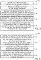
- FIG. 4 illustrates an embodiment of a process 80 by which the tubular welding wire 50 may be manufactured.
- the process 80 merely provides an example of manufacturing a tubular welding wire 50; however, in other embodiments, other methods of manufacturing may be used to produce the tubular welding wire 50 without spoiling the effect of the present approach. That is, for example, in certain embodiments, the tubular welding wire 50 may be formed via a roll-forming method or via packing the core composition into a hollow metallic sheath.
- the illustrated process 80 begins with a flat metal strip being fed (block 82) through a number of dies that shape the strip into a partially circular metal sheath 52 (e.g., producing a semicircle or trough).
- the metal strip After the metal strip has been at least partially shaped into the metal sheath 52, it may be filled (block 84) with the filler (i.e., the granular core 54), such as the formulations E1-E12 for the granular core 54 filler discussed with respect to Table 1. That is, the partially shaped metal sheath 52 may be filled with various powdered alloying, arc stabilizing, slag forming, deoxidizing, and/or filling components.
- the disclosed tubular welding wire 50 may be completely free or substantially free of manganese or may be a low manganese (e.g., less than approximately 0.4% manganese by weight) welding wire.
- the granular core 54 of the tubular welding wire 50 may be completely free or substantially free of manganese, and only the metal sheath 52 includes (e.g., approximately 0.35%, approximately 0.26%, or less) manganese.
- the partially shaped metal sheath 52 may then be fed through (block 86) one or more devices (e.g., drawing dies or other suitable closing devices) that may generally close the metal sheath 52 such that it substantially surrounds the granular core material 54 (e.g., forming a seam 58). Additionally, the closed metal sheath 52 may subsequently be fed through (block 88) a number of devices (e.g., drawing dies or other suitable devices) to reduce the circumference of the tubular welding wire 50 by compressing the granular core material 54.
- devices e.g., drawing dies or other suitable closing devices
Landscapes
- Engineering & Computer Science (AREA)
- Mechanical Engineering (AREA)
- Chemical & Material Sciences (AREA)
- Inorganic Chemistry (AREA)
- Physics & Mathematics (AREA)
- Plasma & Fusion (AREA)
- Nonmetallic Welding Materials (AREA)
Description
- The invention relates generally to welding and, more specifically, to a flux-cored tubular welding wire as defined in the preamble of claim 1, and to a method of manufacturing such a welding wire as defined in claim 7.
- A flux-cord tubular welding wire as defined in the preamble of claim 1 is known from
CN 102 233 498 A . It is made of a steel belt and flux-cored powder, wherein the flux-cored powder comprises the following components in parts by weight: 4-10 parts of sintering powder, 0.1-0.7 part of Fe3O4, 0-1.0 part of TiO2, 0.1-0.5 part of Al, 0-0.4 part of Ti, 0.1-0.5 part of Si, 2.0-2.5 parts of Mn and 1.0-2.0 parts of Fe.EP 2 343 149 A1 discloses a flux-cored nickel-based alloy wire comprising a Mn content of 1,0 percent by mass or less. - Welding is a process that has become ubiquitous in various industries for a variety of applications. For example, welding is often used in applications such as shipbuilding, offshore platform, construction, pipe mills, and so forth. Certain welding techniques (e.g., Gas Metal Arc Welding (GMAW), Gas-shielded Flux Core Arc Welding (FCAW-G), Self-shielded Flux Core Arc Welding (FCAW-S), and Submerged Arc Welding (SAW)), typically employ a welding electrode in the form of welding wire. Welding wire may generally provide a supply of filler metal for the weld as well as provide a path for the current during the welding process.
- The present invention provides a flux-cored tubular welding wire as defined in claim 1.
- The present invention also provides a method of manufacturing a tubular welding wire as defined in claim 7.
- Further features are disclosed in the subclaims..
- These and other features, aspects, and advantages of the present invention will become better understood when the following detailed description is read with reference to the accompanying drawings in which like characters represent like parts throughout the drawings, wherein:
-
FIG. 1 is a block diagram of a gas metal arc welding (GMAW) system; -
FIG. 2 is a cross-sectional view of a tubular welding wire, in accordance with embodiments of the present disclosure; -
FIG. 3 is a process by which the tubular welding wire may be used to weld a workpiece; and -
FIG. 4 is a process for manufacturing the tubular welding wire, in accordance with embodiments of the present disclosure. - One or more specific embodiments of the present disclosure will be described below. In an effort to provide a concise description of these embodiments, all features of an actual implementation may not be described in the specification. It should be appreciated that in the development of any such actual implementation, as in any engineering or design project, numerous implementation-specific decisions must be made to achieve the developers' specific goals, such as compliance with system-related and business-related constraints, which may vary from one implementation to another. Moreover, it should be appreciated that such a development effort might be complex and time consuming, but would nevertheless be a routine undertaking of design, fabrication, and manufacture for those of ordinary skill having the benefit of this disclosure.
- When introducing elements of various embodiments of the present disclosure, the articles "a," "an," "the," and "said" are intended to mean that there are one or more of the elements. The terms "comprising," "including," and "having" are intended to be inclusive and mean that there may be additional elements other than the listed elements. It should be appreciated that, as used herein, the term "tubular welding electrode" or "tubular welding wire" may refer to any welding wire or electrode having a metal sheath and a granular or powdered core, such as metal-cored or flux-cored welding electrodes. It should be appreciated that the term "tubular," as used herein, may include various shapes of welding wire, including round, elliptical, square, polygonal, or any other suitable shape.
- Certain types of welding wire (e.g., tubular welding wire) may include one or more components (e.g., flux, arc stabilizers, or other additives) that may generally alter the welding process and/or the properties of the resulting weld. For example, rutile is a mineral, primarily composed of titanium dioxide (TiO2), which may also include compounds of iron (Fe), niobium (Nb), tantalum (Ta), vanadium (V), and/or other impurities. Furthermore, rutile may be included in some types of welding wires, such as T-1 welding wires (e.g., AWS A5.20 EXXT-1, A5.29 EXXT1-YY, A5.36 EXXT-1, and EXXT1 -YY). By further example, certain types of welding wires may include a substantial quantity of manganese (Mn) (e.g., greater than 0.5% by weight) to function as a deoxidizer and/or an alloying metal for the resulting weld. That is, this manganese content may react with oxygen near the welding environment to form oxides of manganese (e.g., manganese oxide (MnO) and/or manganese dioxide (MnO2)) that flow into the slag and/or transfer into the weld pool becoming incorporated into the weld metal to improve the mechanical properties of the resulting weld. In general, manganese may form alloys with certain metals (e.g., steel) to provide improved strength, ductility, and toughness. In certain environments, the manganese may act as a deoxidizer reacting with oxygen (e.g., from the atmosphere) in order to block (e.g., limit or prevent) this oxygen from remaining in the weld deposit. Similarly, manganese may react with and remove sulfur from the welding environment. Furthermore, manganese in a welding wire may help to control the weld puddle (e.g., by improving the wetting of the workpiece).
- However, despite these effects, it may be desirable, in certain situations, to utilize a low-manganese welding wire. For example, a welding wire having low manganese content (e.g., less than 0.5%, less than 0.35%, or less than 0.26% manganese by weight) may volatilize only a small quantity of manganese during the welding operation. Accordingly, the present disclosure is directed toward systems and methods for welding wires having low manganese content that may be used to produce welds having a low manganese content (e.g., less than approximately 0.5%, less than approximately 0.4%, or less than 0.3% manganese by weight) while still providing suitable weld properties (e.g., tensile strength, ductility, toughness, and so forth). In other words, the presently disclosed welding wires generally maintain the weld quality (e.g., a weld having a reasonable level of inclusions, good strength, and/or good toughness) despite the low manganese content.
- According to the present invention, the disclosed welding wires achieve the aforementioned welding properties and weld quality despite the low manganese content, at least in part, through the use of a purified, agglomerated titanium dioxide component. The granular core of presently disclosed tubular welding wire embodiments includes pigment-grade TiO2 that has been agglomerated with binding and/or drying agents (e.g., sodium silicate, potassium silicate, lithium fluoride, and/or other binding or drying agents). Furthermore, certain embodiments of the presently disclosed welding wire include high levels of deoxidizers (e.g., zirconium, aluminum, magnesium, silicon, and/or other suitable deoxidizers) to generally deter (e.g., block) oxygen incorporation into the weld metal. Accordingly, as set forth below, the presently disclosed tubular welding wires enable the formation of weld deposits having relatively low manganese content (e.g., generally less than approximately 0.5% by weight) while still affording good weld properties (e.g., tensile strength, ductility, toughness, and so forth).
- Turning to the figures,
FIG. 1 illustrates an example of a gas metal arc welding (GMAW)system 10 that utilizes tubular welding wire, in accordance with the present disclosure. It should be appreciated that, while the present discussion may focus specifically on the GMAWsystem 10 illustrated inFIG. 1 , the presently disclosed welding wire may benefit a number of different welding processes (e.g., FCAW-S, FCAW-G, GTAW, SAW, or similar welding processes) that use a welding wire. Thewelding system 10 includes awelding power source 12, awelding wire feeder 14, agas supply system 16, and awelding torch 18. Thewelding power source 12 generally supplies power to thewelding system 10 and may be coupled to thewelding wire feeder 14 via acable bundle 20. Thewelding power source 12 may also be coupled to aworkpiece 22 using alead cable 24 having aclamp 26. In the illustrated embodiment, thewelding wire feeder 14 is coupled to thewelding torch 18 via acable bundle 28 in order to supply consumable, tubular welding wire (e.g., the welding electrode) and power to thewelding torch 18 during operation of thewelding system 10. In another embodiment, thewelding power source 12 may couple and directly supply power to thewelding torch 18. - The
welding power source 12 may generally include power conversion circuitry that receives input power from an alternating current power source 30 (e.g., an AC power grid, an engine/generator set, or a combination thereof), conditions the input power, and provides DC or AC output power via thecable 20. As such, thewelding power source 12 may power thewelding wire feeder 14 that, in turn, powers thewelding torch 18, in accordance with demands of thewelding system 10. Thelead cable 24 terminating in theclamp 26 couples thewelding power source 12 to theworkpiece 22 to close the circuit between thewelding power source 12, theworkpiece 22, and thewelding torch 18. Thewelding power source 12 may include circuit elements (e.g., transformers, rectifiers, switches, and so forth) capable of converting the AC input power to a direct current electrode positive (DCEP) output, direct current electrode negative (DCEN) output, DC variable polarity, pulsed DC, or a variable balance (e.g., balanced or unbalanced) AC output, as dictated by the demands of thewelding system 10. It should be appreciated that the presently disclosed tubular welding wire may enable improvements to the welding process (e.g., improved arc stability and/or improved weld quality) for a number of different power configurations. - The illustrated
welding system 10 includes agas supply system 16 that supplies a shielding gas or shielding gas mixtures from one or moreshielding gas sources 17 to thewelding torch 18. In the depicted embodiment, thegas supply system 16 is directly coupled to thewelding torch 18 via agas conduit 32. In another embodiment, thegas supply system 16 may instead be coupled to thewire feeder 14, and thewire feeder 14 may regulate the flow of gas from thegas supply system 16 to thewelding torch 18. In other embodiments, such as certain FCAW-S and SAW systems that do not rely on an externally supplied shielding gas, thewelding system 10 may not include thegas supply system 16. A shielding gas, as used herein, may refer to any gas or mixture of gases (e.g., inert or active gasses) that may be provided to the arc and/or weld pool in order to provide a particular local atmosphere (e.g., to shield the arc, improve arc stability, limit the formation of metal oxides, improve wetting of the metal surfaces, alter the chemistry of the weld deposit, and so forth). - The shielding gas flow may be a shielding gas or shielding gas mixture (e.g., argon (Ar), helium (He), carbon dioxide (CO2), oxygen (O2), nitrogen (N2), hydrogen (H2), similar suitable shielding gases, or any mixtures thereof). For example, a shielding gas flow (e.g., delivered via the gas conduit 32) may include Ar, CO2, Ar/CO2 mixtures (e.g., 75% Ar and 25% CO2, 90% Ar and 10% CO2, and so forth), Ar/CO2/O2 mixtures, Ar/He mixtures, and so forth. Further, it may be appreciated that, as set forth in detail below, certain shielding gases (e.g., certain Ar/CO2 mixtures, such as 90% Ar/ 10% CO2) may reduce a total amount of welding fumes that may be generated during the welding operation.
- Accordingly, the illustrated
welding torch 18 generally receives the tubular welding wire from thewelding wire feeder 14, power from thewelding power source 12, and a shielding gas flow from thegas supply system 16 in order to perform GMAW of theworkpiece 22. During operation, thewelding torch 18 may be brought near theworkpiece 22 so that anarc 34 may be formed between the consumable welding electrode (i.e., the welding wire exiting a contact tip of the welding torch 18) and theworkpiece 22. Additionally, as discussed below, by controlling the composition of the tubular welding wire, the chemical and mechanical properties of the resulting weld may be varied. The tubular welding wire includes a deoxidizing component to react with and remove undesired species (e.g., oxygen, metal oxides, or other undesired oxygen species) from the weld environment. The tubular welding wire further includes alloying components to contribute species (e.g., copper, molybdenum, silicon, carbon, or other suitable alloying components) to the weld pool, affecting the mechanical properties (e.g., strength and toughness) of the weld. Furthermore, certain components of the tubular welding wire may also provide additional shielding atmosphere near thearc 34, affect the transfer properties of thearc 34, clean the surface of theworkpiece 22, and so forth. - A cross-section of an embodiment of the presently disclosed welding wire is illustrated in
FIG. 2. FIG. 2 illustrates atubular welding wire 50 having ametallic sheath 52 that encapsulates a granular orpowdered core 54, which may also be referred to as filler. Themetallic sheath 52 is manufactured from low-carbon steel or low-alloy steel. Themetal sheath 52 provides 70% to 90% of the total weight of thetubular welding wire 50. Themetallic sheath 52 may include additives or impurities (e.g., iron oxides, carbon, manganese, silicon, nickel, or similar compounds or elements) that may be selected to provide desired properties for thetubular welding wire 50 as well as the weld bead. For example, certain embodiments of thetubular welding wire 50 may include ametallic sheath 52 having less than approximately 0.02% carbon by weight. In other embodiments, themetallic sheath 52 may include between approximately 0.02% and approximately 0.16% carbon by weight. - Furthermore, in certain embodiments, the
metallic sheath 52 of thetubular welding wire 50 may include relatively low manganese content. In certain embodiments, the amount of manganese that may be present in themetallic sheath 52 may be between approximately 0.01% and approximately 0.5% by weight (e.g., approximately 0.35% by weight or approximately 0.26% by weight), while thegranular core 54 may be completely free or substantially free from manganese (e.g., including little or no metallic manganese and/or including little or no manganese compounds). For example, in certain embodiments, thegranular core 54 may include less than 0.1%, less than 0.05%, less than 0.04%, less than 0.03%, less than 0.02%, less than 0.01%, or approximately 0% (e.g., none or only trace impurity quantities) manganese by weight. As such, a number of the presently disclosed tubular welding wire embodiments have a manganese content (e.g., manganese metal or alloys, or manganese compounds, or both) less than approximately 0.35% or less than approximately 0.4% by weight. Further, in certain embodiments, themetallic sheath 52 may be completely free or substantially free (e.g., none or only trace impurity quantities) from manganese alloys, which may provide atubular welding wire 50 that is completely free or substantially free of manganese metals and/or manganese compounds (e.g., manganese oxide). - The
granular core 54 of the illustratedtubular welding wire 50 generally is a compacted powder with a composition that, as discussed below, includes various components that each may serve at least one role as an alloying component, arc stabilizer, slag forming component, deoxidizer, and/or filler during the welding process. These components of thegranular core 54 may be homogenously or non-homogenously (e.g., in clumps or clusters 56) disposed within thegranular core 54. Thegranular core 54 provides between 10% and 30% of the total weight of thetubular welding wire 50. Furthermore, as discussed in detail below, in certain embodiments, one or more components (e.g., certain arc stabilizing and/or slag forming components) may be prepared and included in thegranular core 54 as agglomerates (e.g., sintered and/or formed into frits). It should be noted that the term "agglomerate" or "frit," as used herein, refers to a mixture of compounds that have been fired or heated in a calciner or oven such that the components of the mixture are in intimate contact with one another. It should be appreciated that the agglomerate or frit may have subtly or substantially different chemical and/or physical properties than the individual components of the mixture used to form the agglomerate. For example, an agglomerate may generally be better suited for the weld environment (e.g., drier and/or better powder flow) than a non-agglomerated form of the same component. - Tables 1, 2, and 3 are set forth below for various embodiments of the
tubular welding wire 50. More specifically, Table 1 includes a non-limiting list of twelve example formulations (e.g., E1-E12) for thegranular core 54 for the presently disclosedtubular welding wire 50. Table 2 includes computed chemical composition for each of the example formulations (E1-E12) of thegranular core 54 based on the components set forth in Table 1. Furthermore, Table 3 includes chemical and mechanical analysis results for weld deposits formed using each of the welding wire embodiments set forth in Table 1. The welding wire embodiments E1-E12 may correspond to one or more AWS standards for welding wire. That is, E1 may correspond to AWS A5.20 E71T-1C; E2 may correspond to AWS A5.20 E71T-1M; E3 and E9 may correspond to AWS A5.29 E71T1-Ni1C (G); E4 and E10 may correspond to AWS A5.29 E71T1-Ni1M(G); E5 may correspond to AWS A5.29 E81T1-NiC; E6 may correspond to AWS A5.29 E81T1-Ni1M; E7 may correspond to AWS A5.29 E81T1-K2C (G); E8 may correspond to AWS A5.29 E81T1-K2M (G); and E11 and E12 may correspond to AWS A5.20 E71T-G H8. - For the embodiments E1-E8 of Table 1, the
metallic sheath 52 may account for approximately 84% of the weight of thetubular welding wire 50, while the remaining approximately 16% of the weight of the tubular welding wire may be contributed by thegranular core 54. For embodiments E9-E12 of Table 1, themetallic sheath 52 may account for approximately 85% of the weight of thetubular welding wire 50, while the remaining approximately 15% may be contributed by the granular core. Further, for the embodiments E1-E8, themetallic sheath 52 may include approximately 0.35% manganese, while embodiments E9-E12 may include a metallic sheath having approximately 0.26% manganese. It should be appreciated that, while each component in Table 1 may be listed as serving a particular purpose (e.g., as an alloying agent, arc stabilizer, slag former, deoxidizer, or filler), each component may actually serve more than one role in the welding process. That is, for example, TiO2 provided to the weld environment by the agglomerated titanium dioxide and/or the rutile powder may actually provide stability to thearc 34 in addition to aiding in slag formation. By further example, certain deoxidizing components (e.g., aluminum, magnesium, and/or zirconium) may bind strongly to oxygen, and sometimes nitrogen as well, from the welding atmosphere and form at least a portion of the slag around the weld bead. Similarly, certain deoxidizing components may also bind strongly to sulfur, which may come from the workpiece or from the welding consumable (e.g., as an impurity in themetallic sheath 52 or components of the granular core 54). As such, it should be appreciated that these components may be otherwise classified (e.g., as arc stabilizers, slag forming components, and/or deoxidizers) without altering the present invention.Table 1. Example formulations for the granular core 54 for embodiments E1-E12 oftubular welding wire 50. Values are in weight percent relative to the total weight of thegranular core 54.Role Component E1 E2 E3 E4 E5 E6 E7 E8 E9 E10 E11 E12 Alloying Ferro-molybdenum metal powder 0.0 0.0 0.0 0.0 1.5 0.0 0.0 0.0 0.0 0.0 0.0 0.0 Nickel powder 2.5 2.5 5.2 6.2 5.5 5.5 11.5 10.5 6.8 6.3 9.0 9.0 Copper powder 0.0 0.0 0.0 0.0 0.0 1.5 0.0 0.0 0.0 0.0 0.0 0.0 High carbon iron powder 10.0 2.0 0.0 2.0 9.0 9.0 10.0 7.5 2.0 3.7 0.0 0.0 Arc Stabilizing Iron oxides 0.0 3.5 0.0 7.0 0.0 3.5 0.0 3.5 0.0 7.5 7.5 4.1 Potassium fluorosilicate 1.1 0.0 1.1 0.0 1.1 0.0 1.1 0.0 1.1 0.0 0.0 0.0 Sodium titanate frit 9.0 11.0 9.0 11.0 9.0 11.0 9.0 11.0 9.6 11.7 0.0 0.0 Sodium titanate frit (pigment grade TiO2) 0.0 0.0 0.0 0.0 0.0 0.0 0.0 0.0 0.0 0.0 11.7 0.0 Lithium oxide agglomerate 0.0 0.0 0.0 0.0 0.0 0.0 0.0 0.0 0.0 0.0 0.0 5.5 Slag Forming Rutile powder 5.0 0.0 5.0 0.0 5.0 0.0 5.0 0.0 5.0 0.0 0.0 0.0 Manganous oxide powder 0.0 4.0 0.0 0.0 0.0 5.0 0.0 4.0 0.0 0.0 0.0 0.0 Agglomerated titanium dioxide 42.3 43.0 42.3 43.0 42.3 43.0 42.3 43.0 45.1 45.8 45.7 55.3 Deoxidizing Magnesium powder 0.5 0.0 0.5 0.0 0.5 0.0 0.5 0.0 0.9 0.0 0.0 0.0 Aluminum-zirconium metal powder 0.5 0.0 0.5 0.0 0.0 0.0 0.0 0.0 1.0 0.0 1.1 1.1 Ferro-zirconium-silicon powder 8.7 4.5 8.7 4.5 9.3 4.5 9.3 4.5 8.3 5.3 3.1 3.1 Aluminum-magnesium metal powder 3.8 4.3 3.8 4.3 3.7 4.3 3.7 4.3 3.3 4.3 3.7 3.7 Aluminum powder 0.0 0.6 0.0 0.6 0.0 0.0 0.0 0.0 0.0 0.0 0.0 0.0 Ferro-silicon metal powder 0.0 4.7 0.0 4.7 0.0 6.0 0.0 4.7 0.0 4.1 0.0 0.0 Calcium silicon powder 0.0 0.0 0.0 0.0 0.0 0.0 0.0 0.0 0.0 0.0 3.5 3.5 Filling iron powder 16.6 19.9 23.9 16.7 13.1 6.7 7.6 7.0 16.9 11.3 14.7 14.7 Table 2. Computed chemical composition for each of the example formulations (E1 - E12) of the granular core 54 based on the components set forth in Table 1. Values are in weight percent relative to the total weight of thegranular core 54. Further, the list is not exhaustive and, as such, the amounts of each constituent may not sum up to unity.Chemical name E1 E2 E3 E4 E5 E6 E7 E8 E9 E10 E11 E12 Aluminum (Al) 2.13 2.77 2.13 2.76 1.85 2.18 1.85 2.17 2.11 2.16 2.42 2.42 Carbon (C) 0.43 0.11 0.06 0.11 0.39 0.36 0.43 0.31 0.13 0.17 0.06 0.06 Copper (Cu) 0.00 0.00 0.00 0.00 0.00 1.50 0.00 0.00 0.00 0.00 0.00 0.00 Iron (Fe) 27.04 24.91 24.76 21.46 23.22 19.14 18.14 17.29 19.63 17.46 15.20 15.20 Magnesium (Mg) 2.40 2.15 2.40 2.15 2.35 2.16 2.35 2.16 2.54 2.14 1.84 1.84 Manganese (Mn) 0.03 0.00 0.00 0.01 0.03 0.00 0.04 0.00 0.01 0.01 0.00 0.00 Molybdenum (Mo) 0.00 0.00 0.00 0.00 0.94 0.00 0.00 0.00 0.00 0.00 0.00 0.00 Nickel (Ni) 2.49 2.50 5.18 6.17 5.48 5.51 11.46 10.51 6.77 6.27 8.96 8.96 Silicon (Si) 4.46 4.60 4.44 4.58 4.76 5.26 4.76 4.61 4.23 4.70 3.65 3.65 Zirconium (Zr) 3.62 1.73 3.62 1.73 3.57 1.74 3.57 1.73 3.73 2.04 1.78 1.78 Ferrous/ferric oxide (FexOy) 0.00 3.52 0.00 7.00 0.00 3.52 0.00 3.52 0.00 7.50 7.50 7.49 Maganous oxide (MnO) 0.00 3.30 0.00 0.00 0.00 4.13 0.00 3.30 0.00 0.00 0.00 0.00 Potassium oxide (K2O) 0.36 0.36 0.36 0.36 0.36 0.36 0.36 0.36 0.38 0.38 0.38 0.46 Sodium oxide (Na2O) 1.55 1.81 1.55 1.79 1.55 1.81 1.55 1.80 1.65 1.91 1.91 0.65 Silicon dioxide (SiO2) 2.80 3.07 2.80 2.95 2.80 3.11 2.80 3.07 2.98 3.14 3.13 4.06 Titanium dioxide (TiO2) 50.81 48.32 50.81 48.11 50.81 48.38 50.81 48.35 53.78 51.20 51.11 50.16 Lithium fluoride (LiF) 0.81 0.82 0.81 0.82 0.81 0.82 0.81 0.82 0.86 0.87 0.87 1.05 Potassium fluorosilicate (K2SiF6) 1.10 0.00 1.10 0.00 1.10 0.00 1.10 0.00 1.10 0.00 0.00 0.00 Calcium 0.00 0.00 0.00 0.00 0.00 0.00 0.00 0.00 0.00 0.00 1.01 1.01 Lithium oxide 0.00 0.00 0.00 0.00 0.00 0.00 0.00 0.00 0.00 0.00 0.00 1.03 - As set forth in Table 1, the
granular core 54 of thetubular welding wire 50 includes between 4% and 18% alloying components by weight. For example, thetubular welding wire 50 includes agranular core 54 having ferro-molybdenum metal powder, nickel powder, copper powder, and/or high-carbon (e.g., between approximately 3.2% and 3.9% carbon by weight) iron powder. As set forth in Table 2, thetubular welding wire 50 may include agranular core 54 having between approximately 0% and approximately 1.5% copper, between approximately 2% and approximately 12% nickel, between approximately 0% and approximately 1% molybdenum, and/or between approximately 0% and approximately 1% carbon by weight. While these alloying components may otherwise contribute to the welding process (e.g., as arc stabilizers, slag formers, and/or deoxidizers), generally speaking, these alloying components are substantially incorporated (e.g., greater than 90% incorporated) into the weld metal to affect the properties (e.g., strength, ductility, corrosion resistance, and so forth) of the weld bead and the surroundingworkpiece 22. - Furthermore, as set forth in Table 1, the
granular core 54 of thetubular welding wire 50 includes between 10% and 15% arc stabilizing components by weight. For example, thetubular welding wire 50 includes agranular core 54 having iron oxides, potassium fluorosilicate, sodium titanate frit (e.g., made using either rutile or pigment-grade TiO2), and/or lithium oxide agglomerate. As set forth in Table 2, certain embodiments of thetubular welding wire 50 may include agranular core 54 having between approximately 0% and 7.5% iron oxides, between approximately 0% and 2% potassium fluorosilicate, between approximately 0% and approximately 12% sodium titanate frit, and between 0% and 6% lithium oxide agglomerate by weight. Again, while these components may otherwise contribute to the welding process (e.g., as slag formers and/or deoxidizers), these arc stabilizers may generally provide species to the arc that readily ionize, enabling a more consistent and/orcontrollable arc 34 to the surface of theworkpiece 22. The presently disclosed sodium titanate frit may be a sintered mixture of sodium titanate and lithium fluoride and/or sodium silicate that may be better suited for the weld environment (e.g., drier and/or better powder flow) than non-agglomerated sodium titanate. As indicated in Table 1, in certain embodiments, the sodium titanate may be made from rutile and, accordingly, may have one or more of the aforementioned impurities that rutile may commonly include. In other embodiments indicated in Table 1, the sodium titanate may instead be made from pigment grade TiO2, which may lack one or more of these impurities. By specific example, an embodiment of a pigment-grade sodium titanate frit may include approximately 11.8% sodium oxide, approximately 5.7% silica, and approximately 82.5% pigment-grade TiO2. Similarly, as indicated in Table 1, certain embodiments may include a lithium agglomerate that may be a sintered mixture of lithium oxide, iron oxides, sodium oxide, and silica, which may be better suited for the weld environment (e.g., drier and/or better powder flow) than a non-agglomerated mixture of these components. By specific example, in certain embodiments, the lithium agglomerate may include approximately 18.7% lithium oxide, approximately 61.6% iron oxides, approximately 0.2% sodium oxide, and approximately 19.5% silica. - Additionally, as set forth in Table 1, the
granular core 54 of thetubular welding wire 50 includes between 40% and 50% slag forming components by weight. Thetubular welding wire 50 includes agranular core 54 having rutile powder, manganous oxide powder, and/or agglomerated titanium dioxide. For example, certain embodiments of the presently disclosedwelding wire 50 may have agranular core 54 that includes between approximately 3% and approximately 5% manganese oxide powder by weight. Other embodiments of the presently disclosedwelding wire 50 may have agranular core 54 that includes substantially no (e.g., approximately 0%) manganese oxide powder by weight. Accordingly, as set forth in Table 2, , this results ingranular cores 54 and/ortubular welding wires 50 having a manganese content (e.g., as a metal and/or as a component of a chemical compound) less than 3.5%, 3%, 2.5%, 2%, 1%, 0.5%, 0.35%, 0.05%, 0.03%, 0.01%, or even 0.001% by weight. - In terms of other slag forming components, in certain embodiments, the
granular core 54 of thetubular welding wire 50 may include between approximately 45% and approximately 55% titanium dioxide by weight (e.g., from the rutile and/or agglomerated titanium dioxide sources). Accordingly, thetubular welding wire 50 includes between 6% and 8% pigment-grade TiO2 by weight. It should be appreciated that, the TiO2 used to form the presently disclosed agglomerated titanium dioxide is a pigment-grade TiO2 (e.g., greater than 95%, 99%, 99.9%, or 99.99% TiO2) that may lack or have lower levels of one or more impurities typically found in rutile (e.g., iron, niobium, tantalum, vanadium, and/or other impurities). That is, pigment grade TiO2 is generally both purified and milled, in contrast to lower purity TiO2, such as milled rutile. - Furthermore, in certain embodiments, this pigment-grade TiO2 may be sintered with one or more drying and/or binding agents (e.g., lithium fluoride, and/or sodium silicate) to form the agglomerated titanium dioxide component of the
granular core 54. For example, in certain embodiments of the presently disclosedwelding wire 50, an agglomerated titanium dioxide component may be formed by dry mixing purified TiO2 powder and purified (e.g., precipitated grade) lithium fluoride for a period of time (e.g., 10 min). Then, as mixing continues, a concentrated aqueous solution of sodium silicate and a concentrated aqueous solution of potassium silicate may be slowly added to the dry mixture along with, in certain situations, a small quantity of water until a desired consistency is achieved (e.g., mixture begins to "ball"). After mixing for an additional period of time (e.g., 3 to 5 min), in certain embodiments, the wet mixture may be disposed in an oven (e.g., a direct fired kiln) and heated to approximately 1200 °F to approximately 1600 °F for approximately 15 to 25 minutes (or heated to similar temperatures in a pan for approximately 2 hours). In certain embodiments, the TiO2 agglomerate may be made from approximately 81.3% purified TiO2, approximately 11% sodium silicate, approximately 6% potassium silicate, and approximately 1.7% lithium fluoride. Once the agglomerate has been formed (e.g., after firing), in certain embodiments, the agglomerate may consist of pigment-grade TiO2, silica, potassium oxide, sodium oxide and lithium fluoride (e.g., approximately 90.7% TiO2, approximately 5.4% silica, approximately 1.2% sodium oxide, approximately 0.8% potassium oxide, and approximately 1.9% lithium fluoride). While not desiring to be bound by theory, it is believed that using a combination of both sodium and potassium silicates, as presently disclosed, provides a TiO2 agglomerate that may be especially resistant to accumulating moisture from the surrounding environment. Additionally, in certain embodiments, using lithium fluoride in combination with these two silicates increases the moisture resistance of the TiO2 agglomerate and enables the formation of a harder and/or denser TiO2 agglomerate. - Additionally, as set forth in Table 1, the
granular core 54 of thetubular welding wire 50 includes between 10% and 15% deoxidizers by weight. Thetubular welding wire 50 includes agranular core 54 having magnesium powder, aluminum-zirconium metal powder, ferro-zirconium-silicon powder, aluminum-magnesium metal powder, aluminum powder, ferro-silicon metal powder, and/or calcium silicon powder. By specific example, certain embodiments oftubular welding wire 50 may have agranular core 54 that includes aluminum-zirconium metal powder and/or ferro-zirconium-silicon powder as deoxidizing components. In certain embodiments, the calcium silicon powder may include approximately 30% calcium, approximately 60% silicon, approximately 6% iron, and approximately 1% carbon by weight of the powder. In certain embodiments, as set forth in Table 2, thegranular core 54 of thetubular welding wire 50 may include between approximately 0% and approximately 3% aluminum, between approximately 0% and approximately 3% magnesium, between approximately 0% and approximately 4% zirconium, and/or between approximately 0% and approximately 6% silicon by weight. While these components may otherwise contribute to the welding process (e.g., as arc stabilizers or slag formers), these deoxidizing components are generally selected to strongly bind oxygen in order to block (e.g., limit or prevent) this oxygen from remaining in the weld pool and weakening the weld deposit. - Furthermore, as set forth in Table 1, the
granular core 54 of thetubular welding wire 50 includes between 5% and 25% filler metal by weight. Thetubular welding wire 50 includes agranular core 54 having iron powder as the filler metal. As set forth in Table 2, certain embodiments of thetubular welding wire 50 may have agranular core 54 including between approximately 15% and approximately 30% iron by weight. While the iron powder may otherwise contribute to the welding process (e.g., as an arc stabilizer, slag former, and/or deoxidizer), the iron powder may generally provide a substantial portion of the metal used to form the weld on theworkpiece 22. As such, most of the iron powder included in thegranular core 54 may be incorporated into and form the weld deposit. - Table 3 includes chemical and mechanical analysis results for weld deposits formed using the welding wire embodiments (e.g., embodiments E1-E12) set forth in Tables 1 and 2. It should be noted that the elements included in Table 3 include values in the form of weight percentages for a non-exhaustive list of elements; other elements (e.g., Fe) and other trace impurities (e.g., arsenic (As)) may also be present within the weld metal. In general, it should be noted that all of the tubular welding wire embodiments provide weld deposits having relatively low oxygen content (e.g., between approximately 0% and approximately 0.15%, between approximately 0.05% and approximately 0.10%, or less than approximately 0.09% by weight) and relatively low nitrogen content (e.g., between approximately 0% and approximately 0.01%, between approximately 0.004% and approximately 0.009%, or less than 0.01% by weight). Additionally, in certain embodiments of the
tubular welding wire 50, the use of the pigment grade TiO2 in the agglomerated titanium dioxide generally enables the formation of weld deposits having relatively low vanadium content (e.g., between approximately 0.006% and approximately 0.008% or less than approximately 0.009% by weight) and relatively low niobium content (e.g., between approximately 0.003% and approximately 0.005% or less than approximately 0.006% by weight), which may offer advantages to the weld deposit. Furthermore, as set forth in Table 3, certain embodiments of thetubular welding wire 50 may form weld deposits having a manganese content between approximately 0.2% and approximately 0.5%, between approximately 0.25% and approximately 0.4%, or between approximately 0.3% and approximately 0.4% by weight. In contrast, other T-1 welding wires (e.g., AWS A5.20 EXXT-1, A5.29 EXXT1-YY, A5.36 EXXT-1, and EXXT1-YY) may form weld deposits having greater than approximately 0.75% manganese by weight, while typical self-shielded welding wires may generally form weld deposits having greater than approximately 0.5% manganese. Accordingly, the presently disclosedtubular welding wires 50 enable the formation of weld deposits having substantially lower manganese content (e.g., less than 0.5%, such as 0.15% or even 0.05% manganese by weight) than weld deposits from other welding wires, while still maintaining good weld properties. - Table 3 also lists mechanical properties for each of the example weld deposits formed using the welding wire embodiments (e.g., embodiments E1-E12) listed in Table 1. Specifically, Table 3 includes mechanical property measurements for yield strength, tensile strength, percent elongation, and Charpy-V-Notch (CVN) values at -20 °F (-29°C) and -40 °F (-40°C) as determined based on AWS A5.20 (e.g., E71T1-GM), A5.36, or another suitable standard. In general, the example weld deposits may demonstrate yield strengths from approximately 60 ksi (414 MPa) to approximately 75 ksi (517 MPa), tensile strengths from approximately 70 ksi (483 MPa) to approximately 85 ksi (586 MPa) percent elongation from approximately 20% to approximately 35%, CVN from approximately 40 ft-lbs (54 J) to approximately 105 ft-lbs (142 J) at - 20 °F (-29°C), and CVN from approximately 35 ft-lbs (48 J) to approximately 95 ft-lbs (129 J) at -40 °F (-40°C). For example, in certain embodiments, the weld deposit demonstrated a CVN of greater than 65 ft-lbs (88 J), greater than 70 ft-lbs (95 J), greater than 75 ft-lbs (102 J), greater than 80 ft-lbs (109 J) greater than 85 ft-lbs (115 J), greater than 90 ft-lbs (122 J), or greater than 100 ft-lbs (136 J) at -20 °F (-29°C). By further example, in certain embodiments, the weld deposit demonstrated a CVN of greater than 45 ft-lbs (61 J), greater than 50 ft-lbs (68 J), greater than 70 ft-lbs (95 J), greater than 75 ft-lbs (102 J), greater than 80 ft-lbs (109 J), greater than 85 ft-lbs (115 J), or greater than 90 ft-lbs (122 J) at -40 °F (-40°C). Further, for embodiments E11 and E12, the CVN at -60 °F (-51°C) is approximately 100 ft-lbs (136 J) as listed in Table 3. It should be noted that despite the relatively low manganese content determined for the weld deposits E1-E12 (e.g., less than approximately 0.5%), the weld deposits possess relatively high toughness and a suitable tensile strength for the classification type, as compared to conventional welding wires.
Table 3. Example elemental analyses and mechanical test results for weld deposits E1-E12 formed using the corresponding tubular welding wire embodiments E1-E12 of Table 1. Elemental values are in weight percent relative to the total weight of the weld deposit. Weld deposits were formed using the following parameters: Amps: 260; Volts: 26-28; DCEP; Wire Feed Speed: 450 inches per minute; Electrical Stickout: 0.75 in.; Travel Speed: 10 inches per minute; Angle: 45°; Position: 1g; Shielding Gas: 100% CO2, 75% Argon and 25% CO2, or 90% Argon and 10% CO2. N/A denotes measurements that are not presently available. Element E1 E2 E3 E4 E5 E6 E7 E8 E9 E10 E11/12 Carbon (C) 0.067 0.032 0.020 0.028 0.075 0.077 0.071 0.058 0.035 0.080 0.027 Manganese (Mn) 0.205 0.388 0.206 0.206 0.222 0.429 0.229 0.392 0.251 0.217 0.245 Phosphorus (P) 0.008 0.010 0.008 0.006 0.011 0.010 0.009 0.013 0.009 0.012 0.011 Sulfur (S) 0.008 0.008 0.008 0.008 0.010 0.010 0.008 0.011 0.008 0.013 0.008 Silicon (Si) 0.366 0.496 0.427 0.486 0.524 0.607 0.451 0.485 0.488 0.478 0.385 Copper (Cu) 0.045 0.047 0.047 0.045 0.050 0.282 0.042 0.048 0.018 0.014 0.016 Chromium (Cr) 0.047 0.034 0.048 0.033 0.058 0.033 0.077 0.047 0.026 0.034 0.019 Vanadium (V) 0.007 0.007 0.008 0.006 0.008 0.007 0.008 0.006 0.007 0.008 0.003 Nickel (Ni) 0.448 0.467 0.927 1.096 1.057 0.978 2.084 2.044 1.070 1.028 1.410 Molybdenum (Mo) 0.007 0.009 0.007 0.006 0.171 0.006 0.008 0.007 0.005 0.006 0.002 Aluminum (Al) 0.013 0.022 0.015 0.034 0.012 0.017 0.016 0.014 0.016 0.014 0.021 Titanium (Ti) 0.061 0.053 0.062 0.059 0.061 0.064 0.069 0.054 0.085 0.050 0.060 Niobium (Nb) 0.003 0.004 0.005 0.003 0.005 0.005 0.005 0.005 0.006 0.005 0.003 Cobalt (Co) 0.002 0.004 0.003 0.002 0.004 0.004 0.004 0.008 0.003 0.004 0.003 Tungsten (W) 0.005 0.005 0.005 0.005 0.005 0.005 0.005 0.012 0.005 0.008 0.005 Tin (Sn) 0.005 0.004 0.004 0.002 0.003 0.001 0.005 0.003 0.002 0.001 0.005 Zirconium (Zr) 0.008 0.005 0.009 0.007 0.008 0.004 0.009 0.004 0.011 0.008 0.010 Antimony (Sb) 0.000 0.001 0.000 0.000 0.003 0.001 0.000 0.005 0.000 0.001 0.000 Oxygen (O) 0.077 0.075 0.073 0.080 N/A N/A 0.067 0.065 0.070 0.078 0.079 Nitrogen (N) 0.005 0.004 0.004 0.009 N/A N/A 0.004 0.004 0.005 0.004 0.005 Property Yield Strength (KSI) 64.2 61.2 62.9 65.1 70.8 71.5 71.6 70.1 66.9 63.2 63.8 Tensile Strength (KSI) 74.1 71.4 70.9 72.8 83.4 82.2 83.6 81.9 74.8 72.8 72.1 % Elongation 27.2 30.5 29.2 28 26.8 25.8 23.1 26.8 28.2 28.7 30.2 CVN (ft-lbs) @ -20 °F 85 87 101 70 41 66 77 76 96 85 101 CVN (ft-lbs) @ -40 °F 52 45 93 75 49 51 69 65 63 45 N/A CVN (ft-lbs) @ -60 °F N/A N/A N/A N/A N/A N/A N/A N/A N/A N/A 100 -
FIG. 3 illustrates an example of aprocess 60 by which aworkpiece 22 may be welded using the disclosedwelding system 10 andtubular welding wire 50. The illustratedprocess 60 begins with feeding (block 62) the tubular welding electrode 50 (i.e., the tubular welding wire 50) to a welding apparatus (e.g., welding torch 18). Additionally, theprocess 60 includes providing (block 64) a shielding gas flow (e.g., 100% argon, 100% CO2, 75% argon / 25% CO2, 90% argon / 10% CO2, or similar shielding gas flow) near the contact tip of the welding apparatus (e.g., the contact tip of the torch 18). In other embodiments, welding systems may be used that do not use a gas supply system (e.g., such as thegas supply system 16 illustrated inFIG. 1 ) and one or more components (e.g., potassium carbonate) of thetubular welding electrode 50 may decompose to provide a shielding gas component (e.g., carbon dioxide). - Continuing through the
process 60, next, thetubular welding electrode 50 may be brought near (block 66) theworkpiece 22 to strike and sustain anarc 34 between thetubular welding wire 50 and theworkpiece 22. It should be appreciated that thearc 34 may be produced using, for example, a DCEP, DCEN, DC variable polarity, pulsed DC, balanced or unbalanced AC power configuration for theGMAW system 10. Once thearc 34 has been established to theworkpiece 22, a portion of the tubular welding electrode 50 (e.g., filler metals and alloying components) may be transferred (block 68) into the weld pool on the surface of theworkpiece 22 to form a weld bead of a weld deposit. Meanwhile, the remainder of the components of thetubular welding electrode 50 may be released (block 70) from thetubular welding electrode 50 to serve as arc stabilizers, slag formers, and/or deoxidizers to control the electrical characteristics of the arc and the resulting chemical and mechanical properties of the weld deposit. - As set forth above, the presently disclosed
welding system 10 may provide low fume generation rates (FGR) and/or low manganese fume generation rates (MnFGR). That is, the presently disclosed tubular welding wire 50 (e.g., working in combination with particular shielding gases) may provide low FGRs and/or low MnFGRs. Table 4 includes FGR and MnFGR data for a number of standard welding electrodes alongside FGR and MnFGR data for the disclosed welding electrode embodiments E1-E12. Accordingly, as illustrated in Table 4, certain disclosed welding wire embodiments may afford a FGR of less than 0.8 grams per min (g/min), less than 0.7 g/min, less than 0.6 g/min, less than 0.5 g/min, less than 0.4 g/min, less than 0.35 g/min, or less than 0.34 g/min. Furthermore, as illustrated in Table 4, certain disclosed welding wire embodiments may afford a MnFGR of less than 0.06 g/min, less than 0.05 g/min, less than 0.04 g/min, less than 0.03 g/min, less than 0.02 g/min, less than 0.01 g/min, less than 0.009 g/min, less than 0.008 g/min, or less than 0.007 g/min. - For further comparison, AWS F3.2 Annex B indicates that a typical FGR produced by an E71T-1 FCAW electrode is approximately 0.7 g/min to 0.8 g/min; while the FGRs of certain presently disclosed welding wire embodiments listed in Table 4 are between approximately 0.3 g/min and 0.6 g/min, especially for certain shielding gases (e.g., argon/CO2 mixtures). Additionally, AWS F3.2 Annex C indicates that the typical manganese contribution to the total fumes produced by an E70T-1 FCAW electrode is between 6.2% and 13.5%, and AWS F3.2 Annex D indicates that E70T-1 and E71T-1 FCAW electrodes typically produce total fumes having 8.1% or 9.0% manganese. In contrast, the MnFGRs presented in Table 4 represent approximately 1.1% to approximately 3.3% manganese contribution to the total fume, significantly lower than other welding electrodes. As such, the presently disclosed welding wires embodiments E1-E12 provide low FGRs as well as low MnFGRs.
Table 4. Fume generation rates (FGR) and manganese fume generation rate (MnFGR) in grams per min (g/min) for standard welding wires and disclosed welding wire embodiments (E1-E10) using the indicated shielding gas, amperage, and voltage (DCEP). Testing was performed according to AWS F1.2:2006 using 0.045" diameter wire and a melt rate of approximately 7 lbs/hour (approximately 53-54 g/min). Welding Wire 200 A / 27.0 V 225 A / 27.5 V 250 A / 28.0 V 275 A / 28.5 V 300 A / 29.0 V FGR MnFGR FGR MnFGR FGR MnFGR FGR MnFGR FGR MnFGR AWS A5.20: E71T-1C (100% CO2) 0.4307 0.0383 0.4813 0.0361 0.5861 0.0416 0.6725 0.0437 0.6508 0.0397 E1 (100% CO2) 0.5945 0.0083 0.7229 0.0101 0.7523 0.0120 0.8237 0.0132 0.8663 0.0182 E3; E9 (100% CO2) 0.4742 0.0066 0.4648 0.0060 0.6368 0.0089 0.7615 0.0114 0.7111 0.0128 AWS A5.20: E71T-1M (75%Ar/25%CO2) 0.3978 0.0302 0.4406 0.0286 0.6064 0.0388 0.6401 0.0512 0.4917 0.0339 E2 (75%Ar/25%CO2) 0.4267 0.0154 0.4687 0.0150 0.5812 0.0174 0.6095 0.0171 0.4440 0.0147 E4; E10 (75%Ar/25%CO2) 0.3337 0.0043 0.4092 0.0045 0.5710 0.0074 0.6125 0.0086 0.4565 0.0082 AWS A5.29: E81T1-K2CJ H8 (100% CO2) 0.4861 0.0262 0.5741 0.0350 0.7507 0.0435 0.8830 0.0512 0.8172 0.0482 AWS A5.29: E81T1-K2MJ H8 (100% CO2) 0.5482 0.0378 0.6300 0.0365 0.7995 0.0416 0.9925 0.0466 0.8541 0.0512 E7 (100% CO2) 0.5639 0.0085 0.6070 0.0079 0.8214 0.0131 0.8653 0.0130 0.8080 0.0145 AWS A5.29: 81T1-K2MJ H8 (75%Ar/25%CO2) 0.4721 0.0321 0.5644 0.0316 0.7245 0.0464 0.8600 0.0447 0.7029 0.0422 E8 (75%Ar/25%CO2) 0.4050 0.0122 0.4147 0.0116 0.5385 0.0172 0.6105 0.0165 0.5579 0.0162 - Table 5 further illustrates an effect of the shielding gas on the FGR for the disclosed welding electrodes. In particular, Table 5 illustrates FGR for a standard welding wire in comparison to disclosed welding wire embodiments E10, E11, and E12 using different shielding gas mixtures. As indicated in Table 5, a standard welding electrode (e.g., a standard E71T-1C electrode) may have a FGR of approximately 0.61 g/min, resulting in approximately 0.7% of the electrode being converted to fumes. By moving to the disclosed welding electrode E10 under the same shielding gas conditions, the FGR may be reduced to approximately 0.58 g/min. Additionally, when using the disclosed welding electrode E11 and a 90% Ar / 10% CO2 shielding gas, the FGR may be reduced to approximately 0.40 g/min (e.g., with approximately 0.5% of the electrode converted to fumes); and when using the disclosed welding electrode E12 and the 90% Ar / 10% CO2 shielding gas, the FGR may be reduced to approximately 0.34 g/min (e.g., approximately 0.42% of the electrode converted to fumes). Further, certain embodiments of the presently disclosed
tubular welding wire 50 may generally enable high melt rates (e.g., greater than approximately 53 g/min, greater than approximately 54 g/min, etc.) while maintaining the aforementioned low FGRs. As such, while other welding wires may have FGRs greater than 0.5 g/min or greater than 0.6 g/min, which may correspond to a conversion of approximately 0.7% or more of the welding wire (by weight) into welding fumes, the presently disclosed welding system may enable FGRs corresponding to a conversion of less than approximately 0.6%, less than 0.5%, or less than 0.45% of the welding wire into fumes. Accordingly, Table 5 illustrates that certain embodiments of the presently disclosedwelding system 10 may provide FGRs that are between approximately 30% and approximately 40% lower than the FGR of a standard (e.g., AWS A5.20: E71T1-1C) welding electrode with certain shielding gases. Indeed, in certain embodiments, the disclosed welding electrode embodiments may provide melt rates as high as approximately 80 g/min while maintaining a fume generation rate of approximately 0.4 g/min (e.g., with approximately 0.5% of the electrode converted to fumes) or approximately 0.35 g/min (e.g., with approximately 0.4% of the electrode converted to fumes) with the appropriate shielding gas (e.g., 90% Ar / 10% CO2).Table 5. Fume generation rates (FGR) for a standard welding wire and welding wire embodiments E10, E11, and E12 using the indicated shielding gas, amperage, and voltage (DCEP). Testing was performed according to AWS F1.2:2006 using 0.045" diameter wire. AWS A5.20: E71T-1C E10 E11 E12 Amperage 250 250 250 250 Voltage 27 27 26 26 Shielding Gas 75% Ar / 25% CO2 75% Ar / 25% CO2 90% Ar / 10% CO2 90% Ar / 10% CO2 FGR (g/min) 0.6064 0.5812 0.4043 0.3387 % Electrode to Fumes 0.7 0.74 0.5 0.42 Melt Rate (g/min) 53-54 53-54 80 80 Melt Rate (lbs/hour) 7 7 10.6 10.6 -
FIG. 4 illustrates an embodiment of aprocess 80 by which thetubular welding wire 50 may be manufactured. It may be appreciated that theprocess 80 merely provides an example of manufacturing atubular welding wire 50; however, in other embodiments, other methods of manufacturing may be used to produce thetubular welding wire 50 without spoiling the effect of the present approach. That is, for example, in certain embodiments, thetubular welding wire 50 may be formed via a roll-forming method or via packing the core composition into a hollow metallic sheath. The illustratedprocess 80 begins with a flat metal strip being fed (block 82) through a number of dies that shape the strip into a partially circular metal sheath 52 (e.g., producing a semicircle or trough). After the metal strip has been at least partially shaped into themetal sheath 52, it may be filled (block 84) with the filler (i.e., the granular core 54), such as the formulations E1-E12 for thegranular core 54 filler discussed with respect to Table 1. That is, the partially shapedmetal sheath 52 may be filled with various powdered alloying, arc stabilizing, slag forming, deoxidizing, and/or filling components. In certain embodiments, the disclosedtubular welding wire 50 may be completely free or substantially free of manganese or may be a low manganese (e.g., less than approximately 0.4% manganese by weight) welding wire. In other embodiments, thegranular core 54 of thetubular welding wire 50 may be completely free or substantially free of manganese, and only themetal sheath 52 includes (e.g., approximately 0.35%, approximately 0.26%, or less) manganese. - Continuing through the
process 80, once the components of thegranular core material 54 have been added to the partially shapedmetal sheath 52, the partially shapedmetal sheath 52 may then be fed through (block 86) one or more devices (e.g., drawing dies or other suitable closing devices) that may generally close themetal sheath 52 such that it substantially surrounds the granular core material 54 (e.g., forming a seam 58). Additionally, theclosed metal sheath 52 may subsequently be fed through (block 88) a number of devices (e.g., drawing dies or other suitable devices) to reduce the circumference of thetubular welding wire 50 by compressing thegranular core material 54.
Claims (7)
- A flux-cored tubular welding wire (50), comprising:- a metallic sheath (52) manufactured from a low-carbon steel or a low-alloy steel, and- a granular core (54), wherein the tubular welding wire (50) comprises a manganese content less than 3,5 % by weight, andwherein the core (54) comprises agglomerated titanium dioxide that includes a sintered mixture comprising titanium dioxide, silica, and sodium oxide,characterized in thatthe core (54) comprises between 10% and 15% deoxidizing components by weight, between 4% and 18% alloying components by weight, between 10% and 15% arc stabilizing components by weight, between 40% and 50% slag forming components by weight, and between 5% and 25% filler metal by weight,wherein said deoxidizing components comprise magnesium powder, aluminum-zirconium metal powder, ferro-zirconium-silicon powder, aluminum-magnesium metal powder, aluminum powder, ferro-silicon metal powder, and/or calcium silicon powder;wherein said alloying components comprise ferro-molybdenum metal powder, nickel powder, copper powder, and/or high-carbon iron powder;wherein said arc stabilizing components comprise iron oxides, potassium fluorosilicate, sodium titanate frit and/or lithium oxide agglomerate; wherein said slag forming components comprise rutile powder, manganous oxide powder, and/or agglomerated titanium dioxide, wherein said titanium dioxide used to form the agglomerated titanium dioxide is a pigment-grade titanium dioxide component greater than 95% titanium dioxide; and wherein said filler metal is iron powder;wherein the core (54) comprises a titanium dioxide content between 35% and 55%,wherein the metallic sheath (52) provides 70% to 90% of the total weight of the tubular welding wire, andwherein the tubular welding wire includes between 6% and 8% pigment-grade titanium dioxide by weight.
- The tubular welding wire (50) of claim 1,
wherein the tubular welding wire (50) comprises less than 0.2% manganese by weight. - The tubular welding wire (50) of claim 1,
wherein the core (54) is free of manganese. - The tubular welding wire (50) of claim 1,
wherein the agglomerated titanium dioxide includes a sintered mixture consisting essentially of pigment-grade titanium dioxide, silica, sodium oxide, potassium oxide, and lithium fluoride. - The tubular welding wire (50) of claim 1,
wherein zirconium comprises between 0.15% and 0.5% of the tubular welding wire (50) by weight. - The tubular welding wire (50) of claim 1,
wherein a weld deposit comprises 0.15% manganese by weight. - A method of manufacturing atubular welding wire as defined in one of the preceding claims, comprising:- forming an agglomerate by sintering a mixture comprising titanium dioxide, silica, and sodium oxide,- mixing the agglomerate with at least one alloying component, at least one arc stabilizing component, at least one deoxidizing component and filler metal to form a granular core (54); and- disposing the granular core (54) within a metallic sheath (52) to form the tubular welding wire.
Applications Claiming Priority (3)
| Application Number | Priority Date | Filing Date | Title |
|---|---|---|---|
| US201261651279P | 2012-05-24 | 2012-05-24 | |
| US13/840,614 US10906135B2 (en) | 2012-05-24 | 2013-03-15 | Systems and methods for low-manganese welding wire |
| PCT/US2013/042565 WO2013177480A1 (en) | 2012-05-24 | 2013-05-24 | Systems and methods for low-manganese welding wire |
Publications (2)
| Publication Number | Publication Date |
|---|---|
| EP2855081A1 EP2855081A1 (en) | 2015-04-08 |
| EP2855081B1 true EP2855081B1 (en) | 2022-09-21 |
Family
ID=49620781
Family Applications (1)
| Application Number | Title | Priority Date | Filing Date |
|---|---|---|---|
| EP13728279.4A Active EP2855081B1 (en) | 2012-05-24 | 2013-05-24 | Flux-cored tubular welding wire |
Country Status (4)
| Country | Link |
|---|---|
| US (2) | US10906135B2 (en) |
| EP (1) | EP2855081B1 (en) |
| CA (1) | CA2866171C (en) |
| WO (1) | WO2013177480A1 (en) |
Families Citing this family (26)
| Publication number | Priority date | Publication date | Assignee | Title |
|---|---|---|---|---|
| US10654135B2 (en) | 2010-02-10 | 2020-05-19 | Illinois Tool Works Inc. | Aluminum alloy welding wire |
| CA2788278C (en) | 2010-02-10 | 2020-06-09 | Hobart Brothers Company | Aluminum alloy welding wire |
| US9770788B2 (en) * | 2010-02-10 | 2017-09-26 | Hobart Brothers Company | Aluminum alloy welding wire |
| US10898966B2 (en) | 2012-05-24 | 2021-01-26 | Hobart Brothers Llc | Systems and methods for low-manganese welding wire |
| US10906135B2 (en) | 2012-05-24 | 2021-02-02 | Hobart Brothers Llc | Systems and methods for low-manganese welding wire |
| US10543556B2 (en) | 2012-08-28 | 2020-01-28 | Hobart Brothers Llc | Systems and methods for welding zinc-coated workpieces |
| US9999944B2 (en) | 2012-08-28 | 2018-06-19 | Hobart Brothers Company | Systems and methods for welding electrodes |
| US10316395B2 (en) | 2012-10-09 | 2019-06-11 | The Esab Group, Inc. | Low-manganese gas-shielded flux cored welding electrodes |
| US9844838B2 (en) | 2013-05-08 | 2017-12-19 | Hobart Brothers Company | Systems and methods for low-manganese welding alloys |
| US9895774B2 (en) | 2013-05-08 | 2018-02-20 | Hobart Brothers Company | Systems and methods for low-manganese welding alloys |
| US10112268B2 (en) | 2013-10-09 | 2018-10-30 | Hobart Brothers Company | Systems and methods for corrosion-resistant welding electrodes |
| WO2016025101A1 (en) * | 2014-08-12 | 2016-02-18 | Hobart Brothers Company | Systems and methods for low-manganese welding alloys |
| US10300565B2 (en) | 2014-10-17 | 2019-05-28 | Hobart Brothers Company | Systems and methods for welding mill scaled workpieces |
| US11426821B2 (en) | 2015-02-25 | 2022-08-30 | Hobart Brothers Llc | Aluminum metal-cored welding wire |
| US10421159B2 (en) * | 2015-02-25 | 2019-09-24 | Hobart Brothers Llc | Systems and methods for additive manufacturing using aluminum metal-cored wire |
| US11370068B2 (en) * | 2015-02-25 | 2022-06-28 | Hobart Brothers Llc | Systems and methods for additive manufacturing using aluminum metal-cored wire |
| US10766091B2 (en) * | 2015-04-27 | 2020-09-08 | Lincoln Global, Inc. | Low manganese fume welding process |
| JP2017094360A (en) * | 2015-11-25 | 2017-06-01 | 日鐵住金溶接工業株式会社 | Flux-cored wire for shield-arc welding using argon-carbon dioxide gas mixture |
| US11285559B2 (en) | 2015-11-30 | 2022-03-29 | Illinois Tool Works Inc. | Welding system and method for shielded welding wires |
| US10722986B2 (en) | 2015-12-11 | 2020-07-28 | Hobart Brothers Llc | Systems and methods for low-manganese welding wire |
| US20170165779A1 (en) * | 2015-12-14 | 2017-06-15 | Hobart Brothers Company | Smart hub for a welding electrode feeder |
| JP6726008B2 (en) * | 2016-03-25 | 2020-07-22 | 株式会社神戸製鋼所 | Flux-cored wire for gas shield arc welding |
| CN110497115B (en) * | 2018-05-16 | 2022-08-09 | 林肯环球股份有限公司 | Welding electrode wire with alkaline earth metal |
| US20210053161A1 (en) * | 2019-08-20 | 2021-02-25 | Hobart Brothers Llc | Higher toughness steel alloy weld deposits and flux-cored welding electrodes for producing higher toughness steel alloy weld deposits |
| JP7485920B2 (en) * | 2020-04-14 | 2024-05-17 | 日本製鉄株式会社 | Intermediate bending roll steel pipe |
| CN117241913A (en) * | 2021-05-03 | 2023-12-15 | 贝卡尔特公司 | In-tube powdered titanium deposition wire |
Citations (3)
| Publication number | Priority date | Publication date | Assignee | Title |
|---|---|---|---|---|
| US20040173592A1 (en) * | 2003-03-03 | 2004-09-09 | Duncan Daryl L. | Hardsurfacing welding wire and process |
| CN102233497A (en) * | 2010-04-21 | 2011-11-09 | 广东福维德焊接股份有限公司 | CO2 gas shielded flux cored wire for supporting welding of low alloy steel with strength of 590 MPa |
| CN102233498A (en) * | 2010-04-21 | 2011-11-09 | 广东福维德焊接股份有限公司 | CO2 gas protection flux-cored wire for matching welding of low-alloy steel with strength of 490 MPa |
Family Cites Families (113)
| Publication number | Priority date | Publication date | Assignee | Title |
|---|---|---|---|---|
| GB1143600A (en) | ||||
| GB739375A (en) | 1951-12-04 | 1955-10-26 | John Conrad Arnold | Improvements in and relating to electric arc welding |
| US2870047A (en) | 1954-05-05 | 1959-01-20 | Air Reduction | Welding rods and method of making same |
| US2798824A (en) | 1956-04-11 | 1957-07-09 | Int Nickel Co | Coated electrode particularly suited for welding dissimilar metals |
| US3162751A (en) | 1962-09-24 | 1964-12-22 | Robbins Lawrence | Welding electrode |
| BE637269A (en) | 1962-10-01 | |||
| NL6405698A (en) | 1964-05-22 | 1965-11-23 | ||
| US3362811A (en) | 1965-03-22 | 1968-01-09 | Westinghouse Electric Corp | Wire for arc welding |
| GB1183463A (en) | 1966-10-31 | 1970-03-04 | Murex Welding Processes Ltd | Improvements in Arc Welding Electrodes |
| GB1145560A (en) | 1966-12-29 | 1969-03-19 | Murex Welding Processes Ltd | Improvements in arc welding electrodes |
| US3529996A (en) * | 1967-05-16 | 1970-09-22 | Eutectic Welding Alloys | Welding electrode |
| NO131582C (en) * | 1969-12-27 | 1975-06-25 | Kobe Steel Ltd | |
| US3702390A (en) | 1970-02-10 | 1972-11-07 | Murex Welding Processes Ltd | Arc welding |
| US3848109A (en) | 1971-03-01 | 1974-11-12 | Stoody Co | Arc welding process and electrode for stainless steel |
| US3767891A (en) | 1971-05-07 | 1973-10-23 | Lincoln Electric Co | Electrode for arc welding in air |
| US3725054A (en) | 1971-08-30 | 1973-04-03 | Reading Alloys | Aluminum-molybdenum-titanium master alloy |
| BE790406A (en) * | 1971-11-03 | 1973-02-15 | Teledyne Inc | |
| US3935421A (en) | 1972-05-04 | 1976-01-27 | Unicore, Inc. | Flux-cored welding wire for gas-shielded electric arc welding |
| US3800120A (en) | 1972-05-26 | 1974-03-26 | D Helton | Flux cored electrode |
| US3843867A (en) * | 1972-05-26 | 1974-10-22 | Chemetron Corp | Process for out-of-position welding |
| US3786676A (en) | 1972-10-18 | 1974-01-22 | Goodrich Co B F | Compression testing machine |
| JPS5138288B2 (en) * | 1973-02-08 | 1976-10-21 | ||
| US4045593A (en) | 1973-07-17 | 1977-08-30 | Union Carbide Corporation | Method for producing moisture resistant electrodes |
| US4010309A (en) * | 1974-06-10 | 1977-03-01 | The International Nickel Company, Inc. | Welding electrode |
| CA1052869A (en) | 1975-03-18 | 1979-04-17 | Kobe Steel | Vertical welding methods |
| US4110514A (en) * | 1975-07-10 | 1978-08-29 | Elektriska Svetsningsaktiebolaget | Weld metal deposit coated tool steel |
| JPS52114447A (en) | 1976-03-23 | 1977-09-26 | Kobe Steel Ltd | Welding materials containing chromium |
| US4122238A (en) * | 1976-05-19 | 1978-10-24 | Caterpillar Tractor Co. | Welding flux formulation and process for fume reduction |
| US4160066A (en) * | 1977-10-11 | 1979-07-03 | Teledyne Industries, Inc. | Age-hardenable weld deposit |
| US4343984A (en) | 1978-04-19 | 1982-08-10 | Union Carbide Corporation | Gas-shielded flux-cored wire electrodes for high impact weldments |
| US4186293A (en) | 1978-05-08 | 1980-01-29 | The Lincoln Electric Company | Cored type welding electrode |
| CH628985A5 (en) | 1978-12-15 | 1982-03-31 | Alfred Ernst | HARDNESS METER WITH SAFETY LOCKING DEVICE. |
| US4214145A (en) * | 1979-01-25 | 1980-07-22 | Stoody Company | Mild steel, flux-cored electrode for arc welding |
| US4228342A (en) * | 1979-05-03 | 1980-10-14 | Allis-Chalmers Corporation | Electroslag weld deposit |
| US4282420A (en) * | 1980-02-11 | 1981-08-04 | Chemetron Corporation | Welding electrode |
| US4449031A (en) * | 1980-04-16 | 1984-05-15 | Teledyne Industries, Inc. | Tubular composite arc welding electrode for vertical up welding of stainless steel and nickel-base alloys |
| JPS5794626A (en) | 1980-12-03 | 1982-06-12 | High Frequency Heattreat Co Ltd | Load cell damage preventing method and its device of compressive load measuring device |
| JPS58196192A (en) | 1982-05-10 | 1983-11-15 | Hitachi Ltd | Austenitic welded structures for high temperatures |
| US4430122A (en) * | 1982-09-29 | 1984-02-07 | Eutectic Corporation | Flux-cored arc welding tubular electrode |
| GB2130948B (en) | 1982-11-12 | 1986-10-08 | Nas Sweisware Eiendoms Beperk | Flux-coated arc welding electrode |
| US4551610A (en) * | 1983-05-17 | 1985-11-05 | The Lincoln Electric Company | Tubular welding electrode |
| JPS6167597A (en) | 1984-09-08 | 1986-04-07 | Nippon Steel Corp | Core wire for low-hydrogen covered electrode |
| US4584459A (en) * | 1985-02-08 | 1986-04-22 | Teledyne Industries, Inc. | Spray transfer self-shielded tubular composite hard surfacing electrode |
| CH673005A5 (en) | 1987-05-04 | 1990-01-31 | Inst Chernoi Metallurgii | |
| CN1013085B (en) | 1987-05-29 | 1991-07-10 | 黑色冶金院 | Components of welding electrode |
| US4833296A (en) * | 1987-12-29 | 1989-05-23 | The Lincoln Electric Company | Consumable welding electrode and method of using same |
| US4940882A (en) | 1989-04-27 | 1990-07-10 | Inco Alloys International, Inc. | Welding flux and welding electrode |
| US5118919A (en) * | 1990-03-19 | 1992-06-02 | The Lincoln Electric Company | Weld metal alloy for high yield strength and method of depositing same |
| US5003155A (en) * | 1989-09-11 | 1991-03-26 | The Lincoln Electric Company | Basic metal cored electrode |
| US5369244A (en) * | 1989-09-11 | 1994-11-29 | The Lincoln Electric Company | Flux cored arc welding electrode |
| DE4021288A1 (en) | 1990-07-04 | 1992-01-09 | Hoechst Ceram Tec Ag | METHOD FOR PRODUCING A SILICALLY BONDED MATERIAL |
| JPH0475783A (en) | 1990-07-17 | 1992-03-10 | Nippon Steel Corp | Submerged arc welding method for high nitrogen austenitic stainless steels |
| JPH04356397A (en) * | 1991-02-22 | 1992-12-10 | Nippon Steel Corp | Self-shielded arc welding composite wire |
| DE4112371A1 (en) | 1991-04-16 | 1992-10-22 | Hurth Maschinen Werkzeuge | Overload protector for measurement elements e.g. force or weighing cell - has spring packet between pressure piece and measurement element with bolt and nut applying bias force |
| US5308698A (en) * | 1992-05-21 | 1994-05-03 | Inco Alloys International, Inc. | Flux for coated welding electrode |
| US5365036A (en) * | 1992-06-22 | 1994-11-15 | The Lincoln Electric Company | Flux cored gas shielded electrode |
| JP2816076B2 (en) | 1993-01-21 | 1998-10-27 | 日本ペイント株式会社 | Dispersion of colloidal particles and aqueous coating composition |
| DE9319668U1 (en) | 1993-12-21 | 1995-04-13 | Robert Bosch Gmbh, 70469 Stuttgart | Device for measuring spring forces |
| EP0688630B2 (en) | 1994-06-24 | 2010-06-09 | KABUSHIKI KAISHA KOBE SEIKO SHO also known as Kobe Steel Ltd. | Flux-cored wire for gas shielded arc welding |
| US5824992A (en) | 1996-06-11 | 1998-10-20 | Illinois Tool Works Inc. | Metal-core weld wire with reduced core fill percentage |
| US5857141A (en) * | 1996-06-11 | 1999-01-05 | Illinois Tool Works Inc. | Metal-core weld wire for welding galvanized steels |
| US5686002A (en) | 1996-08-12 | 1997-11-11 | Tri Tool Inc. | Method of welding |
| JPH1123434A (en) | 1997-07-03 | 1999-01-29 | Shimadzu Corp | Material testing machine |
| US6339209B1 (en) | 1997-12-05 | 2002-01-15 | Lincoln Global, Inc. | Electrode and flux for arc welding stainless steel |
| GB9800405D0 (en) | 1998-01-10 | 1998-03-04 | Reed Edward John | Welding method and apparatus |
| US20010008235A1 (en) * | 1999-01-08 | 2001-07-19 | Edward S. Miszczak | Ultra low carbon metal-core weld wire |
| US6242113B1 (en) * | 1999-06-10 | 2001-06-05 | Inco Alloys International, Inc. | Welding alloy and articles for use in welding, weldments and methods for producing weldments |
| WO2001063974A1 (en) | 2000-02-23 | 2001-08-30 | Exxonmobil Upstream Research Company | Welding consumable wires |
| GC0000233A (en) | 2000-08-07 | 2006-03-29 | Exxonmobil Upstream Res Co | Weld metals with superior low temperature toughness for joining high strength, low alloy steels |
| US20020079301A1 (en) * | 2000-08-08 | 2002-06-27 | Arcmatic Integrated Systems, Inc. | High deposition submerged arc welding system |
| US6674047B1 (en) * | 2000-11-13 | 2004-01-06 | Concept Alloys, L.L.C. | Wire electrode with core of multiplex composite powder, its method of manufacture and use |
| US6784401B2 (en) | 2001-01-30 | 2004-08-31 | Illinois Tool Works Inc. | Welding electrode and method for reducing manganese in fume |
| EP1450981B1 (en) | 2001-11-07 | 2011-04-27 | Commonwealth Scientific And Industrial Research Organisation | Contact tip for electric arc welding using consumable wire |
| JP2003266194A (en) | 2002-01-11 | 2003-09-24 | Jfe Steel Kk | Martensitic stainless steel pipe MIG welding wire and method for welding martensitic stainless steel pipe |
| US6723954B2 (en) | 2002-01-22 | 2004-04-20 | Hobart Brothers Company | Straight polarity metal cored wire |
| JP3758040B2 (en) | 2002-07-26 | 2006-03-22 | 株式会社神戸製鋼所 | Flux-cored wire for gas shielded arc welding for low alloy heat resistant steel |
| US6855913B2 (en) | 2002-08-06 | 2005-02-15 | Hobart Brothers Company | Flux-cored wire formulation for welding |
| JP4075783B2 (en) | 2003-11-28 | 2008-04-16 | セイコーエプソン株式会社 | Manufacturing method of electro-optical device |
| FR2866825B1 (en) | 2004-03-01 | 2007-04-20 | Air Liquide | HEXAVALENT SMOKE AND LOW SMOKE EMITTED ELECTRODE FOR STAINLESS STEEL WELDING |
| RU2253556C1 (en) | 2004-06-10 | 2005-06-10 | Закрытое акционерное общество Научно-производственное объединение "ПОЛИМЕТАЛЛ" | Welding wire |
| US7491910B2 (en) * | 2005-01-24 | 2009-02-17 | Lincoln Global, Inc. | Hardfacing electrode |
| US7732733B2 (en) | 2005-01-26 | 2010-06-08 | Nippon Welding Rod Co., Ltd. | Ferritic stainless steel welding wire and manufacturing method thereof |
| US7678203B2 (en) * | 2005-03-04 | 2010-03-16 | Lincoln Global, Inc. | Welding flux |
| US20060207984A1 (en) * | 2005-03-17 | 2006-09-21 | Lincoln Global, Inc. | Flux cored electrode |
| US8629374B2 (en) | 2005-04-05 | 2014-01-14 | Lincoln Global, Inc. | Modified flux system in cored electrode |
| US7829820B2 (en) * | 2005-04-05 | 2010-11-09 | Lincoln Global, Inc. | Flux cored electrode with fluorine |
| US8624163B2 (en) | 2005-06-01 | 2014-01-07 | Lincoln Global, Inc. | Modified flux system |
| US20060285330A1 (en) | 2005-06-20 | 2006-12-21 | Ingvar Sundell | Automatic darkening filter with automatic power management |
| JP4766958B2 (en) * | 2005-08-25 | 2011-09-07 | 日新製鋼株式会社 | Welding wire for Zn-based plated steel sheet and welding method for Zn-based plated steel sheet |
| FR2891482B1 (en) | 2005-10-05 | 2008-02-22 | Air Liquide | WIRE WITHOUT DAIRY FOR WELDING IN VERTICAL DOWN POSITION |
| US20100101780A1 (en) * | 2006-02-16 | 2010-04-29 | Michael Drew Ballew | Process of applying hard-facing alloys having improved crack resistance and tools manufactured therefrom |
| US8269144B2 (en) | 2006-02-21 | 2012-09-18 | Lincoln Global, Inc. | High strength stick electrode |
| FR2905293B1 (en) | 2006-09-06 | 2008-11-07 | Air Liquide | WIRE, FLUX AND PROCESS FOR WELDING HIGH-NICKEL STEEL |
| US8563897B2 (en) * | 2007-04-30 | 2013-10-22 | Illinois Tool Works Inc. | Sheathed welding wire |
| US8907248B2 (en) | 2007-05-03 | 2014-12-09 | Illinois Tool Works Inc. | Aluminum deoxidizing welding wire |
| US20090045172A1 (en) * | 2007-08-13 | 2009-02-19 | Lincoln Global, Inc. | Method of open root welding |
| JP5205115B2 (en) * | 2008-04-16 | 2013-06-05 | 株式会社神戸製鋼所 | MIG flux-cored wire for pure Ar shield gas welding and MIG arc welding method |
| US9352411B2 (en) | 2008-05-28 | 2016-05-31 | Illinois Tool Works Inc. | Welding training system |
| US8274013B2 (en) | 2009-03-09 | 2012-09-25 | Lincoln Global, Inc. | System for tracking and analyzing welding activity |
| AT508094B1 (en) | 2009-03-31 | 2015-05-15 | Fronius Int Gmbh | METHOD AND DEVICE FOR OPERATING A POWER SOURCE ASSOCIATED WITH A HAND-HELD WORK EQUIPMENT |
| JP5198481B2 (en) | 2010-01-09 | 2013-05-15 | 株式会社神戸製鋼所 | Ni-based alloy flux cored wire |
| JP5416605B2 (en) * | 2010-02-02 | 2014-02-12 | 株式会社神戸製鋼所 | Flux cored wire |
| JP4903918B1 (en) * | 2010-06-07 | 2012-03-28 | 新日本製鐵株式会社 | Ultra high strength welded joint and manufacturing method thereof |
| DE102010026894A1 (en) | 2010-07-12 | 2012-01-12 | Christian Ratzky | Device for determining position of object i.e. spring-loaded spacer, during testing of electronic printed circuit boards, has force sensor head moving against spring element, where force is transferred from spring element to force sensor |
| JP5411820B2 (en) * | 2010-09-06 | 2014-02-12 | 株式会社神戸製鋼所 | Flux-cored welding wire and overlay welding arc welding method using the same |
| CN102139424A (en) | 2011-03-21 | 2011-08-03 | 北京工业大学 | Gas-shielded flux-cored wire with recyclable welding slag |
| TWI604912B (en) * | 2011-07-13 | 2017-11-11 | Illinois Tool Works | Cored welding wires, the method for making the same and its use |
| CN102581513B (en) | 2012-03-06 | 2015-01-14 | 中国科学院金属研究所 | Nickel-based welding wire for main equipment of nuclear island of nuclear power station |
| CN103418940B (en) | 2012-05-23 | 2015-05-27 | 中冶焊接科技有限公司 | Flux-cored wire for titanium- or niobium-contained austenitic stainless steel welding |
| US10898966B2 (en) | 2012-05-24 | 2021-01-26 | Hobart Brothers Llc | Systems and methods for low-manganese welding wire |
| US10906135B2 (en) | 2012-05-24 | 2021-02-02 | Hobart Brothers Llc | Systems and methods for low-manganese welding wire |
| US10316395B2 (en) | 2012-10-09 | 2019-06-11 | The Esab Group, Inc. | Low-manganese gas-shielded flux cored welding electrodes |
| US9844838B2 (en) | 2013-05-08 | 2017-12-19 | Hobart Brothers Company | Systems and methods for low-manganese welding alloys |
-
2013
- 2013-03-15 US US13/840,614 patent/US10906135B2/en active Active
- 2013-05-24 CA CA2866171A patent/CA2866171C/en active Active
- 2013-05-24 EP EP13728279.4A patent/EP2855081B1/en active Active
- 2013-05-24 WO PCT/US2013/042565 patent/WO2013177480A1/en not_active Ceased
-
2021
- 2021-02-02 US US17/165,687 patent/US11904415B2/en active Active
Patent Citations (3)
| Publication number | Priority date | Publication date | Assignee | Title |
|---|---|---|---|---|
| US20040173592A1 (en) * | 2003-03-03 | 2004-09-09 | Duncan Daryl L. | Hardsurfacing welding wire and process |
| CN102233497A (en) * | 2010-04-21 | 2011-11-09 | 广东福维德焊接股份有限公司 | CO2 gas shielded flux cored wire for supporting welding of low alloy steel with strength of 590 MPa |
| CN102233498A (en) * | 2010-04-21 | 2011-11-09 | 广东福维德焊接股份有限公司 | CO2 gas protection flux-cored wire for matching welding of low-alloy steel with strength of 490 MPa |
Non-Patent Citations (2)
| Title |
|---|
| DATABASE WPI Week 201182, Derwent World Patents Index; AN 2011-Q14106 * |
| DATABASE WPI Week 201203, Derwent World Patents Index; AN 2011-Q14109 * |
Also Published As
| Publication number | Publication date |
|---|---|
| US11904415B2 (en) | 2024-02-20 |
| US20130313240A1 (en) | 2013-11-28 |
| CA2866171A1 (en) | 2013-11-28 |
| CA2866171C (en) | 2018-01-23 |
| WO2013177480A1 (en) | 2013-11-28 |
| US20210154774A1 (en) | 2021-05-27 |
| EP2855081A1 (en) | 2015-04-08 |
| US10906135B2 (en) | 2021-02-02 |
Similar Documents
| Publication | Publication Date | Title |
|---|---|---|
| US11904415B2 (en) | Systems and methods for low-manganese welding wire | |
| US11897063B2 (en) | Systems and methods for low-manganese welding wire | |
| US12383988B2 (en) | Systems and methods for low-manganese welding alloys | |
| EP3386676B1 (en) | Low-manganese tubular welding wire and method of forming a weld deposit | |
| EP3206832B1 (en) | Systems and methods for welding mill scaled workpieces | |
| JP2019034340A (en) | Electrodes for forming austenitic and duplex steel weld metal | |
| EP3071364B1 (en) | Low-manganese welding wire | |
| EP3180157B1 (en) | Systems and methods for low-manganese welding alloys |
Legal Events
| Date | Code | Title | Description |
|---|---|---|---|
| PUAI | Public reference made under article 153(3) epc to a published international application that has entered the european phase |
Free format text: ORIGINAL CODE: 0009012 |
|
| 17P | Request for examination filed |
Effective date: 20140901 |
|
| AK | Designated contracting states |
Kind code of ref document: A1 Designated state(s): AL AT BE BG CH CY CZ DE DK EE ES FI FR GB GR HR HU IE IS IT LI LT LU LV MC MK MT NL NO PL PT RO RS SE SI SK SM TR |
|
| AX | Request for extension of the european patent |
Extension state: BA ME |
|
| DAX | Request for extension of the european patent (deleted) | ||
| STAA | Information on the status of an ep patent application or granted ep patent |
Free format text: STATUS: EXAMINATION IS IN PROGRESS |
|
| 17Q | First examination report despatched |
Effective date: 20170406 |
|
| GRAP | Despatch of communication of intention to grant a patent |
Free format text: ORIGINAL CODE: EPIDOSNIGR1 |
|
| STAA | Information on the status of an ep patent application or granted ep patent |
Free format text: STATUS: GRANT OF PATENT IS INTENDED |
|
| INTG | Intention to grant announced |
Effective date: 20220401 |
|
| GRAS | Grant fee paid |
Free format text: ORIGINAL CODE: EPIDOSNIGR3 |
|
| GRAA | (expected) grant |
Free format text: ORIGINAL CODE: 0009210 |
|
| STAA | Information on the status of an ep patent application or granted ep patent |
Free format text: STATUS: THE PATENT HAS BEEN GRANTED |
|
| RAP3 | Party data changed (applicant data changed or rights of an application transferred) |
Owner name: HOBART BROTHERS COMPANY |
|
| AK | Designated contracting states |
Kind code of ref document: B1 Designated state(s): AL AT BE BG CH CY CZ DE DK EE ES FI FR GB GR HR HU IE IS IT LI LT LU LV MC MK MT NL NO PL PT RO RS SE SI SK SM TR |
|
| REG | Reference to a national code |
Ref country code: GB Ref legal event code: FG4D |
|
| RIN1 | Information on inventor provided before grant (corrected) |
Inventor name: BARHORST, STEVEN EDWARD Inventor name: BUNDY, JOSEPH C. Inventor name: AMATA, MARIO ANTHONY |
|
| REG | Reference to a national code |
Ref country code: CH Ref legal event code: EP |
|
| REG | Reference to a national code |
Ref country code: IE Ref legal event code: FG4D |
|
| REG | Reference to a national code |
Ref country code: DE Ref legal event code: R096 Ref document number: 602013082554 Country of ref document: DE |
|
| REG | Reference to a national code |
Ref country code: AT Ref legal event code: REF Ref document number: 1519731 Country of ref document: AT Kind code of ref document: T Effective date: 20221015 |
|
| REG | Reference to a national code |
Ref country code: LT Ref legal event code: MG9D |
|
| REG | Reference to a national code |
Ref country code: NL Ref legal event code: MP Effective date: 20220921 |
|
| PG25 | Lapsed in a contracting state [announced via postgrant information from national office to epo] |
Ref country code: SE Free format text: LAPSE BECAUSE OF FAILURE TO SUBMIT A TRANSLATION OF THE DESCRIPTION OR TO PAY THE FEE WITHIN THE PRESCRIBED TIME-LIMIT Effective date: 20220921 Ref country code: RS Free format text: LAPSE BECAUSE OF FAILURE TO SUBMIT A TRANSLATION OF THE DESCRIPTION OR TO PAY THE FEE WITHIN THE PRESCRIBED TIME-LIMIT Effective date: 20220921 Ref country code: NO Free format text: LAPSE BECAUSE OF FAILURE TO SUBMIT A TRANSLATION OF THE DESCRIPTION OR TO PAY THE FEE WITHIN THE PRESCRIBED TIME-LIMIT Effective date: 20221221 Ref country code: LV Free format text: LAPSE BECAUSE OF FAILURE TO SUBMIT A TRANSLATION OF THE DESCRIPTION OR TO PAY THE FEE WITHIN THE PRESCRIBED TIME-LIMIT Effective date: 20220921 Ref country code: LT Free format text: LAPSE BECAUSE OF FAILURE TO SUBMIT A TRANSLATION OF THE DESCRIPTION OR TO PAY THE FEE WITHIN THE PRESCRIBED TIME-LIMIT Effective date: 20220921 Ref country code: FI Free format text: LAPSE BECAUSE OF FAILURE TO SUBMIT A TRANSLATION OF THE DESCRIPTION OR TO PAY THE FEE WITHIN THE PRESCRIBED TIME-LIMIT Effective date: 20220921 |
|
| REG | Reference to a national code |
Ref country code: AT Ref legal event code: MK05 Ref document number: 1519731 Country of ref document: AT Kind code of ref document: T Effective date: 20220921 |
|
| PG25 | Lapsed in a contracting state [announced via postgrant information from national office to epo] |
Ref country code: HR Free format text: LAPSE BECAUSE OF FAILURE TO SUBMIT A TRANSLATION OF THE DESCRIPTION OR TO PAY THE FEE WITHIN THE PRESCRIBED TIME-LIMIT Effective date: 20220921 Ref country code: GR Free format text: LAPSE BECAUSE OF FAILURE TO SUBMIT A TRANSLATION OF THE DESCRIPTION OR TO PAY THE FEE WITHIN THE PRESCRIBED TIME-LIMIT Effective date: 20221222 |
|
| PG25 | Lapsed in a contracting state [announced via postgrant information from national office to epo] |
Ref country code: SM Free format text: LAPSE BECAUSE OF FAILURE TO SUBMIT A TRANSLATION OF THE DESCRIPTION OR TO PAY THE FEE WITHIN THE PRESCRIBED TIME-LIMIT Effective date: 20220921 Ref country code: RO Free format text: LAPSE BECAUSE OF FAILURE TO SUBMIT A TRANSLATION OF THE DESCRIPTION OR TO PAY THE FEE WITHIN THE PRESCRIBED TIME-LIMIT Effective date: 20220921 Ref country code: PT Free format text: LAPSE BECAUSE OF FAILURE TO SUBMIT A TRANSLATION OF THE DESCRIPTION OR TO PAY THE FEE WITHIN THE PRESCRIBED TIME-LIMIT Effective date: 20230123 Ref country code: ES Free format text: LAPSE BECAUSE OF FAILURE TO SUBMIT A TRANSLATION OF THE DESCRIPTION OR TO PAY THE FEE WITHIN THE PRESCRIBED TIME-LIMIT Effective date: 20220921 Ref country code: CZ Free format text: LAPSE BECAUSE OF FAILURE TO SUBMIT A TRANSLATION OF THE DESCRIPTION OR TO PAY THE FEE WITHIN THE PRESCRIBED TIME-LIMIT Effective date: 20220921 Ref country code: AT Free format text: LAPSE BECAUSE OF FAILURE TO SUBMIT A TRANSLATION OF THE DESCRIPTION OR TO PAY THE FEE WITHIN THE PRESCRIBED TIME-LIMIT Effective date: 20220921 |
|
| PG25 | Lapsed in a contracting state [announced via postgrant information from national office to epo] |
Ref country code: SK Free format text: LAPSE BECAUSE OF FAILURE TO SUBMIT A TRANSLATION OF THE DESCRIPTION OR TO PAY THE FEE WITHIN THE PRESCRIBED TIME-LIMIT Effective date: 20220921 Ref country code: PL Free format text: LAPSE BECAUSE OF FAILURE TO SUBMIT A TRANSLATION OF THE DESCRIPTION OR TO PAY THE FEE WITHIN THE PRESCRIBED TIME-LIMIT Effective date: 20220921 Ref country code: IS Free format text: LAPSE BECAUSE OF FAILURE TO SUBMIT A TRANSLATION OF THE DESCRIPTION OR TO PAY THE FEE WITHIN THE PRESCRIBED TIME-LIMIT Effective date: 20230121 Ref country code: EE Free format text: LAPSE BECAUSE OF FAILURE TO SUBMIT A TRANSLATION OF THE DESCRIPTION OR TO PAY THE FEE WITHIN THE PRESCRIBED TIME-LIMIT Effective date: 20220921 |
|
| REG | Reference to a national code |
Ref country code: DE Ref legal event code: R097 Ref document number: 602013082554 Country of ref document: DE |
|
| PG25 | Lapsed in a contracting state [announced via postgrant information from national office to epo] |
Ref country code: NL Free format text: LAPSE BECAUSE OF FAILURE TO SUBMIT A TRANSLATION OF THE DESCRIPTION OR TO PAY THE FEE WITHIN THE PRESCRIBED TIME-LIMIT Effective date: 20220921 Ref country code: AL Free format text: LAPSE BECAUSE OF FAILURE TO SUBMIT A TRANSLATION OF THE DESCRIPTION OR TO PAY THE FEE WITHIN THE PRESCRIBED TIME-LIMIT Effective date: 20220921 |
|
| PLBE | No opposition filed within time limit |
Free format text: ORIGINAL CODE: 0009261 |
|
| STAA | Information on the status of an ep patent application or granted ep patent |
Free format text: STATUS: NO OPPOSITION FILED WITHIN TIME LIMIT |
|
| PG25 | Lapsed in a contracting state [announced via postgrant information from national office to epo] |
Ref country code: DK Free format text: LAPSE BECAUSE OF FAILURE TO SUBMIT A TRANSLATION OF THE DESCRIPTION OR TO PAY THE FEE WITHIN THE PRESCRIBED TIME-LIMIT Effective date: 20220921 |
|
| 26N | No opposition filed |
Effective date: 20230622 |
|
| PG25 | Lapsed in a contracting state [announced via postgrant information from national office to epo] |
Ref country code: SI Free format text: LAPSE BECAUSE OF FAILURE TO SUBMIT A TRANSLATION OF THE DESCRIPTION OR TO PAY THE FEE WITHIN THE PRESCRIBED TIME-LIMIT Effective date: 20220921 |
|
| P01 | Opt-out of the competence of the unified patent court (upc) registered |
Effective date: 20231101 |
|
| REG | Reference to a national code |
Ref country code: CH Ref legal event code: PL |
|
| PG25 | Lapsed in a contracting state [announced via postgrant information from national office to epo] |
Ref country code: MC Free format text: LAPSE BECAUSE OF FAILURE TO SUBMIT A TRANSLATION OF THE DESCRIPTION OR TO PAY THE FEE WITHIN THE PRESCRIBED TIME-LIMIT Effective date: 20220921 |
|
| GBPC | Gb: european patent ceased through non-payment of renewal fee |
Effective date: 20230524 |
|
| REG | Reference to a national code |
Ref country code: BE Ref legal event code: MM Effective date: 20230531 |
|
| PG25 | Lapsed in a contracting state [announced via postgrant information from national office to epo] |
Ref country code: MC Free format text: LAPSE BECAUSE OF FAILURE TO SUBMIT A TRANSLATION OF THE DESCRIPTION OR TO PAY THE FEE WITHIN THE PRESCRIBED TIME-LIMIT Effective date: 20220921 Ref country code: LU Free format text: LAPSE BECAUSE OF NON-PAYMENT OF DUE FEES Effective date: 20230524 Ref country code: LI Free format text: LAPSE BECAUSE OF NON-PAYMENT OF DUE FEES Effective date: 20230531 Ref country code: CH Free format text: LAPSE BECAUSE OF NON-PAYMENT OF DUE FEES Effective date: 20230531 |
|
| REG | Reference to a national code |
Ref country code: IE Ref legal event code: MM4A |
|
| PG25 | Lapsed in a contracting state [announced via postgrant information from national office to epo] |
Ref country code: IE Free format text: LAPSE BECAUSE OF NON-PAYMENT OF DUE FEES Effective date: 20230524 |
|
| PG25 | Lapsed in a contracting state [announced via postgrant information from national office to epo] |
Ref country code: IE Free format text: LAPSE BECAUSE OF NON-PAYMENT OF DUE FEES Effective date: 20230524 Ref country code: GB Free format text: LAPSE BECAUSE OF NON-PAYMENT OF DUE FEES Effective date: 20230524 |
|
| PG25 | Lapsed in a contracting state [announced via postgrant information from national office to epo] |
Ref country code: IT Free format text: LAPSE BECAUSE OF FAILURE TO SUBMIT A TRANSLATION OF THE DESCRIPTION OR TO PAY THE FEE WITHIN THE PRESCRIBED TIME-LIMIT Effective date: 20220921 Ref country code: BE Free format text: LAPSE BECAUSE OF NON-PAYMENT OF DUE FEES Effective date: 20230531 |
|
| PG25 | Lapsed in a contracting state [announced via postgrant information from national office to epo] |
Ref country code: BG Free format text: LAPSE BECAUSE OF FAILURE TO SUBMIT A TRANSLATION OF THE DESCRIPTION OR TO PAY THE FEE WITHIN THE PRESCRIBED TIME-LIMIT Effective date: 20220921 |
|
| PG25 | Lapsed in a contracting state [announced via postgrant information from national office to epo] |
Ref country code: BG Free format text: LAPSE BECAUSE OF FAILURE TO SUBMIT A TRANSLATION OF THE DESCRIPTION OR TO PAY THE FEE WITHIN THE PRESCRIBED TIME-LIMIT Effective date: 20220921 |
|
| PG25 | Lapsed in a contracting state [announced via postgrant information from national office to epo] |
Ref country code: CY Free format text: LAPSE BECAUSE OF FAILURE TO SUBMIT A TRANSLATION OF THE DESCRIPTION OR TO PAY THE FEE WITHIN THE PRESCRIBED TIME-LIMIT; INVALID AB INITIO Effective date: 20130524 |
|
| PG25 | Lapsed in a contracting state [announced via postgrant information from national office to epo] |
Ref country code: HU Free format text: LAPSE BECAUSE OF FAILURE TO SUBMIT A TRANSLATION OF THE DESCRIPTION OR TO PAY THE FEE WITHIN THE PRESCRIBED TIME-LIMIT; INVALID AB INITIO Effective date: 20130524 |
|
| PG25 | Lapsed in a contracting state [announced via postgrant information from national office to epo] |
Ref country code: TR Free format text: LAPSE BECAUSE OF FAILURE TO SUBMIT A TRANSLATION OF THE DESCRIPTION OR TO PAY THE FEE WITHIN THE PRESCRIBED TIME-LIMIT Effective date: 20220921 |
|
| PGFP | Annual fee paid to national office [announced via postgrant information from national office to epo] |
Ref country code: DE Payment date: 20260528 Year of fee payment: 14 |
|
| PGFP | Annual fee paid to national office [announced via postgrant information from national office to epo] |
Ref country code: FR Payment date: 20260525 Year of fee payment: 14 |