EP2854909B1 - Lager für einen kolbenstangenkörper für eine arzneimittelabgabevorrichtung, kolbenstangenanordnung und kolbenstangenkörper - Google Patents
Lager für einen kolbenstangenkörper für eine arzneimittelabgabevorrichtung, kolbenstangenanordnung und kolbenstangenkörper Download PDFInfo
- Publication number
- EP2854909B1 EP2854909B1 EP13726724.1A EP13726724A EP2854909B1 EP 2854909 B1 EP2854909 B1 EP 2854909B1 EP 13726724 A EP13726724 A EP 13726724A EP 2854909 B1 EP2854909 B1 EP 2854909B1
- Authority
- EP
- European Patent Office
- Prior art keywords
- piston rod
- bearing
- rod body
- delivery device
- cartridge
- Prior art date
- Legal status (The legal status is an assumption and is not a legal conclusion. Google has not performed a legal analysis and makes no representation as to the accuracy of the status listed.)
- Revoked
Links
- 238000012377 drug delivery Methods 0.000 title claims description 42
- 229940079593 drug Drugs 0.000 claims description 25
- 239000003814 drug Substances 0.000 claims description 25
- 230000000717 retained effect Effects 0.000 claims description 7
- JUFFVKRROAPVBI-PVOYSMBESA-N chembl1210015 Chemical compound C([C@@H](C(=O)N[C@@H]([C@@H](C)CC)C(=O)N[C@@H](CCC(O)=O)C(=O)N[C@@H](CC=1C2=CC=CC=C2NC=1)C(=O)N[C@@H](CC(C)C)C(=O)N[C@@H](CCCCN)C(=O)N[C@@H](CC(=O)N[C@H]1[C@@H]([C@@H](O)[C@H](O[C@H]2[C@@H]([C@@H](O)[C@@H](O)[C@@H](CO[C@]3(O[C@@H](C[C@H](O)[C@H](O)CO)[C@H](NC(C)=O)[C@@H](O)C3)C(O)=O)O2)O)[C@@H](CO)O1)NC(C)=O)C(=O)NCC(=O)NCC(=O)N1[C@@H](CCC1)C(=O)N[C@@H](CO)C(=O)N[C@@H](CO)C(=O)NCC(=O)N[C@@H](C)C(=O)N1[C@@H](CCC1)C(=O)N1[C@@H](CCC1)C(=O)N1[C@@H](CCC1)C(=O)N[C@@H](CO)C(N)=O)NC(=O)[C@H](CC(C)C)NC(=O)[C@H](CCCNC(N)=N)NC(=O)[C@@H](NC(=O)[C@H](C)NC(=O)[C@H](CCC(O)=O)NC(=O)[C@H](CCC(O)=O)NC(=O)[C@H](CCC(O)=O)NC(=O)[C@H](CCSC)NC(=O)[C@H](CCC(N)=O)NC(=O)[C@H](CCCCN)NC(=O)[C@H](CO)NC(=O)[C@H](CC(C)C)NC(=O)[C@H](CC(O)=O)NC(=O)[C@H](CO)NC(=O)[C@@H](NC(=O)[C@H](CC=1C=CC=CC=1)NC(=O)[C@@H](NC(=O)CNC(=O)[C@H](CCC(O)=O)NC(=O)CNC(=O)[C@@H](N)CC=1NC=NC=1)[C@@H](C)O)[C@@H](C)O)C(C)C)C1=CC=CC=C1 JUFFVKRROAPVBI-PVOYSMBESA-N 0.000 description 54
- 108010011459 Exenatide Proteins 0.000 description 50
- 229960001519 exenatide Drugs 0.000 description 50
- 101000976075 Homo sapiens Insulin Proteins 0.000 description 22
- QEFRNWWLZKMPFJ-YGVKFDHGSA-N L-methionine S-oxide Chemical compound CS(=O)CC[C@H](N)C(O)=O QEFRNWWLZKMPFJ-YGVKFDHGSA-N 0.000 description 21
- PBGKTOXHQIOBKM-FHFVDXKLSA-N insulin (human) Chemical compound C([C@@H](C(=O)N[C@@H](CC(C)C)C(=O)N[C@H]1CSSC[C@H]2C(=O)N[C@H](C(=O)N[C@@H](CO)C(=O)N[C@H](C(=O)N[C@H](C(N[C@@H](CO)C(=O)N[C@@H](CC(C)C)C(=O)N[C@@H](CC=3C=CC(O)=CC=3)C(=O)N[C@@H](CCC(N)=O)C(=O)N[C@@H](CC(C)C)C(=O)N[C@@H](CCC(O)=O)C(=O)N[C@@H](CC(N)=O)C(=O)N[C@@H](CC=3C=CC(O)=CC=3)C(=O)N[C@@H](CSSC[C@H](NC(=O)[C@H](C(C)C)NC(=O)[C@H](CC(C)C)NC(=O)[C@H](CC=3C=CC(O)=CC=3)NC(=O)[C@H](CC(C)C)NC(=O)[C@H](C)NC(=O)[C@H](CCC(O)=O)NC(=O)[C@H](C(C)C)NC(=O)[C@H](CC(C)C)NC(=O)[C@H](CC=3NC=NC=3)NC(=O)[C@H](CO)NC(=O)CNC1=O)C(=O)NCC(=O)N[C@@H](CCC(O)=O)C(=O)N[C@@H](CCCNC(N)=N)C(=O)NCC(=O)N[C@@H](CC=1C=CC=CC=1)C(=O)N[C@@H](CC=1C=CC=CC=1)C(=O)N[C@@H](CC=1C=CC(O)=CC=1)C(=O)N[C@@H]([C@@H](C)O)C(=O)N1[C@@H](CCC1)C(=O)N[C@@H](CCCCN)C(=O)N[C@@H]([C@@H](C)O)C(O)=O)C(=O)N[C@@H](CC(N)=O)C(O)=O)=O)CSSC[C@@H](C(N2)=O)NC(=O)[C@H](CCC(N)=O)NC(=O)[C@H](CCC(O)=O)NC(=O)[C@H](C(C)C)NC(=O)[C@@H](NC(=O)CN)[C@@H](C)CC)[C@@H](C)CC)[C@@H](C)O)NC(=O)[C@H](CCC(N)=O)NC(=O)[C@H](CC(N)=O)NC(=O)[C@@H](NC(=O)[C@@H](N)CC=1C=CC=CC=1)C(C)C)C1=CN=CN1 PBGKTOXHQIOBKM-FHFVDXKLSA-N 0.000 description 21
- 238000003780 insertion Methods 0.000 description 14
- 230000037431 insertion Effects 0.000 description 14
- 239000012634 fragment Substances 0.000 description 10
- 235000001014 amino acid Nutrition 0.000 description 9
- 150000001413 amino acids Chemical class 0.000 description 9
- 150000003839 salts Chemical class 0.000 description 8
- 239000000427 antigen Substances 0.000 description 7
- 102000036639 antigens Human genes 0.000 description 7
- 108091007433 antigens Proteins 0.000 description 7
- 150000001875 compounds Chemical class 0.000 description 7
- NOESYZHRGYRDHS-UHFFFAOYSA-N insulin Chemical class N1C(=O)C(NC(=O)C(CCC(N)=O)NC(=O)C(CCC(O)=O)NC(=O)C(C(C)C)NC(=O)C(NC(=O)CN)C(C)CC)CSSCC(C(NC(CO)C(=O)NC(CC(C)C)C(=O)NC(CC=2C=CC(O)=CC=2)C(=O)NC(CCC(N)=O)C(=O)NC(CC(C)C)C(=O)NC(CCC(O)=O)C(=O)NC(CC(N)=O)C(=O)NC(CC=2C=CC(O)=CC=2)C(=O)NC(CSSCC(NC(=O)C(C(C)C)NC(=O)C(CC(C)C)NC(=O)C(CC=2C=CC(O)=CC=2)NC(=O)C(CC(C)C)NC(=O)C(C)NC(=O)C(CCC(O)=O)NC(=O)C(C(C)C)NC(=O)C(CC(C)C)NC(=O)C(CC=2NC=NC=2)NC(=O)C(CO)NC(=O)CNC2=O)C(=O)NCC(=O)NC(CCC(O)=O)C(=O)NC(CCCNC(N)=N)C(=O)NCC(=O)NC(CC=3C=CC=CC=3)C(=O)NC(CC=3C=CC=CC=3)C(=O)NC(CC=3C=CC(O)=CC=3)C(=O)NC(C(C)O)C(=O)N3C(CCC3)C(=O)NC(CCCCN)C(=O)NC(C)C(O)=O)C(=O)NC(CC(N)=O)C(O)=O)=O)NC(=O)C(C(C)CC)NC(=O)C(CO)NC(=O)C(C(C)O)NC(=O)C1CSSCC2NC(=O)C(CC(C)C)NC(=O)C(NC(=O)C(CCC(N)=O)NC(=O)C(CC(N)=O)NC(=O)C(NC(=O)C(N)CC=1C=CC=CC=1)C(C)C)CC1=CN=CN1 NOESYZHRGYRDHS-UHFFFAOYSA-N 0.000 description 5
- 230000003993 interaction Effects 0.000 description 5
- 108090000765 processed proteins & peptides Proteins 0.000 description 5
- 108060003951 Immunoglobulin Proteins 0.000 description 4
- 206010012601 diabetes mellitus Diseases 0.000 description 4
- 102000018358 immunoglobulin Human genes 0.000 description 4
- 239000012528 membrane Substances 0.000 description 4
- 108010047041 Complementarity Determining Regions Proteins 0.000 description 3
- 210000003719 b-lymphocyte Anatomy 0.000 description 3
- 150000004676 glycans Chemical class 0.000 description 3
- 229940088597 hormone Drugs 0.000 description 3
- 239000005556 hormone Substances 0.000 description 3
- 239000003055 low molecular weight heparin Substances 0.000 description 3
- 229940127215 low-molecular weight heparin Drugs 0.000 description 3
- 229920001282 polysaccharide Polymers 0.000 description 3
- 239000005017 polysaccharide Substances 0.000 description 3
- 208000004476 Acute Coronary Syndrome Diseases 0.000 description 2
- 208000002249 Diabetes Complications Diseases 0.000 description 2
- 206010012689 Diabetic retinopathy Diseases 0.000 description 2
- 108010088406 Glucagon-Like Peptides Proteins 0.000 description 2
- HTTJABKRGRZYRN-UHFFFAOYSA-N Heparin Chemical compound OC1C(NC(=O)C)C(O)OC(COS(O)(=O)=O)C1OC1C(OS(O)(=O)=O)C(O)C(OC2C(C(OS(O)(=O)=O)C(OC3C(C(O)C(O)C(O3)C(O)=O)OS(O)(=O)=O)C(CO)O2)NS(O)(=O)=O)C(C(O)=O)O1 HTTJABKRGRZYRN-UHFFFAOYSA-N 0.000 description 2
- 108090001061 Insulin Proteins 0.000 description 2
- 102000004877 Insulin Human genes 0.000 description 2
- 241000124008 Mammalia Species 0.000 description 2
- 239000002253 acid Substances 0.000 description 2
- 150000001447 alkali salts Chemical class 0.000 description 2
- 230000008878 coupling Effects 0.000 description 2
- 238000010168 coupling process Methods 0.000 description 2
- 238000005859 coupling reaction Methods 0.000 description 2
- 125000000151 cysteine group Chemical group N[C@@H](CS)C(=O)* 0.000 description 2
- 230000029087 digestion Effects 0.000 description 2
- LMHMJYMCGJNXRS-IOPUOMRJSA-N exendin-3 Chemical compound C([C@@H](C(=O)N[C@@H]([C@@H](C)CC)C(=O)N[C@@H](CCC(O)=O)C(=O)N[C@@H](CC=1C2=CC=CC=C2NC=1)C(=O)N[C@@H](CC(C)C)C(=O)N[C@@H](CCCCN)C(=O)N[C@@H](CC(N)=O)C(=O)NCC(=O)NCC(=O)N1[C@@H](CCC1)C(=O)N[C@@H](CO)C(=O)N[C@@H](CO)C(=O)NCC(=O)N[C@@H](C)C(=O)N1[C@@H](CCC1)C(=O)N1[C@@H](CCC1)C(=O)N1[C@@H](CCC1)C(=O)N[C@@H](CO)C(N)=O)NC(=O)[C@H](CC(C)C)NC(=O)[C@H](CCCNC(N)=N)NC(=O)[C@@H](NC(=O)[C@H](C)NC(=O)[C@H](CCC(O)=O)NC(=O)[C@H](CCC(O)=O)NC(=O)[C@H](CCC(O)=O)NC(=O)[C@H](CCSC)NC(=O)[C@H](CCC(N)=O)NC(=O)[C@H](CCCCN)NC(=O)[C@H](CO)NC(=O)[C@H](CC(C)C)NC(=O)[C@H](CC(O)=O)NC(=O)[C@H](CO)NC(=O)[C@@H](NC(=O)[C@H](CC=1C=CC=CC=1)NC(=O)[C@@H](NC(=O)CNC(=O)[C@H](CC(O)=O)NC(=O)[C@H](CO)NC(=O)[C@@H](N)CC=1N=CNC=1)[C@H](C)O)[C@H](C)O)C(C)C)C1=CC=CC=C1 LMHMJYMCGJNXRS-IOPUOMRJSA-N 0.000 description 2
- 239000012530 fluid Substances 0.000 description 2
- 229960002897 heparin Drugs 0.000 description 2
- 229920000669 heparin Polymers 0.000 description 2
- 229940125396 insulin Drugs 0.000 description 2
- 239000007788 liquid Substances 0.000 description 2
- 239000000203 mixture Substances 0.000 description 2
- 239000000178 monomer Substances 0.000 description 2
- 102000004196 processed proteins & peptides Human genes 0.000 description 2
- 238000011321 prophylaxis Methods 0.000 description 2
- 239000012453 solvate Substances 0.000 description 2
- 238000011282 treatment Methods 0.000 description 2
- KIUKXJAPPMFGSW-DNGZLQJQSA-N (2S,3S,4S,5R,6R)-6-[(2S,3R,4R,5S,6R)-3-Acetamido-2-[(2S,3S,4R,5R,6R)-6-[(2R,3R,4R,5S,6R)-3-acetamido-2,5-dihydroxy-6-(hydroxymethyl)oxan-4-yl]oxy-2-carboxy-4,5-dihydroxyoxan-3-yl]oxy-5-hydroxy-6-(hydroxymethyl)oxan-4-yl]oxy-3,4,5-trihydroxyoxane-2-carboxylic acid Chemical compound CC(=O)N[C@H]1[C@H](O)O[C@H](CO)[C@@H](O)[C@@H]1O[C@H]1[C@H](O)[C@@H](O)[C@H](O[C@H]2[C@@H]([C@@H](O[C@H]3[C@@H]([C@@H](O)[C@H](O)[C@H](O3)C(O)=O)O)[C@H](O)[C@@H](CO)O2)NC(C)=O)[C@@H](C(O)=O)O1 KIUKXJAPPMFGSW-DNGZLQJQSA-N 0.000 description 1
- 125000004169 (C1-C6) alkyl group Chemical group 0.000 description 1
- 125000001831 (C6-C10) heteroaryl group Chemical group 0.000 description 1
- 208000035285 Allergic Seasonal Rhinitis Diseases 0.000 description 1
- QGZKDVFQNNGYKY-UHFFFAOYSA-O Ammonium Chemical compound [NH4+] QGZKDVFQNNGYKY-UHFFFAOYSA-O 0.000 description 1
- 206010002383 Angina Pectoris Diseases 0.000 description 1
- 201000001320 Atherosclerosis Diseases 0.000 description 1
- 108010017384 Blood Proteins Proteins 0.000 description 1
- 102000004506 Blood Proteins Human genes 0.000 description 1
- 108010037003 Buserelin Proteins 0.000 description 1
- 125000000882 C2-C6 alkenyl group Chemical group 0.000 description 1
- 125000000041 C6-C10 aryl group Chemical group 0.000 description 1
- 108010000437 Deamino Arginine Vasopressin Proteins 0.000 description 1
- 208000005189 Embolism Diseases 0.000 description 1
- 108090000790 Enzymes Proteins 0.000 description 1
- 102000004190 Enzymes Human genes 0.000 description 1
- 102000012673 Follicle Stimulating Hormone Human genes 0.000 description 1
- 108010079345 Follicle Stimulating Hormone Proteins 0.000 description 1
- 102000003886 Glycoproteins Human genes 0.000 description 1
- 108090000288 Glycoproteins Proteins 0.000 description 1
- 102400000932 Gonadoliberin-1 Human genes 0.000 description 1
- 108010069236 Goserelin Proteins 0.000 description 1
- BLCLNMBMMGCOAS-URPVMXJPSA-N Goserelin Chemical compound C([C@@H](C(=O)N[C@H](COC(C)(C)C)C(=O)N[C@@H](CC(C)C)C(=O)N[C@@H](CCCN=C(N)N)C(=O)N1[C@@H](CCC1)C(=O)NNC(N)=O)NC(=O)[C@H](CO)NC(=O)[C@H](CC=1C2=CC=CC=C2NC=1)NC(=O)[C@H](CC=1NC=NC=1)NC(=O)[C@H]1NC(=O)CC1)C1=CC=C(O)C=C1 BLCLNMBMMGCOAS-URPVMXJPSA-N 0.000 description 1
- 101500026183 Homo sapiens Gonadoliberin-1 Proteins 0.000 description 1
- 239000000854 Human Growth Hormone Substances 0.000 description 1
- 102000002265 Human Growth Hormone Human genes 0.000 description 1
- 108010000521 Human Growth Hormone Proteins 0.000 description 1
- 108010021625 Immunoglobulin Fragments Proteins 0.000 description 1
- 102000008394 Immunoglobulin Fragments Human genes 0.000 description 1
- 102000013463 Immunoglobulin Light Chains Human genes 0.000 description 1
- 108010065825 Immunoglobulin Light Chains Proteins 0.000 description 1
- 206010061218 Inflammation Diseases 0.000 description 1
- 108010000817 Leuprolide Proteins 0.000 description 1
- XVVOERDUTLJJHN-UHFFFAOYSA-N Lixisenatide Chemical compound C=1NC2=CC=CC=C2C=1CC(C(=O)NC(CC(C)C)C(=O)NC(CCCCN)C(=O)NC(CC(N)=O)C(=O)NCC(=O)NCC(=O)N1C(CCC1)C(=O)NC(CO)C(=O)NC(CO)C(=O)NCC(=O)NC(C)C(=O)N1C(CCC1)C(=O)N1C(CCC1)C(=O)NC(CO)C(=O)NC(CCCCN)C(=O)NC(CCCCN)C(=O)NC(CCCCN)C(=O)NC(CCCCN)C(=O)NC(CCCCN)C(=O)NC(CCCCN)C(N)=O)NC(=O)C(CCC(O)=O)NC(=O)C(C(C)CC)NC(=O)C(NC(=O)C(CC(C)C)NC(=O)C(CCCNC(N)=N)NC(=O)C(NC(=O)C(C)NC(=O)C(CCC(O)=O)NC(=O)C(CCC(O)=O)NC(=O)C(CCC(O)=O)NC(=O)C(CCSC)NC(=O)C(CCC(N)=O)NC(=O)C(CCCCN)NC(=O)C(CO)NC(=O)C(CC(C)C)NC(=O)C(CC(O)=O)NC(=O)C(CO)NC(=O)C(NC(=O)C(CC=1C=CC=CC=1)NC(=O)C(NC(=O)CNC(=O)C(CCC(O)=O)NC(=O)CNC(=O)C(N)CC=1NC=NC=1)C(C)O)C(C)O)C(C)C)CC1=CC=CC=C1 XVVOERDUTLJJHN-UHFFFAOYSA-N 0.000 description 1
- 102000009151 Luteinizing Hormone Human genes 0.000 description 1
- 108010073521 Luteinizing Hormone Proteins 0.000 description 1
- 108010021717 Nafarelin Proteins 0.000 description 1
- 206010028980 Neoplasm Diseases 0.000 description 1
- 108091034117 Oligonucleotide Proteins 0.000 description 1
- 108090000526 Papain Proteins 0.000 description 1
- 102000057297 Pepsin A Human genes 0.000 description 1
- 108090000284 Pepsin A Proteins 0.000 description 1
- ONIBWKKTOPOVIA-UHFFFAOYSA-N Proline Natural products OC(=O)C1CCCN1 ONIBWKKTOPOVIA-UHFFFAOYSA-N 0.000 description 1
- 239000004365 Protease Substances 0.000 description 1
- 208000010378 Pulmonary Embolism Diseases 0.000 description 1
- 108010010056 Terlipressin Proteins 0.000 description 1
- 208000001435 Thromboembolism Diseases 0.000 description 1
- 108010050144 Triptorelin Pamoate Proteins 0.000 description 1
- 239000003513 alkali Substances 0.000 description 1
- 125000000539 amino acid group Chemical group 0.000 description 1
- 239000005557 antagonist Substances 0.000 description 1
- 229960002719 buserelin Drugs 0.000 description 1
- CUWODFFVMXJOKD-UVLQAERKSA-N buserelin Chemical compound CCNC(=O)[C@@H]1CCCN1C(=O)[C@H](CCCN=C(N)N)NC(=O)[C@H](CC(C)C)NC(=O)[C@@H](COC(C)(C)C)NC(=O)[C@@H](NC(=O)[C@H](CO)NC(=O)[C@H](CC=1C2=CC=CC=C2NC=1)NC(=O)[C@H](CC=1NC=NC=1)NC(=O)[C@H]1NC(=O)CC1)CC1=CC=C(O)C=C1 CUWODFFVMXJOKD-UVLQAERKSA-N 0.000 description 1
- 201000011510 cancer Diseases 0.000 description 1
- 150000001720 carbohydrates Chemical class 0.000 description 1
- 235000014633 carbohydrates Nutrition 0.000 description 1
- 125000003178 carboxy group Chemical group [H]OC(*)=O 0.000 description 1
- 150000001768 cations Chemical class 0.000 description 1
- 238000004891 communication Methods 0.000 description 1
- 230000000295 complement effect Effects 0.000 description 1
- 238000010276 construction Methods 0.000 description 1
- 239000000356 contaminant Substances 0.000 description 1
- 235000018417 cysteine Nutrition 0.000 description 1
- 230000001419 dependent effect Effects 0.000 description 1
- 229960004281 desmopressin Drugs 0.000 description 1
- NFLWUMRGJYTJIN-NXBWRCJVSA-N desmopressin Chemical compound C([C@H]1C(=O)N[C@H](C(N[C@@H](CC(N)=O)C(=O)N[C@@H](CSSCCC(=O)N[C@@H](CC=2C=CC(O)=CC=2)C(=O)N1)C(=O)N1[C@@H](CCC1)C(=O)N[C@@H](CCCNC(N)=N)C(=O)NCC(N)=O)=O)CCC(=O)N)C1=CC=CC=C1 NFLWUMRGJYTJIN-NXBWRCJVSA-N 0.000 description 1
- 238000007599 discharging Methods 0.000 description 1
- 208000037265 diseases, disorders, signs and symptoms Diseases 0.000 description 1
- 208000035475 disorder Diseases 0.000 description 1
- 239000000428 dust Substances 0.000 description 1
- 238000005516 engineering process Methods 0.000 description 1
- 229960005153 enoxaparin sodium Drugs 0.000 description 1
- 229940088598 enzyme Drugs 0.000 description 1
- 108010015174 exendin 3 Proteins 0.000 description 1
- 229960001442 gonadorelin Drugs 0.000 description 1
- XLXSAKCOAKORKW-AQJXLSMYSA-N gonadorelin Chemical compound C([C@@H](C(=O)NCC(=O)N[C@@H](CC(C)C)C(=O)N[C@@H](CCCNC(N)=N)C(=O)N1[C@@H](CCC1)C(=O)NCC(N)=O)NC(=O)[C@H](CO)NC(=O)[C@H](CC=1C2=CC=CC=C2NC=1)NC(=O)[C@H](CC=1N=CNC=1)NC(=O)[C@H]1NC(=O)CC1)C1=CC=C(O)C=C1 XLXSAKCOAKORKW-AQJXLSMYSA-N 0.000 description 1
- 229960002913 goserelin Drugs 0.000 description 1
- 239000000122 growth hormone Substances 0.000 description 1
- 229920002674 hyaluronan Polymers 0.000 description 1
- 229960003160 hyaluronic acid Drugs 0.000 description 1
- 150000004677 hydrates Chemical class 0.000 description 1
- 229910052739 hydrogen Inorganic materials 0.000 description 1
- 239000001257 hydrogen Substances 0.000 description 1
- 125000004435 hydrogen atom Chemical class [H]* 0.000 description 1
- 239000000960 hypophysis hormone Substances 0.000 description 1
- 210000003016 hypothalamus Anatomy 0.000 description 1
- 229940072221 immunoglobulins Drugs 0.000 description 1
- 230000004054 inflammatory process Effects 0.000 description 1
- 229940025708 injectable product Drugs 0.000 description 1
- 239000004026 insulin derivative Substances 0.000 description 1
- GFIJNRVAKGFPGQ-LIJARHBVSA-N leuprolide Chemical compound CCNC(=O)[C@@H]1CCCN1C(=O)[C@H](CCCNC(N)=N)NC(=O)[C@H](CC(C)C)NC(=O)[C@@H](CC(C)C)NC(=O)[C@@H](NC(=O)[C@H](CO)NC(=O)[C@H](CC=1C2=CC=CC=C2NC=1)NC(=O)[C@H](CC=1N=CNC=1)NC(=O)[C@H]1NC(=O)CC1)CC1=CC=C(O)C=C1 GFIJNRVAKGFPGQ-LIJARHBVSA-N 0.000 description 1
- 229960004338 leuprorelin Drugs 0.000 description 1
- XVVOERDUTLJJHN-IAEQDCLQSA-N lixisenatide Chemical compound C([C@@H](C(=O)N[C@@H]([C@@H](C)CC)C(=O)N[C@@H](CCC(O)=O)C(=O)N[C@@H](CC=1C2=CC=CC=C2NC=1)C(=O)N[C@@H](CC(C)C)C(=O)N[C@@H](CCCCN)C(=O)N[C@@H](CC(N)=O)C(=O)NCC(=O)NCC(=O)N1[C@@H](CCC1)C(=O)N[C@@H](CO)C(=O)N[C@@H](CO)C(=O)NCC(=O)N[C@@H](C)C(=O)N1[C@@H](CCC1)C(=O)N1[C@@H](CCC1)C(=O)N[C@@H](CO)C(=O)N[C@@H](CCCCN)C(=O)N[C@@H](CCCCN)C(=O)N[C@@H](CCCCN)C(=O)N[C@@H](CCCCN)C(=O)N[C@@H](CCCCN)C(=O)N[C@@H](CCCCN)C(N)=O)NC(=O)[C@H](CC(C)C)NC(=O)[C@H](CCCNC(N)=N)NC(=O)[C@@H](NC(=O)[C@H](C)NC(=O)[C@H](CCC(O)=O)NC(=O)[C@H](CCC(O)=O)NC(=O)[C@H](CCC(O)=O)NC(=O)[C@H](CCSC)NC(=O)[C@H](CCC(N)=O)NC(=O)[C@H](CCCCN)NC(=O)[C@H](CO)NC(=O)[C@H](CC(C)C)NC(=O)[C@H](CC(O)=O)NC(=O)[C@H](CO)NC(=O)[C@@H](NC(=O)[C@H](CC=1C=CC=CC=1)NC(=O)[C@@H](NC(=O)CNC(=O)[C@H](CCC(O)=O)NC(=O)CNC(=O)[C@@H](N)CC=1N=CNC=1)[C@@H](C)O)[C@@H](C)O)C(C)C)C1=CC=CC=C1 XVVOERDUTLJJHN-IAEQDCLQSA-N 0.000 description 1
- 108010004367 lixisenatide Proteins 0.000 description 1
- 229960001093 lixisenatide Drugs 0.000 description 1
- 208000002780 macular degeneration Diseases 0.000 description 1
- 238000004519 manufacturing process Methods 0.000 description 1
- 239000000463 material Substances 0.000 description 1
- 208000010125 myocardial infarction Diseases 0.000 description 1
- RWHUEXWOYVBUCI-ITQXDASVSA-N nafarelin Chemical compound C([C@@H](C(=O)N[C@H](CC=1C=C2C=CC=CC2=CC=1)C(=O)N[C@@H](CC(C)C)C(=O)N[C@@H](CCCN=C(N)N)C(=O)N1[C@@H](CCC1)C(=O)NCC(N)=O)NC(=O)[C@H](CO)NC(=O)[C@H](CC=1C2=CC=CC=C2NC=1)NC(=O)[C@H](CC=1NC=NC=1)NC(=O)[C@H]1NC(=O)CC1)C1=CC=C(O)C=C1 RWHUEXWOYVBUCI-ITQXDASVSA-N 0.000 description 1
- 229960002333 nafarelin Drugs 0.000 description 1
- 229940055729 papain Drugs 0.000 description 1
- 235000019834 papain Nutrition 0.000 description 1
- 229940111202 pepsin Drugs 0.000 description 1
- 239000008194 pharmaceutical composition Substances 0.000 description 1
- 229920001184 polypeptide Polymers 0.000 description 1
- 125000002924 primary amino group Chemical group [H]N([H])* 0.000 description 1
- 125000001500 prolyl group Chemical group [H]N1C([H])(C(=O)[*])C([H])([H])C([H])([H])C1([H])[H] 0.000 description 1
- 230000002797 proteolythic effect Effects 0.000 description 1
- 230000001105 regulatory effect Effects 0.000 description 1
- 206010039073 rheumatoid arthritis Diseases 0.000 description 1
- 229960004532 somatropin Drugs 0.000 description 1
- 241000894007 species Species 0.000 description 1
- 241001223854 teleost fish Species 0.000 description 1
- 229960003813 terlipressin Drugs 0.000 description 1
- BENFXAYNYRLAIU-QSVFAHTRSA-N terlipressin Chemical compound NCCCC[C@@H](C(=O)NCC(N)=O)NC(=O)[C@@H]1CCCN1C(=O)[C@H]1NC(=O)[C@H](CC(N)=O)NC(=O)[C@H](CCC(N)=O)NC(=O)[C@H](CC=2C=CC=CC=2)NC(=O)[C@H](CC=2C=CC(O)=CC=2)NC(=O)[C@@H](NC(=O)CNC(=O)CNC(=O)CN)CSSC1 BENFXAYNYRLAIU-QSVFAHTRSA-N 0.000 description 1
- CIJQTPFWFXOSEO-NDMITSJXSA-J tetrasodium;(2r,3r,4s)-2-[(2r,3s,4r,5r,6s)-5-acetamido-6-[(1r,2r,3r,4r)-4-[(2r,3s,4r,5r,6r)-5-acetamido-6-[(4r,5r,6r)-2-carboxylato-4,5-dihydroxy-6-[[(1r,3r,4r,5r)-3-hydroxy-4-(sulfonatoamino)-6,8-dioxabicyclo[3.2.1]octan-2-yl]oxy]oxan-3-yl]oxy-2-(hydroxy Chemical compound [Na+].[Na+].[Na+].[Na+].O([C@@H]1[C@@H](COS(O)(=O)=O)O[C@@H]([C@@H]([C@H]1O)NC(C)=O)O[C@@H]1C(C[C@H]([C@@H]([C@H]1O)O)O[C@@H]1[C@@H](CO)O[C@H](OC2C(O[C@@H](OC3[C@@H]([C@@H](NS([O-])(=O)=O)[C@@H]4OC[C@H]3O4)O)[C@H](O)[C@H]2O)C([O-])=O)[C@H](NC(C)=O)[C@H]1C)C([O-])=O)[C@@H]1OC(C([O-])=O)=C[C@H](O)[C@H]1O CIJQTPFWFXOSEO-NDMITSJXSA-J 0.000 description 1
- 229960004824 triptorelin Drugs 0.000 description 1
- VXKHXGOKWPXYNA-PGBVPBMZSA-N triptorelin Chemical compound C([C@@H](C(=O)N[C@H](CC=1C2=CC=CC=C2NC=1)C(=O)N[C@@H](CC(C)C)C(=O)N[C@@H](CCCNC(N)=N)C(=O)N1[C@@H](CCC1)C(=O)NCC(N)=O)NC(=O)[C@H](CO)NC(=O)[C@H](CC=1C2=CC=CC=C2NC=1)NC(=O)[C@H](CC=1N=CNC=1)NC(=O)[C@H]1NC(=O)CC1)C1=CC=C(O)C=C1 VXKHXGOKWPXYNA-PGBVPBMZSA-N 0.000 description 1
- 229960005486 vaccine Drugs 0.000 description 1
- 210000003462 vein Anatomy 0.000 description 1
Images


Classifications
-
- A—HUMAN NECESSITIES
- A61—MEDICAL OR VETERINARY SCIENCE; HYGIENE
- A61M—DEVICES FOR INTRODUCING MEDIA INTO, OR ONTO, THE BODY; DEVICES FOR TRANSDUCING BODY MEDIA OR FOR TAKING MEDIA FROM THE BODY; DEVICES FOR PRODUCING OR ENDING SLEEP OR STUPOR
- A61M5/00—Devices for bringing media into the body in a subcutaneous, intra-vascular or intramuscular way; Accessories therefor, e.g. filling or cleaning devices, arm-rests
- A61M5/178—Syringes
- A61M5/31—Details
- A61M5/315—Pistons; Piston-rods; Guiding, blocking or restricting the movement of the rod or piston; Appliances on the rod for facilitating dosing ; Dosing mechanisms
- A61M5/31511—Piston or piston-rod constructions, e.g. connection of piston with piston-rod
- A61M5/31515—Connection of piston with piston rod
Definitions
- the present disclosure relates to a bearing for a piston rod body for a drug delivery device, to a piston rod arrangement and to a piston rod body.
- a drug delivery device comprising a piston rod.
- the drug delivery device may be e.g. a pen-type injector.
- Each of EP 2 438 951 A1 , FR 2 850 283 A1 , US 2012/095413 A1 and WO 02/07812 A2 discloses a drive mechanism for a delivery device.
- WO 01/34089 A1 concerns a transfer guard for transferring contents by a needle from a supply container into a receiver container.
- US 2006/184103 A1 discloses a syringe safety device configured to form a fluid coupling between a sealed vial and a syringe.
- Document EP 2 438 951 A1 concerns a drug delivery device.
- the first surface of the bearing may be formed by a fixing proximal end wall.
- the fixing proximal end wall may fix the bearing to a piston rod body.
- the second surface of the bearing may be formed by a bung contact wall or a distal end wall.
- the bearing is used in a drug delivery device.
- the bearing is adapted to be assembled with a piston rod body to form a piston rod for a drug delivery device.
- the bung contact wall of the bearing may be in direct contact to a bung, e.g. a bung arranged within a cartridge which contains the drug to be dispensed from the device.
- the distal end wall of the bearing may be arranged to abut a proximal end face of the bung.
- the third surface of the bearing may be formed by a sidewall.
- the sidewall may run perpendicular to the fixing proximal end wall and to the distal end wall.
- the opening provided in the first and the third surface may enable an assembly of the bearing to a piston rod body wherein the bearing is moved laterally towards the piston rod body.
- a lateral movement may correspond to a movement wherein the axis of the bearing is oriented parallel to a longitudinal axis of the piston rod body.
- the third surface may define an entry area such that the piston rod body may be assembled to the bearing by moving a part of the piston rod body through that entry area from outside of the bearing into an inner space within the bearing.
- the entry area may be characterized by a reducing width of the opening provided in the third surface.
- a reusable drug delivery device may comprise a cartridge which may be removed from the drug delivery device and replaced by a new cartridge when the first cartridge was emptied. During a cartridge change, the bearing may be exposed. Accordingly, a regular, axially mounted bearing may be accidentally knocked off or pulled off the piston rod body by a user.
- the proposed side loaded bearing provides a very robust assembly and significantly reduces the risk of accidentally knocking off the bearing, as users, in particular untrained users of medical devices, such as patients, during the replacement of the cartridge usually apply axial forces and not radial forces which would be required to remove the bearing from the piston rod body.
- the proposed bearing will not be disconnected from a piston rod body easily. Further the bearing may be manufactured easily and cheap as a unitary, e.g. moulded, component.
- the third surface defines an entry area wherein the opening provided in the third surface has a minimum width as seen in a cross-section perpendicular to the axis.
- the third surface may be shaped such that the entry area is confined by two opposing walls. Further, the minimum width may be defined as the smallest distance between the two opposing walls of the third surface in the entry area.
- the width of the opening provided in the third surface may reduce in the entry area as seen in a cross-section perpendicular to the axis and in radial direction towards the axis until the minimum width.
- the opening provided in the third surface may form an insertion slant.
- the insertion slant may allow for an assembly if the bearing and the piston rod body are slightly disaligned.
- the width of the opening provided in the third surface may reduce in the entry area at an increasing degree towards the minimal width.
- the insertion slant may be convex.
- a convex insertion slant allows an easier assembly of a piston rod body to the bearing, in particular of a piston rod body comprising curved edges.
- the width of the opening provided in the third surface increases as seen in a radial direction towards the axis from the minimum width, thereby the third surface defines a rotational space inside the third surface.
- the width of the rotational space may be greater than the minimum width.
- the rotational space may be cylindrical.
- the rotational space may be adjacent to the entry area.
- the rotational space may enable the piston rod body to rotate relative to the bearing.
- the width of the rotational space may be greater than the minimum width, a part of the piston rod body may be enabled to rotate inside the rotational space, but prevented from moving out of the rotational space.
- the opening provided in the first surface may have a maximum width that is smaller than the width of the opening provided in the third surface at the minimum width, as seen in a cross-section perpendicular to the axis.
- the first surface may prevent an axial movement of the piston rod body relative to the bearing.
- a head of the piston rod body having a width bigger than the maximum width of the opening provided in the first surface and further smaller than the minimum width is axially fixed by the opening provided in the first surface.
- Flexible elements may be arranged on the third surface.
- the flexible elements may protrude into the opening.
- the flexible elements may protrude into the entry area of the opening.
- the flexible elements may be shaped such that they allow for an element having a diameter slightly smaller than the minimum width to enter through the entry area in a direction towards the longitudinal axis, but not to exit through the entry area in a direction away from the longitudinal axis.
- the third surface has a C-shaped cross-section as seen in a plane perpendicular to the axis.
- the first surface has a C-shaped cross-section as seen in a plane perpendicular to the axis.
- a C-shaped cross-section presents a simple shape for the first surface and respectively for the third surface wherein an opening is provided realizing the above-mentioned features.
- a piston rod arrangement comprising a bearing and a piston rod body having a longitudinal axis.
- the bearing may be mountable to the piston rod body by a movement of the bearing and the piston rod body towards each other with the axis of the bearing and the longitudinal axis of the piston rod body being oriented parallel to each other during said movement.
- the bearing may be mounted to the piston rod with a lateral movement.
- the piston rod arrangement allows for a very robust assembly of the bearing to the piston rod body. If the bearing is exposed, e.g. during change of a cartridge of a drug delivery device, a user might accidentally knock off or pull the bearing. However, due to the lateral mounting of the bearing to the piston rod body, it is very unlikely that a user accidentally disassembles a piston rod arrangement, once the bearing was assembled to the piston rod body.
- the piston rod body may comprise a head, wherein the radial width of the head varies along the azimuthal direction around the longitudinal axis.
- the head may comprise a minimum radial width.
- the head may comprise a maximum radial width.
- a principal direction may be defined as being perpendicular to a direction being defined by the minimum radial width.
- the head may enable an assembly of the bearing to the piston rod body only when the opening provided in the first and the third surface and the principal direction of the head are aligned. Accordingly, the bearing and the piston rod body need to be oriented to each other such that the head may be inserted through the opening provided in the first and the third surface.
- the entry area may comprise an insertion slant.
- the insertion slant may allow for an assembly of the bearing to the piston rod body even if the openings provided in the first and the third surface and the principal direction of the head are misaligned by a few degrees, e.g. by not more than 20 degrees.
- the head may comprise curved edges.
- the curved edges enable the head to slide along the insertion slant of the bearing. Accordingly, the curved edges allow for a smooth interaction of the head with the bearing.
- the rotational space of the third surface of the bearing may be wider than the maximum radial width of the head, thereby enabling the head to rotate inside the rotational space.
- the minimum width of the entry area in the opening provided in the third surface may be equal to or bigger than the minimum radial width of the head and further smaller than the maximum radial width of the head.
- the piston rod body may further comprise a main body part and a connecting portion that connects the head to the main body part.
- the main body part of the piston rod body may comprise a helical groove.
- the main body part may be a leadscrew body.
- the connecting portion may have a minimum diameter that is smaller than the minimum radial width of the head, as seen in a cross-section perpendicular to the longitudinal axis.
- the connecting portion has a constant diameter. Accordingly, the minimum diameter of the connecting portion may equal the maximum diameter of the connecting portion.
- the maximum width of the opening provided in the first surface may be equal to or bigger than the maximum diameter of the connecting portion and smaller than the minimum radial width of the head.
- piston rod body may be enabled to rotate relative to the bearing when the bearing is assembled to the piston rod body.
- the head of the piston rod body may be enabled to rotate in the rotational space of the opening provided in the third surface.
- a drug delivery device comprising a piston rod arrangement wherein the bearing is mounted to the piston rod body.
- a piston rod body having a longitudinal axis.
- the piston rod body may comprise a main body part, a head and a connecting portion that connects the head to the main body part, wherein the radial width of the head varies along the azimuthal direction around the longitudinal axis, wherein the head comprises a minimum radial width, and wherein the connecting portion has a diameter that is smaller than the minimum radial width of the head, as seen in a cross-section perpendicular to the longitudinal axis.
- medication or "drug”, as used herein, preferably means a pharmaceutical formulation containing at least one pharmaceutically active compound, wherein in one embodiment the pharmaceutically active compound has a molecular weight up to 1500 Da and/or is a peptide, a proteine, a polysaccharide, a vaccine, a DNA, a RNA, an enzyme, an antibody or a fragment thereof, a hormone or an oligonucleotide, or a mixture of the above-mentioned pharmaceutically active compound, wherein in a further embodiment the pharmaceutically active compound is useful for the treatment and/or prophylaxis of diabetes mellitus or complications associated with diabetes mellitus such as diabetic retinopathy, thromboembolism disorders such as deep vein or pulmonary thromboembolism, acute coronary syndrome (ACS), angina, myocardial infarction, cancer, macular degeneration, inflammation, hay fever, atherosclerosis and/or rheumatoid arthritis, wherein in a
- Insulin analogues are for example Gly(A21), Arg(B31), Arg(B32) human insulin; Lys(B3), Glu(B29) human insulin; Lys(B28), Pro(B29) human insulin; Asp(B28) human insulin; human insulin, wherein proline in position B28 is replaced by Asp, Lys, Leu, Val or Ala and wherein in position B29 Lys may be replaced by Pro; Ala(B26) human insulin; Des(B28-B30) human insulin; Des(B27) human insulin and Des(B30) human insulin.
- Insulin derivates are for example B29-N-myristoyl-des(B30) human insulin; B29-N-palmitoyl-des(B30) human insulin; B29-N-myristoyl human insulin; B29-N-palmitoyl human insulin; B28-N-myristoyl LysB28ProB29 human insulin; B28-N-palmitoyl-LysB28ProB29 human insulin; B30-N-myristoyl-ThrB29LysB30 human insulin; B30-N-palmitoyl- ThrB29LysB30 human insulin; B29-N-(N-palmitoyl-Y-glutamyl)-des(B30) human insulin; B29-N-(N-lithocholyl-Y-glutamyl)-des(B30) human insulin; B29-N-( ⁇ -carboxyheptadecanoyl)-des(B30) human insulin and B29-N-( ⁇ -carbox
- Exendin-4 for example means Exendin-4(1-39), a peptide of the sequence H-His-Gly-Glu-Gly-Thr-Phe-Thr-Ser-Asp-Leu-Ser-Lys-Gln-Met-Glu-Glu-Glu-Ala-Val-Arg-Leu-Phe-Ile-Glu-Trp-Leu-Lys-Asn-Gly-Gly-Pro-Ser-Ser-Gly-Ala-Pro-Pro-Pro-Ser-NH2.
- Exendin-4 derivatives are for example selected from the following list of compounds:
- Hormones are for example hypophysis hormones or hypothalamus hormones or regulatory active peptides and their antagonists as listed in Rote Liste, ed. 2008, Chapter 50, such as Gonadotropine (Follitropin, Lutropin, Choriongonadotropin, Menotropin), Somatropine (Somatropin), Desmopressin, Terlipressin, Gonadorelin, Triptorelin, Leuprorelin, Buserelin, Nafarelin, Goserelin.
- Gonadotropine Follitropin, Lutropin, Choriongonadotropin, Menotropin
- Somatropine Somatropin
- Desmopressin Terlipressin
- Gonadorelin Triptorelin
- Leuprorelin Buserelin
- Nafarelin Goserelin.
- a polysaccharide is for example a glucosaminoglycane, a hyaluronic acid, a heparin, a low molecular weight heparin or an ultra low molecular weight heparin or a derivative thereof, or a sulphated, e.g. a poly-sulphated form of the above-mentioned polysaccharides, and/or a pharmaceutically acceptable salt thereof.
- An example of a pharmaceutically acceptable salt of a poly-sulphated low molecular weight heparin is enoxaparin sodium.
- Antibodies are globular plasma proteins ( ⁇ 150 kDa) that are also known as immunoglobulins which share a basic structure. As they have sugar chains added to amino acid residues, they are glycoproteins.
- the basic functional unit of each antibody is an immunoglobulin (Ig) monomer (containing only one Ig unit); secreted antibodies can also be dimeric with two Ig units as with IgA, tetrameric with four Ig units like teleost fish IgM, or pentameric with five Ig units, like mammalian IgM.
- Ig immunoglobulin
- the Ig monomer is a "Y"-shaped molecule that consists of four polypeptide chains; two identical heavy chains and two identical light chains connected by disulfide bonds between cysteine residues. Each heavy chain is about 440 amino acids long; each light chain is about 220 amino acids long. Heavy and light chains each contain intrachain disulfide bonds which stabilize their folding. Each chain is composed of structural domains called Ig domains. These domains contain about 70-110 amino acids and are classified into different categories (for example, variable or V, and constant or C) according to their size and function. They have a characteristic immunoglobulin fold in which two ⁇ sheets create a "sandwich" shape, held together by interactions between conserved cysteines and other charged amino acids.
- Ig heavy chain There are five types of mammalian Ig heavy chain denoted by ⁇ , ⁇ , ⁇ , ⁇ , and ⁇ .
- the type of heavy chain present defines the isotype of antibody; these chains are found in IgA, IgD, IgE, IgG, and IgM antibodies, respectively.
- Distinct heavy chains differ in size and composition; ⁇ and ⁇ contain approximately 450 amino acids and ⁇ approximately 500 amino acids, while ⁇ and ⁇ have approximately 550 amino acids.
- Each heavy chain has two regions, the constant region (C H ) and the variable region (V H ).
- the constant region is essentially identical in all antibodies of the same isotype, but differs in antibodies of different isotypes.
- Heavy chains ⁇ , ⁇ and ⁇ have a constant region composed of three tandem Ig domains, and a hinge region for added flexibility; heavy chains ⁇ and ⁇ have a constant region composed of four immunoglobulin domains.
- the variable region of the heavy chain differs in antibodies produced by different B cells, but is the same for all antibodies produced by a single B cell or B cell clone.
- the variable region of each heavy chain is approximately 110 amino acids long and is composed of a single Ig domain.
- a light chain has two successive domains: one constant domain (CL) and one variable domain (VL).
- CL constant domain
- VL variable domain
- the approximate length of a light chain is 211 to 217 amino acids.
- Each antibody contains two light chains that are always identical; only one type of light chain, ⁇ or ⁇ , is present per antibody in mammals.
- variable (V) regions are responsible for binding to the antigen, i.e. for its antigen specificity.
- VL variable light
- VH variable heavy chain
- CDRs Complementarity Determining Regions
- an "antibody fragment” contains at least one antigen binding fragment as defined above, and exhibits essentially the same function and specificity as the complete antibody of which the fragment is derived from.
- Limited proteolytic digestion with papain cleaves the Ig prototype into three fragments. Two identical amino terminal fragments, each containing one entire L chain and about half an H chain, are the antigen binding fragments (Fab).
- the Fc contains carbohydrates, complement-binding, and FcR-binding sites.
- F(ab')2 is divalent for antigen binding.
- the disulfide bond of F(ab')2 may be cleaved in order to obtain Fab'.
- the variable regions of the heavy and light chains can be fused together to form a single chain variable fragment (scFv).
- Pharmaceutically acceptable salts are for example acid addition salts and basic salts.
- Acid addition salts are e.g. HCl or HBr salts.
- Basic salts are e.g. salts having a cation selected from alkali or alkaline, e.g. Na+, or K+, or Ca2+, or an ammonium ion N+(R1)(R2)(R3)(R4), wherein R1 to R4 independently of each other mean: hydrogen, an optionally substituted C1-C6-alkyl group, an optionally substituted C2-C6-alkenyl group, an optionally substituted C6-C10-aryl group, or an optionally substituted C6-C10-heteroaryl group.
- solvates are for example hydrates.
- a drug delivery device 1 which comprises a cartridge unit 2 and a drive mechanism 3.
- the cartridge unit 2 comprises a cartridge 4.
- Medication 5 is retained in the cartridge 4.
- the medication 5 is preferably liquid medication.
- the cartridge 4 preferably comprises a plurality of doses of the medication 5.
- the medication 5 may comprise insulin, heparin, or growth hormones, for example.
- the cartridge 4 has an outlet 6 at its distal end 28. Medication 5 can be dispensed from the cartridge through outlet 6.
- the device 1 is a needle-based pen-type injector.
- the device 1 may be a disposable or a reusable device.
- the device 1 may be a device configured to dispense fixed doses of the medication or variable, preferably user-settable, doses.
- distal end of the medication delivery device 1 or a component thereof may refer to that end of the device or the component which is closest to the dispensing end of the device 1.
- proximal end of the medication delivery device 1 or a component thereof may refer to that end of the device or the component which is furthest away from the dispensing end of the device.
- distal end of the device 1 is assigned reference numeral 7 and the proximal end of the device is assigned reference numeral 8.
- the outlet 6 may be covered by a membrane 9, which protects medication 5 against external influences during storage of the cartridge.
- membrane 9 may be opened, e.g. pierced.
- membrane 9 may be pierced by a needle unit 17.
- the needle unit 17 may be (releasably) attached to the distal end 7 of the cartridge unit 2.
- the needle unit 17 may provide for fluid communication from the inside of the cartridge 4 to the outside of the cartridge through outlet 6.
- a bung 10 is retained within the cartridge 4.
- the bung 10 is movable with respect to the cartridge 4.
- the bung 10 may seal the medication 5 within the cartridge 4.
- the bung 10 expediently seals the interior of the cartridge 4 proximally. Movement of the bung 10 with respect to the cartridge 4 in the distal direction causes medication 5 to be dispensed from the cartridge through outlet 6 during operation of the device.
- the cartridge unit 2 furthermore comprises a cartridge retaining member 11.
- the cartridge 4 is retained within the cartridge retaining member 11.
- the cartridge retaining member 11 may stabilize the cartridge 4 mechanically.
- the cartridge retaining member 11 is provided with a fixing member (not explicitly shown) for attaching the cartridge unit 2 to the drive mechanism 3.
- the cartridge unit 2 and the drive mechanism 3 are secured to one another, preferably releasably secured.
- the drive mechanism 3 is configured for transferring force, preferably user-exerted force, particularly preferably manually exerted force, to the bung 10 for displacing the bung 10 with respect to the cartridge 4 in the distal direction.
- a dose of medication 5 may be dispensed from the cartridge 4 in this way.
- the size of the delivered dose may be determined by the distance by which the bung 10 is displaced with respect to the cartridge 4 in the distal direction.
- the drive mechanism 3 comprises a piston rod arrangement 12.
- the piston rod arrangement 12 may be configured for transferring force to the bung 10, thereby displacing the bung in the distal direction with respect to the cartridge 4.
- the piston rod arrangement 12 comprises a bearing 18 and a piston rod body 19.
- the bearing 18 may be axially fixed to the piston rod body 19. Thereby, an axial movement of the piston rod body 19 may be converted into an axial movement of the bearing 18.
- a distal end face 20 of the bearing may be arranged to abut a proximal end face 21 of the bung 10.
- the bearing 18 may advance the bung 10.
- the drive mechanism 3 comprises a housing 13.
- the piston rod arrangement 12 is retained in the housing.
- a proximal end side 14 of the cartridge unit 2 is secured to the drive mechanism 3 at a distal end side 15 of the housing 13, for example via a threaded connection.
- Housing 13, cartridge 4 and/or cartridge retaining member 11 may have a tubular shape.
- housing shall preferably mean any exterior housing ("main housing”, “body”, “shell”) or interior housing ("insert”, “inner body”) which may have a unidirectional axial coupling to prevent proximal movement of specific components.
- the housing may be designed to enable the safe, correct, and comfortable handling of the medication delivery device or any of its mechanism. Usually, it is designed to house, fix, protect, guide, and/or engage with any of the inner components of the medication delivery device (e.g., the drive mechanism, cartridge, piston, piston rod), preferably by limiting the exposure to contaminants, such as liquid, dust, dirt etc.
- the housing may be unitary or a multipart component of tubular or non-tubular shape.
- piston rod body shall preferably mean a component adapted to operate through/within the housing, which may be designed to transfer axial movement through/within the drug delivery device 1, preferably from a drive member to the bung, for example for the purpose of discharging/dispensing an injectable product.
- Said piston rod body 19 may be flexible or not. It may be a simple rod, a lead-screw, a rack and pinion system, a worm gear system, or the like.
- “Piston rod body” may further mean a component having a circular or non-circular cross-section. It may be made of any suitable material known by a person skilled in the art and may be of unitary or multipart construction.
- the drive mechanism 3 comprises a dose member 16.
- the dose member 16 is movable with respect to the housing 13.
- the dose member 16 may be movable in the proximal direction with respect to the housing 13 for setting of a dose of the medication 5 which is to be delivered and in the distal direction with respect to the housing for delivery of the set dose.
- the dose member 16 is preferably connected to the housing 13.
- the dose member 16 may be secured against rotational movement with respect to the housing.
- the dose member 16 may be moved (displaced) between a proximal end position and a distal end position with respect to the housing 13 (not explicitly shown).
- the device 1 may be a manually, in particular non-electrically, driven device.
- the (user-applied) force which causes the dose member 16 to be moved with respect to the housing 13 in the distal direction may be transferred to the piston rod 12 by a drive member.
- a drive member for this purpose, other elements of the drive mechanism may be provided which are not explicitly shown in Figure 1 .
- the drive mechanism is preferably configured to not move the piston rod 12 with respect to the housing 13 when the dose member 16 is moved in the proximal direction with respect to the housing 13 for setting of the dose.
- Embodiments of a drive mechanism which are suitable to be provided in the drug delivery device 1 as it was described above are described in more detail below.
- a first embodiment of a drive mechanism which is suitable for being implemented in the medication delivery device 1 as described above is described in connection with Figures 2 to 14 .
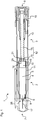
- FIGs. 2 and 3 show perspective views of a part of the piston rod body 19.
- the piston rod body 19 has a longitudinal axis 29 and comprises a main body part 22, a connecting portion 23 and a head 24.
- the piston rod body 19 may be a lead screw.
- the main body part 22 of the piston rod body comprises a thread 25.
- the thread 25 of the main body part 22 is helical.
- An interaction of the thread 25 with parts of a drive mechanism 3 enables the piston rod body to rotate and/or to move axially.
- the main body part 22 of the piston rod body 19 comprises a linear groove 26 in axial direction. The linear groove 26 allows for interaction with a drive member.
- the piston rod body 19 comprises a connecting portion 23, being connected to a proximal end side 27 of the main body part 22.
- the connecting portion 23 has a circular cross-section.
- the radial width of the connecting portion 23 is smaller than a minimum radial width of the main body part 22, seen in a cross-section perpendicular to the longitudinal axis 29.
- the piston rod body 19 comprises a head 24.
- the distal end 30 of the head is connected to the proximal end 31 of the connecting portion 23.
- the head 24 comprises four sidewalls 32-35, wherein the first and the second sidewall 32, 33 are opposite to each other and have in radial direction a minimum width. Further, the third and fourth sidewall 34, 35 are also opposite to each other and have in radial direction a maximum width.
- the head 24 comprises a main section 36 wherein the radial width between the sidewalls 32-35 is constant, and a front section 37 wherein the radial width between the sidewalls 32-35 reduces.
- edges connecting to adjacent sidewalls of the head 24, e.g. the first and the third sidewall 32, 34, are curved.
- the first and the second sidewalls 32, 33 have a minimum radial width of the head 24.
- a principal direction 38 of the head 24 is defined being perpendicular to a direction being defined by the minimal width.
- the principal direction 38 of the head 24 is defined by being perpendicular to a connecting line of the first and the second sidewall 32, 33.
- the minimum radial width of the head 24 is bigger than the diameter of the connecting portion 23.
- the third and the fourth sidewall 34, 35 have a curved shape.
- FIGs. 4 and 5 show perspective views of a bearing 18.
- the bearing 18 comprises a first surface 39, a second surface 20 and third surface 40.
- the first surface 39 of the bearing 18 may be a fixing proximal end wall.
- the fixing proximal end wall may fix the bearing 18 to a piston rod body 19.
- the second surface 20 of the bearing 18 may be a bung contact wall or a distal end wall 20.
- the bung contact wall of the bearing 18 may be in direct contact to a bung 10.
- the distal end wall 20 of the bearing 18 may be arranged to abut a proximal end face of the bung.
- the third surface 40 of the bearing 18 may be a sidewall.
- the sidewall 40 may be perpendicular to the first surface 39 and to the second surface 20.
- the bearing 18 has an axis 46.
- the first surface 39 and the second surface 20 are spaced apart in the direction of the axis 46.
- the third surface 40 connects the first and the second surface 39, 20.
- the first surface 39 has a C-shaped cross-section.
- An opening 41 is provided in the first surface 39. Seen towards the longitudinal axis 29, the opening 41 has a constant width which is also the maximum width of the opening 41, and in the rear part the width of the opening 41 reduces.
- the maximum width of the opening 41 provided in the first surface 39 is smaller than the minimum radial width of the head 24 in the main section 36 of the head 24. Further, the maximum width of the opening 41 provided in the first surface 39 is equal to or wider than the diameter of the radial width of the connecting portion 23. Thereby, the opening 41 provided in the first surface 39 allows insertion of the connecting portion 23 of the piston rod body 19 into the first surface 39. However, as the opening 41 provided in the first surface 39 is smaller than the minimum radial width of the head 24, an axial movement of the piston rod body 19 relative to the bearing 18 is prevented.
- the third surface 40 Seen in a cross-section perpendicular to the longitudinal axis 29, the third surface 40 has a C-shaped cross-section.
- An opening 42 is provided in the third surface 40.
- the third surface 40 defines an entry area 43 and a rotational space 44. Seen towards the longitudinal axis 29, the width of the opening 42 provided in the third surface 40 reduces until a minimum width, e.g. until a point of minimum width.
- the area of reducing width of the opening 42 provided in the third surface 40 is the entry area 43.
- the third surface 40 defines the rotational space 44 inside the opening 42. In the rotational space 44, the opening 42 provided in the third surface 40 is circular.
- the diameter of the opening 42 in the rotational space 44 is bigger than the maximum radial width of the head 24.
- the minimum width is chosen such that this width is equal to or bigger than the minimum radial width of the head 24 and smaller than the maximum radial width of the head 24.
- protrusions 45 are provided on the sidewall 40.
- the protrusions 45 may be flexible.
- the protrusions 45 may be shaped to allow a movement of an element into a direction towards the longitudinal axis 29 and further to restrain a movement away from the longitudinal axis 29.
- FIGs. 6-11 show an assembly of the bearing 18 and the piston rod body 19.
- FIGs. 6 , 8 , and 10 show the assembly in a perspective view.
- FIGs. 7 , 9 , and 11 show the assembly in a cross-section taken perpendicular to the longitudinal axis 29.
- FIGs. 6 and 7 show the bearing 18 and the piston rod body 19 in an unassembled state.
- the bearing 18 and the piston rod body 19 are aligned such that the axis 46 of the bearing 18 is perpendicular to the longitudinal axis 29 of the piston rod body 19. Further, they are mounted by a movement wherein the bearing 18 is moved towards the piston rod body 19 and the two axes 46, 29 are kept parallel to each other. In other words, the bearing 18 is mounted to the piston rod body 19 by a lateral movement.
- the bearing 18 needs to be aligned to the piston rod body 19 to mount it to the piston rod body 19.
- a mounting is only possible if the principal direction 38 of the head 24 of the piston rod body 19 is aligned towards the opening 42 provided in the third surface 40 of the bearing 18.
- an insertion slant 47 is defined as the width of the opening 42 provided in the third surface 40 reduces towards the longitudinal axis 29 until a minimum width.
- the insertion slant 47 allows for a manufacturing of the bearing 18 to the piston rod body 19 if they are disaligned by a few degrees, e.g. by not more than 20 degrees.
- the width of the opening 42 provided in the third surface 40 reduces towards the longitudinal axis 29 with an increasing degree until a minimum width.
- the insertion slant 47 is shaped convex, allowing for a smooth interaction of the head 24 and the insertion slant 47.
- the curved edges of the head 24 may slide along the convex surface of the insertion slant 47, thereby enabling an assembly of the head 24 and the bearing 18 even if the axis 46 of the bearing 18 and the longitudinal axis 29 of the piston rod body 19 are slightly misaligned.
- FIGs. 8 and 9 show the bearing 18 and the piston rod body 19 during the assembling step.
- FIGs. 10 and 11 shows a bearing 18 mounted to the piston rod body 19.
- the head 24 is positioned in the rotational space 44 of the third surface 40.
- the head 24 is enabled to rotate relative to the bearing 18 inside the rotational space 44 as the diameter of the opening 42 in the rotational space 44 is bigger than the maximum radial width of the head 24.
- the protrusions 45 in the entry area 43 of the opening 42 provided in the third surface 40 prevent the head 24 from accidentally moving out of the rotational space 44.
- the bearing 18 is prevented from an axial movement relative to the piston rod body 19.
- the maximum width of the opening 41 provided in the first surface 39 being smaller than the minimum radial width of the head 24 prevents the axial movement.
- FIG. 12 shows a bearing 18 assembled to a piston rod body 19 in a cross-sectional view taken along the longitudinal axis 29. It can be gathered from FIG. 12 that the maximum width of the opening 41 provided in the first surface 39 being smaller than the minimum radial width of the head 24 prevents the axial movement.
- FIGs. 13A-13C show cross-sectional views of the bearing 18 and the piston rod body 19 in a cross-section perpendicular to the longitudinal axis 29. It can be gathered from FIGs. 13A-13C that the head 24 and the piston rod body 19 are enabled to rotate relative to the bearing 18. This is enabled by the rotational space 44 having a width that is wider than the maximum radial width of the head 24.
- FIG. 14 shows parts of a drug delivery device 1 in a perspective view.
- a drug delivery device 1 wherein a cartridge holder is removed, e.g. to exchange the cartridge holder, is shown.
- the bearing 18 is fixed to the piston rod body 19 in a way that it cannot be knocked off accidentally by a user, the safety and reusability of the device is improved.
Landscapes
- Health & Medical Sciences (AREA)
- Vascular Medicine (AREA)
- Engineering & Computer Science (AREA)
- Anesthesiology (AREA)
- Biomedical Technology (AREA)
- Heart & Thoracic Surgery (AREA)
- Hematology (AREA)
- Life Sciences & Earth Sciences (AREA)
- Animal Behavior & Ethology (AREA)
- General Health & Medical Sciences (AREA)
- Public Health (AREA)
- Veterinary Medicine (AREA)
- Infusion, Injection, And Reservoir Apparatuses (AREA)
Claims (15)
- Medikamenten-Verabreichungsvorrichtung (1), bei der es sich um einen stiftartigen Injektor auf Nadelbasis handelt, wobei die Medikamenten-Verabreichungsvorrichtung Folgendes aufweist:- eine Kartuscheneinheit (2), wobei die Kartuscheneinheit (2) ein Kartuschenhalteglied (11) aufweist, wobei das Kartuschenhalteglied (11) dazu vorgesehen ist, eine Kartusche (4) darin zu halten, wobei die Kartusche (4) einen Auslass (6) an ihrem distalen Ende hat, wobei Medikament (5) in der Kartusche (4) gehalten wird und ein Stopfen (10) in der Kartusche (4) gehalten wird, wobei der Stopfen (10) bezüglich der Kartusche (4) beweglich ist, wobei eine Bewegung des Stopfens (10) bezüglich der Kartusche (4) in eine distale Richtung veranlasst, dass während des Betriebs der Medikamenten-Verabreichungsvorrichtung (1) Medikament (5) durch den Auslass (6) der Kartusche (4) aus der Kartusche (4) abgegeben wird, und- einen Antriebsmechanismus (3), wobei der Antriebsmechanismus (3) ein Gehäuse (13) und eine Kolbenstangenanordnung (12) aufweist, wobei die Kolbenstangenanordnung (12) in dem Gehäuse (13) gehalten wird, wobei die Kolbenstangenanordnung (12) ein Lager (18) und einen Kolbenstangenkörper (19) aufweist, wobei das Lager (18) axial an dem Kolbenstangenkörper (19) fixiert ist und der Kolbenstangenkörper (19) in der Lage ist, sich relativ zu dem Lager (18) zu drehen, wobei das Lager (18) eine Achse (46) hat und eine erste und eine zweite Fläche (39, 20) aufweist, die in der Richtung der Achse (46) beabstandet sind, und wobei das Lager eine dritte Fläche (40) aufweist, wobei die dritte Fläche (40) die erste und die zweite Fläche (39, 20) verbindet, wobei
die Kartuscheneinheit (2) und der Antriebsmechanismus (3) lösbar aneinander befestigt sind, wobei das Kartuschenhalteglied (11) mit einem Fixierungsglied versehen ist, um die Kartuscheneinheit (2) an dem Antriebsmechanismus (3) anzubringen, und wobei eine proximale Endseite (14) der Kartuscheneinheit (2) an einer distalen Endseite (15) des Gehäuses (13) an dem Antriebsmechanismus (3) befestigt ist, wobei
die Kolbenstangenanordnung (12) zum Übertragen von Kraft an den Stopfen (10) ausgestaltet ist, wodurch der Stopfen bezüglich der Kartusche (4) in die distale Richtung verlagert wird, um eine Dosis Medikament (5) aus der Kartusche (4) abzugeben, wobei eine Öffnung (41, 42) jeweils in der ersten und der dritten Fläche (39, 40) vorgesehen ist, und wobei die Öffnung (41) in der ersten Fläche (39) mit der Öffnung (42) in der dritten Fläche (40) verbunden ist, und wobei die zweite Fläche (20) des Lagers (18) durch eine Stopfenkontaktwand gebildet wird, die zum Anliegen an einer proximalen Endfläche des Stopfens (10) angeordnet ist. - Medikamenten-Verabreichungsvorrichtung nach dem gegenwärtigen Anspruch 1,
wobei die dritte Fläche (40) einen Eintrittsbereich (43) definiert, wobei die in der dritten Fläche (40) vorgesehene Öffnung (42) eine Mindestbreite hat. - Medikamenten-Verabreichungsvorrichtung nach dem gegenwärtigen Anspruch 2,
wobei die in der ersten Fläche (39) vorgesehene Öffnung (41) eine Höchstbreite hat, die kleiner als die Mindestbreite der in der dritten Fläche (40) vorgesehenen Öffnung (42) ist. - Medikamenten-Verabreichungsvorrichtung nach einem der Ansprüche 2 oder 3,
wobei die Breite der in der dritten Fläche (40) vorgesehenen Öffnung (42) im Eintrittsbereich (43) in der radialen Richtung zu der Achse (46) hin abnimmt, bis die Mindestbreite erreicht ist. - Medikamenten-Verabreichungsvorrichtung nach einem der Ansprüche 2 bis 4,
wobei die Breite der in der dritten Fläche (40) vorgesehenen Öffnung (42) in einem senkrecht zu der Achse (46) verlaufenden Querschnitt gesehen und in radialer Richtung zu der Achse (46) hin von der Mindestbreite aus zunimmt, wodurch die dritte Fläche (40) einen Rotationsraum (44) in der dritten Fläche (40) definiert, wobei die Breite des Rotationsraums (44) größer als die Mindestbreite ist. - Medikamenten-Verabreichungsvorrichtung nach einem der vorhergehenden Ansprüche,
wobei flexible Elemente (45) auf der dritten Fläche (40) vorgesehen sind und die flexiblen Elemente (45) in die in der dritten Fläche (40) vorgesehene Öffnung (42) vorragen. - Medikamenten-Verabreichungsvorrichtung nach einem der vorhergehenden Ansprüche,
wobei die dritte Fläche (40) in einer senkrecht zu der Achse (46) verlaufenden Ebene gesehen einen C-förmigen Querschnitt hat. - Medikamenten-Verabreichungsvorrichtung nach einem der vorhergehenden Ansprüche,
wobei die erste Fläche (39) in einer senkrecht zu der Achse (46) verlaufenden Ebene gesehen einen C-förmigen Querschnitt hat. - Medikamenten-Verabreichungsvorrichtung nach einem der vorhergehenden Ansprüche,
wobei der Kolbenstangenkörper (19) eine Längsachse (29) hat und wobei das Lager (18) durch eine Bewegung des Lagers (18) und des Kolbenstangenkörpers (19) aufeinander zu an den Kolbenstangenkörper (19) montierbar ist, wobei die Achse (46) des Lagers (18) und die Längsachse (29) des Kolbenstangenkörpers (19) während der Bewegung parallel zueinander ausgerichtet sind. - Medikamenten-Verabreichungsvorrichtung nach Anspruch 9,
wobei der Kolbenstangenkörper (19) einen Kopf (24) aufweist, wobei die radiale Breite des Kopfs (24) entlang der Azimutrichtung um die Längsachse (29) herum variiert und
wobei der Kopf (24) eine radiale Mindestbreite, eine radiale Höchstbreite und eine Hauptrichtung (38) aufweist, die senkrecht zu einer von der radialen Mindestbreite definierten Richtung verläuft. - Medikamenten-Verabreichungsvorrichtung nach Anspruch 10, wobei der Kopf (24) ein Anordnen des Lagers (18) an dem Kolbenstangenkörper (19) nur ermöglicht, wenn die in der ersten und der dritten Fläche (39, 40) vorgesehene Öffnung (41, 42) und die Hauptrichtung (38) des Kopfs (24) fluchten.
- Medikamenten-Verabreichungsvorrichtung nach Anspruch 10 oder 11,
wobei der Rotationsraum (44) der dritten Fläche (40) des Lagers (18) breiter als die radiale Höchstbreite des Kopfs (24) ist, wodurch sich der Kopf (24) in dem Rotationsraum (44) drehen kann. - Medikamenten-Verabreichungsvorrichtung nach einem der Ansprüche 10 bis 12,
wobei die Mindestbreite des Eintrittsbereichs (43) in der in der dritten Fläche (40) vorgesehenen Öffnung (42) gleich der oder größer als die radiale Mindestbreite des Kopfs (24) ist
und
wobei die Mindestbreite des Eintrittsbereichs (43) in der in der dritten Fläche (40) vorgesehenen Öffnung (42) kleiner als die radiale Höchstbreite des Kopfs (24) ist. - Medikamenten-Verabreichungsvorrichtung nach einem der Ansprüche 10 bis 13,
wobei der Kolbenstangenkörper (19) ferner einen Hauptkörperteil (22) und einen Verbindungsabschnitt (23) aufweist, der den Kopf (24) mit dem Hauptkörperteil (22) verbindet, wobei der Verbindungsabschnitt (23) einen Durchmesser hat, der, in einem senkrecht zu der Längsachse (29) verlaufenden Querschnitt gesehen, kleiner als die radiale Mindestbreite des Kopfs (24) ist. - Medikamenten-Verabreichungsvorrichtung nach Anspruch 14, wobei die Höchstbreite der in der ersten Fläche (39) vorgesehenen Öffnung (41) gleich dem oder größer als der Höchstdurchmesser des Verbindungsabschnitts (23) und kleiner als die radiale Mindestbreite des Kopfs (24) ist.
Priority Applications (3)
| Application Number | Priority Date | Filing Date | Title |
|---|---|---|---|
| DK19205851.9T DK3622988T3 (da) | 2012-05-30 | 2013-05-28 | Stempelstangsindretning og lægemiddeladministrationsanordning, der omfatter en sådan stempelstangsindretning |
| EP19205851.9A EP3622988B1 (de) | 2012-05-30 | 2013-05-28 | Kolbenstangenanordnung und arzneimittelabgabevorrichtung mit einer solchen kolbenstangenanordnung |
| EP13726724.1A EP2854909B1 (de) | 2012-05-30 | 2013-05-28 | Lager für einen kolbenstangenkörper für eine arzneimittelabgabevorrichtung, kolbenstangenanordnung und kolbenstangenkörper |
Applications Claiming Priority (3)
| Application Number | Priority Date | Filing Date | Title |
|---|---|---|---|
| EP12170069 | 2012-05-30 | ||
| EP13726724.1A EP2854909B1 (de) | 2012-05-30 | 2013-05-28 | Lager für einen kolbenstangenkörper für eine arzneimittelabgabevorrichtung, kolbenstangenanordnung und kolbenstangenkörper |
| PCT/EP2013/060912 WO2013178600A1 (en) | 2012-05-30 | 2013-05-28 | Bearing for a piston rod body for a drug delivery device, a piston rod arrangement and a piston rod body |
Related Child Applications (2)
| Application Number | Title | Priority Date | Filing Date |
|---|---|---|---|
| EP19205851.9A Division-Into EP3622988B1 (de) | 2012-05-30 | 2013-05-28 | Kolbenstangenanordnung und arzneimittelabgabevorrichtung mit einer solchen kolbenstangenanordnung |
| EP19205851.9A Division EP3622988B1 (de) | 2012-05-30 | 2013-05-28 | Kolbenstangenanordnung und arzneimittelabgabevorrichtung mit einer solchen kolbenstangenanordnung |
Publications (2)
| Publication Number | Publication Date |
|---|---|
| EP2854909A1 EP2854909A1 (de) | 2015-04-08 |
| EP2854909B1 true EP2854909B1 (de) | 2020-07-15 |
Family
ID=48576378
Family Applications (2)
| Application Number | Title | Priority Date | Filing Date |
|---|---|---|---|
| EP19205851.9A Active EP3622988B1 (de) | 2012-05-30 | 2013-05-28 | Kolbenstangenanordnung und arzneimittelabgabevorrichtung mit einer solchen kolbenstangenanordnung |
| EP13726724.1A Revoked EP2854909B1 (de) | 2012-05-30 | 2013-05-28 | Lager für einen kolbenstangenkörper für eine arzneimittelabgabevorrichtung, kolbenstangenanordnung und kolbenstangenkörper |
Family Applications Before (1)
| Application Number | Title | Priority Date | Filing Date |
|---|---|---|---|
| EP19205851.9A Active EP3622988B1 (de) | 2012-05-30 | 2013-05-28 | Kolbenstangenanordnung und arzneimittelabgabevorrichtung mit einer solchen kolbenstangenanordnung |
Country Status (7)
| Country | Link |
|---|---|
| US (3) | US10046118B2 (de) |
| EP (2) | EP3622988B1 (de) |
| JP (2) | JP2015517858A (de) |
| CN (2) | CN104349808A (de) |
| DK (1) | DK3622988T3 (de) |
| HK (1) | HK1203864A1 (de) |
| WO (1) | WO2013178600A1 (de) |
Families Citing this family (7)
| Publication number | Priority date | Publication date | Assignee | Title |
|---|---|---|---|---|
| TWI637762B (zh) | 2016-06-23 | 2018-10-11 | 卡貝歐洲有限公司 | 藥物輸送裝置 |
| PL3399214T3 (pl) * | 2017-05-05 | 2021-01-25 | Eppendorf Ag | Elektroniczny napęd dozujący |
| EP3399215B1 (de) * | 2017-05-05 | 2020-07-08 | Eppendorf AG | Spindelantrieb |
| EP3598990A1 (de) * | 2018-07-23 | 2020-01-29 | Sanofi | Wirkstoffabgabevorrichtung und anordnungsverfahren für eine wirkstoffabgabevorrichtung |
| CN113195867A (zh) | 2018-12-17 | 2021-07-30 | 沙特阿拉伯石油公司 | 井设备的基于图像的检查及自动化库存和供应链管理 |
| US11624265B1 (en) | 2021-11-12 | 2023-04-11 | Saudi Arabian Oil Company | Cutting pipes in wellbores using downhole autonomous jet cutting tools |
| US11867012B2 (en) | 2021-12-06 | 2024-01-09 | Saudi Arabian Oil Company | Gauge cutter and sampler apparatus |
Citations (5)
| Publication number | Priority date | Publication date | Assignee | Title |
|---|---|---|---|---|
| CN201324413Y (zh) | 2008-07-09 | 2009-10-14 | 邓源基 | 定量可调笔式注射器 |
| WO2011154490A1 (en) | 2010-06-11 | 2011-12-15 | Sanofi-Aventis Deutschland Gmbh | Drive mechanism for a drug delivery device |
| WO2011154486A1 (en) | 2010-06-11 | 2011-12-15 | Sanofi-Aventis Deutschland Gmbh | Drive mechanism for a drug delivery device and drug delivery device |
| WO2011154482A2 (en) | 2010-06-11 | 2011-12-15 | Sanofi-Aventis Deutschland Gmbh | Assembly for a drug delivery device and drug delivery device |
| CH703993A2 (de) | 2012-02-09 | 2012-03-15 | Tecpharma Licensing Ag | Injektionsgerät zur Verabreichung oder Förderung von fluidem Produkt. |
Family Cites Families (73)
| Publication number | Priority date | Publication date | Assignee | Title |
|---|---|---|---|---|
| US533575A (en) | 1895-02-05 | wilkens | ||
| NZ202544A (en) | 1981-11-18 | 1985-02-28 | D & S Mfg Pty Ltd | Food coatings, fillers or pellets;ingredients having a moisture content of 8-14 percent extruded |
| ATE51525T1 (de) * | 1984-06-06 | 1990-04-15 | Medrad Inc | Angiographie-injektor und mit diesem verwendbare angiograhie-spritze. |
| DE3715258C2 (de) | 1987-05-08 | 1996-10-31 | Haselmeier Wilhelm Fa | Injektionsgerät |
| GB8713810D0 (en) | 1987-06-12 | 1987-07-15 | Hypoguard Uk Ltd | Measured dose dispensing device |
| ATE76762T1 (de) * | 1987-11-25 | 1992-06-15 | Gudmar Olovson | Spritze. |
| US5007904A (en) * | 1989-01-19 | 1991-04-16 | Coeur Laboratories, Inc. | Plunger for power injector angiographic syringe, and syringe comprising same |
| US4911695A (en) * | 1989-04-03 | 1990-03-27 | Coeur Laboratories, Inc. | Plunger for power-driven angiographic syringe, and syringe and power injector system utilizing same |
| US4911965A (en) | 1989-05-22 | 1990-03-27 | General Electric Co. | Assembly for protecting decorative surface |
| US5226895A (en) | 1989-06-05 | 1993-07-13 | Eli Lilly And Company | Multiple dose injection pen |
| US5226896A (en) | 1990-04-04 | 1993-07-13 | Eli Lilly And Company | Dose indicating injection pen |
| AU641206B2 (en) | 1991-01-22 | 1993-09-16 | Eli Lilly And Company | Multiple dose injection pen |
| DK175491D0 (da) | 1991-10-18 | 1991-10-18 | Novo Nordisk As | Apparat |
| US5279586A (en) | 1992-02-04 | 1994-01-18 | Becton, Dickinson And Company | Reusable medication delivery pen |
| US5271527A (en) | 1992-04-02 | 1993-12-21 | Habley Medical Technology Corporation | Reusable pharmaceutical dispenser with full stroke indicator |
| US5300041A (en) | 1992-06-01 | 1994-04-05 | Habley Medical Technology Corporation | Dose setting and repeating syringe |
| US5391157A (en) | 1992-10-20 | 1995-02-21 | Eli Lilly And Company | End of dose indicator |
| US5378233A (en) | 1992-11-18 | 1995-01-03 | Habley Medical Technology Corporation | Selected dose pharmaceutical dispenser |
| US5320609A (en) | 1992-12-07 | 1994-06-14 | Habley Medical Technology Corporation | Automatic pharmaceutical dispensing syringe |
| FR2701211B1 (fr) | 1993-02-08 | 1995-05-24 | Aguettant Lab | Instrument doseur, notamment d'injection |
| US5383865A (en) | 1993-03-15 | 1995-01-24 | Eli Lilly And Company | Medication dispensing device |
| ZA941881B (en) | 1993-04-02 | 1995-09-18 | Lilly Co Eli | Manifold medication injection apparatus and method |
| US5582598A (en) | 1994-09-19 | 1996-12-10 | Becton Dickinson And Company | Medication delivery pen with variable increment dose scale |
| CA2213682C (en) | 1995-03-07 | 2009-10-06 | Eli Lilly And Company | Recyclable medication dispensing device |
| JPH09118077A (ja) | 1995-08-22 | 1997-05-06 | Ricoh Co Ltd | 可逆性感熱記録媒体 |
| AU1860697A (en) | 1995-09-08 | 1997-07-28 | Visionary Medical Products Corporation | Pen-type injector drive mechanism |
| US5674204A (en) | 1995-09-19 | 1997-10-07 | Becton Dickinson And Company | Medication delivery pen cap actuated dose delivery clutch |
| US5688251A (en) | 1995-09-19 | 1997-11-18 | Becton Dickinson And Company | Cartridge loading and priming mechanism for a pen injector |
| US5851079A (en) | 1996-10-25 | 1998-12-22 | The Procter & Gamble Company | Simplified undirectional twist-up dispensing device with incremental dosing |
| DE19730999C1 (de) | 1997-07-18 | 1998-12-10 | Disetronic Licensing Ag | Dosierknopfsicherung an einer Vorrichtung zur dosierten Verabreichung eines injizierbaren Produkts |
| US5921966A (en) | 1997-08-11 | 1999-07-13 | Becton Dickinson And Company | Medication delivery pen having an improved clutch assembly |
| EP1003581B1 (de) * | 1998-01-30 | 2000-11-08 | Novo Nordisk A/S | Eine injektionsspritze |
| US6221053B1 (en) | 1998-02-20 | 2001-04-24 | Becton, Dickinson And Company | Multi-featured medication delivery pen |
| US6096010A (en) | 1998-02-20 | 2000-08-01 | Becton, Dickinson And Company | Repeat-dose medication delivery pen |
| US6248095B1 (en) | 1998-02-23 | 2001-06-19 | Becton, Dickinson And Company | Low-cost medication delivery pen |
| US6186233B1 (en) | 1998-11-30 | 2001-02-13 | Weatherford Lamb, Inc. | Down hole assembly and method for forming a down hole window and at least one keyway in communication with the down hole window for use in multilateral wells |
| DE19900827C1 (de) | 1999-01-12 | 2000-08-17 | Disetronic Licensing Ag | Vorrichtung zur dosierten Verabreichung eines injizierbaren Produkts |
| DE19900792C1 (de) | 1999-01-12 | 2000-06-15 | Disetronic Licensing Ag | Vorrichtung zur Verabreichung eines injizierbaren Produkts |
| DE29900482U1 (de) | 1999-01-14 | 2000-08-31 | Medico Dev Investment Co | Injektionsgerät |
| SE9901366D0 (sv) | 1999-04-16 | 1999-04-16 | Pharmacia & Upjohn Ab | Injector device and method for its operation |
| EP1218042B1 (de) | 1999-08-05 | 2006-02-22 | Becton Dickinson and Company | Stiftförmige medikamentenabgabevorrichtung |
| JP3313671B2 (ja) | 1999-08-12 | 2002-08-12 | 日本電気株式会社 | デジタル制御型発振回路 |
| US6253804B1 (en) * | 1999-11-05 | 2001-07-03 | Minimed Inc. | Needle safe transfer guard |
| GB0007071D0 (en) | 2000-03-24 | 2000-05-17 | Sams Bernard | One-way clutch mechanisms and injector devices |
| US6663602B2 (en) | 2000-06-16 | 2003-12-16 | Novo Nordisk A/S | Injection device |
| WO2002007812A2 (en) * | 2000-07-20 | 2002-01-31 | Acist Medical Systems, Inc. | Syringe plunger locking mechanism |
| ATE335519T1 (de) | 2000-10-09 | 2006-09-15 | Lilly Co Eli | Stiftvorrichtung zur verabreichung des parathyroid-hormons |
| US6899699B2 (en) | 2001-01-05 | 2005-05-31 | Novo Nordisk A/S | Automatic injection device with reset feature |
| EP2275158B1 (de) | 2001-05-16 | 2013-01-23 | Eli Lilly and Company | Spritzvorrichtung |
| JP4350525B2 (ja) | 2002-03-18 | 2009-10-21 | イーライ リリー アンド カンパニー | 機械的利点を与えるギヤーセット付き薬剤分与装置 |
| ES2270096T3 (es) | 2002-10-01 | 2007-04-01 | Becton Dickinson And Company | Lapiz de suministro de medicacion. |
| US20050015057A1 (en) | 2002-11-28 | 2005-01-20 | Soren Steenfeldt-Jensen | Cylindrical piston press foot |
| FR2850283B1 (fr) | 2003-01-28 | 2005-12-16 | Sedat | Dispositif de support de seringue angiographique et ses combinaisons avec une seringue angiographique et avec un injecteur angiographique |
| GB0304822D0 (en) | 2003-03-03 | 2003-04-09 | Dca Internat Ltd | Improvements in and relating to a pen-type injector |
| GB0304823D0 (en) | 2003-03-03 | 2003-04-09 | Dca Internat Ltd | Improvements in and relating to a pen-type injector |
| US6932794B2 (en) | 2003-04-03 | 2005-08-23 | Becton, Dickinson And Company | Medication delivery pen |
| KR101121317B1 (ko) | 2003-08-12 | 2012-03-09 | 일라이 릴리 앤드 캄파니 | 기계적 확대율을 갖는 삼중 나사식 쓰레드를 갖는 약제투여 장치 |
| EP1541185A1 (de) | 2003-12-08 | 2005-06-15 | Novo Nordisk A/S | Automatische Spritze mit Vorfüllmechanismus |
| DE102004063647A1 (de) | 2004-12-31 | 2006-07-20 | Tecpharma Licensing Ag | Vorrichtung zur dosierten Verabreichung eines fluiden Produkts mit Kupplung |
| WO2006084876A1 (en) | 2005-02-11 | 2006-08-17 | Novo Nordisk A/S | Injection device |
| US20060184103A1 (en) | 2005-02-17 | 2006-08-17 | West Pharmaceutical Services, Inc. | Syringe safety device |
| US8038656B2 (en) * | 2006-09-29 | 2011-10-18 | Tyco Healthcare Group Lp | Detachable plunger rod syringe |
| EP1923084A1 (de) * | 2006-11-17 | 2008-05-21 | Sanofi-Aventis Deutschland GmbH | Dosier- und Antriebsvorrichtung für Medikamentenabgabegeräte |
| US8647309B2 (en) | 2008-05-02 | 2014-02-11 | Sanofi-Aventis Deutschland Gmbh | Medication delivery device |
| US8840591B2 (en) | 2008-12-12 | 2014-09-23 | Sanofi-Aventis Deutschland Gmbh | Drive mechanism for a medication delivery device and medication delivery device |
| US9089652B2 (en) * | 2008-12-12 | 2015-07-28 | Sanofi-Aventis Deutschland Gmbh | Drive mechanism for a medication delivery device and medication delivery device |
| US9108007B2 (en) | 2009-06-01 | 2015-08-18 | Sanofi-Aventis Deutschland Gmbh | Spindle and bearing combination and drug delivery device |
| KR101027514B1 (ko) | 2009-06-15 | 2011-04-06 | 삼성전기주식회사 | 입력 장치 |
| CA2766001A1 (en) | 2009-07-15 | 2011-01-20 | Sanofi-Aventis Deutschland Gmbh | Thrust bearing assembly, drive train, and medicament delivery device |
| EP2579925B1 (de) | 2010-06-11 | 2018-03-21 | Sanofi-Aventis Deutschland GmbH | Arzneimittelabgabevorrichtung |
| US8304152B2 (en) | 2010-07-29 | 2012-11-06 | Xerox Corporation | Spirodilactam polycarbonate containing photoconductors |
| WO2012017035A1 (en) * | 2010-08-06 | 2012-02-09 | Sanofi-Aventis Deutschland Gmbh | Cartridge holder and method for assembling a cartridge unit for a drug delivery device |
| EP2438951A1 (de) * | 2010-10-06 | 2012-04-11 | Sanofi-Aventis Deutschland GmbH | Antriebsmechanismus für eine Arzneimittelabgabevorrichtung und Arzneimittelabgabevorrichtung |
-
2013
- 2013-05-28 EP EP19205851.9A patent/EP3622988B1/de active Active
- 2013-05-28 EP EP13726724.1A patent/EP2854909B1/de not_active Revoked
- 2013-05-28 US US14/402,299 patent/US10046118B2/en active Active
- 2013-05-28 DK DK19205851.9T patent/DK3622988T3/da active
- 2013-05-28 JP JP2015514454A patent/JP2015517858A/ja active Pending
- 2013-05-28 WO PCT/EP2013/060912 patent/WO2013178600A1/en active Application Filing
- 2013-05-28 CN CN201380026655.XA patent/CN104349808A/zh active Pending
- 2013-05-28 CN CN201810350380.XA patent/CN108815645A/zh active Pending
-
2015
- 2015-05-18 HK HK15104689.1A patent/HK1203864A1/xx unknown
-
2018
- 2018-05-16 JP JP2018094192A patent/JP6584582B2/ja active Active
- 2018-08-13 US US16/102,149 patent/US10744267B2/en active Active
-
2020
- 2020-06-30 US US16/916,886 patent/US11612696B2/en active Active
Patent Citations (5)
| Publication number | Priority date | Publication date | Assignee | Title |
|---|---|---|---|---|
| CN201324413Y (zh) | 2008-07-09 | 2009-10-14 | 邓源基 | 定量可调笔式注射器 |
| WO2011154490A1 (en) | 2010-06-11 | 2011-12-15 | Sanofi-Aventis Deutschland Gmbh | Drive mechanism for a drug delivery device |
| WO2011154486A1 (en) | 2010-06-11 | 2011-12-15 | Sanofi-Aventis Deutschland Gmbh | Drive mechanism for a drug delivery device and drug delivery device |
| WO2011154482A2 (en) | 2010-06-11 | 2011-12-15 | Sanofi-Aventis Deutschland Gmbh | Assembly for a drug delivery device and drug delivery device |
| CH703993A2 (de) | 2012-02-09 | 2012-03-15 | Tecpharma Licensing Ag | Injektionsgerät zur Verabreichung oder Förderung von fluidem Produkt. |
Also Published As
| Publication number | Publication date |
|---|---|
| US11612696B2 (en) | 2023-03-28 |
| US10046118B2 (en) | 2018-08-14 |
| JP2018149335A (ja) | 2018-09-27 |
| CN104349808A (zh) | 2015-02-11 |
| EP2854909A1 (de) | 2015-04-08 |
| WO2013178600A1 (en) | 2013-12-05 |
| EP3622988A1 (de) | 2020-03-18 |
| JP6584582B2 (ja) | 2019-10-02 |
| US10744267B2 (en) | 2020-08-18 |
| US20190009033A1 (en) | 2019-01-10 |
| US20150133874A1 (en) | 2015-05-14 |
| HK1203864A1 (en) | 2015-11-06 |
| JP2015517858A (ja) | 2015-06-25 |
| DK3622988T3 (da) | 2023-03-06 |
| US20200324053A1 (en) | 2020-10-15 |
| CN108815645A (zh) | 2018-11-16 |
| EP3622988B1 (de) | 2022-12-14 |
Similar Documents
| Publication | Publication Date | Title |
|---|---|---|
| US11612696B2 (en) | Bearing for a piston rod body for a drug delivery device, a piston rod arrangement and a piston rod body | |
| EP2637723B1 (de) | Ansteuerungsmechanismus für eine wirkstofffreisetzungsvorrichtung und wirkstofffreisetzungsvorrichtung | |
| EP2854908B1 (de) | Antriebsmechanismus für eine arzneimittelabgabevorrichtung und arzneimittelabgabevorrichtung | |
| EP2739256B1 (de) | Wirkstofffreisetzungsvorrichtung und daran anzuschliessende kartusche | |
| EP2704777B1 (de) | Wirkstofffreisetzungsvorrichtung und kartuschenhalterung für eine wirkstofffreisetzungsvorrichtung | |
| EP2895218B1 (de) | Antriebsmechanismus für eine arzneimittelabgabevorrichtung und arzneimittelabgabevorrichtung | |
| EP2854907B1 (de) | Antriebsmechanismus für eine arzneimittelabgabevorrichtung und arzneimittelabgabevorrichtung | |
| WO2013139894A1 (en) | Housing of a drug delivery device | |
| EP2579929B1 (de) | Antriebsmechanismus für eine Arzneimittelabgabevorrichtung und Arzneimittelabgabevorrichtung | |
| US9597457B2 (en) | Piston rod for a drug delivery device and drug delivery device comprising a piston rod | |
| US20160193419A1 (en) | Drug Delivery Device | |
| EP2830682B1 (de) | Gehäuse einer wirkstofffreisetzungsvorrichtung | |
| EP2957308A1 (de) | Kassettenhalter für eine Arzneimittelausgabevorrichtung | |
| US20180243512A1 (en) | Injection Device | |
| US10596325B2 (en) | Pen-type drug injection device with iris style quick coupling for piston rod resetting | |
| AU2012292240B9 (en) | Drug delivery device and cartridge to be interconnected therewith |
Legal Events
| Date | Code | Title | Description |
|---|---|---|---|
| PUAI | Public reference made under article 153(3) epc to a published international application that has entered the european phase |
Free format text: ORIGINAL CODE: 0009012 |
|
| 17P | Request for examination filed |
Effective date: 20150105 |
|
| AK | Designated contracting states |
Kind code of ref document: A1 Designated state(s): AL AT BE BG CH CY CZ DE DK EE ES FI FR GB GR HR HU IE IS IT LI LT LU LV MC MK MT NL NO PL PT RO RS SE SI SK SM TR |
|
| AX | Request for extension of the european patent |
Extension state: BA ME |
|
| DAX | Request for extension of the european patent (deleted) | ||
| REG | Reference to a national code |
Ref country code: HK Ref legal event code: DE Ref document number: 1203864 Country of ref document: HK |
|
| STAA | Information on the status of an ep patent application or granted ep patent |
Free format text: STATUS: EXAMINATION IS IN PROGRESS |
|
| 17Q | First examination report despatched |
Effective date: 20180717 |
|
| GRAP | Despatch of communication of intention to grant a patent |
Free format text: ORIGINAL CODE: EPIDOSNIGR1 |
|
| STAA | Information on the status of an ep patent application or granted ep patent |
Free format text: STATUS: GRANT OF PATENT IS INTENDED |
|
| INTG | Intention to grant announced |
Effective date: 20190625 |
|
| GRAJ | Information related to disapproval of communication of intention to grant by the applicant or resumption of examination proceedings by the epo deleted |
Free format text: ORIGINAL CODE: EPIDOSDIGR1 |
|
| STAA | Information on the status of an ep patent application or granted ep patent |
Free format text: STATUS: EXAMINATION IS IN PROGRESS |
|
| GRAP | Despatch of communication of intention to grant a patent |
Free format text: ORIGINAL CODE: EPIDOSNIGR1 |
|
| STAA | Information on the status of an ep patent application or granted ep patent |
Free format text: STATUS: GRANT OF PATENT IS INTENDED |
|
| INTC | Intention to grant announced (deleted) | ||
| INTG | Intention to grant announced |
Effective date: 20191126 |
|
| GRAS | Grant fee paid |
Free format text: ORIGINAL CODE: EPIDOSNIGR3 |
|
| GRAJ | Information related to disapproval of communication of intention to grant by the applicant or resumption of examination proceedings by the epo deleted |
Free format text: ORIGINAL CODE: EPIDOSDIGR1 |
|
| GRAL | Information related to payment of fee for publishing/printing deleted |
Free format text: ORIGINAL CODE: EPIDOSDIGR3 |
|
| STAA | Information on the status of an ep patent application or granted ep patent |
Free format text: STATUS: EXAMINATION IS IN PROGRESS |
|
| GRAP | Despatch of communication of intention to grant a patent |
Free format text: ORIGINAL CODE: EPIDOSNIGR1 |
|
| INTC | Intention to grant announced (deleted) | ||
| STAA | Information on the status of an ep patent application or granted ep patent |
Free format text: STATUS: GRANT OF PATENT IS INTENDED |
|
| GRAS | Grant fee paid |
Free format text: ORIGINAL CODE: EPIDOSNIGR3 |
|
| INTG | Intention to grant announced |
Effective date: 20200507 |
|
| GRAA | (expected) grant |
Free format text: ORIGINAL CODE: 0009210 |
|
| STAA | Information on the status of an ep patent application or granted ep patent |
Free format text: STATUS: THE PATENT HAS BEEN GRANTED |
|
| AK | Designated contracting states |
Kind code of ref document: B1 Designated state(s): AL AT BE BG CH CY CZ DE DK EE ES FI FR GB GR HR HU IE IS IT LI LT LU LV MC MK MT NL NO PL PT RO RS SE SI SK SM TR |
|
| REG | Reference to a national code |
Ref country code: CH Ref legal event code: EP Ref country code: GB Ref legal event code: FG4D |
|
| REG | Reference to a national code |
Ref country code: DE Ref legal event code: R096 Ref document number: 602013070700 Country of ref document: DE |
|
| REG | Reference to a national code |
Ref country code: IE Ref legal event code: FG4D |
|
| REG | Reference to a national code |
Ref country code: AT Ref legal event code: REF Ref document number: 1290279 Country of ref document: AT Kind code of ref document: T Effective date: 20200815 |
|
| REG | Reference to a national code |
Ref country code: DK Ref legal event code: T3 Effective date: 20201001 |
|
| REG | Reference to a national code |
Ref country code: LT Ref legal event code: MG4D |
|
| REG | Reference to a national code |
Ref country code: AT Ref legal event code: MK05 Ref document number: 1290279 Country of ref document: AT Kind code of ref document: T Effective date: 20200715 |
|
| REG | Reference to a national code |
Ref country code: NL Ref legal event code: MP Effective date: 20200715 |
|
| PG25 | Lapsed in a contracting state [announced via postgrant information from national office to epo] |
Ref country code: LT Free format text: LAPSE BECAUSE OF FAILURE TO SUBMIT A TRANSLATION OF THE DESCRIPTION OR TO PAY THE FEE WITHIN THE PRESCRIBED TIME-LIMIT Effective date: 20200715 Ref country code: FI Free format text: LAPSE BECAUSE OF FAILURE TO SUBMIT A TRANSLATION OF THE DESCRIPTION OR TO PAY THE FEE WITHIN THE PRESCRIBED TIME-LIMIT Effective date: 20200715 Ref country code: PT Free format text: LAPSE BECAUSE OF FAILURE TO SUBMIT A TRANSLATION OF THE DESCRIPTION OR TO PAY THE FEE WITHIN THE PRESCRIBED TIME-LIMIT Effective date: 20201116 Ref country code: BG Free format text: LAPSE BECAUSE OF FAILURE TO SUBMIT A TRANSLATION OF THE DESCRIPTION OR TO PAY THE FEE WITHIN THE PRESCRIBED TIME-LIMIT Effective date: 20201015 Ref country code: GR Free format text: LAPSE BECAUSE OF FAILURE TO SUBMIT A TRANSLATION OF THE DESCRIPTION OR TO PAY THE FEE WITHIN THE PRESCRIBED TIME-LIMIT Effective date: 20201016 Ref country code: AT Free format text: LAPSE BECAUSE OF FAILURE TO SUBMIT A TRANSLATION OF THE DESCRIPTION OR TO PAY THE FEE WITHIN THE PRESCRIBED TIME-LIMIT Effective date: 20200715 Ref country code: NO Free format text: LAPSE BECAUSE OF FAILURE TO SUBMIT A TRANSLATION OF THE DESCRIPTION OR TO PAY THE FEE WITHIN THE PRESCRIBED TIME-LIMIT Effective date: 20201015 Ref country code: ES Free format text: LAPSE BECAUSE OF FAILURE TO SUBMIT A TRANSLATION OF THE DESCRIPTION OR TO PAY THE FEE WITHIN THE PRESCRIBED TIME-LIMIT Effective date: 20200715 Ref country code: SE Free format text: LAPSE BECAUSE OF FAILURE TO SUBMIT A TRANSLATION OF THE DESCRIPTION OR TO PAY THE FEE WITHIN THE PRESCRIBED TIME-LIMIT Effective date: 20200715 Ref country code: HR Free format text: LAPSE BECAUSE OF FAILURE TO SUBMIT A TRANSLATION OF THE DESCRIPTION OR TO PAY THE FEE WITHIN THE PRESCRIBED TIME-LIMIT Effective date: 20200715 |
|
| PG25 | Lapsed in a contracting state [announced via postgrant information from national office to epo] |
Ref country code: RS Free format text: LAPSE BECAUSE OF FAILURE TO SUBMIT A TRANSLATION OF THE DESCRIPTION OR TO PAY THE FEE WITHIN THE PRESCRIBED TIME-LIMIT Effective date: 20200715 Ref country code: PL Free format text: LAPSE BECAUSE OF FAILURE TO SUBMIT A TRANSLATION OF THE DESCRIPTION OR TO PAY THE FEE WITHIN THE PRESCRIBED TIME-LIMIT Effective date: 20200715 Ref country code: LV Free format text: LAPSE BECAUSE OF FAILURE TO SUBMIT A TRANSLATION OF THE DESCRIPTION OR TO PAY THE FEE WITHIN THE PRESCRIBED TIME-LIMIT Effective date: 20200715 Ref country code: IS Free format text: LAPSE BECAUSE OF FAILURE TO SUBMIT A TRANSLATION OF THE DESCRIPTION OR TO PAY THE FEE WITHIN THE PRESCRIBED TIME-LIMIT Effective date: 20201115 |
|
| PG25 | Lapsed in a contracting state [announced via postgrant information from national office to epo] |
Ref country code: NL Free format text: LAPSE BECAUSE OF FAILURE TO SUBMIT A TRANSLATION OF THE DESCRIPTION OR TO PAY THE FEE WITHIN THE PRESCRIBED TIME-LIMIT Effective date: 20200715 |
|
| REG | Reference to a national code |
Ref country code: DE Ref legal event code: R026 Ref document number: 602013070700 Country of ref document: DE |
|
| PLBI | Opposition filed |
Free format text: ORIGINAL CODE: 0009260 |
|
| PG25 | Lapsed in a contracting state [announced via postgrant information from national office to epo] |
Ref country code: IT Free format text: LAPSE BECAUSE OF FAILURE TO SUBMIT A TRANSLATION OF THE DESCRIPTION OR TO PAY THE FEE WITHIN THE PRESCRIBED TIME-LIMIT Effective date: 20200715 Ref country code: CZ Free format text: LAPSE BECAUSE OF FAILURE TO SUBMIT A TRANSLATION OF THE DESCRIPTION OR TO PAY THE FEE WITHIN THE PRESCRIBED TIME-LIMIT Effective date: 20200715 Ref country code: EE Free format text: LAPSE BECAUSE OF FAILURE TO SUBMIT A TRANSLATION OF THE DESCRIPTION OR TO PAY THE FEE WITHIN THE PRESCRIBED TIME-LIMIT Effective date: 20200715 Ref country code: RO Free format text: LAPSE BECAUSE OF FAILURE TO SUBMIT A TRANSLATION OF THE DESCRIPTION OR TO PAY THE FEE WITHIN THE PRESCRIBED TIME-LIMIT Effective date: 20200715 Ref country code: SM Free format text: LAPSE BECAUSE OF FAILURE TO SUBMIT A TRANSLATION OF THE DESCRIPTION OR TO PAY THE FEE WITHIN THE PRESCRIBED TIME-LIMIT Effective date: 20200715 |
|
| PLAX | Notice of opposition and request to file observation + time limit sent |
Free format text: ORIGINAL CODE: EPIDOSNOBS2 |
|
| 26 | Opposition filed |
Opponent name: YPSOMED AG Effective date: 20210415 |
|
| PG25 | Lapsed in a contracting state [announced via postgrant information from national office to epo] |
Ref country code: AL Free format text: LAPSE BECAUSE OF FAILURE TO SUBMIT A TRANSLATION OF THE DESCRIPTION OR TO PAY THE FEE WITHIN THE PRESCRIBED TIME-LIMIT Effective date: 20200715 |
|
| PG25 | Lapsed in a contracting state [announced via postgrant information from national office to epo] |
Ref country code: SK Free format text: LAPSE BECAUSE OF FAILURE TO SUBMIT A TRANSLATION OF THE DESCRIPTION OR TO PAY THE FEE WITHIN THE PRESCRIBED TIME-LIMIT Effective date: 20200715 |
|
| PG25 | Lapsed in a contracting state [announced via postgrant information from national office to epo] |
Ref country code: SI Free format text: LAPSE BECAUSE OF FAILURE TO SUBMIT A TRANSLATION OF THE DESCRIPTION OR TO PAY THE FEE WITHIN THE PRESCRIBED TIME-LIMIT Effective date: 20200715 |
|
| PLBB | Reply of patent proprietor to notice(s) of opposition received |
Free format text: ORIGINAL CODE: EPIDOSNOBS3 |
|
| PG25 | Lapsed in a contracting state [announced via postgrant information from national office to epo] |
Ref country code: LU Free format text: LAPSE BECAUSE OF NON-PAYMENT OF DUE FEES Effective date: 20210528 Ref country code: MC Free format text: LAPSE BECAUSE OF FAILURE TO SUBMIT A TRANSLATION OF THE DESCRIPTION OR TO PAY THE FEE WITHIN THE PRESCRIBED TIME-LIMIT Effective date: 20200715 |
|
| REG | Reference to a national code |
Ref country code: BE Ref legal event code: MM Effective date: 20210531 |
|
| REG | Reference to a national code |
Ref country code: FR Ref legal event code: PLFP Year of fee payment: 10 |
|
| PG25 | Lapsed in a contracting state [announced via postgrant information from national office to epo] |
Ref country code: IE Free format text: LAPSE BECAUSE OF NON-PAYMENT OF DUE FEES Effective date: 20210528 |
|
| RDAF | Communication despatched that patent is revoked |
Free format text: ORIGINAL CODE: EPIDOSNREV1 |
|
| REG | Reference to a national code |
Ref country code: DE Ref legal event code: R103 Ref document number: 602013070700 Country of ref document: DE Ref country code: DE Ref legal event code: R064 Ref document number: 602013070700 Country of ref document: DE |
|
| PG25 | Lapsed in a contracting state [announced via postgrant information from national office to epo] |
Ref country code: BE Free format text: LAPSE BECAUSE OF NON-PAYMENT OF DUE FEES Effective date: 20210531 |
|
| PGFP | Annual fee paid to national office [announced via postgrant information from national office to epo] |
Ref country code: GB Payment date: 20220407 Year of fee payment: 10 Ref country code: FR Payment date: 20220408 Year of fee payment: 10 Ref country code: DK Payment date: 20220510 Year of fee payment: 10 Ref country code: DE Payment date: 20220406 Year of fee payment: 10 |
|
| PGFP | Annual fee paid to national office [announced via postgrant information from national office to epo] |
Ref country code: CH Payment date: 20220421 Year of fee payment: 10 |
|
| RDAG | Patent revoked |
Free format text: ORIGINAL CODE: 0009271 |
|
| STAA | Information on the status of an ep patent application or granted ep patent |
Free format text: STATUS: PATENT REVOKED |
|
| REG | Reference to a national code |
Ref country code: CH Ref legal event code: PL |
|
| 27W | Patent revoked |
Effective date: 20220723 |
|
| GBPR | Gb: patent revoked under art. 102 of the ep convention designating the uk as contracting state |
Effective date: 20220723 |
|
| PG25 | Lapsed in a contracting state [announced via postgrant information from national office to epo] |
Ref country code: CY Free format text: LAPSE BECAUSE OF FAILURE TO SUBMIT A TRANSLATION OF THE DESCRIPTION OR TO PAY THE FEE WITHIN THE PRESCRIBED TIME-LIMIT Effective date: 20200715 |
|
| PGFP | Annual fee paid to national office [announced via postgrant information from national office to epo] |
Ref country code: TR Payment date: 20230525 Year of fee payment: 11 |
|
| PG25 | Lapsed in a contracting state [announced via postgrant information from national office to epo] |
Ref country code: HU Free format text: LAPSE BECAUSE OF FAILURE TO SUBMIT A TRANSLATION OF THE DESCRIPTION OR TO PAY THE FEE WITHIN THE PRESCRIBED TIME-LIMIT; INVALID AB INITIO Effective date: 20130528 |
|
| PG25 | Lapsed in a contracting state [announced via postgrant information from national office to epo] |
Ref country code: MK Free format text: LAPSE BECAUSE OF FAILURE TO SUBMIT A TRANSLATION OF THE DESCRIPTION OR TO PAY THE FEE WITHIN THE PRESCRIBED TIME-LIMIT Effective date: 20200715 |