EP2854402B1 - Mehrfachbildanzeigevorrichtung und Steuerverfahren dafür - Google Patents
Mehrfachbildanzeigevorrichtung und Steuerverfahren dafür Download PDFInfo
- Publication number
- EP2854402B1 EP2854402B1 EP14160483.5A EP14160483A EP2854402B1 EP 2854402 B1 EP2854402 B1 EP 2854402B1 EP 14160483 A EP14160483 A EP 14160483A EP 2854402 B1 EP2854402 B1 EP 2854402B1
- Authority
- EP
- European Patent Office
- Prior art keywords
- crosstalk
- matrix
- views
- user
- weight
- Prior art date
- Legal status (The legal status is an assumption and is not a legal conclusion. Google has not performed a legal analysis and makes no representation as to the accuracy of the status listed.)
- Active
Links
Images


Classifications
-
- G—PHYSICS
- G06—COMPUTING OR CALCULATING; COUNTING
- G06T—IMAGE DATA PROCESSING OR GENERATION, IN GENERAL
- G06T5/00—Image enhancement or restoration
-
- H—ELECTRICITY
- H04—ELECTRIC COMMUNICATION TECHNIQUE
- H04N—PICTORIAL COMMUNICATION, e.g. TELEVISION
- H04N13/00—Stereoscopic video systems; Multi-view video systems; Details thereof
- H04N13/30—Image reproducers
- H04N13/366—Image reproducers using viewer tracking
- H04N13/383—Image reproducers using viewer tracking for tracking with gaze detection, i.e. detecting the lines of sight of the viewer's eyes
-
- G—PHYSICS
- G06—COMPUTING OR CALCULATING; COUNTING
- G06T—IMAGE DATA PROCESSING OR GENERATION, IN GENERAL
- G06T7/00—Image analysis
- G06T7/70—Determining position or orientation of objects or cameras
-
- H—ELECTRICITY
- H04—ELECTRIC COMMUNICATION TECHNIQUE
- H04N—PICTORIAL COMMUNICATION, e.g. TELEVISION
- H04N13/00—Stereoscopic video systems; Multi-view video systems; Details thereof
- H04N13/10—Processing, recording or transmission of stereoscopic or multi-view image signals
- H04N13/106—Processing image signals
- H04N13/122—Improving the three-dimensional [3D] impression of stereoscopic images by modifying image signal contents, e.g. by filtering or adding monoscopic depth cues
- H04N13/125—Improving the three-dimensional [3D] impression of stereoscopic images by modifying image signal contents, e.g. by filtering or adding monoscopic depth cues for crosstalk reduction
-
- H—ELECTRICITY
- H04—ELECTRIC COMMUNICATION TECHNIQUE
- H04N—PICTORIAL COMMUNICATION, e.g. TELEVISION
- H04N13/00—Stereoscopic video systems; Multi-view video systems; Details thereof
- H04N13/30—Image reproducers
- H04N13/349—Multi-view displays for displaying three or more geometrical viewpoints without viewer tracking
- H04N13/351—Multi-view displays for displaying three or more geometrical viewpoints without viewer tracking for displaying simultaneously
-
- H—ELECTRICITY
- H04—ELECTRIC COMMUNICATION TECHNIQUE
- H04N—PICTORIAL COMMUNICATION, e.g. TELEVISION
- H04N13/00—Stereoscopic video systems; Multi-view video systems; Details thereof
- H04N13/30—Image reproducers
- H04N13/366—Image reproducers using viewer tracking
- H04N13/368—Image reproducers using viewer tracking for two or more viewers
-
- H—ELECTRICITY
- H04—ELECTRIC COMMUNICATION TECHNIQUE
- H04N—PICTORIAL COMMUNICATION, e.g. TELEVISION
- H04N13/00—Stereoscopic video systems; Multi-view video systems; Details thereof
- H04N13/30—Image reproducers
- H04N13/366—Image reproducers using viewer tracking
- H04N13/373—Image reproducers using viewer tracking for tracking forward-backward translational head movements, i.e. longitudinal movements
-
- H—ELECTRICITY
- H04—ELECTRIC COMMUNICATION TECHNIQUE
- H04N—PICTORIAL COMMUNICATION, e.g. TELEVISION
- H04N13/00—Stereoscopic video systems; Multi-view video systems; Details thereof
- H04N13/30—Image reproducers
- H04N13/366—Image reproducers using viewer tracking
- H04N13/376—Image reproducers using viewer tracking for tracking left-right translational head movements, i.e. lateral movements
-
- G—PHYSICS
- G06—COMPUTING OR CALCULATING; COUNTING
- G06T—IMAGE DATA PROCESSING OR GENERATION, IN GENERAL
- G06T2207/00—Indexing scheme for image analysis or image enhancement
- G06T2207/30—Subject of image; Context of image processing
- G06T2207/30196—Human being; Person
- G06T2207/30201—Face
-
- H—ELECTRICITY
- H04—ELECTRIC COMMUNICATION TECHNIQUE
- H04N—PICTORIAL COMMUNICATION, e.g. TELEVISION
- H04N13/00—Stereoscopic video systems; Multi-view video systems; Details thereof
- H04N13/30—Image reproducers
- H04N13/302—Image reproducers for viewing without the aid of special glasses, i.e. using autostereoscopic displays
- H04N13/305—Image reproducers for viewing without the aid of special glasses, i.e. using autostereoscopic displays using lenticular lenses, e.g. arrangements of cylindrical lenses
-
- H—ELECTRICITY
- H04—ELECTRIC COMMUNICATION TECHNIQUE
- H04N—PICTORIAL COMMUNICATION, e.g. TELEVISION
- H04N13/00—Stereoscopic video systems; Multi-view video systems; Details thereof
- H04N13/30—Image reproducers
- H04N13/302—Image reproducers for viewing without the aid of special glasses, i.e. using autostereoscopic displays
- H04N13/31—Image reproducers for viewing without the aid of special glasses, i.e. using autostereoscopic displays using parallax barriers
Definitions
- the exemplary embodiments relate to a multi-view image display apparatus and a control method thereof. More particularly, the exemplary embodiments relate to a glasses-free multi-view image display apparatus, and a control method thereof.
- the three-dimensional display apparatus may be implemented as various types of display apparatuses, such as various types of monitors, cell phones, personal digital assistances (PDAs), personal computers, set-top PCs, tablet computers, electronic frames, kiosks, etc., as well as 3D TVs that are used in the typical homes.
- 3D display technology may be utilized in various fields that use or need 3D imaging, such as science, medicine, design, education, advertising, computer games, etc., as well as in the home.
- a three-dimensional display system may be classified as a glasses-free system in which a three-dimensional display is viewable without glasses and a glasses system in which a pair of glasses should be worn to watch the 3D television.
- the glasses system can provide a satisfactory three-dimensional experience, but there are inconveniences that result from a viewer wearing the glasses.
- the glasses-free system has the advantage that the viewer can watch 3D images without glasses; and thus, the glasses free systems are constantly being developed.
- the crosstalk refers to a phenomenon in which a mixed image of a nth image and some of a n+1 image or a n-1 image as well as the nth image is visible to a user's left and right eyes. Because the same object is visible from different views, if the crosstalk occurs, several outlines of the object are visible and the object becomes blurred. Accordingly, there is a problem that, when the crosstalk increases, image quality is reduced.
- WO 2009/095862 describes an autostereoscopic display device that comprises a display panel having an array of display pixels for producing a display and a plurality of view directing means, such as for example lenticular elements, arranged over the display panel and through which the display pixels are viewed.
- EP2194727 describes a method and apparatus for compensating for a crosstalk (ghost effect) between views in a three-dimensional (3D) display apparatus.
- WO 2011/063993 describes a method for displaying image information in which several persons can see stereo images of a scene reproduced on a screen comfortably with comparatively good image quality.
- An aspect of the exemplary embodiments is to provide a multi-view image display apparatus that can minimize crosstalk and provide a three-dimensional experience, and a control method thereof.
- a multi-view image display apparatus which may include a crosstalk compensator configured to compensate for crosstalk with respect to multi-view images by using a crosstalk matrix which defines the crosstalk that occurs between the multi-view images; a tracker configured to track a position of a user's face as a user's position is moved; a controller configured to determine at least two views to be provided as images for user's left and right eyes from among the multi-view images based on the tracked position of the user's face, and to control the crosstalk compensator to compensate for the crosstalk by applying a predetermined weight to the at least two determined views; and a display configured to display the multi-view images having compensated crosstalk.
- a crosstalk compensator configured to compensate for crosstalk with respect to multi-view images by using a crosstalk matrix which defines the crosstalk that occurs between the multi-view images
- a tracker configured to track a position of a user's face as a user's position is moved
- a controller configured to determine at least two views to be provided as images
- the crosstalk compensator may determine the at least two views to be provided as the images for the user's left and right eyes based on the tracked position of the user's face and a viewing distance, and may control the crosstalk compensator to compensate for the crosstalk by applying a predetermined weight to the at least two determined views.
- the crosstalk compensator may compensate for the crosstalk that occurs between the multi-view images by multiplying an inverse matrix of the crosstalk matrix to a pixel matrix consisting of pixel values of the multi-view images.
- the controller may control the crosstalk compensator to compensate for the crosstalk by applying a weight matrix that is configured to apply a weight higher than a weight to be applied to remaining views, to the at least two views to the inverse matrix of the crosstalk matrix.
- the controller may control the crosstalk compensator to compensate for the crosstalk by applying a weight matrix that is configured to apply a predetermined weight to a different number of views, depending on the viewing distance to the inverse matrix of the crosstalk matrix.
- the controller may control the crosstalk compensator to compensate for the crosstalk by applying a weight matrix that is configured to apply a predetermined weight to at least four views that will be provided as images for left and right eyes of each of the plurality of users to the inverse matrix of the crosstalk matrix in response to there being a plurality of users.
- the crosstalk matrix may include a matrix that is predefined by considering characteristics of the display.
- a method of controlling a multi-view image display apparatus may include tracking a position of a user's face as a user's position is moved; determining at least two views that will be provided as images for left and right eyes of the user from among multi-views based on the tracked position of the user's face; compensating for crosstalk by applying a predetermined weight to the at least two determined views by using a crosstalk matrix defining the crosstalk that occurs between multi-view images; and displaying the multi-view images which are compensated for crosstalk.
- the compensating for the crosstalk may include determining the at least two views that will be provided as the images for the left and right eyes of the user based on the tracked position of the user's face and a viewing distance, and compensating for the crosstalk by applying the predetermined weight to the at least two determined views.
- the compensating for the crosstalk may include compensating for the crosstalk that occurs between the multi-view images by multiplying an inverse matrix of the crosstalk matrix to a pixel matrix consisting of pixel values of the multi-view images.
- the compensating for the crosstalk may include compensating for the crosstalk by applying a weight matrix that is configured to apply a weight higher than a weight to be applied to remaining views to the at least two views to the inverse matrix of the crosstalk matrix.
- the compensating for the crosstalk may include compensating for the crosstalk by applying a weight matrix that is configured to apply a predetermined weight to a different number of views, depending on the viewing distance to the inverse matrix of the crosstalk matrix.
- the compensating for the crosstalk may include compensating for the crosstalk by applying a weight matrix that is configured to apply a predetermined weight to at least four views that will be provided as images for left and right eyes of each of the plurality of users to the inverse matrix of the crosstalk matrix, in response to there being a plurality of users.
- the crosstalk matrix may include a matrix that is predefined by considering characteristics of a display on which the multi-view images are displayed.
- a glasses-free 3D system that can minimize crosstalk may be provided.
- An aspect of an exemplary embodiment may provide a multi-view image display apparatus including: a crosstalk compensator configured to compensate for crosstalk with respect to multi-view images by using a crosstalk matrix which defines the crosstalk that occurs between the multi-view images; a tracker configured to track a position of a user's face as a user's position is moved; and a controller configured to determine at least two views to be provided as images for a user's left and right eyes from among the multi-view images, and to control the crosstalk compensator to compensate for the crosstalk.
- the controller may determine at least two views to be provided as images for a user's left and right eyes from among the multi-view images, based on the tracked position of the user's face.
- the controller may control the crosstalk compensator to compensate for the crosstalk by applying a predetermined weight to the at least two determined views.
- the multi-view image display apparatus may further include display configured to display the multi-view images, the crosstalk of which is compensated for.
- the crosstalk compensator may compensate for the crosstalk that occurs between the multi-view images by multiplying an inverse matrix of the crosstalk matrix to a pixel matrix comprising pixel values of the multi-view images.
- controller may be configured to control the crosstalk compensator to compensate for crosstalk by applying a weight matrix that is configured to apply a higher weight to the at least two views of the inverse matrix of the crosstalk matrix than a weight to be applied to remaining views.
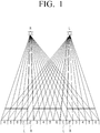
- FIG. 1 is a view for explaining operation of a glasses-free 3D display apparatus in order to help with an understanding of the exemplary embodiments.
- FIG. 1 shows an operation way of an apparatus that provides three-dimensional images in a glasses-free manner by displaying multi-view images according to an embodiment of the present disclosure.
- the multi-view images include a plurality of images of the same object taken at different angles.
- the plurality of images taken at different viewpoints is refracted by angles different from each other, and then focused images are provided to a position that is spaced a certain distance (e.g., about 3m) that is the so-called viewing distance.
- the position where these images are formed is referred to as a viewing area. If one eye of a user is placed at a first viewing area and the other eye of the user is placed at a second viewing area, the user can feel a three-dimensional impression.
- FIG. 1 is a view for explaining a display operation of a multi-view image having a total of 6 viewpoints.
- the glasses-free 3D display apparatus allows light corresponding to a first viewpoint image among six viewpoint images to be projected to the left eye and allows light corresponding to a second viewpoint image to be projected to the right eye. Accordingly, since the left eye and right eye of the user watches images of viewpoints different from each other, the user is able to feel the three-dimensional impression.
- FIG. 2 is a block diagram illustrating a configuration of a display apparatus according to an embodiment of the present disclosure.
- the display apparatus 100 as illustrated in FIG. 2 may be implemented as various types of display apparatuses such as a TV, a monitor, a cell phone, a personal digital assistance (PDA), a personal computer (PC), a set top PC, a kiosk, a tablet computer, an electronic frame, etc.
- a TV TV
- a monitor a cell phone
- PDA personal digital assistance
- PC personal computer
- set top PC a kiosk
- tablet computer a tablet computer
- an electronic frame etc.
- the display apparatus 100 includes a tracker 110, a crosstalk compensator 120, a display 130 and a controller 140.
- the tracker 110 tracks the position of the user; specifically the position of the user's face, and then provides corresponding information to controller 140.
- the tracker 110 tracks a distance between the display 130 and the position of the user's face, namely, a viewing distance, and then provides corresponding information to the controller 140.
- the tracker 110 may include a photographing unit (not illustrated) and a detection unit (not illustrated).
- the photographing unit (not illustrated) is disposed in the outer region of the display apparatus 100.
- the photographing unit (not illustrated) may be disposed in the center area of the top bezel, the center area of the left side bezel, or the center of the right side bezel of the display apparatus 100.
- the installation position of the photographing unit (not illustrated) is not limited to this description.
- the photographing unit photographs the user.
- the photographing unit (not illustrated) includes a lens module having lenses and an image sensor. A shape inputted through the lens is inputted to the image sensor that serves as a film as an optical signal and the image sensor converts the inputted optical signal into an electrical signal and then transmits the electrical signal to the detection unit (not illustrated).
- the photographing unit (not illustrated) may be implemented as a stereo camera, a depth camera, etc. that can detect the user's viewing distance.
- the detection unit detects the position of the user's face from the user photographing image received from the photographing unit (not illustrated), and then tracks the position of the user face. In particular, the detection unit (not illustrated) tracks a moving position of the user based on the positions of the user's face area that are detected from the previous frame and the current frame, and provides the corresponding information to the controller 140.
- a direct recognition method and a method using statistics may be used.
- the direct recognition method creates a rule by using physical features, such as a contour, a skin color, sizes of components, distances between the components, etc. of the face image on the screen, and then performs comparison, inspection and measurement, based on the rule.
- the method using the statistics can detect the face area according to a pre-learned algorithm.
- the method using the statistics is a method that analyzes the face by creating data of inherent characteristics of the input face, and then by comparing the data with large amounts of data in a prepared database (shapes of the faces and other objects).
- the face area may be detected according to a pre-learned algorithm, and a method such as the multi-layer perceptron (MLP) and the support vector machine (SVM) may be used. A detail description thereof will be omitted.
- MLP multi-layer perceptron
- SVM support vector machine
- the user's viewing distance may be detected from the photographed user image received from the photographing unit (not illustrated), and then may be provided to the controller 140.
- the viewing distance may be automatically detected from an image photographed by the camera.
- the detection of the viewing distance is not limited to this description.
- the viewing distance may be implemented to be directly set by user.
- the user can set the viewing distance by using an on screen display menu (OSD menu) that is provided in the display apparatus 100, buttons that are provided by viewing distances in a remote controller, etc.
- OSD menu on screen display menu
- the crosstalk compensator 120 compensates for crosstalk based on a crosstalk matrix defining crosstalk that occurs between the multi-view images.
- the multi-view images may be generated based on the stereo-images and the depth map, or images that are captured in an angle which corresponds to each view.
- the method of generating the multi-view images is technology of the related art; a detailed description thereof will therefore be omitted.
- the crosstalk compensator 120 may compensate for the crosstalk by using the inverse matrix of the pre-defined crosstalk matrix.
- a method to calculate the inverse matrix of the crosstalk matrix will be briefly described.
- brightness of an input signal of each view is defined as I 1 , I 2 , ..., I n , ..., I N
- output brightness that is actually measured due to the crosstalk between the views is defined as I' 1 , I' 2 , ..., I' n , ..., I' N
- the output brightness I' n of an nth image may be expressed as the combination using weight of input images like Formula 1.
- I ′ n a 1 . I 1 + a 2 ⁇ I 2 + ... + a n .
- a 1 to a N refers to the degree of impact which each of the input images gives to the output brightness I' n .
- a n being 0.7
- 70% of the nth image is output as the nth view
- the remaining 30% of the nth image refers to light that is leaked and inputted from the different views.
- the output of the display may be corrected by providing the multi-view signals that are compensated for by multiplying the inverse matrix of the crosstalk matrix to the input signal that is required to output the brightness of I 1 , I 2 , ..., I n , ..., I N to the display.
- the multi-view signals may be compensated for by multiplying the inverse matrix of the crosstalk matrix to a pixel matrix that is configured of pixel values of the multi-view images.
- the crosstalk compensator 120 may compensate for the crosstalk by using the crosstalk matrix divided by each color.
- the crosstalk compensator 120 can compensate for the crosstalk pixel-by-pixel by using a discrete crosstalk matrix that is predefined with respect to each of R, G, and B pixels.
- the crosstalk compensator 120 may convert the multi-view image signal into a signal that is linear to the brightness for performing the crosstalk compensation operation for the multi-view image.
- the multi-view image signal may be converted into a linear RGB signal having a linear relationship with the brightness, and then the crosstalk compensation may be performed.
- the display 130 performs a function to provide multi-views (or multi-optical views).
- the display 130 includes a display panel 131 and a view area separation portion 132 for providing the multi-views.
- the display panel 131 includes a plurality of pixels that are configured of a plurality of sub pixels. Each sub pixel may be configured of red (R), green (G) and blue (B) sub pixels. In other words, pixels configured of the sub pixels of R, G, and B are arranged in a plurality of row and column directions so as to constitute the display panel 131.
- the display panel 131 may be implemented as various types of display units such as a liquid crystal display panel (LCD panel), a plasma display panel (PDP), an organic light emitting diode (OLED), a vacuum fluorescent display (VFD), a field emission display (FED), an electro luminescence display (ELD), etc.
- LCD panel liquid crystal display panel
- PDP plasma display panel
- OLED organic light emitting diode
- VFD vacuum fluorescent display
- FED field emission display
- ELD electro luminescence display
- the display panel 131 displays image frames.
- the display panel 131 may display the image frames in which a plurality of images having different viewpoints from each other are disposed sequentially and repeatedly.
- the display apparatus 100 may be equipped with a backlight unit (not illustrated) to provide backlight to the display panel 131, and a panel driving unit (not illustrated) to drive the pixels of the display panel 131 according to a pixel value of each of the pixels constituting the image frame.
- the display panel 131 displays the image frame by adjusting the transmittance for light that is incident on each pixel according to the image signal.
- the display panel 131 includes a liquid crystal layer and two electrodes that are formed on opposite surfaces of the liquid crystal layer. In response to a voltage being applied to the two electrodes, an electric field is generated to move molecules of the liquid crystal layer between the two electrodes, thereby adjusting the transmittance of the light.
- the view area separation portion 132 is disposed in a front surface of the display panel 131, and may provide different viewpoints by viewing areas, namely, multi-views.
- the view area separation portion 132 may be implemented as a lenticular lens, or as a parallax barrier.
- the view area separation portion 132 may be implemented as the lenticular lens which includes a plurality of lens areas. Accordingly, the lenticular lens can refract the image that is being displayed on the display panel 131 through the plurality of lens areas.
- Each lens area is formed in the size which corresponds to at least one pixel, and may allow the light passing through each pixel to be dispersed differently by viewing areas.
- the view area separation portion 132 may be implemented as a parallax barrier.
- the parallax barrier is implemented as a transparent slit array including a plurality of barrier areas. Accordingly, the parallax barrier may allow an image that has a different viewpoint, by viewing areas, to be emitted by blocking the light through slits between the barrier areas.
- the view area separation portion 132 may operate in a state when it is tilted at a certain angle, in order to improve the quality of the image.
- the controller 140 divides the image frames of each of images that are photographed at a plurality of viewpoints based on the angle at which the view area separation portion 132 is tilted, and may then generate image frames by combining them. Accordingly, the user watches not images that are displayed in a vertical direction or a horizontal direction on the sub pixels of the display panel 131, but rather views images that are displayed to have a certain gradient on the sub pixels.
- FIG. 3 is a view for explaining an example of a display to be implemented according to an exemplary embodiment.
- the display 130 includes the display panel 131, the view area separation portion 132, and the backlight 133.
- the view area separation portion 132 is implemented as a lenticular lens array.
- the display panel 131 includes a plurality of pixels that is divided by a plurality of columns. Images having different viewpoints are disposed in each column. According to FIG. 3 , a plurality of images 1, 2, 3 and 4 having different viewpoints is arranged sequentially and repeatedly. In other words, each of the pixel columns is arranged in a group that is numbered as 1, 2, 3 and 4. A graphic signal that is applied to the panel is arranged so that the pixel column 1 displays the first image, and the pixel column 2 displays the second image.
- the backlight 133 provides light to the display panel 131.
- the images 1, 2, 3, and 4 that are formed in the display panel 131 are projected to the view area separation portion 132 by the light being provided by the backlight 133, and the view area separation portion 132 disperses and transmits the light of each of the projected images 1, 2, 3 and 4 toward the user.
- the view area separation portion 132 generates exit pupils at the viewer's position, namely, at the viewing distance.
- the interval of the slits when the view area separation portion 132 is implemented as the parallax barrier, may be designed so that the exit pupils generated by each column are separated by the average center distance of both eyes of less than 65 mm.
- Each of the separated image lights forms a viewing area.
- the first to the fourth views are formed, and in response to the left eye and right eye of the user being placed at the second view and the third view, the user can watch 3D images.
- the controller 140 controls overall operations of the display apparatus 100.
- the controller 140 may perform control function to display the image frames by rendering the image frames based on the distance between the display panel 131 and the view area separation portion 132 so that different views are spaced apart at regular intervals.
- each view may be generated by using a plurality of virtual viewpoint images, which is not related to the technical features of the exemplary embodiments, so a detailed description thereof will be omitted.
- the controller 140 determines at least two views that will be provided as images for the left and right eyes of the user from among the multi-views based on the user's face position that is tracked by the tracker 110, and may control the crosstalk compensator 120 to compensate for the crosstalk by applying a preset weight to the at least two determined views.
- the controller 140 may control the crosstalk compensator 120 to generate a weight matrix configured to apply a weight higher than a weight to be applied to the remaining views to the at least two views being provided as the images for the left and right eyes of the user among the multi-views, and to compensate for the crosstalk by applying the weight matrix and the inverse matrix of the crosstalk matrix to the multi-view images.
- the weight matrix may become in the form of a diagonal matrix, and this will be described later with reference to the drawings.
- controller 140 may control the crosstalk compensator 120 to compensate for the crosstalk by applying the inverse matrix of the crosstalk matrix and a weight matrix configured of different values depending on the distance between the display unit 130 and the user's face, namely, the viewing distance to the multi-view images.
- controller 140 may control the crosstalk compensator 120 to compensate for the crosstalk by applying a weight matrix that is configured to apply a predetermined weight to a different number of views, depending on the viewing distance to the multi-view images.
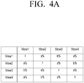
- FIGS. 4A and 4B are views which illustrate a configuration of a crosstalk matrix according to an exemplary embodiment.
- the crosstalk matrix may be composed of values reflecting the optical characteristics of the multi-views.
- the crosstalk matrix as illustrated in FIG. 4A , has four views.
- the number of rows and columns that constitute the matrix may be changed depending on the number of views.
- a%, a%, and b% may be light (crosstalk) that is leaked and enters from view 1, view 3, and view 4, respectively.
- crosstalk matrix may be pre-stored, and each numerical value of the pre-stored crosstalk matrix may be made of values that were previously measured through experiments.
- the crosstalk matrix may be configured to have different values by types of the display apparatus 100.
- a plurality of crosstalk matrixes which correspond to the distance between the display 130 and the user may be stored. These also may be made up of values that were previously measured through experiments.
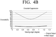
- FIG. 4B is a view which illustrates the effect of crosstalk reduction in response to the crosstalk matrix, according to FIG. 4A , being applied.
- the crosstalk occurring in all the views may be reduced as a whole.
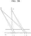
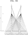
- FIGS. 5A to 5D are views for explaining a multi-view watching method in response to a user's face position, namely, a user's eye position, being moved to help with an understanding of the exemplary embodiments.
- the user's left eye and right eye recognize the fourth view and fifth view.
- the user's left eye and right eye recognize the second view and third view.
- the views recognized by the user's left and right eyes may be changed.
- the viewing distance of the user in response to the viewing distance of the user is changed, the views recognized by the user's left and right eyes may be changed.
- the viewing distance being L1 in response to the viewing distance being L1, light corresponding to the first view is emitted to the left eye and light corresponding to the second view is emitted to the right eye.
- the second view image as well as the first view image may be projected to the viewer's left eye.
- the first view image as well as the second view image may be projected to the viewer's right eye.
- the crosstalk when compensating for the crosstalk by tracking the user's eye position, the crosstalk is compensated for by giving weight to the view that is recognized by the user from among the multi-views.
- an exemplary embodiment may use a weight matrix. Therefore, various types of weight matrixes will be hereinafter described.
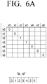
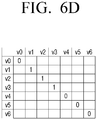
- FIGS. 6A to 6E are views for explaining types of weight matrixes according to various exemplary embodiments.
- FIGS. 6A to 6E an assumption is made that the number of multi-views is six.
- the weight matrix may be configured so that the weight is applied only to the views that are inputted to the left and right eyes of the user.
- the crosstalk compensation may be performed for the second and third views that are inputted to the left and right eyes of the user, and crosstalk compensation may not be performed for the remaining views.
- the weight matrix may be configured so that the weight is applied to the views that are inputted to the left and right eyes of the user and their adjacent views.
- crosstalk compensation may be performed for the first and fourth views adjacent to the second and third views as well as for the second and third views that are inputted to the left and right eyes of the user.
- crosstalk compensation may be performed mainly for the second and third views by applying a weight larger than a weight to be given to the first and fourth views to the second and third views.
- a weight of one (1) is given to the second and third views, and a weight of 0.2 is given to the first and fourth views.
- the weight is not limited by these.
- the weight matrix may be configured so that different weights are given to the adjacent views depending on the position of the left and right eyes of the user.
- the crosstalk may be compensated for by giving a weight larger than a weight to be given to the first view adjacent to the second view to the fourth view adjacent to the third view.
- a weight of 0.8 is given to the second and third views, and weights of 0.1 and 0.5 are given to the first and fourth views, respectively.
- the weight is not limited to this description.
- the weight matrix may be configured to compensate for the viewing distance.
- the number of views that are inputted to the left and right eyes of the user may vary depending on the viewing distance, so that this point may be compensated for.
- the same weight as that of the second and third views may be applied to the first view as well as the second and third views depending on the viewing distance.
- This may be provided based on a predefined resource representing influence of each of views according to the viewing distance as illustrated in FIG. 7C .
- the weight matrix may be used by real time updating of the predefined weight matrix depending on the position of the user's face or the predefined weight matrix may be used to compensate for the viewing distance, as well as the position of the user's face.
- the weight matrix may be configured so that the crosstalk is compensated for by considering two or more viewers.
- the weight may be applied to the fourth and fifth views as well as the first and second views so that the crosstalk is compensated.
- the tracker 110 may be implemented in order to track positions of a plurality of user's faces.
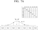
- FIGS. 7A to 7C are views for explaining a method for calculating a weight matrix according to an exemplary embodiment.
- Values of weights for implementing the weight matrix may be discretely sampled from a normalized distribution being centered around the tracked eye position.
- Formula 3 is an equation to calculate a weight value from a normalized distribution being centered around the tracked eye position.
- w v N ⁇ ⁇ 2 v wherein ⁇ is a tracked position of a user's eye, and v represents a discrete viewpoint.
- FIG. 7A is a graph to represent Formula 3, namely, a graph to represent values of N ( ⁇ , ⁇ 2 ) depending on ⁇ .
- the weight matrix may be implemented in the form of a diagonal matrix of the weight values that are calculated by Formula 3, like Formula 4.
- W diag w
- the weight values for implementing the weight matrix may be implemented to compensate for the viewing distance.
- Formula 5 is an equation to calculate the weight values that are implemented to compensate for the viewing distance.
- w v N ⁇ , ⁇ 2 d v v
- d v numerically represents the viewing distance
- ⁇ 2 (d v ) may have a shape that is illustrated in FIG. 7B .
- FIG. 7C is a view which illustrates the influence between views according to the viewing distance d v .
- the weight may be applied to the first to third views as illustrated in FIG. 6D .
- Formula 6 may be used.
- W(d v ) means a weight matrix that reflects viewing distances as described above.
- FIG. 8 is a flowchart for explaining a method of controlling a multi-view image display apparatus according to an exemplary embodiment.
- a position of a user's face is being while the user's position is moved (S810).
- the crosstalk is compensated for by applying a predetermined weight to the at least two determined views by using a crosstalk matrix defining the crosstalk that occurs between multi-view images (S830).
- step S830 to compensate for the crosstalk may determine at least two views that will be provided as images for the user's left and right eyes based on the tracked position of the user's face and the viewing distance, and may compensate for the crosstalk by applying a predetermined weight to the at least two determined views.
- the crosstalk may be compensated for between the multi-view images by multiplying the inverse matrix of the crosstalk matrix to a pixel matrix configured of pixel values of the multi-view images.
- the crosstalk may be compensated for by applying a weight matrix that is configured to a weight higher than a weight to be applied to the remaining views, to at least two views of the inverse matrix of the crosstalk matrix.
- the crosstalk may be compensated for by applying a weight matrix that is configured to apply a predetermined weight to a different number of views, depending on a viewing distance to the inverse matrix of the crosstalk matrix.
- the crosstalk may be compensated for in response to there being a plurality of users, by applying a weight matrix that is configured to apply a predetermined weight to at least four views that will be provided as images for the left and right eyes of each of the plurality of users to the inverse matrix of the crosstalk matrix.
- the crosstalk matrix may be a matrix that is predefined by considering the characteristics of the display on which the multi-view images are displayed.
- the three-dimensional experience may be increased through crosstalk reduction of the glasses-free 3D display.
- the method of controlling a multi-view image display apparatus may be implemented as a program so as to be provided to a display apparatus.
- a non-transitory computer-readable storage medium in which a program to perform a step of determining at least two views that will be provided as images for the user's left and right eyes from among the multi-views, based on the tracked position of a user's face, and a step of compensating for crosstalk by applying a predetermined weight to the at least two determined views by using a crosstalk matrix defining the crosstalk that occurs between the multi-view images is stored, may be provided.
- the non-transitory computer-readable storage medium refers to a medium that can store data in a semi-permanent manner and that can be read by devices.
- the above-described various applications or programs may be stored in and provided with the non-transitory computer readable medium such as a CD, a DVD, a hard discTM, a Blu-ray disc, an USB, a memory card, a ROM, etc.
Landscapes
- Engineering & Computer Science (AREA)
- Multimedia (AREA)
- Signal Processing (AREA)
- Physics & Mathematics (AREA)
- General Physics & Mathematics (AREA)
- Theoretical Computer Science (AREA)
- Computer Vision & Pattern Recognition (AREA)
- Control Of Indicators Other Than Cathode Ray Tubes (AREA)
- Testing, Inspecting, Measuring Of Stereoscopic Televisions And Televisions (AREA)
Claims (10)
- Brillenlose Mehrfachansichtsbild-Anzeigevorrichtung (100), die Folgendes umfasst:eine Anzeige (130);einen Tracker (110), der dazu ausgelegt ist, eine Position eines Gesichts eines Benutzers gemäß einer Bewegung des Benutzers zu verfolgen;einen Übersprechkompensator (120), der dazu ausgelegt ist, Übersprechen bezüglich des Mehrfachansichtsbildes unter Verwendung einer Übersprechmatrix, die das zwischen unterschiedlichen Ansichten auftretende Übersprechen definiert, und durch Multiplizieren einer inversen Matrix der Übersprechmatrix mit einer Pixelmatrix, die Pixelwerte des Mehrfachansichtsbildes umfasst, zu kompensieren; undeine Steuerung (140), die ausgelegt ist zum:Bestimmen von mindestens zwei Ansichten, die durch das linke und rechte Auge des Benutzers erkannt werden und als Bilder für ein linkes Auge und ein rechtes Auge bereitgestellt werden sollen, aus den Mehrfachansichtsbildern basierend auf der verfolgten Position des Gesichts des Benutzers; undSteuern der Anzeige (130), das kompensierte Mehrfachansichtsbild anzuzeigen;dadurch gekennzeichnet, dass:die Steuerung dazu ausgelegt ist, den Übersprechkompensator (120) zu steuern, das Übersprechen durch Anwenden einer Gewichtungsmatrix an der inversen Matrix der Übersprechmatrix zu kompensieren, wobei die Gewichtungsmatrix dazu ausgelegt ist, eine vorbestimmte Gewichtung an den mindestens zwei bestimmten Ansichten anzuwenden;wobei die an den mindestens zwei bestimmten Ansichten angewendete vorbestimmte Gewichtung höher als eine Gewichtung ist, die an mindestens einer verbleibenden Ansicht angewendet wird; undwobei die vorbestimmten Gewichtungen mit einem Betrachtungsabstand des Benutzers variieren.
- Brillenlose Mehrfachansichtsbild-Anzeigevorrichtung (100) nach Anspruch 1, wobei die Steuerung (140) die mindestens zwei bestimmten Ansichten, die als die Bilder für das linke Auge und das rechte Auge des Benutzers bereitgestellt werden sollen, basierend auf der verfolgten Position des Gesichts des Benutzers und dem Betrachtungsabstand des Benutzers bestimmt.
- Brillenlose Mehrfachansichtsbild-Anzeigevorrichtung (100) nach Anspruch 1 oder 2, wobei die Gewichtungsmatrix dazu ausgelegt ist, eine vorbestimmte Gewichtung an einer Anzahl von Ansichten nebenliegend zu den mindestens zwei Ansichten, in Abhängigkeit vom Betrachtungsabstand des Benutzers anzuwenden.
- Brillenlose Mehrfachansichtsbild-Anzeigevorrichtung (100) nach einem der Ansprüche 1 bis 3, wobei die Gewichtungsmatrix dazu ausgelegt ist, die vorbestimmte Gewichtung an mindestens vier Ansichten anzuwenden, die als Reaktion darauf, dass es mehrere Benutzer gibt, als Bilder für linke und rechte Augen von jedem der mehreren Benutzer bereitgestellt werden.
- Brillenlose Mehrfachansichtsbild-Anzeigevorrichtung (100) nach einem der Ansprüche 1 bis 4, wobei
die Übersprechmatrix eine Matrix umfasst, die unter Berücksichtigung von Charakteristiken der Anzeige (130) vordefiniert ist. - Verfahren zum Steuern einer brillenlosen Mehrfachansichtsbild-Anzeigevorrichtung (100), wobei das Steuerverfahren Folgendes umfasst:Verfolgen einer Position eines Gesichts eines Benutzers gemäß einer Bewegung des Benutzers (S810) ;Bestimmen von mindestens zwei Ansichten, die durch das linke und rechte Auge des Benutzers erkannt und als Bilder für ein linkes und ein rechtes Auge bereitgestellt werden, aus den Mehrfachansichtsbildern basierend auf der verfolgten Position des Gesichts des Benutzers (S820) ;Kompensieren von Übersprechen durch Verwenden einer Übersprechmatrix, die das zwischen Mehrfachansichtsbildern auftretende Übersprechen definiert (S830), und durch Multiplizieren einer inversen Matrix der Übersprechmatrix mit einer Pixelmatrix, die Pixelwerte des Mehrfachansichtsbildes umfasst; undAnzeigen der Mehrfachansichtsbilder, die für Übersprechen kompensiert sind (S840);dadurch gekennzeichnet, dass:das Kompensieren des Übersprechens Anwenden einer Gewichtungsmatrix an der inversen Matrix der Übersprechmatrix umfasst, wobei die Gewichtungsmatrix dazu ausgelegt ist, eine vorbestimmte Gewichtung an den mindestens zwei bestimmten Ansichten anzuwenden;wobei die an den mindestens zwei bestimmten Ansichten angewendete vorbestimmte Gewichtung höher als eine Gewichtung ist, die an mindestens einer verbleibenden Ansicht angewendet wird; undwobei die vorbestimmten Gewichtungen mit einem Betrachtungsabstand des Benutzers variieren.
- Steuerverfahren nach Anspruch 6, wobei das Kompensieren des Übersprechens Bestimmen der mindestens zwei bestimmten Ansichten basierend auf der verfolgten Position des Gesichts des Benutzers und dem Betrachtungsabstand des Benutzers umfasst.
- Steuerverfahren nach Anspruch 6 oder 7, wobei die Gewichtungsmatrix dazu ausgelegt ist, eine vorbestimmte Gewichtung an einer Anzahl von Ansichten nebenliegend zu den mindestens zwei Ansichten in Abhängigkeit vom Betrachtungsabstand anzuwenden.
- Steuerverfahren nach einem der Ansprüche 6 bis 8, wobei die Gewichtungsmatrix dazu ausgelegt ist, die vorbestimmte Gewichtung an mindestens vier Ansichten anzuwenden, die als Reaktion darauf, dass es mehrere Benutzer gibt, als Bilder für linke und rechte Augen von jedem der mehreren Benutzer bereitgestellt werden.
- Steuerverfahren nach einem der Ansprüche 6 bis 9, wobei die Übersprechmatrix eine Matrix umfasst, die unter Berücksichtigung von Charakteristiken einer Anzeige, auf der die Mehrfachansichtsbilder angezeigt werden, vordefiniert ist.
Applications Claiming Priority (1)
| Application Number | Priority Date | Filing Date | Title |
|---|---|---|---|
| KR1020130115326A KR102140080B1 (ko) | 2013-09-27 | 2013-09-27 | 다시점 영상 디스플레이 장치 및 제어 방법 |
Publications (2)
| Publication Number | Publication Date |
|---|---|
| EP2854402A1 EP2854402A1 (de) | 2015-04-01 |
| EP2854402B1 true EP2854402B1 (de) | 2020-03-18 |
Family
ID=50478673
Family Applications (1)
| Application Number | Title | Priority Date | Filing Date |
|---|---|---|---|
| EP14160483.5A Active EP2854402B1 (de) | 2013-09-27 | 2014-03-18 | Mehrfachbildanzeigevorrichtung und Steuerverfahren dafür |
Country Status (4)
| Country | Link |
|---|---|
| US (1) | US9866825B2 (de) |
| EP (1) | EP2854402B1 (de) |
| KR (1) | KR102140080B1 (de) |
| CN (1) | CN104519344B (de) |
Families Citing this family (33)
| Publication number | Priority date | Publication date | Assignee | Title |
|---|---|---|---|---|
| US9674510B2 (en) * | 2012-11-21 | 2017-06-06 | Elwha Llc | Pulsed projection system for 3D video |
| US9779651B2 (en) * | 2013-06-20 | 2017-10-03 | Mitsubishi Electric Corporation | Image processing device, method, and program, and image display device |
| JP2015154091A (ja) * | 2014-02-10 | 2015-08-24 | ソニー株式会社 | 画像処理方法、画像処理装置、及び電子機器 |
| US9716879B2 (en) * | 2014-07-15 | 2017-07-25 | Shenzhen China Star Optoelectronics Technology Co., Ltd | Image display method and device for multi-view stereoscopic display |
| US10701349B2 (en) | 2015-01-20 | 2020-06-30 | Misapplied Sciences, Inc. | Method for calibrating a multi-view display |
| US11099798B2 (en) | 2015-01-20 | 2021-08-24 | Misapplied Sciences, Inc. | Differentiated content delivery system and method therefor |
| US10955924B2 (en) | 2015-01-29 | 2021-03-23 | Misapplied Sciences, Inc. | Individually interactive multi-view display system and methods therefor |
| US10928914B2 (en) | 2015-01-29 | 2021-02-23 | Misapplied Sciences, Inc. | Individually interactive multi-view display system for non-stationary viewing locations and methods therefor |
| US10264247B2 (en) | 2015-02-03 | 2019-04-16 | Misapplied Sciences, Inc. | Multi-view displays |
| CA2978717C (en) * | 2015-03-03 | 2023-06-20 | Misapplied Sciences, Inc. | System and method for displaying location dependent content |
| US10362301B2 (en) | 2015-03-05 | 2019-07-23 | Misapplied Sciences, Inc. | Designing content for multi-view display |
| US10613699B2 (en) * | 2015-06-11 | 2020-04-07 | Misapplied Sciences, Inc. | Multi-view display cueing, prompting, and previewing |
| KR102415502B1 (ko) * | 2015-08-07 | 2022-07-01 | 삼성전자주식회사 | 복수의 사용자를 위한 라이트 필드 렌더링 방법 및 장치 |
| KR102121389B1 (ko) * | 2015-10-16 | 2020-06-10 | 삼성전자주식회사 | 무안경 3d 디스플레이 장치 및 그 제어 방법 |
| US10602131B2 (en) | 2016-10-20 | 2020-03-24 | Misapplied Sciences, Inc. | System and methods for wayfinding and navigation via multi-view displays, signage, and lights |
| US10353535B2 (en) | 2016-10-21 | 2019-07-16 | Misapplied Sciences, Inc. | Multi-view display viewing zone layout and content assignment |
| US10269279B2 (en) | 2017-03-24 | 2019-04-23 | Misapplied Sciences, Inc. | Display system and method for delivering multi-view content |
| US12417752B2 (en) | 2017-06-13 | 2025-09-16 | Misapplied Sciences, Inc. | Coordinated multi-view display experiences |
| US10427045B2 (en) | 2017-07-12 | 2019-10-01 | Misapplied Sciences, Inc. | Multi-view (MV) display systems and methods for quest experiences, challenges, scavenger hunts, treasure hunts and alternate reality games |
| US10565616B2 (en) | 2017-07-13 | 2020-02-18 | Misapplied Sciences, Inc. | Multi-view advertising system and method |
| US10404974B2 (en) | 2017-07-21 | 2019-09-03 | Misapplied Sciences, Inc. | Personalized audio-visual systems |
| US10778962B2 (en) | 2017-11-10 | 2020-09-15 | Misapplied Sciences, Inc. | Precision multi-view display |
| KR102092242B1 (ko) | 2018-06-04 | 2020-03-23 | 한국항공우주산업 주식회사 | 항공기 시뮬레이션용 디스플레이 장치 |
| EP3848783B1 (de) * | 2018-09-07 | 2023-12-06 | Alps Alpine Co., Ltd. | Sensorvorrichtung und steuerungsverfahren und programm dafür |
| CN112929634A (zh) * | 2019-12-05 | 2021-06-08 | 北京芯海视界三维科技有限公司 | 多视点裸眼3d显示设备和3d图像显示方法 |
| KR102790277B1 (ko) | 2020-11-18 | 2025-04-03 | 삼성전자주식회사 | 디스플레이 장치 및 그의 제어 방법 |
| KR20220157147A (ko) | 2021-05-20 | 2022-11-29 | 삼성전자주식회사 | 이미지를 처리하기 위한 방법 및 장치 |
| WO2023092595A1 (zh) * | 2021-11-29 | 2023-06-01 | 京东方科技集团股份有限公司 | 三维图像数据的处理方法及装置、设备和介质 |
| CN115134576B (zh) * | 2022-06-27 | 2025-11-25 | 小豆视觉(重庆)医疗科技有限公司 | 用于降低3d串扰的方法和立体图像显示装置 |
| KR20240098287A (ko) * | 2022-12-20 | 2024-06-28 | 삼성디스플레이 주식회사 | 크로스토크 평가 방법 및 이를 수행하는 크로스토크 평가 장치 |
| US12495135B2 (en) | 2024-01-30 | 2025-12-09 | Apple Inc. | Crosstalk correction in displays |
| CN119166957B (zh) * | 2024-11-21 | 2025-03-07 | 长春长光辰谱科技有限公司 | 基于多通道线性系数逆矩阵的去串扰方法 |
| CN120263960B (zh) * | 2025-06-09 | 2025-08-19 | 安徽玄视界控股有限责任公司 | 一种裸眼3d大屏的虚实交互方法及系统 |
Family Cites Families (12)
| Publication number | Priority date | Publication date | Assignee | Title |
|---|---|---|---|---|
| KR100704634B1 (ko) * | 2005-12-19 | 2007-04-09 | 삼성전자주식회사 | 사용자의 위치에 따른 입체 영상을 디스플레이하는 장치 및방법 |
| WO2009095862A1 (en) * | 2008-02-01 | 2009-08-06 | Koninklijke Philips Electronics N.V. | Autostereoscopic display device |
| US20100060667A1 (en) * | 2008-09-10 | 2010-03-11 | Apple Inc. | Angularly dependent display optimized for multiple viewing angles |
| KR20100063300A (ko) * | 2008-12-03 | 2010-06-11 | 삼성전자주식회사 | 3차원 디스플레이에서 뷰간 누화를 보상하는 장치 및 방법 |
| US8358335B2 (en) | 2009-11-30 | 2013-01-22 | Fraunhofer-Gesellschaft Zur Foerderung Der Angewandten Forschung E.V. | Method for displaying image information and autostereoscopic screen |
| KR101669498B1 (ko) * | 2009-11-30 | 2016-10-27 | 프라운호퍼 게젤샤프트 쭈르 푀르데룽 데어 안겐반텐 포르슝 에. 베. | 이미지 정보를 표시하는 방법 및 자동입체이미지 스크린 |
| JP5289416B2 (ja) | 2010-11-10 | 2013-09-11 | 株式会社東芝 | 立体画像表示装置、方法およびプログラム |
| JP2013026808A (ja) * | 2011-07-21 | 2013-02-04 | Sony Corp | 画像処理装置および方法、並びにプログラム |
| US20130063575A1 (en) * | 2011-09-14 | 2013-03-14 | Broadcom Corporation | System and method for viewing angle compensation for polarized three dimensional display |
| KR101867815B1 (ko) | 2011-10-21 | 2018-06-18 | 엘지전자 주식회사 | 입체영상 처리 장치 및 입체영상의 시역 거리를 조절하기 위한 방법 |
| CN102395039B (zh) * | 2011-11-18 | 2013-09-11 | 南开大学 | 一种随动照明的自由立体视频图像显示器 |
| TWI452345B (zh) | 2012-10-26 | 2014-09-11 | Au Optronics Corp | 立體顯示器及其顯示方法 |
-
2013
- 2013-09-27 KR KR1020130115326A patent/KR102140080B1/ko active Active
-
2014
- 2014-03-18 EP EP14160483.5A patent/EP2854402B1/de active Active
- 2014-06-25 CN CN201410294958.6A patent/CN104519344B/zh not_active Expired - Fee Related
- 2014-07-08 US US14/326,086 patent/US9866825B2/en active Active
Non-Patent Citations (1)
| Title |
|---|
| None * |
Also Published As
| Publication number | Publication date |
|---|---|
| CN104519344A (zh) | 2015-04-15 |
| KR102140080B1 (ko) | 2020-07-31 |
| US9866825B2 (en) | 2018-01-09 |
| KR20150035117A (ko) | 2015-04-06 |
| EP2854402A1 (de) | 2015-04-01 |
| US20150092026A1 (en) | 2015-04-02 |
| CN104519344B (zh) | 2018-05-04 |
Similar Documents
| Publication | Publication Date | Title |
|---|---|---|
| EP2854402B1 (de) | Mehrfachbildanzeigevorrichtung und Steuerverfahren dafür | |
| US9088790B2 (en) | Display device and method of controlling the same | |
| KR102185130B1 (ko) | 다시점 영상 디스플레이 장치 및 그 제어 방법 | |
| KR102121389B1 (ko) | 무안경 3d 디스플레이 장치 및 그 제어 방법 | |
| KR101966152B1 (ko) | 다시점 영상 디스플레이 장치 및 그 제어 방법 | |
| KR102174258B1 (ko) | 무안경 3d 디스플레이 장치 및 그 제어 방법 | |
| JP6377155B2 (ja) | 多視点映像処理装置及びその映像処理方法 | |
| US20150222888A1 (en) | Display apparatus and controlling method thereof | |
| US20170070728A1 (en) | Multiview image display apparatus and control method thereof | |
| US20170230647A1 (en) | Multiview image display device and control method therefor | |
| US20160014400A1 (en) | Multiview image display apparatus and multiview image display method thereof | |
| US9832458B2 (en) | Multi view image display method in which viewpoints are controlled and display device thereof | |
| KR20150077167A (ko) | 3차원영상 표시장치 및 그 구동방법 | |
| US20260038398A1 (en) | Stereoscopic image display device and method of driving the same, and electronic device including the stereoscopic image display device | |
| US9678354B2 (en) | Glassless multi-view display apparatus and control method thereof | |
| KR20240005492A (ko) | 3d 영상을 제공하는 디스플레이 장치 및 그 제어 방법 | |
| KR20190010060A (ko) | 디스플레이 장치 및 그 제어 방법 |
Legal Events
| Date | Code | Title | Description |
|---|---|---|---|
| PUAI | Public reference made under article 153(3) epc to a published international application that has entered the european phase |
Free format text: ORIGINAL CODE: 0009012 |
|
| 17P | Request for examination filed |
Effective date: 20140318 |
|
| AK | Designated contracting states |
Kind code of ref document: A1 Designated state(s): AL AT BE BG CH CY CZ DE DK EE ES FI FR GB GR HR HU IE IS IT LI LT LU LV MC MK MT NL NO PL PT RO RS SE SI SK SM TR |
|
| AX | Request for extension of the european patent |
Extension state: BA ME |
|
| R17P | Request for examination filed (corrected) |
Effective date: 20151001 |
|
| RBV | Designated contracting states (corrected) |
Designated state(s): AL AT BE BG CH CY CZ DE DK EE ES FI FR GB GR HR HU IE IS IT LI LT LU LV MC MK MT NL NO PL PT RO RS SE SI SK SM TR |
|
| STAA | Information on the status of an ep patent application or granted ep patent |
Free format text: STATUS: EXAMINATION IS IN PROGRESS |
|
| 17Q | First examination report despatched |
Effective date: 20180601 |
|
| REG | Reference to a national code |
Ref country code: DE Ref legal event code: R079 Ref document number: 602014062425 Country of ref document: DE Free format text: PREVIOUS MAIN CLASS: H04N0013040000 Ipc: H04N0013376000 |
|
| GRAP | Despatch of communication of intention to grant a patent |
Free format text: ORIGINAL CODE: EPIDOSNIGR1 |
|
| STAA | Information on the status of an ep patent application or granted ep patent |
Free format text: STATUS: GRANT OF PATENT IS INTENDED |
|
| RIC1 | Information provided on ipc code assigned before grant |
Ipc: H04N 13/122 20180101ALI20191211BHEP Ipc: H04N 13/383 20180101ALI20191211BHEP Ipc: H04N 13/351 20180101ALI20191211BHEP Ipc: H04N 13/373 20180101ALI20191211BHEP Ipc: H04N 13/376 20180101AFI20191211BHEP |
|
| INTG | Intention to grant announced |
Effective date: 20200113 |
|
| GRAS | Grant fee paid |
Free format text: ORIGINAL CODE: EPIDOSNIGR3 |
|
| GRAA | (expected) grant |
Free format text: ORIGINAL CODE: 0009210 |
|
| STAA | Information on the status of an ep patent application or granted ep patent |
Free format text: STATUS: THE PATENT HAS BEEN GRANTED |
|
| AK | Designated contracting states |
Kind code of ref document: B1 Designated state(s): AL AT BE BG CH CY CZ DE DK EE ES FI FR GB GR HR HU IE IS IT LI LT LU LV MC MK MT NL NO PL PT RO RS SE SI SK SM TR |
|
| REG | Reference to a national code |
Ref country code: GB Ref legal event code: FG4D |
|
| REG | Reference to a national code |
Ref country code: DE Ref legal event code: R096 Ref document number: 602014062425 Country of ref document: DE |
|
| REG | Reference to a national code |
Ref country code: AT Ref legal event code: REF Ref document number: 1247271 Country of ref document: AT Kind code of ref document: T Effective date: 20200415 Ref country code: IE Ref legal event code: FG4D |
|
| PG25 | Lapsed in a contracting state [announced via postgrant information from national office to epo] |
Ref country code: NO Free format text: LAPSE BECAUSE OF FAILURE TO SUBMIT A TRANSLATION OF THE DESCRIPTION OR TO PAY THE FEE WITHIN THE PRESCRIBED TIME-LIMIT Effective date: 20200618 Ref country code: FI Free format text: LAPSE BECAUSE OF FAILURE TO SUBMIT A TRANSLATION OF THE DESCRIPTION OR TO PAY THE FEE WITHIN THE PRESCRIBED TIME-LIMIT Effective date: 20200318 Ref country code: RS Free format text: LAPSE BECAUSE OF FAILURE TO SUBMIT A TRANSLATION OF THE DESCRIPTION OR TO PAY THE FEE WITHIN THE PRESCRIBED TIME-LIMIT Effective date: 20200318 |
|
| REG | Reference to a national code |
Ref country code: NL Ref legal event code: MP Effective date: 20200318 |
|
| PG25 | Lapsed in a contracting state [announced via postgrant information from national office to epo] |
Ref country code: GR Free format text: LAPSE BECAUSE OF FAILURE TO SUBMIT A TRANSLATION OF THE DESCRIPTION OR TO PAY THE FEE WITHIN THE PRESCRIBED TIME-LIMIT Effective date: 20200619 Ref country code: HR Free format text: LAPSE BECAUSE OF FAILURE TO SUBMIT A TRANSLATION OF THE DESCRIPTION OR TO PAY THE FEE WITHIN THE PRESCRIBED TIME-LIMIT Effective date: 20200318 Ref country code: LV Free format text: LAPSE BECAUSE OF FAILURE TO SUBMIT A TRANSLATION OF THE DESCRIPTION OR TO PAY THE FEE WITHIN THE PRESCRIBED TIME-LIMIT Effective date: 20200318 Ref country code: SE Free format text: LAPSE BECAUSE OF FAILURE TO SUBMIT A TRANSLATION OF THE DESCRIPTION OR TO PAY THE FEE WITHIN THE PRESCRIBED TIME-LIMIT Effective date: 20200318 Ref country code: BG Free format text: LAPSE BECAUSE OF FAILURE TO SUBMIT A TRANSLATION OF THE DESCRIPTION OR TO PAY THE FEE WITHIN THE PRESCRIBED TIME-LIMIT Effective date: 20200618 |
|
| REG | Reference to a national code |
Ref country code: LT Ref legal event code: MG4D |
|
| PG25 | Lapsed in a contracting state [announced via postgrant information from national office to epo] |
Ref country code: NL Free format text: LAPSE BECAUSE OF FAILURE TO SUBMIT A TRANSLATION OF THE DESCRIPTION OR TO PAY THE FEE WITHIN THE PRESCRIBED TIME-LIMIT Effective date: 20200318 |
|
| PG25 | Lapsed in a contracting state [announced via postgrant information from national office to epo] |
Ref country code: PT Free format text: LAPSE BECAUSE OF FAILURE TO SUBMIT A TRANSLATION OF THE DESCRIPTION OR TO PAY THE FEE WITHIN THE PRESCRIBED TIME-LIMIT Effective date: 20200812 Ref country code: LT Free format text: LAPSE BECAUSE OF FAILURE TO SUBMIT A TRANSLATION OF THE DESCRIPTION OR TO PAY THE FEE WITHIN THE PRESCRIBED TIME-LIMIT Effective date: 20200318 Ref country code: EE Free format text: LAPSE BECAUSE OF FAILURE TO SUBMIT A TRANSLATION OF THE DESCRIPTION OR TO PAY THE FEE WITHIN THE PRESCRIBED TIME-LIMIT Effective date: 20200318 Ref country code: SM Free format text: LAPSE BECAUSE OF FAILURE TO SUBMIT A TRANSLATION OF THE DESCRIPTION OR TO PAY THE FEE WITHIN THE PRESCRIBED TIME-LIMIT Effective date: 20200318 Ref country code: RO Free format text: LAPSE BECAUSE OF FAILURE TO SUBMIT A TRANSLATION OF THE DESCRIPTION OR TO PAY THE FEE WITHIN THE PRESCRIBED TIME-LIMIT Effective date: 20200318 Ref country code: IS Free format text: LAPSE BECAUSE OF FAILURE TO SUBMIT A TRANSLATION OF THE DESCRIPTION OR TO PAY THE FEE WITHIN THE PRESCRIBED TIME-LIMIT Effective date: 20200718 Ref country code: CZ Free format text: LAPSE BECAUSE OF FAILURE TO SUBMIT A TRANSLATION OF THE DESCRIPTION OR TO PAY THE FEE WITHIN THE PRESCRIBED TIME-LIMIT Effective date: 20200318 Ref country code: SK Free format text: LAPSE BECAUSE OF FAILURE TO SUBMIT A TRANSLATION OF THE DESCRIPTION OR TO PAY THE FEE WITHIN THE PRESCRIBED TIME-LIMIT Effective date: 20200318 |
|
| REG | Reference to a national code |
Ref country code: CH Ref legal event code: PL |
|
| REG | Reference to a national code |
Ref country code: AT Ref legal event code: MK05 Ref document number: 1247271 Country of ref document: AT Kind code of ref document: T Effective date: 20200318 |
|
| REG | Reference to a national code |
Ref country code: DE Ref legal event code: R097 Ref document number: 602014062425 Country of ref document: DE |
|
| REG | Reference to a national code |
Ref country code: BE Ref legal event code: MM Effective date: 20200331 |
|
| PG25 | Lapsed in a contracting state [announced via postgrant information from national office to epo] |
Ref country code: LU Free format text: LAPSE BECAUSE OF NON-PAYMENT OF DUE FEES Effective date: 20200318 Ref country code: MC Free format text: LAPSE BECAUSE OF FAILURE TO SUBMIT A TRANSLATION OF THE DESCRIPTION OR TO PAY THE FEE WITHIN THE PRESCRIBED TIME-LIMIT Effective date: 20200318 |
|
| PLBE | No opposition filed within time limit |
Free format text: ORIGINAL CODE: 0009261 |
|
| STAA | Information on the status of an ep patent application or granted ep patent |
Free format text: STATUS: NO OPPOSITION FILED WITHIN TIME LIMIT |
|
| PG25 | Lapsed in a contracting state [announced via postgrant information from national office to epo] |
Ref country code: IE Free format text: LAPSE BECAUSE OF NON-PAYMENT OF DUE FEES Effective date: 20200318 Ref country code: IT Free format text: LAPSE BECAUSE OF FAILURE TO SUBMIT A TRANSLATION OF THE DESCRIPTION OR TO PAY THE FEE WITHIN THE PRESCRIBED TIME-LIMIT Effective date: 20200318 Ref country code: ES Free format text: LAPSE BECAUSE OF FAILURE TO SUBMIT A TRANSLATION OF THE DESCRIPTION OR TO PAY THE FEE WITHIN THE PRESCRIBED TIME-LIMIT Effective date: 20200318 Ref country code: DK Free format text: LAPSE BECAUSE OF FAILURE TO SUBMIT A TRANSLATION OF THE DESCRIPTION OR TO PAY THE FEE WITHIN THE PRESCRIBED TIME-LIMIT Effective date: 20200318 Ref country code: AT Free format text: LAPSE BECAUSE OF FAILURE TO SUBMIT A TRANSLATION OF THE DESCRIPTION OR TO PAY THE FEE WITHIN THE PRESCRIBED TIME-LIMIT Effective date: 20200318 Ref country code: LI Free format text: LAPSE BECAUSE OF NON-PAYMENT OF DUE FEES Effective date: 20200331 Ref country code: CH Free format text: LAPSE BECAUSE OF NON-PAYMENT OF DUE FEES Effective date: 20200331 |
|
| 26N | No opposition filed |
Effective date: 20201221 |
|
| PG25 | Lapsed in a contracting state [announced via postgrant information from national office to epo] |
Ref country code: BE Free format text: LAPSE BECAUSE OF NON-PAYMENT OF DUE FEES Effective date: 20200331 Ref country code: PL Free format text: LAPSE BECAUSE OF FAILURE TO SUBMIT A TRANSLATION OF THE DESCRIPTION OR TO PAY THE FEE WITHIN THE PRESCRIBED TIME-LIMIT Effective date: 20200318 |
|
| PG25 | Lapsed in a contracting state [announced via postgrant information from national office to epo] |
Ref country code: SI Free format text: LAPSE BECAUSE OF FAILURE TO SUBMIT A TRANSLATION OF THE DESCRIPTION OR TO PAY THE FEE WITHIN THE PRESCRIBED TIME-LIMIT Effective date: 20200318 |
|
| PG25 | Lapsed in a contracting state [announced via postgrant information from national office to epo] |
Ref country code: TR Free format text: LAPSE BECAUSE OF FAILURE TO SUBMIT A TRANSLATION OF THE DESCRIPTION OR TO PAY THE FEE WITHIN THE PRESCRIBED TIME-LIMIT Effective date: 20200318 Ref country code: MT Free format text: LAPSE BECAUSE OF FAILURE TO SUBMIT A TRANSLATION OF THE DESCRIPTION OR TO PAY THE FEE WITHIN THE PRESCRIBED TIME-LIMIT Effective date: 20200318 Ref country code: CY Free format text: LAPSE BECAUSE OF FAILURE TO SUBMIT A TRANSLATION OF THE DESCRIPTION OR TO PAY THE FEE WITHIN THE PRESCRIBED TIME-LIMIT Effective date: 20200318 |
|
| PG25 | Lapsed in a contracting state [announced via postgrant information from national office to epo] |
Ref country code: MK Free format text: LAPSE BECAUSE OF FAILURE TO SUBMIT A TRANSLATION OF THE DESCRIPTION OR TO PAY THE FEE WITHIN THE PRESCRIBED TIME-LIMIT Effective date: 20200318 Ref country code: AL Free format text: LAPSE BECAUSE OF FAILURE TO SUBMIT A TRANSLATION OF THE DESCRIPTION OR TO PAY THE FEE WITHIN THE PRESCRIBED TIME-LIMIT Effective date: 20200318 |
|
| PGFP | Annual fee paid to national office [announced via postgrant information from national office to epo] |
Ref country code: FR Payment date: 20230221 Year of fee payment: 10 |
|
| PGFP | Annual fee paid to national office [announced via postgrant information from national office to epo] |
Ref country code: DE Payment date: 20230220 Year of fee payment: 10 |
|
| REG | Reference to a national code |
Ref country code: DE Ref legal event code: R119 Ref document number: 602014062425 Country of ref document: DE |
|
| PG25 | Lapsed in a contracting state [announced via postgrant information from national office to epo] |
Ref country code: DE Free format text: LAPSE BECAUSE OF NON-PAYMENT OF DUE FEES Effective date: 20241001 |
|
| PG25 | Lapsed in a contracting state [announced via postgrant information from national office to epo] |
Ref country code: FR Free format text: LAPSE BECAUSE OF NON-PAYMENT OF DUE FEES Effective date: 20240331 |
|
| PG25 | Lapsed in a contracting state [announced via postgrant information from national office to epo] |
Ref country code: FR Free format text: LAPSE BECAUSE OF NON-PAYMENT OF DUE FEES Effective date: 20240331 Ref country code: DE Free format text: LAPSE BECAUSE OF NON-PAYMENT OF DUE FEES Effective date: 20241001 |
|
| PGFP | Annual fee paid to national office [announced via postgrant information from national office to epo] |
Ref country code: GB Payment date: 20250224 Year of fee payment: 12 |