EP2854300B1 - Système de convertisseur, système de pitch doté d'un système de convertisseur et procédé de fonctionnement d'un système de convertisseur - Google Patents
Système de convertisseur, système de pitch doté d'un système de convertisseur et procédé de fonctionnement d'un système de convertisseur Download PDFInfo
- Publication number
- EP2854300B1 EP2854300B1 EP13186664.2A EP13186664A EP2854300B1 EP 2854300 B1 EP2854300 B1 EP 2854300B1 EP 13186664 A EP13186664 A EP 13186664A EP 2854300 B1 EP2854300 B1 EP 2854300B1
- Authority
- EP
- European Patent Office
- Prior art keywords
- direct current
- inverter
- inverters
- power
- circuit
- Prior art date
- Legal status (The legal status is an assumption and is not a legal conclusion. Google has not performed a legal analysis and makes no representation as to the accuracy of the status listed.)
- Not-in-force
Links
Images

Classifications
-
- H—ELECTRICITY
- H02—GENERATION; CONVERSION OR DISTRIBUTION OF ELECTRIC POWER
- H02M—APPARATUS FOR CONVERSION BETWEEN AC AND AC, BETWEEN AC AND DC, OR BETWEEN DC AND DC, AND FOR USE WITH MAINS OR SIMILAR POWER SUPPLY SYSTEMS; CONVERSION OF DC OR AC INPUT POWER INTO SURGE OUTPUT POWER; CONTROL OR REGULATION THEREOF
- H02M5/00—Conversion of ac power input into ac power output, e.g. for change of voltage, for change of frequency, for change of number of phases
- H02M5/40—Conversion of ac power input into ac power output, e.g. for change of voltage, for change of frequency, for change of number of phases with intermediate conversion into dc
-
- H—ELECTRICITY
- H04—ELECTRIC COMMUNICATION TECHNIQUE
- H04B—TRANSMISSION
- H04B3/00—Line transmission systems
- H04B3/54—Systems for transmission via power distribution lines
- H04B3/548—Systems for transmission via power distribution lines the power on the line being DC
-
- H—ELECTRICITY
- H02—GENERATION; CONVERSION OR DISTRIBUTION OF ELECTRIC POWER
- H02J—CIRCUIT ARRANGEMENTS OR SYSTEMS FOR SUPPLYING OR DISTRIBUTING ELECTRIC POWER; SYSTEMS FOR STORING ELECTRIC ENERGY
- H02J7/00—Circuit arrangements for charging or depolarising batteries or for supplying loads from batteries
- H02J7/34—Parallel operation in networks using both storage and other dc sources, e.g. providing buffering
-
- H—ELECTRICITY
- H02—GENERATION; CONVERSION OR DISTRIBUTION OF ELECTRIC POWER
- H02J—CIRCUIT ARRANGEMENTS OR SYSTEMS FOR SUPPLYING OR DISTRIBUTING ELECTRIC POWER; SYSTEMS FOR STORING ELECTRIC ENERGY
- H02J9/00—Circuit arrangements for emergency or stand-by power supply, e.g. for emergency lighting
Definitions
- the invention relates to an inverter system having a rectifier and at least two inverters, wherein the rectifier is powered by an AC power source, the rectifier is connected to each of the inverters for power supply via a common DC circuit and each inverter, each with at least one electrical load to power the respective consumer or the respective consumer is connectable.
- Such a converter system serves to supply power to a plurality of electrical consumers from an AC power source.
- the AC power source may be, for example, the utility grid or a generator.
- the rectifier By the rectifier, the AC voltage provided by the AC power source is rectified into a DC voltage. This DC voltage is fed into the common DC circuit.
- the terms DC circuit and DC link are common and can be used synonymously.
- the inverters can remove electrical energy from the DC circuit and operate electrical consumers with this electrical energy.
- the US 7,126,236 B2 discloses a method and system for powering at least one DC motor of a wind turbine, the system comprising a bridge rectifier connected to a power source for generating a DC voltage and providing it to the at least one DC motor and a DC link capacitor the DC voltage smoothes and acts as an energy storage and energy source for the at least one DC motor. Further, it is disclosed that a plurality of DC motors are used, which are powered by separate drive systems, wherein the intermediate circuits of these drive systems are interconnected, so that energy can be exchanged between these intermediate circuits.
- the US 7,740,448 B2 discloses an apparatus for controlling the angle of attack of a rotor blade of a wind turbine, the apparatus comprising: a pitch control system comprising a MOSFET based power converter; a DC circuit having a DC circuit capacitor and being configured to supply power to the pitch control system through the MOSFET based power converter; a source of AC input power for supplying power to the DC circuit; and a backup battery configured to not supply power to the DC circuit when full AC input power is available; and further wherein the apparatus is configured to: use energy stored in the dc capacitor to supply power to the pitch control system during a loss or incursion of ac input power through the mosfet based power converter; and to maintain charge on the dc circuit capacitor using the backup battery as soon as the voltage across the dc circuit capacitor drops while supplying power to the gating control system; wherein the AC source is a non-regenerative source, and the DC circuit is common to a plurality of pitch motor systems; and further wherein maintaining charge on the
- an engine assembly that includes a converter, an inverter, a voltage detector and a numerical controller.
- the converter converts an input AC voltage into a DC current and the inverter converts the DC current of the converter into an AC current for driving an electric motor.
- the voltage detector monitors the voltage on the DC side and increases the power consumption of the electric motor when the monitored voltage exceeds a predetermined limit.
- DE 195 20 596 A1 discloses an arrangement for transmitting data and energy, which has two bus lines to improve reliability, wherein the first bus line, a DC line and the second Bus line is either a DC or AC line.
- the prerequisite for this type of fail-safe communication is that when using a DC bus and an AC power line the communicating devices must be configured so that they can be supplied with either direct current or alternating current.
- WO 2011/136591 A2 is known for indoors suitable DC power supply system, which can be coupled by means of rectifiers AC-powered devices to the DC power supply system.
- the AC devices have AC side modulators / demodulators which allow communication of the AC devices via the DC power supply system.
- the invention further relates to a pitch system of a wind turbine with a Umrichtersytem and a method for operating an inverter system with a rectifier and at least two inverters, wherein the rectifier is powered by an AC power source, the rectifier for power supply to each of the inverters connected via a common DC circuit is and each inverter is connected to a respective electrical consumer for supplying energy to the respective consumer.
- the previously derived and indicated object is achieved on the basis of the converter system described above in that the rectifier has a modulation device in order to modulate a signal to the DC circuit, wherein at least one of the inverters has a demodulation device for demodulating a signal modulated onto the DC circuit.
- the rectifier can modulate a signal to the DC circuit and transmit this signal via the DC circuit to the inverters.
- the modulation can be done in different ways.
- the DC voltage generated by the rectifier can be superimposed on a voltage signal.
- the voltage signal may in this case for example have an amplitude modulation or an angle modulation, such as a phase or frequency modulation.
- Mixed forms, such as vector modulation, are also conceivable.
- Digital modulation techniques such as In particular, the pulse width modulation or the pulse-code modulation can also be used.
- the signal modulated onto the DC circuit can be demodulated and reused by the inverter.
- the demodulated signal can in particular be used to control or regulate an electrical consumer connected to the inverter. This can be done, for example, by the fact that the signal is used by the inverter to specifically supply the electrical consumer with energy. This means in particular that the signal controls or regulates the electrical load indirectly via the power supply by the inverter.
- At least one of the consumers is an AC motor or a DC motor.
- both AC motors and DC motors can be operated by the inverters.
- the term "inverter” also encompasses a family of components which can generate a voltage of any frequency and phase and thus both DC voltage and AC voltage from a DC voltage applied to the input of the inverter.
- An example of this are bridge inverters with semiconductor switching elements.
- At least one of the inverters has a modulation device in order to choirmodulieren a signal to the DC circuit. If one of the Inverter has a modulation device, it can modulate a signal to the DC circuit with this modulation device. This signal, if another inverter has a demodulation device, can be demodulated by this demodulation device. In this way, the individual inverters can communicate with each other. It is particularly advantageous if all inverters have both a modulation device and a demodulation device.
- An advantageous embodiment of the invention is characterized in that the rectifier has a demodulation device in order to demodulate a signal modulated onto the DC circuit.
- the rectifier can demodulate a signal modulated onto the DC circuit. This allows transmission of information not only from the rectifier to the inverters, but also vice versa, from the inverters to the rectifiers.
- the rectifier can also use its demodulation device for self-diagnosis by demodulating the signal it has itself modulated on the DC circuit and comparing it with the original signal. This functionality is independent of whether one of the inverters has a modulation device.
- At least one of the modulation device having inverter or one of a modulation device having inverter is connected to a Notenergy Grande, wherein modulated by the modulation device of the at least one inverter or by at least one of the modulation devices of the inverter signals the DC circuit are, wherein the signals include status information of the respective Not energie réelles.
- the note energy store can each be connected directly to this DC link capacitor and thus serve as an extension of the DC link capacitor.
- the note energy storage can each directly with the DC link of the respective Inverter be connected.
- the Notenergy Eats replaces the DC link capacitor and is advantageously arranged outside of the inverter.
- the status information which can be modulated onto the DC circuit comprises at least one of the information voltage, internal resistance, capacitance or temperature.
- Prior art drive systems often include note energy storage which, in certain cases, provides the inverter system or special components of the drive system with emergency power, for example, when the AC power source fails. Since such converter systems are often safety-relevant, it is necessary to monitor the Notenergie Eat to quickly detect a failure of the Not energie Grande or even predict. The transmission of the information necessary for this purpose can be carried out according to the invention via the DC circuit.
- status information of the respective Not energieurss which are obtained for example by dedicated sensors, modulated in the form of a signal through the modulation device to the DC circuit.
- This signal can then be demodulated by a demodulation device of the rectifier and / or another inverter.
- the information thus obtained can be forwarded, for example, to a higher-level control device or processed directly.
- a modulation device of at least one inverter the DC circuit signals are modulated, wherein the signals include information about the respective inverter.
- the information about the respective inverter which can be modulated onto the DC circuit comprises at least one of the information inverter type, configuration data or inverter ID.
- the connected gelator and / or other connected inverters may be necessary for the connected gelator and / or other connected inverters to have information about the inverter.
- the connected gelator and / or other connected inverters may be necessary for the connected gelator and / or other connected inverters to have information about the inverter.
- the connected gelator and / or other connected inverters can For example, if one or more inverters are replaced and replaced by another type. In such a case, it is advantageous to transmit this information to the other components of the converter system.
- the transmission of this necessary information can be carried out according to the invention via the DC circuit.
- information about the respective inverter in the form of a signal modulated by the modulation device to the DC circuit. This signal can then be demodulated by a demodulation device of the rectifier and / or another inverter.
- At least one DC power consumer is connected to the DC circuit, through which a DC power consumer or through these multiple DC power consumers the electrical energy necessary for their operation is directly removed as a DC current to the DC circuit.
- DC power consumers from the DC circuit can also be supplied with electrical energy. It is advantageous if these DC energy consumers have a demodulation device and / or a modulation device in order to demodulate signals modulated onto the DC circuit or to modulate signals to the DC circuit. In this way, DC power consumers can communicate with the other components of the drive system. In particular, sensors come as a DC power consumers in question.
- the pitch system comprises an inverter system according to one of claims 1 to 8.
- Pitch systems regulate the position of the blades in a wind turbine by turning the blades around their longitudinal axis.
- An inventive pitch system has the advantage that it is particularly cost-effective and robust.
- the previously derived and indicated object is achieved on the basis of the method described above for operating an inverter system in that the rectifier comprises a modulation device and the DC circuit modulates a signal, wherein at least one of the inverters comprises a demodulation device and demodulates a signal modulated on the DC circuit signal.
- the rectifier modulates a signal to the DC circuit and this signal is transmitted via the DC circuit to the inverters.
- the demodulation device of an inverter demodulates the signal modulated on the DC circuit. In this way, a robust information transfer from the rectifier to an inverter can be cost-effective.
- At least one of the inverters has a modulation device and modulates a signal on the DC circuit. This allows information about the DC circuit to be transferred directly from one inverter to another of the inverters.
- An advantageous embodiment of the invention is characterized in that the rectifier has a demodulation device and demodulates a modulated signal to the DC circuit.
- the rectifier can demodulate its own signal, which it has previously modulated on the DC circuit, for self-diagnostic purposes by means of its demodulation device, or it can receive signals from the inverters, thereby enabling communication in both directions, ie from the rectifier to the inverters and vice versa ,
- At least one of the modulation device having inverter or one of a modulation device having inverter is connected to a Notenergy Grande, wherein by the modulation device of the at least one inverter or by at least one of the modulation devices of the inverter signals be modulated on the DC circuit, wherein the signals include status information of the respective note energy storage.
- the status information is modulated as a signal to the DC circuit by the modulation device of the inverter and then demodulated by a demodulation device of the rectifier and / or another inverter.
- At least one DC power consumer is connected to the DC circuit, which is taken by this one DC power consumers or through these multiple DC power consumers, the electrical energy necessary for their operation directly as DC the DC circuit.
- DC power consumers can be connected to the DC circuit without the interposition of an inverter. These direct current consumers draw the electrical energy necessary for their operation directly as DC voltage from the DC circuit. It is advantageous if these DC energy consumers have a demodulation device and / or a modulation device in order to demodulate signals modulated onto the DC circuit or to modulate signals to the DC circuit. In this way, DC power consumers can communicate with the other components of the drive system.
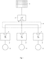
- the Fig. 1 shows the inverter system according to the invention with a rectifier 1 and three inverters 2.
- the rectifier 1 is connected to an AC power source 3, which can be formed for example by the power grid.
- the rectifier 1 rectifies the three-phase alternating current provided by the AC power source 3 and makes it available to the inverters 2 via a DC circuit 4.
- the inverters 2 are connected to electrical consumers 5, which are supplied with energy by the inverters 2.
- the electrical loads 5 may include, for example, DC motors or AC motors.
- the rectifier 1 has a modulation device 6, with which signals the DC circuit 4 can be modulated. About the DC circuit 4, the signals are applied to all three inverters 2.
- the inverters 2 each have a demodulation device 7 with which signals modulated onto the DC circuit 4 can be demodulated.
- the signal transmitted to the inverters 2 via the DC circuit 4 from the rectifier 1 may be, for example, a simple on / off signal used to control the inverters 2, so that when the signal "on” the inverters 2 the respective connected electrical Consumers 5 supply energy and the signal "off” the inverter 2 to the respective connected electrical load 5 is not supplied with energy.
- the electrical loads 5 are formed by electric motors, significantly more complex signals can also be transmitted via the DC circuit 4.
- Fig. 2 illustrated further embodiment of the invention is characterized in comparison to Fig. 1 in particular by further modulation devices 6 and demodulation devices 7.
- Both the rectifier 1 and All three inverters 2 each have a modulation device 6 and a demodulation device 7.
- these four components, the rectifier 1 and the three inverters 2 exchange information with each other by propagating signals through the DC circuit 4. Due to this multiple use of the DC circuit 4, on the one hand for energy transmission and on the other hand for information transmission, costs for separate signal lines for information transmission are saved.
- a DC power consumer 8 is connected directly.
- This DC power consumer 8 takes the DC circuit 4 electrical energy directly in the form of DC.
- a DC-DC converter between the DC circuit 4 and the DC power consumer 8 may be provided to adjust the voltage of the DC circuit 4 to the required input voltage of the DC power consumer 8.
- the DC power consumer has a modulation device and / or a demodulation device. In this way, the DC power consumer 8 can communicate with the other components connected to the DC circuit 4.
- Fig. 2 shown inverter 2 are each connected to a Notenergy Eat 9.
- Notenergy Grande 9 come in particular batteries or capacitors, especially so-called ultracaps, in question.
- the inverters can be supplied, if necessary, with note energy. Such a need may occur, for example, when the AC power source 3 fails or for other reasons, the power supply of the inverter 2 from the DC circuit 4 is no longer guaranteed.
- the energy provided by the note energy stores 9 can be used by the inverters 2 to supply the electrical loads 5 with electrical energy.
- the modulation devices 6 the inverter 2 can modulate signals to the DC circuit 4, the status information on the Note energy storage 9 include such.
Claims (9)
- Système de convertisseur d'un système de pitch d'une installation éolienne dotée d'un convertisseur (1) et au moins deux onduleurs (2), le convertisseur (1) pouvant être alimenté en énergie par une source (3) de courant alternatif, le convertisseur (1) étant connecté, pour l'alimentation en énergie, à chacun des onduleurs via un circuit (4) de courant continu commun et chaque onduleur (2) pouvant être connecté à chaque fois à au moins un consommateur électrique (5) pour l'alimentation en énergie du consommateur (5) respectif ou des consommateurs (5) respectifs,
caractérisé en ce que,
au moins un des onduleurs (2) présente un dispositif de modulation (6) pour moduler un signal sur le circuit (4) de courant continu et en ce que le convertisseur (1) présente un dispositif de démodulation (7) pour démoduler un signal modulé sur le circuit (4) de courant continu ou au moins un autre des onduleurs (2) présente un dispositif de démodulation (7) pour démoduler un signal modulé sur le circuit (4) de courant continu. - Système de convertisseur selon la revendication 1, caractérisé en ce que ledit au moins un onduleur (2) présentant un dispositif de modulation (6) ou un des onduleurs (2) présentant un dispositif de modulation (6) est connecté à un accumulateur de secours (9), des signaux pouvant être modulés sur le circuit (4) de courant continu par le dispositif de modulation (6) dudit au moins un onduleur (2) ou par au moins un des dispositifs de modulation (6) des onduleurs (2), les signaux contenant des informations de statut de l'accumulateur de secours (9) respectif.
- Système de convertisseur selon la revendication 2, caractérisé en ce que les informations de statut modulées sur le circuit (4) de courant continu comprennent au moins une des informations tension, résistance interne, capacité ou température.
- Système de convertisseur selon l'une quelconque des revendications 1 à 3, caractérisé en ce qu'un dispositif de modulation (6) d'au moins un onduleur (2) permet de moduler des signaux sur le circuit (4) de courant continu, les signaux comprenant des informations sur l'onduleur (2) respectif.
- Système de convertisseur selon la revendication 4, caractérisé en ce que les informations sur l'onduleur (2) respectif, modulables sur le circuit (4) de courant continu, comprennent au moins une des informations type d'onduleur, données de configuration ou ID de l'onduleur.
- Système de convertisseur selon l'une quelconque des revendications 1 à 5, caractérisé en ce qu'au moins un consommateur (8) d'énergie à courant continu est connecté au circuit (4) de courant continu, l'énergie électrique nécessaire pour le fonctionnement de ce consommateur (8) d'énergie à courant continu ou de ces plusieurs consommateurs (8) d'énergie à courant continu peut être prélevée directement sous forme de courant continu du circuit (4) de courant continu.
- Procédé pour le fonctionnement d'un système de convertisseur dans un système de pitch d'une installation éolienne, présentant un convertisseur (1) et au moins deux onduleurs (2), le convertisseur (1) étant alimenté en énergie par une source (3) de courant alternatif, le convertisseur (1) étant connecté, pour l'alimentation en énergie, à chacun des onduleurs (2) via un circuit (4) de courant continu commun et chaque onduleur (2) étant connecté à chaque fois à au moins un consommateur électrique (5) pour l'alimentation en énergie du consommateur (5) respectif,
caractérisé en ce que,
au moins un des onduleurs (2) présente un dispositif de modulation (6) pour moduler un signal sur le circuit (4) de courant continu et en ce que le convertisseur (1) présente un dispositif de démodulation (7) pour démoduler un signal modulé sur le circuit de courant continu (4) ou au moins un autre des onduleurs (2) présente un dispositif de démodulation (7) pour démoduler un signal modulé sur le circuit de courant continu (4). - Procédé pour le fonctionnement d'un système de convertisseur selon la revendication 7, caractérisé en ce que ledit au moins un onduleur (2) présentant un dispositif de modulation (6) ou un des onduleurs (2) présentant un dispositif de modulation (6) est connecté à un accumulateur de secours (9), des signaux étant modulés sur le circuit (4) de courant continu par le dispositif de modulation (6) dudit au moins un onduleur (2) ou par au moins un des dispositifs de modulation (6) des onduleurs (2), les signaux contenant des informations de statut de l'accumulateur de secours (9) respectif.
- Procédé pour le fonctionnement d'un système de convertisseur selon l'une quelconque des revendications 7 à 8, caractérisé en ce qu'au moins un consommateur (8) d'énergie à courant continu est connecté au circuit (4) de courant continu, l'énergie électrique nécessaire pour le fonctionnement de ce consommateur (8) d'énergie à courant continu ou de ces plusieurs consommateurs (8) d'énergie à courant continu est prélevée directement sous forme de courant continu du circuit (4) de courant continu.
Priority Applications (3)
| Application Number | Priority Date | Filing Date | Title |
|---|---|---|---|
| ES13186664.2T ES2686933T3 (es) | 2013-09-30 | 2013-09-30 | Sistema de conversión, sistema de inclinación con un sistema de conversión, y método para hacer funcionar un sistema de conversión |
| DK13186664.2T DK2854300T3 (en) | 2013-09-30 | 2013-09-30 | CONVERTER SYSTEM, PITCH SYSTEM WITH A CONVERTER SYSTEM AND PROCEDURE FOR OPERATING A CONVERTER SYSTEM |
| EP13186664.2A EP2854300B1 (fr) | 2013-09-30 | 2013-09-30 | Système de convertisseur, système de pitch doté d'un système de convertisseur et procédé de fonctionnement d'un système de convertisseur |
Applications Claiming Priority (1)
| Application Number | Priority Date | Filing Date | Title |
|---|---|---|---|
| EP13186664.2A EP2854300B1 (fr) | 2013-09-30 | 2013-09-30 | Système de convertisseur, système de pitch doté d'un système de convertisseur et procédé de fonctionnement d'un système de convertisseur |
Publications (2)
| Publication Number | Publication Date |
|---|---|
| EP2854300A1 EP2854300A1 (fr) | 2015-04-01 |
| EP2854300B1 true EP2854300B1 (fr) | 2018-06-20 |
Family
ID=49274485
Family Applications (1)
| Application Number | Title | Priority Date | Filing Date |
|---|---|---|---|
| EP13186664.2A Not-in-force EP2854300B1 (fr) | 2013-09-30 | 2013-09-30 | Système de convertisseur, système de pitch doté d'un système de convertisseur et procédé de fonctionnement d'un système de convertisseur |
Country Status (3)
| Country | Link |
|---|---|
| EP (1) | EP2854300B1 (fr) |
| DK (1) | DK2854300T3 (fr) |
| ES (1) | ES2686933T3 (fr) |
Family Cites Families (8)
| Publication number | Priority date | Publication date | Assignee | Title |
|---|---|---|---|---|
| DE19520596A1 (de) * | 1995-06-06 | 1996-12-12 | Siemens Ag | Anordnung zum Übertragen von Daten und Energie über eine Busleitung |
| US7072407B2 (en) * | 2000-01-31 | 2006-07-04 | Brookline Flolmstead Llc | Combination power and full duplex data cable |
| US7126236B2 (en) | 2005-03-15 | 2006-10-24 | General Electric Company | Methods and apparatus for pitch control power conversion |
| JP2006302733A (ja) * | 2005-04-22 | 2006-11-02 | Matsushita Electric Ind Co Ltd | 電池パック及びその接続システム |
| US7740448B2 (en) | 2005-09-09 | 2010-06-22 | General Electric Company | Pitch control battery backup methods and system |
| EP2326026A1 (fr) * | 2009-11-19 | 2011-05-25 | Thales | Système à courants porteurs en ligne à bus d'énergie à courant continu. |
| KR20110121187A (ko) * | 2010-04-30 | 2011-11-07 | 최인숙 | 전력선 통신기능을 가지는 옥내 직류전력 시스템 |
| JP5444304B2 (ja) * | 2011-10-25 | 2014-03-19 | ファナック株式会社 | 無効電流指令作成部を有するモータ駆動装置 |
-
2013
- 2013-09-30 ES ES13186664.2T patent/ES2686933T3/es active Active
- 2013-09-30 EP EP13186664.2A patent/EP2854300B1/fr not_active Not-in-force
- 2013-09-30 DK DK13186664.2T patent/DK2854300T3/en active
Non-Patent Citations (1)
| Title |
|---|
| None * |
Also Published As
| Publication number | Publication date |
|---|---|
| ES2686933T3 (es) | 2018-10-22 |
| DK2854300T3 (en) | 2018-09-03 |
| EP2854300A1 (fr) | 2015-04-01 |
Similar Documents
| Publication | Publication Date | Title |
|---|---|---|
| EP2578876B1 (fr) | Système de pas pour une éolienne et procédé de fonctionnement d'un système de pas | |
| DE102010024234A1 (de) | Sicherheitsgerät und Leistungsumformer | |
| DE102017107355B4 (de) | Stromrichteranordnung zur Speisung von Fahrzeugen und Anlage hiermit | |
| DE102011121707A1 (de) | Elektrisches System für ein Luftfahrzeug | |
| WO2015135938A1 (fr) | Dispositif et procédé de commutation d'un système de gestion de batterie | |
| DE102014212553B3 (de) | Modulares Türantriebssteuerungssystem sowie modulares Türantriebssystem | |
| EP2614576B1 (fr) | Système local de distribution d'énergie comportant un circuit intermédiaire | |
| EP2736159B1 (fr) | Système de convertisseur et installation éolienne ou hydraulique | |
| EP2071693A2 (fr) | Procédé et circuit destinés à la commande de l'alimentation en énergie de plusieurs onduleurs monophasés dans un réseau multiphases | |
| EP2854300B1 (fr) | Système de convertisseur, système de pitch doté d'un système de convertisseur et procédé de fonctionnement d'un système de convertisseur | |
| WO2011033027A2 (fr) | Circuit doté d'une partie onduleur comprenant une unité de commande centrale | |
| EP2579690A2 (fr) | Système d'éclairage pour aéroport | |
| EP2713470A1 (fr) | Circuit doté d'un convertisseur de courant résonant et procédé de fonctionnement d'un convertisseur de courant résonant | |
| EP2426431A2 (fr) | Système de suivi en fonction de la position du soleil de modules de cellules solaires | |
| EP2530809A2 (fr) | Commutation d'alimentation électrique et procédé de préparation d'une tension d'alimentation | |
| DE102008027887A1 (de) | Verfahren und Schaltungsanordnung zum Steuern der Energieeinspeisung von mehreren einphasigen Wechselrichtern in ein Mehrphasennetz | |
| DE102015012358A1 (de) | Stromversorgungssystem eines Kraftfahrzeugs, Kraftfahrzeug sowie Verfahren zum Betrieb eines Stromversorgungssystems | |
| EP3624290A1 (fr) | Procédé et dispositif de commande destiné au fonctionnement d'un réseau de distribution d'énergie électrique | |
| EP3197726B1 (fr) | Réseau de bord | |
| DE102009056949B4 (de) | Verfahren zur Energieversorgung eines autonomen Sensormoduls | |
| DE102018132187A1 (de) | Verfahren, Vorrichtung und Fortbewegungsmittel zum Ermitteln einer Qualität eines Stromnetzes durch ein Fortbewegungsmittel | |
| DE102011009933B4 (de) | Elektrofahrzeug und Verfahren zum Betreiben eines Elektrofahrzeugs | |
| WO2012163731A2 (fr) | Procédé de fonctionnement d'un générateur dans un réseau électrique et réseau électrique comprenant un générateur de ce type | |
| DE202017102254U1 (de) | Leistungsversorgungsanordnung | |
| EP3721548B1 (fr) | Système photovoltaïque et onduleur doté d'une interface de communication |
Legal Events
| Date | Code | Title | Description |
|---|---|---|---|
| PUAI | Public reference made under article 153(3) epc to a published international application that has entered the european phase |
Free format text: ORIGINAL CODE: 0009012 |
|
| 17P | Request for examination filed |
Effective date: 20130930 |
|
| AK | Designated contracting states |
Kind code of ref document: A1 Designated state(s): AL AT BE BG CH CY CZ DE DK EE ES FI FR GB GR HR HU IE IS IT LI LT LU LV MC MK MT NL NO PL PT RO RS SE SI SK SM TR |
|
| AX | Request for extension of the european patent |
Extension state: BA ME |
|
| R17P | Request for examination filed (corrected) |
Effective date: 20150930 |
|
| RBV | Designated contracting states (corrected) |
Designated state(s): AL AT BE BG CH CY CZ DE DK EE ES FI FR GB GR HR HU IE IS IT LI LT LU LV MC MK MT NL NO PL PT RO RS SE SI SK SM TR |
|
| GRAP | Despatch of communication of intention to grant a patent |
Free format text: ORIGINAL CODE: EPIDOSNIGR1 |
|
| RIC1 | Information provided on ipc code assigned before grant |
Ipc: H02M 5/40 20060101ALI20171206BHEP Ipc: H02J 7/34 20060101ALN20171206BHEP Ipc: H04B 3/54 20060101AFI20171206BHEP Ipc: H02J 9/00 20060101ALN20171206BHEP |
|
| RIC1 | Information provided on ipc code assigned before grant |
Ipc: H04B 3/54 20060101AFI20171208BHEP Ipc: H02J 9/00 20060101ALN20171208BHEP Ipc: H02J 7/34 20060101ALN20171208BHEP Ipc: H02M 5/40 20060101ALI20171208BHEP |
|
| INTG | Intention to grant announced |
Effective date: 20180109 |
|
| GRAS | Grant fee paid |
Free format text: ORIGINAL CODE: EPIDOSNIGR3 |
|
| GRAA | (expected) grant |
Free format text: ORIGINAL CODE: 0009210 |
|
| AK | Designated contracting states |
Kind code of ref document: B1 Designated state(s): AL AT BE BG CH CY CZ DE DK EE ES FI FR GB GR HR HU IE IS IT LI LT LU LV MC MK MT NL NO PL PT RO RS SE SI SK SM TR |
|
| REG | Reference to a national code |
Ref country code: GB Ref legal event code: FG4D Free format text: NOT ENGLISH |
|
| REG | Reference to a national code |
Ref country code: IE Ref legal event code: FG4D Free format text: LANGUAGE OF EP DOCUMENT: GERMAN |
|
| REG | Reference to a national code |
Ref country code: AT Ref legal event code: REF Ref document number: 1011294 Country of ref document: AT Kind code of ref document: T Effective date: 20180715 |
|
| REG | Reference to a national code |
Ref country code: DE Ref legal event code: R096 Ref document number: 502013010418 Country of ref document: DE |
|
| REG | Reference to a national code |
Ref country code: DK Ref legal event code: T3 Effective date: 20180828 |
|
| REG | Reference to a national code |
Ref country code: ES Ref legal event code: FG2A Ref document number: 2686933 Country of ref document: ES Kind code of ref document: T3 Effective date: 20181022 |
|
| REG | Reference to a national code |
Ref country code: NL Ref legal event code: MP Effective date: 20180620 |
|
| PG25 | Lapsed in a contracting state [announced via postgrant information from national office to epo] |
Ref country code: NO Free format text: LAPSE BECAUSE OF FAILURE TO SUBMIT A TRANSLATION OF THE DESCRIPTION OR TO PAY THE FEE WITHIN THE PRESCRIBED TIME-LIMIT Effective date: 20180920 Ref country code: LT Free format text: LAPSE BECAUSE OF FAILURE TO SUBMIT A TRANSLATION OF THE DESCRIPTION OR TO PAY THE FEE WITHIN THE PRESCRIBED TIME-LIMIT Effective date: 20180620 Ref country code: SE Free format text: LAPSE BECAUSE OF FAILURE TO SUBMIT A TRANSLATION OF THE DESCRIPTION OR TO PAY THE FEE WITHIN THE PRESCRIBED TIME-LIMIT Effective date: 20180620 Ref country code: FI Free format text: LAPSE BECAUSE OF FAILURE TO SUBMIT A TRANSLATION OF THE DESCRIPTION OR TO PAY THE FEE WITHIN THE PRESCRIBED TIME-LIMIT Effective date: 20180620 Ref country code: BG Free format text: LAPSE BECAUSE OF FAILURE TO SUBMIT A TRANSLATION OF THE DESCRIPTION OR TO PAY THE FEE WITHIN THE PRESCRIBED TIME-LIMIT Effective date: 20180920 |
|
| PGFP | Annual fee paid to national office [announced via postgrant information from national office to epo] |
Ref country code: DE Payment date: 20180920 Year of fee payment: 6 |
|
| REG | Reference to a national code |
Ref country code: LT Ref legal event code: MG4D |
|
| PG25 | Lapsed in a contracting state [announced via postgrant information from national office to epo] |
Ref country code: LV Free format text: LAPSE BECAUSE OF FAILURE TO SUBMIT A TRANSLATION OF THE DESCRIPTION OR TO PAY THE FEE WITHIN THE PRESCRIBED TIME-LIMIT Effective date: 20180620 Ref country code: RS Free format text: LAPSE BECAUSE OF FAILURE TO SUBMIT A TRANSLATION OF THE DESCRIPTION OR TO PAY THE FEE WITHIN THE PRESCRIBED TIME-LIMIT Effective date: 20180620 Ref country code: GR Free format text: LAPSE BECAUSE OF FAILURE TO SUBMIT A TRANSLATION OF THE DESCRIPTION OR TO PAY THE FEE WITHIN THE PRESCRIBED TIME-LIMIT Effective date: 20180921 Ref country code: HR Free format text: LAPSE BECAUSE OF FAILURE TO SUBMIT A TRANSLATION OF THE DESCRIPTION OR TO PAY THE FEE WITHIN THE PRESCRIBED TIME-LIMIT Effective date: 20180620 |
|
| PGFP | Annual fee paid to national office [announced via postgrant information from national office to epo] |
Ref country code: DK Payment date: 20180921 Year of fee payment: 6 |
|
| PG25 | Lapsed in a contracting state [announced via postgrant information from national office to epo] |
Ref country code: NL Free format text: LAPSE BECAUSE OF FAILURE TO SUBMIT A TRANSLATION OF THE DESCRIPTION OR TO PAY THE FEE WITHIN THE PRESCRIBED TIME-LIMIT Effective date: 20180620 |
|
| PG25 | Lapsed in a contracting state [announced via postgrant information from national office to epo] |
Ref country code: EE Free format text: LAPSE BECAUSE OF FAILURE TO SUBMIT A TRANSLATION OF THE DESCRIPTION OR TO PAY THE FEE WITHIN THE PRESCRIBED TIME-LIMIT Effective date: 20180620 Ref country code: PL Free format text: LAPSE BECAUSE OF FAILURE TO SUBMIT A TRANSLATION OF THE DESCRIPTION OR TO PAY THE FEE WITHIN THE PRESCRIBED TIME-LIMIT Effective date: 20180620 Ref country code: IS Free format text: LAPSE BECAUSE OF FAILURE TO SUBMIT A TRANSLATION OF THE DESCRIPTION OR TO PAY THE FEE WITHIN THE PRESCRIBED TIME-LIMIT Effective date: 20181020 Ref country code: SK Free format text: LAPSE BECAUSE OF FAILURE TO SUBMIT A TRANSLATION OF THE DESCRIPTION OR TO PAY THE FEE WITHIN THE PRESCRIBED TIME-LIMIT Effective date: 20180620 Ref country code: CZ Free format text: LAPSE BECAUSE OF FAILURE TO SUBMIT A TRANSLATION OF THE DESCRIPTION OR TO PAY THE FEE WITHIN THE PRESCRIBED TIME-LIMIT Effective date: 20180620 Ref country code: RO Free format text: LAPSE BECAUSE OF FAILURE TO SUBMIT A TRANSLATION OF THE DESCRIPTION OR TO PAY THE FEE WITHIN THE PRESCRIBED TIME-LIMIT Effective date: 20180620 |
|
| PG25 | Lapsed in a contracting state [announced via postgrant information from national office to epo] |
Ref country code: IT Free format text: LAPSE BECAUSE OF FAILURE TO SUBMIT A TRANSLATION OF THE DESCRIPTION OR TO PAY THE FEE WITHIN THE PRESCRIBED TIME-LIMIT Effective date: 20180620 Ref country code: SM Free format text: LAPSE BECAUSE OF FAILURE TO SUBMIT A TRANSLATION OF THE DESCRIPTION OR TO PAY THE FEE WITHIN THE PRESCRIBED TIME-LIMIT Effective date: 20180620 |
|
| PGFP | Annual fee paid to national office [announced via postgrant information from national office to epo] |
Ref country code: ES Payment date: 20181023 Year of fee payment: 6 |
|
| REG | Reference to a national code |
Ref country code: DE Ref legal event code: R097 Ref document number: 502013010418 Country of ref document: DE |
|
| PLBE | No opposition filed within time limit |
Free format text: ORIGINAL CODE: 0009261 |
|
| STAA | Information on the status of an ep patent application or granted ep patent |
Free format text: STATUS: NO OPPOSITION FILED WITHIN TIME LIMIT |
|
| PG25 | Lapsed in a contracting state [announced via postgrant information from national office to epo] |
Ref country code: MC Free format text: LAPSE BECAUSE OF FAILURE TO SUBMIT A TRANSLATION OF THE DESCRIPTION OR TO PAY THE FEE WITHIN THE PRESCRIBED TIME-LIMIT Effective date: 20180620 |
|
| REG | Reference to a national code |
Ref country code: CH Ref legal event code: PL |
|
| GBPC | Gb: european patent ceased through non-payment of renewal fee |
Effective date: 20180930 |
|
| 26N | No opposition filed |
Effective date: 20190321 |
|
| REG | Reference to a national code |
Ref country code: BE Ref legal event code: MM Effective date: 20180930 |
|
| REG | Reference to a national code |
Ref country code: IE Ref legal event code: MM4A |
|
| PG25 | Lapsed in a contracting state [announced via postgrant information from national office to epo] |
Ref country code: LU Free format text: LAPSE BECAUSE OF NON-PAYMENT OF DUE FEES Effective date: 20180930 |
|
| PG25 | Lapsed in a contracting state [announced via postgrant information from national office to epo] |
Ref country code: IE Free format text: LAPSE BECAUSE OF NON-PAYMENT OF DUE FEES Effective date: 20180930 |
|
| PG25 | Lapsed in a contracting state [announced via postgrant information from national office to epo] |
Ref country code: SI Free format text: LAPSE BECAUSE OF FAILURE TO SUBMIT A TRANSLATION OF THE DESCRIPTION OR TO PAY THE FEE WITHIN THE PRESCRIBED TIME-LIMIT Effective date: 20180620 Ref country code: BE Free format text: LAPSE BECAUSE OF NON-PAYMENT OF DUE FEES Effective date: 20180930 Ref country code: CH Free format text: LAPSE BECAUSE OF NON-PAYMENT OF DUE FEES Effective date: 20180930 Ref country code: LI Free format text: LAPSE BECAUSE OF NON-PAYMENT OF DUE FEES Effective date: 20180930 Ref country code: FR Free format text: LAPSE BECAUSE OF NON-PAYMENT OF DUE FEES Effective date: 20180930 |
|
| PG25 | Lapsed in a contracting state [announced via postgrant information from national office to epo] |
Ref country code: GB Free format text: LAPSE BECAUSE OF NON-PAYMENT OF DUE FEES Effective date: 20180930 |
|
| REG | Reference to a national code |
Ref country code: AT Ref legal event code: MM01 Ref document number: 1011294 Country of ref document: AT Kind code of ref document: T Effective date: 20180930 |
|
| PG25 | Lapsed in a contracting state [announced via postgrant information from national office to epo] |
Ref country code: AL Free format text: LAPSE BECAUSE OF FAILURE TO SUBMIT A TRANSLATION OF THE DESCRIPTION OR TO PAY THE FEE WITHIN THE PRESCRIBED TIME-LIMIT Effective date: 20180620 |
|
| PG25 | Lapsed in a contracting state [announced via postgrant information from national office to epo] |
Ref country code: AT Free format text: LAPSE BECAUSE OF NON-PAYMENT OF DUE FEES Effective date: 20180930 Ref country code: MT Free format text: LAPSE BECAUSE OF FAILURE TO SUBMIT A TRANSLATION OF THE DESCRIPTION OR TO PAY THE FEE WITHIN THE PRESCRIBED TIME-LIMIT Effective date: 20180620 |
|
| PG25 | Lapsed in a contracting state [announced via postgrant information from national office to epo] |
Ref country code: TR Free format text: LAPSE BECAUSE OF FAILURE TO SUBMIT A TRANSLATION OF THE DESCRIPTION OR TO PAY THE FEE WITHIN THE PRESCRIBED TIME-LIMIT Effective date: 20180620 |
|
| REG | Reference to a national code |
Ref country code: DE Ref legal event code: R119 Ref document number: 502013010418 Country of ref document: DE |
|
| REG | Reference to a national code |
Ref country code: DK Ref legal event code: EBP Effective date: 20190930 |
|
| PG25 | Lapsed in a contracting state [announced via postgrant information from national office to epo] |
Ref country code: PT Free format text: LAPSE BECAUSE OF FAILURE TO SUBMIT A TRANSLATION OF THE DESCRIPTION OR TO PAY THE FEE WITHIN THE PRESCRIBED TIME-LIMIT Effective date: 20180620 Ref country code: HU Free format text: LAPSE BECAUSE OF FAILURE TO SUBMIT A TRANSLATION OF THE DESCRIPTION OR TO PAY THE FEE WITHIN THE PRESCRIBED TIME-LIMIT; INVALID AB INITIO Effective date: 20130930 |
|
| PG25 | Lapsed in a contracting state [announced via postgrant information from national office to epo] |
Ref country code: MK Free format text: LAPSE BECAUSE OF NON-PAYMENT OF DUE FEES Effective date: 20180620 Ref country code: CY Free format text: LAPSE BECAUSE OF FAILURE TO SUBMIT A TRANSLATION OF THE DESCRIPTION OR TO PAY THE FEE WITHIN THE PRESCRIBED TIME-LIMIT Effective date: 20180620 |
|
| PG25 | Lapsed in a contracting state [announced via postgrant information from national office to epo] |
Ref country code: DE Free format text: LAPSE BECAUSE OF NON-PAYMENT OF DUE FEES Effective date: 20200401 |
|
| PG25 | Lapsed in a contracting state [announced via postgrant information from national office to epo] |
Ref country code: DK Free format text: LAPSE BECAUSE OF NON-PAYMENT OF DUE FEES Effective date: 20190930 |
|
| REG | Reference to a national code |
Ref country code: ES Ref legal event code: FD2A Effective date: 20210201 |
|
| PG25 | Lapsed in a contracting state [announced via postgrant information from national office to epo] |
Ref country code: ES Free format text: LAPSE BECAUSE OF NON-PAYMENT OF DUE FEES Effective date: 20191001 |