EP2854300B1 - Converter system, pitch system with a converter system and method for operating a converter system - Google Patents
Converter system, pitch system with a converter system and method for operating a converter system Download PDFInfo
- Publication number
- EP2854300B1 EP2854300B1 EP13186664.2A EP13186664A EP2854300B1 EP 2854300 B1 EP2854300 B1 EP 2854300B1 EP 13186664 A EP13186664 A EP 13186664A EP 2854300 B1 EP2854300 B1 EP 2854300B1
- Authority
- EP
- European Patent Office
- Prior art keywords
- direct current
- inverter
- inverters
- power
- circuit
- Prior art date
- Legal status (The legal status is an assumption and is not a legal conclusion. Google has not performed a legal analysis and makes no representation as to the accuracy of the status listed.)
- Not-in-force
Links
Images

Classifications
-
- H—ELECTRICITY
- H02—GENERATION; CONVERSION OR DISTRIBUTION OF ELECTRIC POWER
- H02M—APPARATUS FOR CONVERSION BETWEEN AC AND AC, BETWEEN AC AND DC, OR BETWEEN DC AND DC, AND FOR USE WITH MAINS OR SIMILAR POWER SUPPLY SYSTEMS; CONVERSION OF DC OR AC INPUT POWER INTO SURGE OUTPUT POWER; CONTROL OR REGULATION THEREOF
- H02M5/00—Conversion of ac power input into ac power output, e.g. for change of voltage, for change of frequency, for change of number of phases
- H02M5/40—Conversion of ac power input into ac power output, e.g. for change of voltage, for change of frequency, for change of number of phases with intermediate conversion into dc
-
- H—ELECTRICITY
- H04—ELECTRIC COMMUNICATION TECHNIQUE
- H04B—TRANSMISSION
- H04B3/00—Line transmission systems
- H04B3/54—Systems for transmission via power distribution lines
- H04B3/548—Systems for transmission via power distribution lines the power on the line being DC
-
- H—ELECTRICITY
- H02—GENERATION; CONVERSION OR DISTRIBUTION OF ELECTRIC POWER
- H02J—CIRCUIT ARRANGEMENTS OR SYSTEMS FOR SUPPLYING OR DISTRIBUTING ELECTRIC POWER; SYSTEMS FOR STORING ELECTRIC ENERGY
- H02J7/00—Circuit arrangements for charging or depolarising batteries or for supplying loads from batteries
- H02J7/34—Parallel operation in networks using both storage and other dc sources, e.g. providing buffering
-
- H—ELECTRICITY
- H02—GENERATION; CONVERSION OR DISTRIBUTION OF ELECTRIC POWER
- H02J—CIRCUIT ARRANGEMENTS OR SYSTEMS FOR SUPPLYING OR DISTRIBUTING ELECTRIC POWER; SYSTEMS FOR STORING ELECTRIC ENERGY
- H02J9/00—Circuit arrangements for emergency or stand-by power supply, e.g. for emergency lighting
Definitions
- the invention relates to an inverter system having a rectifier and at least two inverters, wherein the rectifier is powered by an AC power source, the rectifier is connected to each of the inverters for power supply via a common DC circuit and each inverter, each with at least one electrical load to power the respective consumer or the respective consumer is connectable.
- Such a converter system serves to supply power to a plurality of electrical consumers from an AC power source.
- the AC power source may be, for example, the utility grid or a generator.
- the rectifier By the rectifier, the AC voltage provided by the AC power source is rectified into a DC voltage. This DC voltage is fed into the common DC circuit.
- the terms DC circuit and DC link are common and can be used synonymously.
- the inverters can remove electrical energy from the DC circuit and operate electrical consumers with this electrical energy.
- the US 7,126,236 B2 discloses a method and system for powering at least one DC motor of a wind turbine, the system comprising a bridge rectifier connected to a power source for generating a DC voltage and providing it to the at least one DC motor and a DC link capacitor the DC voltage smoothes and acts as an energy storage and energy source for the at least one DC motor. Further, it is disclosed that a plurality of DC motors are used, which are powered by separate drive systems, wherein the intermediate circuits of these drive systems are interconnected, so that energy can be exchanged between these intermediate circuits.
- the US 7,740,448 B2 discloses an apparatus for controlling the angle of attack of a rotor blade of a wind turbine, the apparatus comprising: a pitch control system comprising a MOSFET based power converter; a DC circuit having a DC circuit capacitor and being configured to supply power to the pitch control system through the MOSFET based power converter; a source of AC input power for supplying power to the DC circuit; and a backup battery configured to not supply power to the DC circuit when full AC input power is available; and further wherein the apparatus is configured to: use energy stored in the dc capacitor to supply power to the pitch control system during a loss or incursion of ac input power through the mosfet based power converter; and to maintain charge on the dc circuit capacitor using the backup battery as soon as the voltage across the dc circuit capacitor drops while supplying power to the gating control system; wherein the AC source is a non-regenerative source, and the DC circuit is common to a plurality of pitch motor systems; and further wherein maintaining charge on the
- an engine assembly that includes a converter, an inverter, a voltage detector and a numerical controller.
- the converter converts an input AC voltage into a DC current and the inverter converts the DC current of the converter into an AC current for driving an electric motor.
- the voltage detector monitors the voltage on the DC side and increases the power consumption of the electric motor when the monitored voltage exceeds a predetermined limit.
- DE 195 20 596 A1 discloses an arrangement for transmitting data and energy, which has two bus lines to improve reliability, wherein the first bus line, a DC line and the second Bus line is either a DC or AC line.
- the prerequisite for this type of fail-safe communication is that when using a DC bus and an AC power line the communicating devices must be configured so that they can be supplied with either direct current or alternating current.
- WO 2011/136591 A2 is known for indoors suitable DC power supply system, which can be coupled by means of rectifiers AC-powered devices to the DC power supply system.
- the AC devices have AC side modulators / demodulators which allow communication of the AC devices via the DC power supply system.
- the invention further relates to a pitch system of a wind turbine with a Umrichtersytem and a method for operating an inverter system with a rectifier and at least two inverters, wherein the rectifier is powered by an AC power source, the rectifier for power supply to each of the inverters connected via a common DC circuit is and each inverter is connected to a respective electrical consumer for supplying energy to the respective consumer.
- the previously derived and indicated object is achieved on the basis of the converter system described above in that the rectifier has a modulation device in order to modulate a signal to the DC circuit, wherein at least one of the inverters has a demodulation device for demodulating a signal modulated onto the DC circuit.
- the rectifier can modulate a signal to the DC circuit and transmit this signal via the DC circuit to the inverters.
- the modulation can be done in different ways.
- the DC voltage generated by the rectifier can be superimposed on a voltage signal.
- the voltage signal may in this case for example have an amplitude modulation or an angle modulation, such as a phase or frequency modulation.
- Mixed forms, such as vector modulation, are also conceivable.
- Digital modulation techniques such as In particular, the pulse width modulation or the pulse-code modulation can also be used.
- the signal modulated onto the DC circuit can be demodulated and reused by the inverter.
- the demodulated signal can in particular be used to control or regulate an electrical consumer connected to the inverter. This can be done, for example, by the fact that the signal is used by the inverter to specifically supply the electrical consumer with energy. This means in particular that the signal controls or regulates the electrical load indirectly via the power supply by the inverter.
- At least one of the consumers is an AC motor or a DC motor.
- both AC motors and DC motors can be operated by the inverters.
- the term "inverter” also encompasses a family of components which can generate a voltage of any frequency and phase and thus both DC voltage and AC voltage from a DC voltage applied to the input of the inverter.
- An example of this are bridge inverters with semiconductor switching elements.
- At least one of the inverters has a modulation device in order to choirmodulieren a signal to the DC circuit. If one of the Inverter has a modulation device, it can modulate a signal to the DC circuit with this modulation device. This signal, if another inverter has a demodulation device, can be demodulated by this demodulation device. In this way, the individual inverters can communicate with each other. It is particularly advantageous if all inverters have both a modulation device and a demodulation device.
- An advantageous embodiment of the invention is characterized in that the rectifier has a demodulation device in order to demodulate a signal modulated onto the DC circuit.
- the rectifier can demodulate a signal modulated onto the DC circuit. This allows transmission of information not only from the rectifier to the inverters, but also vice versa, from the inverters to the rectifiers.
- the rectifier can also use its demodulation device for self-diagnosis by demodulating the signal it has itself modulated on the DC circuit and comparing it with the original signal. This functionality is independent of whether one of the inverters has a modulation device.
- At least one of the modulation device having inverter or one of a modulation device having inverter is connected to a Notenergy Grande, wherein modulated by the modulation device of the at least one inverter or by at least one of the modulation devices of the inverter signals the DC circuit are, wherein the signals include status information of the respective Not energie réelles.
- the note energy store can each be connected directly to this DC link capacitor and thus serve as an extension of the DC link capacitor.
- the note energy storage can each directly with the DC link of the respective Inverter be connected.
- the Notenergy Eats replaces the DC link capacitor and is advantageously arranged outside of the inverter.
- the status information which can be modulated onto the DC circuit comprises at least one of the information voltage, internal resistance, capacitance or temperature.
- Prior art drive systems often include note energy storage which, in certain cases, provides the inverter system or special components of the drive system with emergency power, for example, when the AC power source fails. Since such converter systems are often safety-relevant, it is necessary to monitor the Notenergie Eat to quickly detect a failure of the Not energie Grande or even predict. The transmission of the information necessary for this purpose can be carried out according to the invention via the DC circuit.
- status information of the respective Not energieurss which are obtained for example by dedicated sensors, modulated in the form of a signal through the modulation device to the DC circuit.
- This signal can then be demodulated by a demodulation device of the rectifier and / or another inverter.
- the information thus obtained can be forwarded, for example, to a higher-level control device or processed directly.
- a modulation device of at least one inverter the DC circuit signals are modulated, wherein the signals include information about the respective inverter.
- the information about the respective inverter which can be modulated onto the DC circuit comprises at least one of the information inverter type, configuration data or inverter ID.
- the connected gelator and / or other connected inverters may be necessary for the connected gelator and / or other connected inverters to have information about the inverter.
- the connected gelator and / or other connected inverters may be necessary for the connected gelator and / or other connected inverters to have information about the inverter.
- the connected gelator and / or other connected inverters can For example, if one or more inverters are replaced and replaced by another type. In such a case, it is advantageous to transmit this information to the other components of the converter system.
- the transmission of this necessary information can be carried out according to the invention via the DC circuit.
- information about the respective inverter in the form of a signal modulated by the modulation device to the DC circuit. This signal can then be demodulated by a demodulation device of the rectifier and / or another inverter.
- At least one DC power consumer is connected to the DC circuit, through which a DC power consumer or through these multiple DC power consumers the electrical energy necessary for their operation is directly removed as a DC current to the DC circuit.
- DC power consumers from the DC circuit can also be supplied with electrical energy. It is advantageous if these DC energy consumers have a demodulation device and / or a modulation device in order to demodulate signals modulated onto the DC circuit or to modulate signals to the DC circuit. In this way, DC power consumers can communicate with the other components of the drive system. In particular, sensors come as a DC power consumers in question.
- the pitch system comprises an inverter system according to one of claims 1 to 8.
- Pitch systems regulate the position of the blades in a wind turbine by turning the blades around their longitudinal axis.
- An inventive pitch system has the advantage that it is particularly cost-effective and robust.
- the previously derived and indicated object is achieved on the basis of the method described above for operating an inverter system in that the rectifier comprises a modulation device and the DC circuit modulates a signal, wherein at least one of the inverters comprises a demodulation device and demodulates a signal modulated on the DC circuit signal.
- the rectifier modulates a signal to the DC circuit and this signal is transmitted via the DC circuit to the inverters.
- the demodulation device of an inverter demodulates the signal modulated on the DC circuit. In this way, a robust information transfer from the rectifier to an inverter can be cost-effective.
- At least one of the inverters has a modulation device and modulates a signal on the DC circuit. This allows information about the DC circuit to be transferred directly from one inverter to another of the inverters.
- An advantageous embodiment of the invention is characterized in that the rectifier has a demodulation device and demodulates a modulated signal to the DC circuit.
- the rectifier can demodulate its own signal, which it has previously modulated on the DC circuit, for self-diagnostic purposes by means of its demodulation device, or it can receive signals from the inverters, thereby enabling communication in both directions, ie from the rectifier to the inverters and vice versa ,
- At least one of the modulation device having inverter or one of a modulation device having inverter is connected to a Notenergy Grande, wherein by the modulation device of the at least one inverter or by at least one of the modulation devices of the inverter signals be modulated on the DC circuit, wherein the signals include status information of the respective note energy storage.
- the status information is modulated as a signal to the DC circuit by the modulation device of the inverter and then demodulated by a demodulation device of the rectifier and / or another inverter.
- At least one DC power consumer is connected to the DC circuit, which is taken by this one DC power consumers or through these multiple DC power consumers, the electrical energy necessary for their operation directly as DC the DC circuit.
- DC power consumers can be connected to the DC circuit without the interposition of an inverter. These direct current consumers draw the electrical energy necessary for their operation directly as DC voltage from the DC circuit. It is advantageous if these DC energy consumers have a demodulation device and / or a modulation device in order to demodulate signals modulated onto the DC circuit or to modulate signals to the DC circuit. In this way, DC power consumers can communicate with the other components of the drive system.
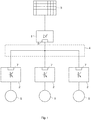
- the Fig. 1 shows the inverter system according to the invention with a rectifier 1 and three inverters 2.
- the rectifier 1 is connected to an AC power source 3, which can be formed for example by the power grid.
- the rectifier 1 rectifies the three-phase alternating current provided by the AC power source 3 and makes it available to the inverters 2 via a DC circuit 4.
- the inverters 2 are connected to electrical consumers 5, which are supplied with energy by the inverters 2.
- the electrical loads 5 may include, for example, DC motors or AC motors.
- the rectifier 1 has a modulation device 6, with which signals the DC circuit 4 can be modulated. About the DC circuit 4, the signals are applied to all three inverters 2.
- the inverters 2 each have a demodulation device 7 with which signals modulated onto the DC circuit 4 can be demodulated.
- the signal transmitted to the inverters 2 via the DC circuit 4 from the rectifier 1 may be, for example, a simple on / off signal used to control the inverters 2, so that when the signal "on” the inverters 2 the respective connected electrical Consumers 5 supply energy and the signal "off” the inverter 2 to the respective connected electrical load 5 is not supplied with energy.
- the electrical loads 5 are formed by electric motors, significantly more complex signals can also be transmitted via the DC circuit 4.
- Fig. 2 illustrated further embodiment of the invention is characterized in comparison to Fig. 1 in particular by further modulation devices 6 and demodulation devices 7.
- Both the rectifier 1 and All three inverters 2 each have a modulation device 6 and a demodulation device 7.
- these four components, the rectifier 1 and the three inverters 2 exchange information with each other by propagating signals through the DC circuit 4. Due to this multiple use of the DC circuit 4, on the one hand for energy transmission and on the other hand for information transmission, costs for separate signal lines for information transmission are saved.
- a DC power consumer 8 is connected directly.
- This DC power consumer 8 takes the DC circuit 4 electrical energy directly in the form of DC.
- a DC-DC converter between the DC circuit 4 and the DC power consumer 8 may be provided to adjust the voltage of the DC circuit 4 to the required input voltage of the DC power consumer 8.
- the DC power consumer has a modulation device and / or a demodulation device. In this way, the DC power consumer 8 can communicate with the other components connected to the DC circuit 4.
- Fig. 2 shown inverter 2 are each connected to a Notenergy Eat 9.
- Notenergy Grande 9 come in particular batteries or capacitors, especially so-called ultracaps, in question.
- the inverters can be supplied, if necessary, with note energy. Such a need may occur, for example, when the AC power source 3 fails or for other reasons, the power supply of the inverter 2 from the DC circuit 4 is no longer guaranteed.
- the energy provided by the note energy stores 9 can be used by the inverters 2 to supply the electrical loads 5 with electrical energy.
- the modulation devices 6 the inverter 2 can modulate signals to the DC circuit 4, the status information on the Note energy storage 9 include such.
Description
Die Erfindung betrifft ein Umrichtersystem mit einem Gleichrichter und wenigstens zwei Wechselrichtern, wobei der Gleichrichter von einer Wechselstromquelle mit Energie versorgbar ist, der Gleichrichter zur Energieversorgung mit jedem der Wechselrichter über einen gemeinsamen Gleichstromkreis verbunden ist und jeder Wechselrichter mit jeweils mindestens einem elektrischen Verbraucher zur Energieversorgung des jeweiligen Verbrauchers oder der jeweiligen Verbraucher verbindbar ist.The invention relates to an inverter system having a rectifier and at least two inverters, wherein the rectifier is powered by an AC power source, the rectifier is connected to each of the inverters for power supply via a common DC circuit and each inverter, each with at least one electrical load to power the respective consumer or the respective consumer is connectable.
Ein derartiges Umrichtersystem dient der Energieversorgung mehrerer elektrischer Verbraucher aus einer Wechselstromquelle. Die Wechselstromquelle kann zum Beispiel das allgemeine Stromnetz oder ein Generator sein. Durch den Gleichrichter wird die durch die Wechselstromquelle bereitgestellte Wechselspannung in eine Gleichspannung gleichgerichtet. Diese Gleichspannung wird in den gemeinsamen Gleichstromkreis gespeist. An Stelle des Begriffs Gleichstromkreis sind auch die Bezeichnungen Gleichspannungskreis und DC-Link üblich und können synonym verwendet werden. Die Wechselrichter können dem Gleichstromkreis elektrische Energie entnehmen und mit dieser elektrischen Energie elektrische Verbraucher betreiben.Such a converter system serves to supply power to a plurality of electrical consumers from an AC power source. The AC power source may be, for example, the utility grid or a generator. By the rectifier, the AC voltage provided by the AC power source is rectified into a DC voltage. This DC voltage is fed into the common DC circuit. In place of the term DC circuit, the terms DC circuit and DC link are common and can be used synonymously. The inverters can remove electrical energy from the DC circuit and operate electrical consumers with this electrical energy.
Die
Die
Aus
Aus
Ein anderes System zur Kommunikation über eine Gleichstromversorgung ist auf dem Gebiet der Satellitentechnik, beziehungsweise Fahrzeugtechnik aus
Die aus dem Stand der Technik bekannten Umrichtersysteme weisen den Nachteil auf, dass zur Informationsübertragung zwischen Gleichrichter und den Wechselrichtern stets separate Signalleitungen verwendet werden müssen. Dies erhöht durch die zusätzlich notwendigen Signalleitungen die Kosten des Umrichtersystems. Ferner ist die Produktion des Umrichtersystems aufwändiger, da die separaten Signalleitungen einen höheren Montageaufwand nach sich ziehen. Da diese Signalleitungen in der Regel deutlich dünner ausgeführt sind als die Kabel des Gleichstromkreises, sind diese Signalleitungen deutlich empfindlicher und können zum Beispiel beiThe inverter systems known from the prior art have the disadvantage that for the transmission of information between the rectifier and the inverters always separate signal lines must be used. This increases the cost of the converter system due to the additional necessary signal lines. Furthermore, the production of the converter system is more complex, since the separate signal lines entail a higher assembly cost. Since these signal lines are usually designed much thinner than the cables of the DC circuit, these signal lines are much more sensitive and can, for example, in
Wartungsarbeiten leichter beschädigt werden. Alternativ zu separaten Signalleitungen können Informationen zwischen dem Gleichrichter und den Wechselrichtern auch drahtlos übertragen werden, insbesondere durch elektromagnetische Strahlung wie zum Beispiel Funk oder Infrarotlicht. Jedoch ist die Zuverlässigkeit dieser alternativen Übertragungsarten oftmals nicht zufriedenstellend und bietet nur geringe bis keine Kostenvorteile.Maintenance easier to damage. As an alternative to separate signal lines, information between the rectifier and the inverters can also be transmitted wirelessly, in particular by electromagnetic radiation such as radio or infrared light. However, the reliability of these alternative modes of transmission is often unsatisfactory and offers little to no cost benefits.
Die Erfindung betrifft ferner ein Pitchsystem einer Windenergieanlage mit einem Umrichtersytem und ein Verfahren zum Betrieb eines Umrichtersystems mit einem Gleichrichter und wenigstens zwei Wechselrichtern, wobei der Gleichrichter von einer Wechselstromquelle mit Energie versorgt wird, der Gleichrichter zur Energieversorgung mit jedem der Wechselrichter über einen gemeinsamen Gleichstromkreis verbunden ist und jeder Wechselrichter mit jeweils einem elektrischen Verbraucher zur Energieversorgung des jeweiligen Verbrauchers verbunden ist.The invention further relates to a pitch system of a wind turbine with a Umrichtersytem and a method for operating an inverter system with a rectifier and at least two inverters, wherein the rectifier is powered by an AC power source, the rectifier for power supply to each of the inverters connected via a common DC circuit is and each inverter is connected to a respective electrical consumer for supplying energy to the respective consumer.
Damit ist es die Aufgabe der Erfindung, ein Umrichtersystem, ein Pitchsystem mit einem Umrichtersystem und ein Verfahren zum Betrieb eines Umrichtersystems anzugeben, die besonders kostengünstig und robust sind.Thus, it is the object of the invention to provide an inverter system, a pitch system with an inverter system and a method for operating an inverter system, which are particularly inexpensive and robust.
Die zuvor hergeleitete und aufgezeigte Aufgabe ist ausgehend von dem eingangs beschriebenen Umrichtersystem dadurch gelöst, dass der Gleichrichter eine Modulationsvorrichtung aufweist, um dem Gleichstromkreis ein Signal aufzumodulieren, wobei wenigstens einer der Wechselrichter eine Demodulationsvorrichtung aufweist, um ein dem Gleichstromkreis aufmoduliertes Signal zu demodulieren.The previously derived and indicated object is achieved on the basis of the converter system described above in that the rectifier has a modulation device in order to modulate a signal to the DC circuit, wherein at least one of the inverters has a demodulation device for demodulating a signal modulated onto the DC circuit.
Mittels der Modulationsvorrichtung kann der Gleichrichter dem Gleichstromkreis ein Signal aufmodulieren und dieses Signal über den Gleichstromkreis zu den Wechselrichtern übertragen. Die Modulation kann auf verschiedene Arten erfolgen. Insbesondere kann der durch den Gleichrichter erzeugten Gleichspannung ein Spannungssignal überlagert werden. Das Spannungssignal kann hierbei zum Beispiel eine Amplitudenmodulation oder eine Winkelmodulation, wie zum Beispiel eine Phasen- oder Frequenzmodulation aufweisen. Auch Mischformen, wie die Vektormodulation, sind denkbar. Digitale Modulationstechniken, wie insbesondere die Pulsweitenmodulation oder die Puls-Code-Modulation können ebenso eingesetzt werden. Durch die Demodulationsvorrichtung kann das dem Gleichstromkreis aufmodulierte Signal demoduliert und von dem Wechselrichter weiterverwendet werden. Das demodulierte Signal kann insbesondere dazu verwendet werden einen mit dem Wechselrichter verbundenen elektrischen Verbraucher zu steuern oder zu regeln. Dies kann zum Beispiel dadurch erfolgen, dass das Signal von dem Wechselrichter dazu genutzt wird den elektrischen Verbraucher gezielt mit Energie zu versorgen. Dies heißt insbesondere, dass das Signal den elektrischen Verbraucher indirekt über die Energieversorgung durch den Wechselrichter steuert oder regelt.By means of the modulation device, the rectifier can modulate a signal to the DC circuit and transmit this signal via the DC circuit to the inverters. The modulation can be done in different ways. In particular, the DC voltage generated by the rectifier can be superimposed on a voltage signal. The voltage signal may in this case for example have an amplitude modulation or an angle modulation, such as a phase or frequency modulation. Mixed forms, such as vector modulation, are also conceivable. Digital modulation techniques, such as In particular, the pulse width modulation or the pulse-code modulation can also be used. By means of the demodulation device, the signal modulated onto the DC circuit can be demodulated and reused by the inverter. The demodulated signal can in particular be used to control or regulate an electrical consumer connected to the inverter. This can be done, for example, by the fact that the signal is used by the inverter to specifically supply the electrical consumer with energy. This means in particular that the signal controls or regulates the electrical load indirectly via the power supply by the inverter.
Überraschenderweise hat sich herausgestellt, dass die Übertragung von Signalen über den Gleichstromkreis eine geringe Störanfälligkeit aufweist. Es ist zusätzlich jedoch möglich die Leitungen des Gleichstromkreises gegen einstrahlende Störungen von außen abzuschirmen oder die Umgebung vor störenden Abstrahlungen aus dem Gleichstromkreis abzuschirmen. Dadurch, dass die im Stand der Technik üblichen separaten Signalleitungen eingespart werden können, ergeben sich Kostenvorteile durch die erfindungsgemäße Lehre. Diese Kostenvorteile bleiben sogar bestehen, wenn man die zusätzlichen Kosten durch die notwendigen Modulations- und Demodulationsvorrichtungen mit berücksichtigt.Surprisingly, it has been found that the transmission of signals via the DC circuit has a low susceptibility to interference. In addition, however, it is possible to shield the lines of the DC circuit against incoming disturbances from the outside or to shield the environment from disturbing emissions from the DC circuit. The fact that the customary in the prior art separate signal lines can be saved, there are cost advantages through the teaching of the invention. These cost advantages even remain, if the additional costs are taken into account by the necessary modulation and demodulation devices.
Bei einer besonders vorteilhaften Ausgestaltung der Erfindung ist vorgesehen, dass wenigstens einer der Verbraucher ein Wechselstrommotor oder ein Gleichstrommotor ist. Erfindungsgemäß können sowohl Wechselstrommotoren als auch Gleichstrommotoren durch die Wechselrichter betrieben werden. Dem Fachmann ist bekannt, dass der Begriff Wechselrichter auch eine Familie von Bauteilen umfasst, die aus einer am Eingang des Wechselrichters anliegenden Gleichspannung eine Spannung beliebiger Frequenz und Phase und somit sowohl Gleichspannung als auch Wechselspannung erzeugen können. Ein Beispiel hierfür sind Brückenwechselrichter mit Halbleiterschaltelementen.In a particularly advantageous embodiment of the invention, it is provided that at least one of the consumers is an AC motor or a DC motor. According to the invention, both AC motors and DC motors can be operated by the inverters. It is known to the person skilled in the art that the term "inverter" also encompasses a family of components which can generate a voltage of any frequency and phase and thus both DC voltage and AC voltage from a DC voltage applied to the input of the inverter. An example of this are bridge inverters with semiconductor switching elements.
Gemäß einer vorteilhaften Weiterbildung der Erfindung ist vorgesehen, dass wenigstens einer der Wechselrichter eine Modulationsvorrichtung aufweist, um dem Gleichstromkreis ein Signal aufzumodulieren. Sofern einer der Wechselrichter eine Modulationsvorrichtung aufweist, kann er mit dieser Modulationsvorrichtung dem Gleichstromkreis ein Signal aufmodulieren. Dieses Signal kann, falls ein anderer Wechselrichter eine Demodulationsvorrichtung aufweist von dieser Demodulationsvorrichtung demoduliert werden. Auf diese Weise können die einzelnen Wechselrichter untereinander kommunizieren. Hierbei ist es besonders vorteilhaft, wenn alle Wechselrichter sowohl eine Modulationsvorrichtung als auch eine Demodulationsvorrichtung aufweisen.According to an advantageous embodiment of the invention it is provided that at least one of the inverters has a modulation device in order to aufzumodulieren a signal to the DC circuit. If one of the Inverter has a modulation device, it can modulate a signal to the DC circuit with this modulation device. This signal, if another inverter has a demodulation device, can be demodulated by this demodulation device. In this way, the individual inverters can communicate with each other. It is particularly advantageous if all inverters have both a modulation device and a demodulation device.
Eine vorteilhafte Ausgestaltung der Erfindung zeichnet sich dadurch aus, dass der Gleichrichter eine Demodulationsvorrichtung aufweist, um ein dem Gleichstromkreis aufmoduliertes Signal zu demodulieren. In dem Fall, dass auch der Gleichrichter eine Demodulationsvorrichtung aufweist, kann der Gleichrichter ein dem Gleichstromkreis aufmoduliertes Signal demodulieren. Dies ermöglicht eine Übertragung von Informationen nicht nur von dem Gleichrichter zu den Wechselrichtern, sondern auch umgekehrt, von den Wechselrichtern zu den Gleichrichtern. Der Gleichrichter kann seine Demodulationsvorrichtung auch zur Selbstdiagnose nutzen, indem er das Signal, das er selbst dem Gleichstromkreis aufmoduliert hat, demoduliert und mit dem ursprünglichen Signal vergleicht. Diese Funktionalität ist unabhängig davon, ob einer der Wechselrichter eine Modulationsvorrichtung aufweist.An advantageous embodiment of the invention is characterized in that the rectifier has a demodulation device in order to demodulate a signal modulated onto the DC circuit. In the event that the rectifier also has a demodulation device, the rectifier can demodulate a signal modulated onto the DC circuit. This allows transmission of information not only from the rectifier to the inverters, but also vice versa, from the inverters to the rectifiers. The rectifier can also use its demodulation device for self-diagnosis by demodulating the signal it has itself modulated on the DC circuit and comparing it with the original signal. This functionality is independent of whether one of the inverters has a modulation device.
Gemäß einer besonders vorteilhaften Weiterbildung der Erfindung ist vorgesehen, dass wenigstens der eine Modulationsvorrichtung aufweisende Wechselrichter oder einer der eine Modulationsvorrichtung aufweisenden Wechselrichter mit einem Notenergiespeicher verbunden ist, wobei durch die Modulationsvorrichtung des wenigstens einen Wechselrichters oder durch wenigstens eine der Modulationsvorrichtungen der Wechselrichter Signale dem Gleichstromkreis aufmodulierbar sind, wobei die Signale Statusinformationen des jeweiligen Notenergiespeichers beinhalten. Sofern einer der Wechselrichter oder alle Wechselrichter einen Zwischenkreiskondensator aufweisen, kann der Notenergiespeicher jeweils direkt mit diesem Zwischenkreiskondensator verbunden sein und somit als eine Erweiterung des Zwischenkreiskondensators dienen. In dem Fall das ein Wechselrichter keinen Zwischenkreiskondensator aufweist, kann der Notenergiespeicher jeweils direkt mit dem Zwischenkreis des jeweiligen Wechselrichters verbunden sein. In diesem Fall ersetzt der Notenergiespeicher den Zwischenkreiskondensator und ist vorteilhafterweise außerhalb des Wechselrichters angeordnet. Hierdurch ist ein einfacher Austausch oder eine Reparatur eines Notenergiespeichers möglich.
Bei einer bevorzugten Ausgestaltung der Erfindung ist vorgesehen, dass die dem Gleichstromkreis aufmodulierbaren Statusinformationen wenigstens eine der Informationen Spannung, Innenwiderstand, Kapazität oder Temperatur umfasst. Umrichtersysteme aus dem Stand der Technik weisen häufig Notenergiespeicher auf, die das Umrichtersystem oder spezielle Komponenten des Umrichtersystems in bestimmten Fällen, zum Beispiel bei einem Ausfall der Wechselstromquelle mit Notenergie versorgen. Da derartige Umrichtersysteme häufig sicherheitsrelevant sind, ist es notwendig die Notenergiespeicher zu überwachen, um einen Ausfall der Notenergiespeicher schnell feststellen zu können oder sogar vorherzusagen. Die Übertragung der hierfür notwendigen Informationen kann erfindungsgemäß über den Gleichstromkreis erfolgen. Hierzu werden Statusinformationen des jeweiligen Notenergiespeichers, die zum Beispiel durch dafür vorgesehene Sensoren gewonnen werden, in Form eines Signals durch die Modulationsvorrichtung dem Gleichstromkreis aufmoduliert. Dieses Signal kann dann durch eine Demodulationsvorrichtung des Gleichrichters und/oder eines anderen Wechselrichters demoduliert werden. Die so gewonnenen Informationen können zum Beispiel an eine übergeordnete Steuerungseinrichtung weitergegeben oder direkt verarbeitet werden.According to a particularly advantageous embodiment of the invention it is provided that at least one of the modulation device having inverter or one of a modulation device having inverter is connected to a Notenergiespeicher, wherein modulated by the modulation device of the at least one inverter or by at least one of the modulation devices of the inverter signals the DC circuit are, wherein the signals include status information of the respective Notenergiespeichers. If one of the inverters or all inverters have a DC link capacitor, the note energy store can each be connected directly to this DC link capacitor and thus serve as an extension of the DC link capacitor. In the case that an inverter has no DC link capacitor, the note energy storage can each directly with the DC link of the respective Inverter be connected. In this case, the Notenergiespeicher replaces the DC link capacitor and is advantageously arranged outside of the inverter. As a result, a simple exchange or repair of a Notenergiespeichers is possible.
In a preferred embodiment of the invention, it is provided that the status information which can be modulated onto the DC circuit comprises at least one of the information voltage, internal resistance, capacitance or temperature. Prior art drive systems often include note energy storage which, in certain cases, provides the inverter system or special components of the drive system with emergency power, for example, when the AC power source fails. Since such converter systems are often safety-relevant, it is necessary to monitor the Notenergiespeicher to quickly detect a failure of the Notenergiespeicher or even predict. The transmission of the information necessary for this purpose can be carried out according to the invention via the DC circuit. For this purpose, status information of the respective Notenergiespeichers, which are obtained for example by dedicated sensors, modulated in the form of a signal through the modulation device to the DC circuit. This signal can then be demodulated by a demodulation device of the rectifier and / or another inverter. The information thus obtained can be forwarded, for example, to a higher-level control device or processed directly.
Gemäß einer weiteren bevorzugten Ausgestaltung der Erfindung ist vorgesehen, dass durch eine Modulationsvorrichtung wenigstens eines Wechselrichters dem Gleichstromkreis Signale aufmodulierbar sind, wobei die Signale Informationen über den jeweiligen Wechselrichter beinhalten.According to a further preferred embodiment of the invention, it is provided that by a modulation device of at least one inverter the DC circuit signals are modulated, wherein the signals include information about the respective inverter.
Darüber hinaus ist es vorteilhaft, wenn die dem Gleichstromkreis aufmodulierbaren Informationen über den jeweiligen Wechselrichter wenigstens eine der Informationen Wechselrichtertyp, Konfigurationsdaten oder Wechselrichter-ID umfasst. Zum effizienten und sicheren Betrieb eines Wechselrichters ist es gegebenenfalls notwendig, dass der verbundene Gelichrichter und/oder die verbundenen anderen Wechselrichter Informationen über den Wechselrichter haben. Insbesondere kann zum Beispiel der Fall eintreten, dass ein Wechselrichter oder mehrere Wechselrichter ausgetauscht und durch einen anderen Typ ersetzt werden. In einem solchen Fall ist es vorteilhaft, diese Informationen an die anderen Komponenten des Umrichtersystems zu übertragen. Die Übertragung dieser notwendigen Informationen kann erfindungsgemäß über den Gleichstromkreis erfolgen. Hierzu werden Informationen über den jeweiligen Wechselrichter in Form eines Signals durch die Modulationsvorrichtung dem Gleichstromkreis aufmoduliert. Dieses Signal kann dann durch eine Demodulationsvorrichtung des Gleichrichters und/oder eines anderen Wechselrichters demoduliert werden. Die so gewonnenen Informationen können zum Beispiel an eine übergeordnete Steuerungseinrichtung weitergegeben oder direkt verarbeitet werden.Moreover, it is advantageous if the information about the respective inverter which can be modulated onto the DC circuit comprises at least one of the information inverter type, configuration data or inverter ID. For efficient and safe operation of an inverter, it may be necessary for the connected gelator and / or other connected inverters to have information about the inverter. In particular, can For example, if one or more inverters are replaced and replaced by another type. In such a case, it is advantageous to transmit this information to the other components of the converter system. The transmission of this necessary information can be carried out according to the invention via the DC circuit. For this purpose, information about the respective inverter in the form of a signal modulated by the modulation device to the DC circuit. This signal can then be demodulated by a demodulation device of the rectifier and / or another inverter. The information thus obtained can be forwarded, for example, to a higher-level control device or processed directly.
Gemäß einer weiteren bevorzugten Weiterbildung der Erfindung ist vorgesehen, dass wenigstens ein Gleichstromenergieverbraucher mit dem Gleichstromkreis verbunden ist, wobei durch diesen einen Gleichstromenergieverbraucher oder durch diese mehreren Gleichstromenergieverbraucher die zu ihrem Betrieb notwendige elektrische Energie direkt als Gleichstrom dem Gleichstromkreis entnehmbar ist.According to a further preferred embodiment of the invention, it is provided that at least one DC power consumer is connected to the DC circuit, through which a DC power consumer or through these multiple DC power consumers the electrical energy necessary for their operation is directly removed as a DC current to the DC circuit.
Erfindungsgemäß können auch Gleichstromenergieverbraucher aus dem Gleichstromkreis mit elektrischer Energie versorgt werden. Es ist vorteilhaft, wenn diese Gleichstromenergieverbraucher eine Demodulationsvorrichtung und/oder eine Modulationsvorrichtung aufweisen, um dem Gleichstromkreis aufmodulierte Signale zu demodulieren bzw. dem Gleichstromkreis Signale aufzumodulieren. Auf diese Weise können Gleichstromenergieverbraucher mit den anderen Komponenten des Umrichtersystems kommunizieren. Insbesondere Sensoren kommen als Gleichstromenergieverbraucher in Frage.According to the invention, DC power consumers from the DC circuit can also be supplied with electrical energy. It is advantageous if these DC energy consumers have a demodulation device and / or a modulation device in order to demodulate signals modulated onto the DC circuit or to modulate signals to the DC circuit. In this way, DC power consumers can communicate with the other components of the drive system. In particular, sensors come as a DC power consumers in question.
Die zuvor hergeleitete und aufgezeigte Aufgabe ist ausgehend von dem eingangs beschriebenen Pitchsystem ferner dadurch gelöst, dass das Pitchsystem ein Umrichtersystem nach einem dem Ansprüche 1 bis 8 aufweist. Pitchsysteme regeln in einer Windenergieanlage die Stellung der Blätter zum Wind durch Rotation der Blätter um ihre Längsachse. Ein erfindungsgemäßes Pitchsystem hat den Vorteil, dass es besonders kostenkünstig und robust ist.The previously derived and indicated object is further achieved on the basis of the pitch system described above in that the pitch system comprises an inverter system according to one of
Die zuvor hergeleitete und aufgezeigte Aufgabe ist ausgehend von dem eingangs beschriebenen Verfahren zum Betrieb eines Umrichtersystems dadurch gelöst, dass der Gleichrichter eine Modulationsvorrichtung aufweist und dem Gleichstromkreis ein Signal aufmoduliert, wobei wenigstens einer der Wechselrichter eine Demodulationsvorrichtung aufweist und ein dem Gleichstromkreis aufmoduliertes Signal demoduliert.The previously derived and indicated object is achieved on the basis of the method described above for operating an inverter system in that the rectifier comprises a modulation device and the DC circuit modulates a signal, wherein at least one of the inverters comprises a demodulation device and demodulates a signal modulated on the DC circuit signal.
Mittels der Modulationsvorrichtung moduliert der Gleichrichter dem Gleichstromkreis ein Signal auf und dieses Signal wird über den Gleichstromkreis zu den Wechselrichtern übertragen. Die Demodulationsvorrichtung eines Wechselrichters demoduliert das dem Gleichstromkreis aufmodulierte Signal. Auf diese Weise kann kostengünstig eine robuste Informationsübertragung vom Gleichrichter zu einem Wechselrichter erfolgen.By means of the modulation device, the rectifier modulates a signal to the DC circuit and this signal is transmitted via the DC circuit to the inverters. The demodulation device of an inverter demodulates the signal modulated on the DC circuit. In this way, a robust information transfer from the rectifier to an inverter can be cost-effective.
Gemäß einer vorteilhaften Weiterbildung der Erfindung ist vorgesehen, dass wenigstens einer der Wechselrichter eine Modulationsvorrichtung aufweist und dem Gleichstromkreis ein Signal aufmoduliert. Hierdurch können Informationen über den Gleichstromkreis direkt von einem der Wechselrichter zu einem anderen der Wechselrichter übertragen werden.According to an advantageous development of the invention, it is provided that at least one of the inverters has a modulation device and modulates a signal on the DC circuit. This allows information about the DC circuit to be transferred directly from one inverter to another of the inverters.
Eine vorteilhafte Ausgestaltung der Erfindung zeichnet sich dadurch aus, dass der Gleichrichter eine Demodulationsvorrichtung aufweist und ein dem Gleichstromkreis aufmoduliertes Signal demoduliert. Der Gleichrichter kann mittels seiner Demodulationsvorrichtung sowohl sein eigenes Signal, das er zuvor dem Gleichstromkreis aufmoduliert hat, zu Selbstdiagnosezwecken demodulieren oder er kann Signale von den Wechselrichtern empfangen, wodurch eine Kommunikation in beide Richtungen, das heißt vom Gleichrichter zu den Wechselrichtern und umgekehrt, möglich wird.An advantageous embodiment of the invention is characterized in that the rectifier has a demodulation device and demodulates a modulated signal to the DC circuit. The rectifier can demodulate its own signal, which it has previously modulated on the DC circuit, for self-diagnostic purposes by means of its demodulation device, or it can receive signals from the inverters, thereby enabling communication in both directions, ie from the rectifier to the inverters and vice versa ,
Gemäß einer besonders vorteilhaften Weiterbildung der Erfindung ist vorgesehen, dass wenigstens der eine Modulationsvorrichtung aufweisende Wechselrichter oder einer der eine Modulationsvorrichtung aufweisenden Wechselrichter mit einem Notenergiespeicher verbunden ist, wobei durch die Modulationsvorrichtung des wenigstens einen Wechselrichters oder durch wenigstens eine der Modulationsvorrichtungen der Wechselrichter Signale dem Gleichstromkreis aufmoduliert werden, wobei die Signale Statusinformationen des jeweiligen Notenergiespeichers beinhalten.According to a particularly advantageous embodiment of the invention, it is provided that at least one of the modulation device having inverter or one of a modulation device having inverter is connected to a Notenergiespeicher, wherein by the modulation device of the at least one inverter or by at least one of the modulation devices of the inverter signals be modulated on the DC circuit, wherein the signals include status information of the respective note energy storage.
Folglich können Statusinformationen des jeweiligen Notenergiespeichers vom Gleichrichter und/oder von den anderen Wechselrichtern empfangen und weiterverarbeitet oder weitergeleitet werden. Zunächst werden die Statusinformationen als Signal dem Gleichstromkreis durch die Modulationsvorrichtung des Wechselrichters aufmoduliert und darauf durch eine Demodulationsvorrichtung des Gleichrichters und/oder eines anderen Wechselrichters demoduliert.Consequently, status information of the respective note energy store can be received and further processed or forwarded by the rectifier and / or by the other inverters. First, the status information is modulated as a signal to the DC circuit by the modulation device of the inverter and then demodulated by a demodulation device of the rectifier and / or another inverter.
Bei einer bevorzugten Ausgestaltung der Erfindung ist vorgesehen, dass wenigstens ein Gleichstromenergieverbraucher mit dem Gleichstromkreis verbunden ist, wobei durch diesen einen Gleichstromenergieverbraucher oder durch diese mehreren Gleichstromenergieverbraucher die zu ihrem Betrieb notwendige elektrische Energie direkt als Gleichstrom dem Gleichstromkreis entnommen wird.In a preferred embodiment of the invention, it is provided that at least one DC power consumer is connected to the DC circuit, which is taken by this one DC power consumers or through these multiple DC power consumers, the electrical energy necessary for their operation directly as DC the DC circuit.
Erfindungsgemäß können Gleichstromenergieverbraucher ohne Zwischenschaltung eines Wechselrichter an den Gleichstromkreis angeschlossen werden. Diese Gleichstromenergieverbraucher beziehen die zu ihrem Betrieb notwendige elektrische Energie direkt als Gleichspannung aus dem Gleichstromkreis. Es ist vorteilhaft, wenn diese Gleichstromenergieverbraucher eine Demodulationsvorrichtung und/oder eine Modulationsvorrichtung aufweisen, um dem Gleichstromkreis aufmodulierte Signale zu demodulieren bzw. dem Gleichstromkreis Signale aufzumodulieren. Auf diese Weise können Gleichstromenergieverbraucher mit den anderen Komponenten des Umrichtersystems kommunizieren.According to the invention, DC power consumers can be connected to the DC circuit without the interposition of an inverter. These direct current consumers draw the electrical energy necessary for their operation directly as DC voltage from the DC circuit. It is advantageous if these DC energy consumers have a demodulation device and / or a modulation device in order to demodulate signals modulated onto the DC circuit or to modulate signals to the DC circuit. In this way, DC power consumers can communicate with the other components of the drive system.
Im Einzelnen gibt es nun eine Vielzahl von Möglichkeiten, das erfindungsgemäße Umrichtersystem auszugestalten und weiterzubilden. Dazu wird auf die dem Patentanspruch 1 nachgeordneten Patentansprüche sowie auf die nachfolgende detaillierte Beschreibung bevorzugter Ausführungsbeispiele der Erfindung unter Bezugnahme auf die Zeichnung verwiesen.In particular, there are now a variety of ways to design and further develop the inverter system according to the invention. For this purpose, reference is made to the claims subordinate to claim 1 and to the following detailed description of preferred embodiments of the invention with reference to the drawings.
In der Zeichnung zeigt
-
Fig. 1 schematisch das erfindungsgemäße Umrichtersystem einer bevorzugten Weiterbildung der Erfindung und -
Fig. 2 schematisch einen Teil des erfindungsgemäßen Umrichtersystems nach einer weiteren Ausgestaltung der Erfindung.
-
Fig. 1 schematically the inverter system according to the invention a preferred embodiment of the invention and -
Fig. 2 schematically a part of the converter system according to the invention according to a further embodiment of the invention.
Die
Der Gleichrichter 1 weist eine Modulationsvorrichtung 6 auf, mit der Signale dem Gleichstromkreis 4 aufmoduliert werden können. Über den Gleichstromkreis 4 liegen die Signale an allen drei Wechselrichtern 2 an. Die Wechselrichter 2 weisen je eine Demodulationsvorrichtung 7 auf, mit der dem Gleichstromkreis 4 aufmodulierte Signale demoduliert werden können. Das über den Gleichstromkreis 4 vom Gleichrichter 1 an die Wechselrichter 2 übertragene Signal kann zum Beispiel ein einfaches Ein-/Aus-Signal sein, das zur Steuerung der Wechselrichter 2 verwendet wird, so dass beim Signal "Ein" die Wechselrichter 2 den jeweils angeschlossenen elektrischen Verbraucher 5 mit Energie versorgen und beim Signal "Aus" die Wechselrichter 2 den jeweils angeschlossenen elektrischen Verbraucher 5 nicht mit Energie versorgen. Insbesondere, wenn die elektrischen Verbraucher 5 durch Elektromotoren gebildet werden, können auch deutlich komplexere Signale über den Gleichstromkreis 4 übertragen werden.The
Die in
An den Gleichstromkreis 4 ist ein Gleichstromenergieverbraucher 8 direkt angeschlossen. Dieser Gleichstromenergieverbraucher 8 entnimmt dem Gleichstromkreis 4 elektrische Energie direkt in Form von Gleichstrom. Bedarfsweise kann zur Spannungsanpassung auch ein Gleichspannungswandler zwischen dem Gleichstromkreis 4 und dem Gleichstromenergieverbraucher 8 vorgesehen sein, um die Spannung des Gleichstromkreises 4 an die benötigte Eingangsspannung des Gleichstromenergieverbrauchers 8 anzupassen. Vorteilhafterweise weist der Gleichstromenergieverbraucher eine Modulationsvorrichtung und/oder eine Demodulationsvorrichtung auf. Auf diese Weise kann der Gleichstromenergieverbraucher 8 mit den anderen an den Gleichstromkreis 4 angeschlossenen Komponenten kommunizieren.To the
In
- 11
- Gleichrichterrectifier
- 22
- Wechselrichterinverter
- 33
- WechselstromquelleAC power source
- 44
- GleichstromkreisDC circuit
- 55
- Elektrischer VerbraucherElectric consumer
- 66
- Modulationsvorrichtungmodulation device
- 77
- Demodulationsvorrichtungdemodulation
- 88th
- GleichstromenergieverbraucherDC power consumers
- 99
- Notenergiespeicheremergency energy
Claims (9)
- Converter system of a pitch system of a wind power installation, with a rectifier (1) and at least two inverters (2), wherein the rectifier (1) can be supplied with power by an alternating current source (3), the rectifier (1) is connected with each of the inverters via a common direct current circuit (4) to supply power, and each inverter (2) can be connected with at least one respective electrical load (5) to supply power to the respective load (5) or the respective loads (5),
characterized in that
at least one of the inverters (2) has a modulation device (6) in order to modulate a signal around the direct current circuit (4), and in that the rectifier (1) has a demodulation device (7) in order to demodulate a signal modulated on the direct current circuit (4), or has at least one demodulation device (7) other than the inverters (2) in order to demodulate a signal modulated on the direct current circuit (4). - Converter system according to claim 1, characterized in that at least the inverter (2) having a modulation device (6) or one of the inverters (2) having a modulation device (6) is connected with an emergency power storage (9), wherein signals can be modulated on the direct current circuit (4) via the modulation device (6) of the at least one inverter (2) or via at least one of the modulation devices (6) of the inverters (2), wherein the signals contain status information of the respective emergency power storage (9).
- Converter system according to claim 2, characterized in that the status information that can be modulated on the direct current circuit (4) includes at least one of the following items of information: voltage, internal resistance, capacitance, or temperature.
- Converter system according to any of the claims 1 to 3, characterized in that signals that can be modulated on the direct current circuit (4) by a modulation device (6) of at least one inverter (2), wherein the signals include information about the respective inverter (2).
- Converter system according to claim 4, characterized in that the information about the respective inverter (2) that can be modulated on the direct current circuit (4) includes at least one of the following items of information: inverter type, configuration data, or inverter ID.
- Converter system according to any of the claims 1 to 5, characterized in that at least one direct current power load (8) is connected with the direct current circuit (4), whereby the electrical power necessary for the operation of this direct current load (8) or these direct current power loads (8) can be directly drawn as direct current from the direct current circuit (4) by this one direct current power load (8) or by these multiple direct current power loads (8).
- Method for operation of a converter system in a pitch system of a wind power installation, with a rectifier (1) and at least two inverters (2), wherein the rectifier (1) is supplied with power by an alternating current source (3), the rectifier (1) is connected with each of the inverters (2) via a common direct current circuit (4) to supply power, and each inverter (2) is connected with a respective electrical load (5) to supply power to the respective load (5),
characterized in that
at least one of the inverters (2) has a modulation device (6) in order to modulate a signal around the direct current circuit (4), and in that the rectifier (1) has a demodulation device (7) and [sic] to demodulate a signal modulated on the direct current circuit (4), or has at least one demodulation device (7) other than the inverters (2) in order to demodulate a signal modulated on the direct current circuit (4). - Method for operating a converter system according to claim 7, characterized in that at least the inverter (2) having a modulation device (6) or one of the inverters (2) having a modulation device (6) is connected with an emergency power storage (9), wherein signals are modulated on the direct current circuit (4) via the modulation device (6) of the at least one inverter (2) or via at least one of the modulation devices (6) of the inverters (2), wherein the signals contain status information of the respective emergency power storage (9).
- Method for operation of a converter system according to any of the claims 7 to 8, characterized in that at least one direct current power load (8) is connected with the direct current circuit (4), whereby the electrical power necessary for the operation of this direct current load (8) or these direct current power loads (8) is directly drawn as direct current from the direct current circuit (4) by this one direct current power load (8) or by these multiple direct current power loads (8).
Priority Applications (3)
| Application Number | Priority Date | Filing Date | Title |
|---|---|---|---|
| ES13186664.2T ES2686933T3 (en) | 2013-09-30 | 2013-09-30 | Conversion system, tilt system with a conversion system, and method to operate a conversion system |
| DK13186664.2T DK2854300T3 (en) | 2013-09-30 | 2013-09-30 | CONVERTER SYSTEM, PITCH SYSTEM WITH A CONVERTER SYSTEM AND PROCEDURE FOR OPERATING A CONVERTER SYSTEM |
| EP13186664.2A EP2854300B1 (en) | 2013-09-30 | 2013-09-30 | Converter system, pitch system with a converter system and method for operating a converter system |
Applications Claiming Priority (1)
| Application Number | Priority Date | Filing Date | Title |
|---|---|---|---|
| EP13186664.2A EP2854300B1 (en) | 2013-09-30 | 2013-09-30 | Converter system, pitch system with a converter system and method for operating a converter system |
Publications (2)
| Publication Number | Publication Date |
|---|---|
| EP2854300A1 EP2854300A1 (en) | 2015-04-01 |
| EP2854300B1 true EP2854300B1 (en) | 2018-06-20 |
Family
ID=49274485
Family Applications (1)
| Application Number | Title | Priority Date | Filing Date |
|---|---|---|---|
| EP13186664.2A Not-in-force EP2854300B1 (en) | 2013-09-30 | 2013-09-30 | Converter system, pitch system with a converter system and method for operating a converter system |
Country Status (3)
| Country | Link |
|---|---|
| EP (1) | EP2854300B1 (en) |
| DK (1) | DK2854300T3 (en) |
| ES (1) | ES2686933T3 (en) |
Family Cites Families (8)
| Publication number | Priority date | Publication date | Assignee | Title |
|---|---|---|---|---|
| DE19520596A1 (en) * | 1995-06-06 | 1996-12-12 | Siemens Ag | Combined data and energy transmission system |
| US7072407B2 (en) * | 2000-01-31 | 2006-07-04 | Brookline Flolmstead Llc | Combination power and full duplex data cable |
| US7126236B2 (en) | 2005-03-15 | 2006-10-24 | General Electric Company | Methods and apparatus for pitch control power conversion |
| JP2006302733A (en) * | 2005-04-22 | 2006-11-02 | Matsushita Electric Ind Co Ltd | Battery pack and its connection system |
| US7740448B2 (en) | 2005-09-09 | 2010-06-22 | General Electric Company | Pitch control battery backup methods and system |
| EP2326026A1 (en) * | 2009-11-19 | 2011-05-25 | Thales | System with on-line carrier currents with direct current energy bus. |
| KR20110121187A (en) * | 2010-04-30 | 2011-11-07 | 최인숙 | Indoor dc power system capable of power line communication |
| JP5444304B2 (en) * | 2011-10-25 | 2014-03-19 | ファナック株式会社 | Motor drive device having reactive current command generation unit |
-
2013
- 2013-09-30 DK DK13186664.2T patent/DK2854300T3/en active
- 2013-09-30 EP EP13186664.2A patent/EP2854300B1/en not_active Not-in-force
- 2013-09-30 ES ES13186664.2T patent/ES2686933T3/en active Active
Non-Patent Citations (1)
| Title |
|---|
| None * |
Also Published As
| Publication number | Publication date |
|---|---|
| EP2854300A1 (en) | 2015-04-01 |
| ES2686933T3 (en) | 2018-10-22 |
| DK2854300T3 (en) | 2018-09-03 |
Similar Documents
| Publication | Publication Date | Title |
|---|---|---|
| EP2578876B1 (en) | Pitch system for a wind energy assembly and method for operating the same | |
| DE102010024234A1 (en) | Safety device and power converter | |
| DE102017107355B4 (en) | Converter arrangement for supplying vehicles and systems herewith | |
| EP3634803B1 (en) | Power supply for a rail vehicle | |
| DE102011121707A1 (en) | Electrical system for an aircraft | |
| WO2015135938A1 (en) | Device and method for connecting a battery management system | |
| DE102014212553B3 (en) | Modular door drive control system and modular door drive system | |
| EP2614576B1 (en) | Local energy distribution system having an intermediate circuit | |
| EP2736159B1 (en) | Converter system and wind or water turbine | |
| EP2071693A2 (en) | Method and switching arrangement to control energy feed for several single-phase inverters in a multiple phase network | |
| EP2854300B1 (en) | Converter system, pitch system with a converter system and method for operating a converter system | |
| EP2478420A2 (en) | Circuit assembly having a converter part comprising a central control unit | |
| EP2579690A2 (en) | Airport lighting system | |
| EP2713470A1 (en) | Circuit arrangement with a resonance converter and method for operating a resonance converter | |
| EP2426431A2 (en) | System for tracking solar cell modules depending on the position of the sun | |
| EP2530809A2 (en) | Electric supply circuit and method for providing a supply voltage | |
| DE102008027887A1 (en) | Method for controlling energy feed for multiple single-phase inverters in multi-phase network, involves determining which single-phase inverter feeds which phase of multi-phase network | |
| DE102015012358A1 (en) | Power supply system of a motor vehicle, motor vehicle and method for operating a power supply system | |
| EP3624290A1 (en) | Method and control device for operating an electrical power distribution network | |
| EP3197726B1 (en) | Vehicle electrical system | |
| DE102009056949B4 (en) | Method for supplying energy to an autonomous sensor module | |
| DE102011009933B4 (en) | Electric vehicle and method of operating an electric vehicle | |
| EP2702685A2 (en) | Method for operating a generator in an electrical system, and electrical system having such a generator | |
| DE202017102254U1 (en) | Power supply arrangement | |
| EP3721548B1 (en) | Photovoltaic system and inverter having a communication interface |
Legal Events
| Date | Code | Title | Description |
|---|---|---|---|
| PUAI | Public reference made under article 153(3) epc to a published international application that has entered the european phase |
Free format text: ORIGINAL CODE: 0009012 |
|
| 17P | Request for examination filed |
Effective date: 20130930 |
|
| AK | Designated contracting states |
Kind code of ref document: A1 Designated state(s): AL AT BE BG CH CY CZ DE DK EE ES FI FR GB GR HR HU IE IS IT LI LT LU LV MC MK MT NL NO PL PT RO RS SE SI SK SM TR |
|
| AX | Request for extension of the european patent |
Extension state: BA ME |
|
| R17P | Request for examination filed (corrected) |
Effective date: 20150930 |
|
| RBV | Designated contracting states (corrected) |
Designated state(s): AL AT BE BG CH CY CZ DE DK EE ES FI FR GB GR HR HU IE IS IT LI LT LU LV MC MK MT NL NO PL PT RO RS SE SI SK SM TR |
|
| GRAP | Despatch of communication of intention to grant a patent |
Free format text: ORIGINAL CODE: EPIDOSNIGR1 |
|
| RIC1 | Information provided on ipc code assigned before grant |
Ipc: H02M 5/40 20060101ALI20171206BHEP Ipc: H02J 7/34 20060101ALN20171206BHEP Ipc: H04B 3/54 20060101AFI20171206BHEP Ipc: H02J 9/00 20060101ALN20171206BHEP |
|
| RIC1 | Information provided on ipc code assigned before grant |
Ipc: H04B 3/54 20060101AFI20171208BHEP Ipc: H02J 9/00 20060101ALN20171208BHEP Ipc: H02J 7/34 20060101ALN20171208BHEP Ipc: H02M 5/40 20060101ALI20171208BHEP |
|
| INTG | Intention to grant announced |
Effective date: 20180109 |
|
| GRAS | Grant fee paid |
Free format text: ORIGINAL CODE: EPIDOSNIGR3 |
|
| GRAA | (expected) grant |
Free format text: ORIGINAL CODE: 0009210 |
|
| AK | Designated contracting states |
Kind code of ref document: B1 Designated state(s): AL AT BE BG CH CY CZ DE DK EE ES FI FR GB GR HR HU IE IS IT LI LT LU LV MC MK MT NL NO PL PT RO RS SE SI SK SM TR |
|
| REG | Reference to a national code |
Ref country code: GB Ref legal event code: FG4D Free format text: NOT ENGLISH |
|
| REG | Reference to a national code |
Ref country code: IE Ref legal event code: FG4D Free format text: LANGUAGE OF EP DOCUMENT: GERMAN |
|
| REG | Reference to a national code |
Ref country code: AT Ref legal event code: REF Ref document number: 1011294 Country of ref document: AT Kind code of ref document: T Effective date: 20180715 |
|
| REG | Reference to a national code |
Ref country code: DE Ref legal event code: R096 Ref document number: 502013010418 Country of ref document: DE |
|
| REG | Reference to a national code |
Ref country code: DK Ref legal event code: T3 Effective date: 20180828 |
|
| REG | Reference to a national code |
Ref country code: ES Ref legal event code: FG2A Ref document number: 2686933 Country of ref document: ES Kind code of ref document: T3 Effective date: 20181022 |
|
| REG | Reference to a national code |
Ref country code: NL Ref legal event code: MP Effective date: 20180620 |
|
| PG25 | Lapsed in a contracting state [announced via postgrant information from national office to epo] |
Ref country code: NO Free format text: LAPSE BECAUSE OF FAILURE TO SUBMIT A TRANSLATION OF THE DESCRIPTION OR TO PAY THE FEE WITHIN THE PRESCRIBED TIME-LIMIT Effective date: 20180920 Ref country code: LT Free format text: LAPSE BECAUSE OF FAILURE TO SUBMIT A TRANSLATION OF THE DESCRIPTION OR TO PAY THE FEE WITHIN THE PRESCRIBED TIME-LIMIT Effective date: 20180620 Ref country code: SE Free format text: LAPSE BECAUSE OF FAILURE TO SUBMIT A TRANSLATION OF THE DESCRIPTION OR TO PAY THE FEE WITHIN THE PRESCRIBED TIME-LIMIT Effective date: 20180620 Ref country code: FI Free format text: LAPSE BECAUSE OF FAILURE TO SUBMIT A TRANSLATION OF THE DESCRIPTION OR TO PAY THE FEE WITHIN THE PRESCRIBED TIME-LIMIT Effective date: 20180620 Ref country code: BG Free format text: LAPSE BECAUSE OF FAILURE TO SUBMIT A TRANSLATION OF THE DESCRIPTION OR TO PAY THE FEE WITHIN THE PRESCRIBED TIME-LIMIT Effective date: 20180920 |
|
| PGFP | Annual fee paid to national office [announced via postgrant information from national office to epo] |
Ref country code: DE Payment date: 20180920 Year of fee payment: 6 |
|
| REG | Reference to a national code |
Ref country code: LT Ref legal event code: MG4D |
|
| PG25 | Lapsed in a contracting state [announced via postgrant information from national office to epo] |
Ref country code: LV Free format text: LAPSE BECAUSE OF FAILURE TO SUBMIT A TRANSLATION OF THE DESCRIPTION OR TO PAY THE FEE WITHIN THE PRESCRIBED TIME-LIMIT Effective date: 20180620 Ref country code: RS Free format text: LAPSE BECAUSE OF FAILURE TO SUBMIT A TRANSLATION OF THE DESCRIPTION OR TO PAY THE FEE WITHIN THE PRESCRIBED TIME-LIMIT Effective date: 20180620 Ref country code: GR Free format text: LAPSE BECAUSE OF FAILURE TO SUBMIT A TRANSLATION OF THE DESCRIPTION OR TO PAY THE FEE WITHIN THE PRESCRIBED TIME-LIMIT Effective date: 20180921 Ref country code: HR Free format text: LAPSE BECAUSE OF FAILURE TO SUBMIT A TRANSLATION OF THE DESCRIPTION OR TO PAY THE FEE WITHIN THE PRESCRIBED TIME-LIMIT Effective date: 20180620 |
|
| PGFP | Annual fee paid to national office [announced via postgrant information from national office to epo] |
Ref country code: DK Payment date: 20180921 Year of fee payment: 6 |
|
| PG25 | Lapsed in a contracting state [announced via postgrant information from national office to epo] |
Ref country code: NL Free format text: LAPSE BECAUSE OF FAILURE TO SUBMIT A TRANSLATION OF THE DESCRIPTION OR TO PAY THE FEE WITHIN THE PRESCRIBED TIME-LIMIT Effective date: 20180620 |
|
| PG25 | Lapsed in a contracting state [announced via postgrant information from national office to epo] |
Ref country code: EE Free format text: LAPSE BECAUSE OF FAILURE TO SUBMIT A TRANSLATION OF THE DESCRIPTION OR TO PAY THE FEE WITHIN THE PRESCRIBED TIME-LIMIT Effective date: 20180620 Ref country code: PL Free format text: LAPSE BECAUSE OF FAILURE TO SUBMIT A TRANSLATION OF THE DESCRIPTION OR TO PAY THE FEE WITHIN THE PRESCRIBED TIME-LIMIT Effective date: 20180620 Ref country code: IS Free format text: LAPSE BECAUSE OF FAILURE TO SUBMIT A TRANSLATION OF THE DESCRIPTION OR TO PAY THE FEE WITHIN THE PRESCRIBED TIME-LIMIT Effective date: 20181020 Ref country code: SK Free format text: LAPSE BECAUSE OF FAILURE TO SUBMIT A TRANSLATION OF THE DESCRIPTION OR TO PAY THE FEE WITHIN THE PRESCRIBED TIME-LIMIT Effective date: 20180620 Ref country code: CZ Free format text: LAPSE BECAUSE OF FAILURE TO SUBMIT A TRANSLATION OF THE DESCRIPTION OR TO PAY THE FEE WITHIN THE PRESCRIBED TIME-LIMIT Effective date: 20180620 Ref country code: RO Free format text: LAPSE BECAUSE OF FAILURE TO SUBMIT A TRANSLATION OF THE DESCRIPTION OR TO PAY THE FEE WITHIN THE PRESCRIBED TIME-LIMIT Effective date: 20180620 |
|
| PG25 | Lapsed in a contracting state [announced via postgrant information from national office to epo] |
Ref country code: IT Free format text: LAPSE BECAUSE OF FAILURE TO SUBMIT A TRANSLATION OF THE DESCRIPTION OR TO PAY THE FEE WITHIN THE PRESCRIBED TIME-LIMIT Effective date: 20180620 Ref country code: SM Free format text: LAPSE BECAUSE OF FAILURE TO SUBMIT A TRANSLATION OF THE DESCRIPTION OR TO PAY THE FEE WITHIN THE PRESCRIBED TIME-LIMIT Effective date: 20180620 |
|
| PGFP | Annual fee paid to national office [announced via postgrant information from national office to epo] |
Ref country code: ES Payment date: 20181023 Year of fee payment: 6 |
|
| REG | Reference to a national code |
Ref country code: DE Ref legal event code: R097 Ref document number: 502013010418 Country of ref document: DE |
|
| PLBE | No opposition filed within time limit |
Free format text: ORIGINAL CODE: 0009261 |
|
| STAA | Information on the status of an ep patent application or granted ep patent |
Free format text: STATUS: NO OPPOSITION FILED WITHIN TIME LIMIT |
|
| PG25 | Lapsed in a contracting state [announced via postgrant information from national office to epo] |
Ref country code: MC Free format text: LAPSE BECAUSE OF FAILURE TO SUBMIT A TRANSLATION OF THE DESCRIPTION OR TO PAY THE FEE WITHIN THE PRESCRIBED TIME-LIMIT Effective date: 20180620 |
|
| REG | Reference to a national code |
Ref country code: CH Ref legal event code: PL |
|
| GBPC | Gb: european patent ceased through non-payment of renewal fee |
Effective date: 20180930 |
|
| 26N | No opposition filed |
Effective date: 20190321 |
|
| REG | Reference to a national code |
Ref country code: BE Ref legal event code: MM Effective date: 20180930 |
|
| REG | Reference to a national code |
Ref country code: IE Ref legal event code: MM4A |
|
| PG25 | Lapsed in a contracting state [announced via postgrant information from national office to epo] |
Ref country code: LU Free format text: LAPSE BECAUSE OF NON-PAYMENT OF DUE FEES Effective date: 20180930 |
|
| PG25 | Lapsed in a contracting state [announced via postgrant information from national office to epo] |
Ref country code: IE Free format text: LAPSE BECAUSE OF NON-PAYMENT OF DUE FEES Effective date: 20180930 |
|
| PG25 | Lapsed in a contracting state [announced via postgrant information from national office to epo] |
Ref country code: SI Free format text: LAPSE BECAUSE OF FAILURE TO SUBMIT A TRANSLATION OF THE DESCRIPTION OR TO PAY THE FEE WITHIN THE PRESCRIBED TIME-LIMIT Effective date: 20180620 Ref country code: BE Free format text: LAPSE BECAUSE OF NON-PAYMENT OF DUE FEES Effective date: 20180930 Ref country code: CH Free format text: LAPSE BECAUSE OF NON-PAYMENT OF DUE FEES Effective date: 20180930 Ref country code: LI Free format text: LAPSE BECAUSE OF NON-PAYMENT OF DUE FEES Effective date: 20180930 Ref country code: FR Free format text: LAPSE BECAUSE OF NON-PAYMENT OF DUE FEES Effective date: 20180930 |
|
| PG25 | Lapsed in a contracting state [announced via postgrant information from national office to epo] |
Ref country code: GB Free format text: LAPSE BECAUSE OF NON-PAYMENT OF DUE FEES Effective date: 20180930 |
|
| REG | Reference to a national code |
Ref country code: AT Ref legal event code: MM01 Ref document number: 1011294 Country of ref document: AT Kind code of ref document: T Effective date: 20180930 |
|
| PG25 | Lapsed in a contracting state [announced via postgrant information from national office to epo] |
Ref country code: AL Free format text: LAPSE BECAUSE OF FAILURE TO SUBMIT A TRANSLATION OF THE DESCRIPTION OR TO PAY THE FEE WITHIN THE PRESCRIBED TIME-LIMIT Effective date: 20180620 |
|
| PG25 | Lapsed in a contracting state [announced via postgrant information from national office to epo] |
Ref country code: AT Free format text: LAPSE BECAUSE OF NON-PAYMENT OF DUE FEES Effective date: 20180930 Ref country code: MT Free format text: LAPSE BECAUSE OF FAILURE TO SUBMIT A TRANSLATION OF THE DESCRIPTION OR TO PAY THE FEE WITHIN THE PRESCRIBED TIME-LIMIT Effective date: 20180620 |
|
| PG25 | Lapsed in a contracting state [announced via postgrant information from national office to epo] |
Ref country code: TR Free format text: LAPSE BECAUSE OF FAILURE TO SUBMIT A TRANSLATION OF THE DESCRIPTION OR TO PAY THE FEE WITHIN THE PRESCRIBED TIME-LIMIT Effective date: 20180620 |
|
| REG | Reference to a national code |
Ref country code: DE Ref legal event code: R119 Ref document number: 502013010418 Country of ref document: DE |
|
| REG | Reference to a national code |
Ref country code: DK Ref legal event code: EBP Effective date: 20190930 |
|
| PG25 | Lapsed in a contracting state [announced via postgrant information from national office to epo] |
Ref country code: PT Free format text: LAPSE BECAUSE OF FAILURE TO SUBMIT A TRANSLATION OF THE DESCRIPTION OR TO PAY THE FEE WITHIN THE PRESCRIBED TIME-LIMIT Effective date: 20180620 Ref country code: HU Free format text: LAPSE BECAUSE OF FAILURE TO SUBMIT A TRANSLATION OF THE DESCRIPTION OR TO PAY THE FEE WITHIN THE PRESCRIBED TIME-LIMIT; INVALID AB INITIO Effective date: 20130930 |
|
| PG25 | Lapsed in a contracting state [announced via postgrant information from national office to epo] |
Ref country code: MK Free format text: LAPSE BECAUSE OF NON-PAYMENT OF DUE FEES Effective date: 20180620 Ref country code: CY Free format text: LAPSE BECAUSE OF FAILURE TO SUBMIT A TRANSLATION OF THE DESCRIPTION OR TO PAY THE FEE WITHIN THE PRESCRIBED TIME-LIMIT Effective date: 20180620 |
|
| PG25 | Lapsed in a contracting state [announced via postgrant information from national office to epo] |
Ref country code: DE Free format text: LAPSE BECAUSE OF NON-PAYMENT OF DUE FEES Effective date: 20200401 |
|
| PG25 | Lapsed in a contracting state [announced via postgrant information from national office to epo] |
Ref country code: DK Free format text: LAPSE BECAUSE OF NON-PAYMENT OF DUE FEES Effective date: 20190930 |
|
| REG | Reference to a national code |
Ref country code: ES Ref legal event code: FD2A Effective date: 20210201 |
|
| PG25 | Lapsed in a contracting state [announced via postgrant information from national office to epo] |
Ref country code: ES Free format text: LAPSE BECAUSE OF NON-PAYMENT OF DUE FEES Effective date: 20191001 |