EP2854284A2 - Windenergieerzeugungssystem, Verfahren zur Steuerung des Windenergieerzeugungssystems, elektrisches Drehmaschinensystem und Steuerungsvorrichtung für elektrische Drehmaschine - Google Patents
Windenergieerzeugungssystem, Verfahren zur Steuerung des Windenergieerzeugungssystems, elektrisches Drehmaschinensystem und Steuerungsvorrichtung für elektrische Drehmaschine Download PDFInfo
- Publication number
- EP2854284A2 EP2854284A2 EP14186294.6A EP14186294A EP2854284A2 EP 2854284 A2 EP2854284 A2 EP 2854284A2 EP 14186294 A EP14186294 A EP 14186294A EP 2854284 A2 EP2854284 A2 EP 2854284A2
- Authority
- EP
- European Patent Office
- Prior art keywords
- rotary electric
- electric machine
- temperature
- power generation
- wind power
- Prior art date
- Legal status (The legal status is an assumption and is not a legal conclusion. Google has not performed a legal analysis and makes no representation as to the accuracy of the status listed.)
- Withdrawn
Links
Images


Classifications
-
- F—MECHANICAL ENGINEERING; LIGHTING; HEATING; WEAPONS; BLASTING
- F03—MACHINES OR ENGINES FOR LIQUIDS; WIND, SPRING, OR WEIGHT MOTORS; PRODUCING MECHANICAL POWER OR A REACTIVE PROPULSIVE THRUST, NOT OTHERWISE PROVIDED FOR
- F03D—WIND MOTORS
- F03D13/00—Assembly, mounting or commissioning of wind motors; Arrangements specially adapted for transporting wind motor components
- F03D13/20—Arrangements for mounting or supporting wind motors; Masts or towers for wind motors
-
- F—MECHANICAL ENGINEERING; LIGHTING; HEATING; WEAPONS; BLASTING
- F03—MACHINES OR ENGINES FOR LIQUIDS; WIND, SPRING, OR WEIGHT MOTORS; PRODUCING MECHANICAL POWER OR A REACTIVE PROPULSIVE THRUST, NOT OTHERWISE PROVIDED FOR
- F03D—WIND MOTORS
- F03D9/00—Adaptations of wind motors for special use; Combinations of wind motors with apparatus driven thereby; Wind motors specially adapted for installation in particular locations
- F03D9/20—Wind motors characterised by the driven apparatus
- F03D9/25—Wind motors characterised by the driven apparatus the apparatus being an electrical generator
- F03D9/255—Wind motors characterised by the driven apparatus the apparatus being an electrical generator connected to electrical distribution networks; Arrangements therefor
-
- F—MECHANICAL ENGINEERING; LIGHTING; HEATING; WEAPONS; BLASTING
- F03—MACHINES OR ENGINES FOR LIQUIDS; WIND, SPRING, OR WEIGHT MOTORS; PRODUCING MECHANICAL POWER OR A REACTIVE PROPULSIVE THRUST, NOT OTHERWISE PROVIDED FOR
- F03D—WIND MOTORS
- F03D15/00—Transmission of mechanical power
- F03D15/10—Transmission of mechanical power using gearing not limited to rotary motion, e.g. with oscillating or reciprocating members
-
- F—MECHANICAL ENGINEERING; LIGHTING; HEATING; WEAPONS; BLASTING
- F03—MACHINES OR ENGINES FOR LIQUIDS; WIND, SPRING, OR WEIGHT MOTORS; PRODUCING MECHANICAL POWER OR A REACTIVE PROPULSIVE THRUST, NOT OTHERWISE PROVIDED FOR
- F03D—WIND MOTORS
- F03D7/00—Controlling wind motors
- F03D7/02—Controlling wind motors the wind motors having rotation axis substantially parallel to the air flow entering the rotor
- F03D7/026—Controlling wind motors the wind motors having rotation axis substantially parallel to the air flow entering the rotor for starting-up
-
- F—MECHANICAL ENGINEERING; LIGHTING; HEATING; WEAPONS; BLASTING
- F03—MACHINES OR ENGINES FOR LIQUIDS; WIND, SPRING, OR WEIGHT MOTORS; PRODUCING MECHANICAL POWER OR A REACTIVE PROPULSIVE THRUST, NOT OTHERWISE PROVIDED FOR
- F03D—WIND MOTORS
- F03D80/00—Details, components or accessories not provided for in groups F03D1/00 - F03D17/00
- F03D80/60—Cooling or heating of wind motors
-
- F—MECHANICAL ENGINEERING; LIGHTING; HEATING; WEAPONS; BLASTING
- F03—MACHINES OR ENGINES FOR LIQUIDS; WIND, SPRING, OR WEIGHT MOTORS; PRODUCING MECHANICAL POWER OR A REACTIVE PROPULSIVE THRUST, NOT OTHERWISE PROVIDED FOR
- F03D—WIND MOTORS
- F03D80/00—Details, components or accessories not provided for in groups F03D1/00 - F03D17/00
- F03D80/70—Bearing or lubricating arrangements
-
- F—MECHANICAL ENGINEERING; LIGHTING; HEATING; WEAPONS; BLASTING
- F03—MACHINES OR ENGINES FOR LIQUIDS; WIND, SPRING, OR WEIGHT MOTORS; PRODUCING MECHANICAL POWER OR A REACTIVE PROPULSIVE THRUST, NOT OTHERWISE PROVIDED FOR
- F03D—WIND MOTORS
- F03D80/00—Details, components or accessories not provided for in groups F03D1/00 - F03D17/00
- F03D80/80—Arrangement of components within nacelles or towers
- F03D80/82—Arrangement of components within nacelles or towers of electrical components
-
- F—MECHANICAL ENGINEERING; LIGHTING; HEATING; WEAPONS; BLASTING
- F16—ENGINEERING ELEMENTS AND UNITS; GENERAL MEASURES FOR PRODUCING AND MAINTAINING EFFECTIVE FUNCTIONING OF MACHINES OR INSTALLATIONS; THERMAL INSULATION IN GENERAL
- F16C—SHAFTS; FLEXIBLE SHAFTS; ELEMENTS OR CRANKSHAFT MECHANISMS; ROTARY BODIES OTHER THAN GEARING ELEMENTS; BEARINGS
- F16C19/00—Bearings with rolling contact, for exclusively rotary movement
- F16C19/52—Bearings with rolling contact, for exclusively rotary movement with devices affected by abnormal or undesired conditions
- F16C19/525—Bearings with rolling contact, for exclusively rotary movement with devices affected by abnormal or undesired conditions related to temperature and heat, e.g. insulation
-
- F—MECHANICAL ENGINEERING; LIGHTING; HEATING; WEAPONS; BLASTING
- F16—ENGINEERING ELEMENTS AND UNITS; GENERAL MEASURES FOR PRODUCING AND MAINTAINING EFFECTIVE FUNCTIONING OF MACHINES OR INSTALLATIONS; THERMAL INSULATION IN GENERAL
- F16C—SHAFTS; FLEXIBLE SHAFTS; ELEMENTS OR CRANKSHAFT MECHANISMS; ROTARY BODIES OTHER THAN GEARING ELEMENTS; BEARINGS
- F16C33/00—Parts of bearings; Special methods for making bearings or parts thereof
- F16C33/30—Parts of ball or roller bearings
- F16C33/66—Special parts or details in view of lubrication
- F16C33/6603—Special parts or details in view of lubrication with grease as lubricant
- F16C33/6622—Details of supply and/or removal of the grease, e.g. purging grease
- F16C33/6625—Controlling or conditioning the grease supply
-
- H—ELECTRICITY
- H02—GENERATION; CONVERSION OR DISTRIBUTION OF ELECTRIC POWER
- H02P—CONTROL OR REGULATION OF ELECTRIC MOTORS, ELECTRIC GENERATORS OR DYNAMO-ELECTRIC CONVERTERS; CONTROLLING TRANSFORMERS, REACTORS OR CHOKE COILS
- H02P27/00—Arrangements or methods for the control of AC motors characterised by the kind of supply voltage
- H02P27/04—Arrangements or methods for the control of AC motors characterised by the kind of supply voltage using variable-frequency supply voltage, e.g. inverter or converter supply voltage
- H02P27/16—Arrangements or methods for the control of AC motors characterised by the kind of supply voltage using variable-frequency supply voltage, e.g. inverter or converter supply voltage using AC to AC converters without intermediate conversion to DC
-
- H—ELECTRICITY
- H02—GENERATION; CONVERSION OR DISTRIBUTION OF ELECTRIC POWER
- H02P—CONTROL OR REGULATION OF ELECTRIC MOTORS, ELECTRIC GENERATORS OR DYNAMO-ELECTRIC CONVERTERS; CONTROLLING TRANSFORMERS, REACTORS OR CHOKE COILS
- H02P29/00—Arrangements for regulating or controlling electric motors, appropriate for both AC and DC motors
- H02P29/60—Controlling or determining the temperature of the motor or of the drive
- H02P29/62—Controlling or determining the temperature of the motor or of the drive for raising the temperature of the motor
-
- H—ELECTRICITY
- H02—GENERATION; CONVERSION OR DISTRIBUTION OF ELECTRIC POWER
- H02P—CONTROL OR REGULATION OF ELECTRIC MOTORS, ELECTRIC GENERATORS OR DYNAMO-ELECTRIC CONVERTERS; CONTROLLING TRANSFORMERS, REACTORS OR CHOKE COILS
- H02P29/00—Arrangements for regulating or controlling electric motors, appropriate for both AC and DC motors
- H02P29/60—Controlling or determining the temperature of the motor or of the drive
- H02P29/64—Controlling or determining the temperature of the winding
-
- H—ELECTRICITY
- H02—GENERATION; CONVERSION OR DISTRIBUTION OF ELECTRIC POWER
- H02P—CONTROL OR REGULATION OF ELECTRIC MOTORS, ELECTRIC GENERATORS OR DYNAMO-ELECTRIC CONVERTERS; CONTROLLING TRANSFORMERS, REACTORS OR CHOKE COILS
- H02P3/00—Arrangements for stopping or slowing electric motors, generators, or dynamo-electric converters
- H02P3/06—Arrangements for stopping or slowing electric motors, generators, or dynamo-electric converters for stopping or slowing an individual dynamo-electric motor or dynamo-electric converter
- H02P3/18—Arrangements for stopping or slowing electric motors, generators, or dynamo-electric converters for stopping or slowing an individual dynamo-electric motor or dynamo-electric converter for stopping or slowing an AC motor
-
- F—MECHANICAL ENGINEERING; LIGHTING; HEATING; WEAPONS; BLASTING
- F05—INDEXING SCHEMES RELATING TO ENGINES OR PUMPS IN VARIOUS SUBCLASSES OF CLASSES F01-F04
- F05B—INDEXING SCHEME RELATING TO WIND, SPRING, WEIGHT, INERTIA OR LIKE MOTORS, TO MACHINES OR ENGINES FOR LIQUIDS COVERED BY SUBCLASSES F03B, F03D AND F03G
- F05B2240/00—Components
- F05B2240/20—Rotors
- F05B2240/21—Rotors for wind turbines
- F05B2240/221—Rotors for wind turbines with horizontal axis
-
- F—MECHANICAL ENGINEERING; LIGHTING; HEATING; WEAPONS; BLASTING
- F05—INDEXING SCHEMES RELATING TO ENGINES OR PUMPS IN VARIOUS SUBCLASSES OF CLASSES F01-F04
- F05B—INDEXING SCHEME RELATING TO WIND, SPRING, WEIGHT, INERTIA OR LIKE MOTORS, TO MACHINES OR ENGINES FOR LIQUIDS COVERED BY SUBCLASSES F03B, F03D AND F03G
- F05B2270/00—Control
- F05B2270/30—Control parameters, e.g. input parameters
- F05B2270/325—Air temperature
-
- F—MECHANICAL ENGINEERING; LIGHTING; HEATING; WEAPONS; BLASTING
- F16—ENGINEERING ELEMENTS AND UNITS; GENERAL MEASURES FOR PRODUCING AND MAINTAINING EFFECTIVE FUNCTIONING OF MACHINES OR INSTALLATIONS; THERMAL INSULATION IN GENERAL
- F16C—SHAFTS; FLEXIBLE SHAFTS; ELEMENTS OR CRANKSHAFT MECHANISMS; ROTARY BODIES OTHER THAN GEARING ELEMENTS; BEARINGS
- F16C2360/00—Engines or pumps
- F16C2360/31—Wind motors
-
- Y—GENERAL TAGGING OF NEW TECHNOLOGICAL DEVELOPMENTS; GENERAL TAGGING OF CROSS-SECTIONAL TECHNOLOGIES SPANNING OVER SEVERAL SECTIONS OF THE IPC; TECHNICAL SUBJECTS COVERED BY FORMER USPC CROSS-REFERENCE ART COLLECTIONS [XRACs] AND DIGESTS
- Y02—TECHNOLOGIES OR APPLICATIONS FOR MITIGATION OR ADAPTATION AGAINST CLIMATE CHANGE
- Y02E—REDUCTION OF GREENHOUSE GAS [GHG] EMISSIONS, RELATED TO ENERGY GENERATION, TRANSMISSION OR DISTRIBUTION
- Y02E10/00—Energy generation through renewable energy sources
- Y02E10/70—Wind energy
- Y02E10/72—Wind turbines with rotation axis in wind direction
-
- Y—GENERAL TAGGING OF NEW TECHNOLOGICAL DEVELOPMENTS; GENERAL TAGGING OF CROSS-SECTIONAL TECHNOLOGIES SPANNING OVER SEVERAL SECTIONS OF THE IPC; TECHNICAL SUBJECTS COVERED BY FORMER USPC CROSS-REFERENCE ART COLLECTIONS [XRACs] AND DIGESTS
- Y02—TECHNOLOGIES OR APPLICATIONS FOR MITIGATION OR ADAPTATION AGAINST CLIMATE CHANGE
- Y02E—REDUCTION OF GREENHOUSE GAS [GHG] EMISSIONS, RELATED TO ENERGY GENERATION, TRANSMISSION OR DISTRIBUTION
- Y02E10/00—Energy generation through renewable energy sources
- Y02E10/70—Wind energy
- Y02E10/728—Onshore wind turbines
Definitions
- the embodiment discussed herein is directed to a wind power generation system, a method for controlling a wind power generation system, a rotary electric machine system, and a control device for a rotary electric machine.
- a wind power generation system that rotates a propeller by wind power, and drives a rotary electric machine by rotation of the propeller to generate electric power.
- the wind power generation system further includes, in addition to the rotary electric machine for electric power generation as described above, a rotary electric machine for changing a pitch angle of each blade of the propeller and a rotary electric machine for rotationally drive a nacelle with respect to a tower body, for example.
- the wind power generation system may be installed outdoors in a cold district.
- a temperature of a bearing of the rotary electric machine decreases and viscosity of grease increases depending on an environment temperature, so that lubrication performance of the bearing may be decreased and the rotary electric machine may not be smoothly rotated in some cases.
- a technique has been developed for preventing the lubrication performance of the bearing from being decreased by raising the temperature of the bearing using a heater when the environment temperature is low (for example, refer to Japanese Patent Application Laid-open No. 2007-198167 ).
- a wind power generation system that can raise the temperature of the bearing of the rotary electric machine without using the heater to prevent the lubrication performance of the bearing from being decreased, a method for controlling the wind power generation system, a rotary electric machine system, and a control device for a rotary electric machine.
- a wind power generation system includes a rotary electric machine and a temperature rise control unit.
- the temperature rise control unit causes winding of the rotary electric machine to be energized so that the temperature of the rotary electric machine is raised.
- the temperature of the bearing of the rotary electric machine can be raised without using the heater, and the lubrication performance of the bearing can be prevented from being decreased.
- FIG. 1 is a block diagram illustrating a configuration of a wind power generation system according to an embodiment. For clarity, part of the configuration of the wind power generation system is not illustrated in FIG. 1 . The configuration not illustrated in FIG. 1 will be described later with reference to FIG. 7 .
- a wind power generation system 1 includes a rotary electric machine 10, a brake 20, a temperature sensor 30, a heater 40, a control device 50 for a rotary electric machine, and a power conversion unit 60.
- Each of the rotary electric machines 10 functions as a power generator or an electric motor according to a use.
- FIG. 1 for convenience of understanding, one of the rotary electric machines 10 will be described as an example.
- the rotary electric machine 10 in FIG. 1 may be any of the power generator and the electric motor, and may even be a rotary electric machine including both functions as the power generator and the electric motor.
- the brake 20 brakes rotation of the rotary electric machine 10.
- the temperature sensor 30 outputs a signal indicating the temperature of the rotary electric machine 10.
- the heater 40 heats the rotary electric machine 10.
- the power conversion unit 60 converts electric power from an AC power supply 70 to be output to the rotary electric machine 10.
- the control device 50 for the rotary electric machine 10 includes a temperature rise control unit 51, an AC command unit 52, a DC command unit 53, a braking unit 54, a determination unit 55, and a heater control unit 56.
- the temperature rise control unit 51 causes winding (not illustrated in FIG. 1 ) of the rotary electric machine 10 to be energized so that the temperature of the rotary electric machine 10 is raised. Because of the temperature rise in the rotary electric machine 10, the temperature of a bearing (described later) provided in the rotary electric machine 10 can be raised without using the heater. Accordingly, the temperature of grease in the bearing is increased and viscosity of the grease is decreased, so that the lubrication performance of the bearing can be prevented from being decreased.
- the AC command unit 52 causes an alternating current to be supplied to the rotary electric machine 10 when the temperature rise control unit 51 causes the winding of the rotary electric machine 10 to be energized.
- the DC command unit 53 causes a direct current to be supplied to the rotary electric machine 10 when the temperature rise control unit 51 causes the winding of the rotary electric machine 10 to be energized.
- the braking unit 54 controls an operation of the brake 20.
- the determination unit 55 determines whether the temperature of the rotary electric machine 10 satisfies a certain condition (described later).
- the heater control unit 56 controls an operation of the heater 40.
- the rotary electric machine 10 is, for example, a squirrel-cage induction machine.
- FIG. 2 is a schematic cross-sectional view of an induction machine 10a as the rotary electric machine 10. As illustrated in FIG. 2 , the induction machine 10a includes a frame 11, a stator 12, a rotor 13, a rotor shaft 14, and a bearing 15.
- the frame 11 is formed in a cylindrical shape having an internal space 11a.
- the stator 12, the rotor 13, and the like are arranged in the internal space 11a.
- the frame 11 is fixed to an appropriate position of the wind power generation system 1 via a column (not illustrated).
- the stator 12 is fixed to an inner periphery of the frame 11.
- the stator 12 includes a stator core 12a and winding 12b.
- the rotor 13 is arranged opposite thereto across a clearance.
- the rotor 13 includes a rotor core 13a, a rotor bar 13b, and an end ring 13c.
- the rotor core 13a is formed in a cylindrical shape and attached to an outer peripheral surface of the rotor shaft 14.
- a plurality of rotor bars 13b are embedded in the vicinity of the outer periphery of the rotor core 13a.
- the rotor bar 13b is arranged so that both ends thereof are exposed from the rotor core 13a, and the exposed portions are coupled with the end ring 13c.
- the rotor shaft 14 is rotatably journaled to the bearing 15 fixed to the frame 11.
- the bearing 15 is filled with grease (not illustrated) and lubricated with the grease.
- the squirrel-cage induction machine is exemplified as the induction machine 10a.
- the induction machine 10a may be a wound-rotor induction machine.
- the rotor shaft 14 of the rotary electric machine 10 is rotated by the induction current.
- the braking unit 54 activates the brake 20 (not illustrated in FIG. 2 ) to cause the rotor shaft 14 to be in a static state or an extremely low speed state so that a slip S is 1 or a value slightly smaller than 1.
- the braking unit 54 causes the rotary electric machine 10 to stop or rotate at an extremely low speed.
- the braking unit 54 causes the rotary electric machine 10 to stop.
- more energy that is assumed to be used for rotating the rotor shaft 14 is converted into the thermal energy as compared to the case in which the rotary electric machine 10 is rotated at an extremely low speed, so that the rotor 13 is caused to generate more heat.
- Heat is also generated, due to winding resistance, in the stator 12 to which the alternating current is supplied. As illustrated with arrows B in FIG. 2 , the heat generated in the stator 12 is transmitted to the bearing 15 via the frame 11 of which heat transfer coefficient is relatively high, so that the temperature of the bearing 15 is raised.
- the AC command unit 52 commands that the alternating current be supplied to the winding 12b of the induction machine 10a. Accordingly, heat is generated in both of the rotor 13 and the stator 12, so that the temperature of the bearing 15 of the rotary electric machine 10 can be raised at an early stage.
- the rotary electric machine is configured to be partially heated, a difference occurs between thermal expansion amounts of respective parts of the rotary electric machine, so that a service life of the rotary electric machine may be reduced.
- heat is generated in the rotor 13 or the stator 12 arranged in the frame 11, so that it is possible to raise the temperature of the entire rotary electric machine 10 including the bearing 15. Accordingly, a difference hardly occurs between the thermal expansion amounts of respective parts of the rotary electric machine 10, so that the service life of the rotary electric machine 10 can be prevented from being reduced.
- the induction machine 10a is exemplified as the rotary electric machine 10.
- the rotary electric machine 10 is not limited thereto, and may be a synchronous machine.
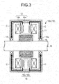
- FIG. 3 is a schematic cross-sectional view of a synchronous machine 10b for explaining an example in which the rotary electric machine 10 is the synchronous machine 10b.
- components substantially the same as those of the induction machine 10a are denoted by the same reference numerals, and the description thereof is not repeated here.
- a rotor 16 of the synchronous machine 10b includes a cylindrical rotor core 16a arranged on the outer peripheral surface of the rotor shaft 14 and a plurality of permanent magnets 16b embedded on the outer peripheral side of the rotor core 16a. That is, the synchronous machine 10b is an interior permanent magnet (IPM) synchronous machine.
- the synchronous machine 10b is not limited to the IPM synchronous machine, and may be a surface permanent magnet (SPM) synchronous machine.
- the AC command unit 52 causes the alternating current to be supplied to the winding 12b of the rotary electric machine 10 (synchronous machine 10b) described above, and the braking unit 54 activates the brake 20 (not illustrated in FIG. 3 ) to cause the rotor shaft 14 to be in a static state or an extremely low speed state. Accordingly, the heat is generated in the stator 12 due to the winding resistance. As illustrated with arrows C in FIG. 3 , the heat generated in the stator 12 is transmitted to the bearing 15 via the frame 11 and the like of which heat transfer coefficient is relatively high, so that the temperature of the bearing 15 is raised.
- the alternating current is supplied to the winding 12b of the rotary electric machine 10.
- the direct current may be supplied thereto by the DC command unit 53. Even when the direct current is supplied to the winding 12b, heat is generated in the stator 12 due to the winding resistance, so that the heat in the stator 12 is transmitted to the bearing 15 through the routes indicated by the arrows B or the arrows C to raise the temperature of the bearing 15.
- the rotating magnetic field is not generated in the stator 12 and rotational torque is not generated in the rotor 13 and the rotor shaft 14, so that the braking unit 54 is not necessarily required to operate the brake 20 to cause the rotor shaft 14 in a static state or the like.
- the brake 20 is connected to the rotor shaft 14 of the rotary electric machine 10 to brake the rotor shaft 14.
- an electromagnetic or hydraulic disk brake can be used.
- the brake 20 is not limited thereto, and may be other type of brake such as a drum brake.
- the temperature sensor 30 is arranged in the vicinity of the rotary electric machine 10, and outputs a signal indicating the temperature of the rotary electric machine 10.
- the heater 40 is mounted to the frame 11 of the rotary electric machine 10, and heats the rotary electric machine 10 when energized by the heater control unit 56. As the heater 40, an electric heater can be used.
- the power conversion unit 60 performs power conversion bidirectionally between the rotary electric machine 10 and the AC power supply 70.
- a matrix converter can be used as the power conversion unit 60.
- FIG. 4 is a diagram illustrating a configuration example of the power conversion unit 60.
- the power conversion unit 60 is a matrix converter including a plurality of bidirectional switches Sru, Ssu, Stu, Srv, Ssv, Stv, Srw, Ssw, and Stw (hereinafter, collectively referred to as a bidirectional switch Sw in some cases) arranged between respective phases of the AC power supply 70 and respective phases of the rotary electric machine 10.
- Each of the bidirectional switches Sru, Ssu, and Stu is connected between each of an R-phase, an S-phase, and a T-phase of the AC power supply 70 and a U-phase of the rotary electric machine 10.
- Each of the bidirectional switches Srv, Ssv, and Stv is connected between each of the R-phase, the S-phase, and the T-phase of the AC power supply 70 and a V-phase of the rotary electric machine 10.
- Each of the bidirectional switches Srw, Ssw, and Stw is connected between each of the R-phase, the S-phase, and the T-phase of the AC power supply 70 and a W-phase of the rotary electric machine 10.
- the bidirectional switch Sw is configured by, as illustrated in FIG. 5 , diodes D1 and D2 and unidirectional switching elements Sw1 and Sw2.
- FIG. 5 is a diagram illustrating a configuration example of the bidirectional switch Sw illustrated in FIG. 4 .
- the unidirectional switching elements Sw1 and Sw2 include a semiconductor switching element such as a metal-oxide-semiconductor field-effect transistor (MOSFET) or an insulated gate bipolar transistor (IGBT).
- MOSFET metal-oxide-semiconductor field-effect transistor
- IGBT insulated gate bipolar transistor
- the configuration of the bidirectional switch Sw is not limited to that illustrated in FIG. 5 .
- the bidirectional switch Sw may have a configuration in which series-connected bodies of the unidirectional switching element and the diode are connected in antiparallel.
- the bidirectional switch Sw may have a configuration in which the unidirectional switching elements configured by reverse-blocking type switching elements are connected in parallel in opposite directions to each other.
- the temperature rise control unit 51 of the control device 50 for a rotary electric machine causes the winding 12b of the rotary electric machine 10 to be energized by controlling the torque.
- the temperature rise control unit 51 outputs a torque command for indicating rotational torque of the rotary electric machine 10 to the AC command unit 52 and the DC command unit 53.
- the temperature rise control unit 51 also outputs an operation command for operating the brake 20 to the braking unit 54.
- the torque command described above is set so that the rotational torque of the rotary electric machine 10 becomes a certain value. Specifically, the torque command is set so that the rotational torque becomes a value lower than braking torque of the brake 20.
- the temperature rise control unit 51 controls the torque such that the rotational torque generated by energization to the winding 12b of the rotary electric machine 10 is lower than the braking torque of the brake 20. Accordingly, the braking unit 54 can easily cause the rotary electric machine 10 to stop or rotate at an extremely low speed by activating the brake 20. Due to this, heat is securely generated in the rotor 13 and the stator 12 of the rotary electric machine 10.
- the temperature rise control unit 51 causes the winding 12b of the rotary electric machine 10 to be energized by controlling the torque, it is possible to prevent that an abnormality determination unit (not illustrated) determines that abnormality occurs in the rotation of the rotary electric machine 10.
- the temperature rise control unit causes the winding of the rotary electric machine to be energized by speed control or position control in a state in which the brake is activated, the speed or the position of the rotor shaft does not reach an indicated value regardless of the energization, so that the abnormality determination unit may determine that abnormality occurs in the rotation of the rotary electric machine in some cases.
- the temperature rise control unit 51 causes the winding 12b of the rotary electric machine 10 to be energized by controlling the torque. Due to this, the commanded rotational torque is generated in the rotary electric machine 10 even when the brake 20 is activated, so that it is possible to prevent that the abnormality determination unit determines that abnormality occurs in the rotation of the rotary electric machine 10.
- the AC command unit 52 controls an operation of the power conversion unit 60 to supply the alternating current corresponding to the torque command to the rotary electric machine 10.
- a burden to the switching element of the bidirectional switch Sw in the power conversion unit 60 can be reduced as compared to a case of DC energization.
- the DC command unit 53 controls the operation of the power conversion unit 60 to supply the direct current corresponding to the torque command.
- the AC command unit 52 and the DC command unit 53 generate a voltage command based on the torque command, and control the operation of the power conversion unit 60 to output a voltage corresponding to the voltage command to the rotary electric machine 10 using a PWM control method of the matrix converter.
- a mode can be switched between an AC mode for supplying the alternating current to the rotary electric machine 10 and a DC mode for supplying the direct current to the rotary electric machine 10.
- the AC command unit 52 controls the operation of the power conversion unit 60 when the AC mode is selected.
- the DC command unit 53 controls the operation of the power conversion unit 60 when the DC mode is selected.
- the selection between the AC mode and the DC mode described above is set in advance.
- the embodiment is not limited thereto.
- a user may perform selection between the AC mode and the DC mode via an external apparatus (not illustrated).
- the braking unit 54 is connected to the brake 20.
- the braking unit 54 controls the operation of the brake 20 to brake the rotor shaft 14 of the rotary electric machine 10.
- the braking unit 54 causes the rotary electric machine 10 to stop or rotate at an extremely low speed by activating the brake 20.
- the rotation at an extremely low speed means rotation at a crawling speed not leading to a steady operation, that is, the rotation at an extremely low speed as compared to the rotation of the rotary electric machine 10 in the steady operation.
- the braking unit 54 activates the brake 20 corresponding to the operation command from the temperature rise control unit 51.
- the braking unit 54 may appropriately activate the brake 20 depending on a rotation state of the rotor shaft 14, for example.
- the determination unit 55 detects the temperature of the rotary electric machine 10 based on a signal output from the temperature sensor 30, and determines whether the detected temperature of the rotary electric machine 10 satisfies a certain condition. When a value of the temperature of the rotary electric machine 10 is relatively low and the bearing 15 is required to be heated, the determination unit 55 determines that the certain condition is satisfied.
- the determination unit 55 is configured to determine that the certain condition is satisfied and the bearing 15 is required to be heated when the temperature of the rotary electric machine 10 is low. If it is determined that the temperature of the rotary electric machine 10 satisfies the certain condition, the determination unit 55 outputs, to the temperature rise control unit 51, a temperature rise permission signal for permitting an operation to raise the temperature of the rotary electric machine 10.
- the heater control unit 56 is connected to the heater 40 and controls the operation of the heater 40.
- the heater control unit 56 is further configured to be capable of detecting presence/absence of a failure in the heater 40 such as a break.
- the heater control unit 56 outputs a failure signal to the temperature rise control unit 51.
- the temperature rise control unit 51 receives the temperature rise permission signal from the determination unit 55 and the failure signal from the heater control unit 56, and causes the winding 12b to be energized to raise the temperature of the rotary electric machine 10.
- the following describes configuration examples of three cases: a case in which the alternating current is supplied to the induction machine 10a; a case in which the alternating current is supplied to the synchronous machine 10b; and the direct current is supplied to the synchronous machine 10b.
- the temperature rise control unit 51 when the configuration is such that the rotary electric machine 10 is the induction machine 10a and the alternating current is supplied to the rotary electric machine 10, first, the temperature rise control unit 51 outputs the operation command to the braking unit 54. When the operation command is output from the temperature rise control unit 51, the braking unit 54 activates the brake 20 to cause the rotary electric machine 10 to be in a static state and the like.
- the temperature rise control unit 51 outputs the torque command to the AC command unit 52.
- the AC command unit 52 receives the torque command, and controls the operation of the power conversion unit 60 so that the alternating current corresponding to the torque command is supplied to the rotary electric machine 10.
- the temperature rise control unit 51 when the configuration is such that the rotary electric machine 10 is the synchronous machine 10b and the alternating current is supplied to the rotary electric machine 10, the temperature rise control unit 51 outputs the operation command to the braking unit 54.
- the braking unit 54 activates the brake 20 to cause the rotary electric machine 10 to be in a static state or an extremely low speed state.
- the temperature rise control unit 51 outputs the torque command to the AC command unit 52.
- the AC command unit 52 controls the operation of the power conversion unit 60 so that the alternating current corresponding to the output torque command is supplied to the rotary electric machine 10.
- FIG. 6 is a graph illustrating the rotational torque generated in the synchronous machine 10b when the alternating current is supplied to the synchronous machine 10b.
- the synchronous machine 10b is vibrated due to torque pulsation of the sinusoidal rotational torque described above.
- a rotating magnetic field speed of the stator 12 should be reduced and the rotor shaft 14 is also required to be rotated at a low speed.
- the temperature rise control unit 51 is required to control the energization so that the sinusoidal rotational torque does not exceed the braking torque of the brake 20. As a result, the temperature of the synchronous machine 10b may not be efficiently raised. Accordingly, when the rotary electric machine 10 is the synchronous machine 10b, the direct current is preferably supplied from the power conversion unit 60 to the rotary electric machine 10.
- the power conversion unit is the inverter
- electric current is concentrated on a specific switching element and the burden is increased, which may cause reduction in reliability of the power conversion unit.
- the matrix converter is used as the power conversion unit 60.
- the temperature rise control unit 51 outputs the torque command to the DC command unit 53.
- the DC command unit 53 receives the torque command, and controls the operation of the power conversion unit 60 including the matrix converter so that the direct current corresponding to the torque command is supplied to the rotary electric machine 10.
- the DC command unit 53 may appropriately switch the bidirectional switches Sru, Ssu, and Stu. Due to this, the electric current is prevented from being concentrated on a specific switching element, so that the burden on the switching element can be reduced and the reduction in the reliability of the power conversion unit 60 can be suppressed.
- the wind power generation system 1 includes a plurality of rotary electric machines 10 according to a use.
- the above-described configuration of raising the temperature of the rotary electric machine 10 can be applied to each of the rotary electric machines 10.
- the rotary electric machine 10 to which the configuration is applied will be described with reference to FIG. 7 and subsequent drawings.
- FIG. 7 is a schematic diagram illustrating the overall wind power generation system 1.
- the temperature sensor 30, the heater 40, and the like are not illustrated.
- the wind power generation system 1 includes a plurality of rotary electric machines 10 and a windmill 83 including a tower body 80, a nacelle 81, and a propeller 82.
- the nacelle 81 is rotatably supported on the tower body 80.
- the propeller 82 includes a hub 82a and a plurality of (for example, three) blades 82b mounted to different positions of the hub 82a. A pitch angle of each of the blades 82b can be changed.
- the rotary electric machines 10 include a rotary electric machine 101 for electric power generation that is connected to the propeller 82 and generates electric power by rotation of the propeller 82, a rotary electric machine 102 for a pitch angle that changes the pitch angle of the blade 82b, and a rotary electric machine 103 for a nacelle that rotates the nacelle 81.
- FIG. 8 is a schematic side view schematically illustrating the configuration of the rotary electric machines 101 and 102, and the like.
- the rotary electric machine 101 is accommodated in the nacelle 81 and connected to the propeller 82 via a propeller shaft 84.
- the rotary electric machine 101 and the propeller 82 are connected to each other so that the rotor shaft 14 and the propeller shaft 84 are coaxial with each other.
- the rotary electric machine 101 is a power generator, which is a rotary electric machine that can also be used as an electric motor.
- a brake 201 and a speed-increasing gear 85 are arranged in the nacelle 81 in addition to the rotary electric machine 101 described above.
- the brake 201 corresponds to the brake 20 illustrated in FIG. 1 , and brakes the rotor shaft 14 of the rotary electric machine 101 and the propeller shaft 84.
- the speed-increasing gear 85 is connected to the propeller shaft 84, increases speed of rotation of the propeller 82, and transmits the rotation to the rotary electric machine 101.
- the rotary electric machine 101 converts rotational energy caused by the rotation, the speed of which is increased by the speed-increasing gear 85, into electric energy to generate electric power.
- the rotary electric machine 102 is accommodated in the hub 82a and connected to the blade 82b via the rotor shaft 14.
- the blade 82b is rotated due to the rotation of the rotary electric machine 102, which changes the pitch angle of the blade 82b.
- FIG. 8 illustrates only one of the blades 82b and the rotary electric machine 102 connected to the blade 82b. However, the rotary electric machines 102 of the number corresponding the blades 82b are actually accommodated in the hub 82a.
- a brake 202 is arranged in the hub 82a in addition to the rotary electric machine 102.
- the brake 202 also corresponds to the brake 20 illustrated in FIG. 1 , and brakes the rotor shaft 14 of the rotary electric machine 102.
- FIG. 9 is a schematic side view schematically illustrating the configuration of the rotary electric machine 103 and the like. As illustrated in FIG. 9 , the rotary electric machine 103 is fixed to a bottom plate 81a of the nacelle 81 and arranged so that the rotor shaft 14 projects to the tower body 80 side. A first gear 90 is attached to a tip of the rotor shaft 14 of the rotary electric machine 103.
- a gear rim 91 is fixed to an upper end position of the tower body 80 in proximity to the nacelle 81.
- a second gear 91a engaged with the first gear 90 is formed on the inner peripheral side of the gear rim 91.
- the nacelle 81 is rotatably supported on the gear rim 91 via the bearing 92. Accordingly, when the rotary electric machine 103 is rotated, the first gear 90 is displaced relatively to the second gear 91a while engaged with the second gear 91a along with the rotation, so that the nacelle 81 is rotated with respect to the tower body 80.
- a brake 203 is arranged on the tower body 80 side of the bottom plate 81a of the nacelle 81.
- the brake 203 corresponds to the brake 20 illustrated in FIG. 1 , specifically, a disk brake.
- a main body part 203a is fixed to the nacelle 81, and a disk part 203b is fixed to the gear rim 91. Accordingly, when the brake 203 is activated to hold the disk part 203b with pad parts 203c of the main body part 203a, the nacelle 81 is prevented from being rotated with respect to the tower body 80.
- the nacelle 81 When the brake 203 is activated, the nacelle 81 is prevented from being rotated with respect to the tower body 80, so that the first gear 90 is not displaced relatively to the second gear 91a and the rotor shaft 14 of the rotary electric machine 103 is braked.
- Configurations of raising the temperatures of the rotary electric machines 101, 102, and 103 are applied to the rotary electric machines 101, 102, and 103, respectively.
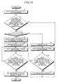
- FIG. 10 is a flowchart illustrating the processing of the temperature raising operation.
- the processing illustrated in FIG. 10 is performed by the control device 50 for a rotary electric machine.
- the processing illustrated in FIG. 10 is performed at the time when the wind power generation system 1 is started.
- the embodiment is not limited thereto.
- the processing may be performed at appropriate timing during a normal operation of the wind power generation system 1.
- the determination unit 55 of the control device 50 for a rotary electric machine detects the temperature of the rotary electric machine 10 based on a signal output from the temperature sensor 30 (Step S1).
- the determination unit 55 determines whether the detected temperature of the rotary electric machine 10 satisfies a certain condition (Step S2).
- the processing at Step S2 is processing for determining whether the temperature of the bearing 15 needs to be raised, and determines whether the temperature of the rotary electric machine 10 is lower than a first certain temperature.
- the processing is ended as it is.
- the heater control unit 56 determines whether the heater 40 is broken down (Step S3).
- Step S3 If it is determined that the heater 40 is broken down (Yes at Step S3), the braking unit 54 activates the brake 20 to cause the rotary electric machine 10 to stop or rotate at an extremely low speed (Step S4).
- the temperature rise control unit 51 causes the power conversion unit 60 to energize the winding 12b of the rotary electric machine 10 (Step S5).
- the AC command unit 52 commands the power conversion unit 60 to supply the alternating current to the rotary electric machine 10.
- the DC command unit 53 commands the power conversion unit 60 to supply the direct current to the rotary electric machine 10. As described above, through the processing at Step S4 or Step S5, the temperature of the rotary electric machine 10 is raised and the temperature of the bearing 15 is raised.
- the determination unit 55 detects the temperature of the rotary electric machine 10 again based on the signal output from the temperature sensor 30 (Step S6). The determination unit 55 then determines whether the temperature detected at Step S6 satisfies the certain condition (Step S7). Specifically, at Step S7, the determination unit 55 determines whether the temperature of the rotary electric machine 10 is lower than a second certain temperature. The second certain temperature is set to be equal to or higher than the first certain temperature.
- Step S7 If it is determined that the temperature of the rotary electric machine 10 satisfies the certain condition, that is, it is determined that the temperature of the rotary electric machine 10 is lower than the second certain temperature (Yes at Step S7), the process returns to Step S6. On the other hand, if it is determined that the temperature of the rotary electric machine 10 does not satisfies the certain condition, that is, when the temperature of the rotary electric machine 10 reaches the second certain temperature (No at Step S7), the bearing 15 is presumed to be heated sufficiently. Accordingly, the temperature rise control unit 51 stops the energization to the winding 12b of the rotary electric machine 10, and the braking unit 54 releases the braking of the brake 20 (Step S8).
- the winding 12b of the rotary electric machine 10 is energized so that the temperature of the rotary electric machine 10 is raised under the certain condition. Due to this, the temperature of the bearing 15 can be raised by energizing the winding 12b at appropriate timing when the bearing 15 is required to be heated.
- the temperature of the bearing 15 is raised by energizing the winding 12b of the rotary electric machine 10 when the heater 40 is broken down, the temperature of the bearing 15 can securely be raised even when the heater 40 is broken down.
- the heater control unit 56 causes the heater 40 to be energized to heat the rotary electric machine 10 (Step S9). Due to this, the temperature of the rotary electric machine 10 is raised, and accordingly, the temperature of the bearing 15 can be raised.
- Step S10 and S11 the processing at Steps S10 and S11 is performed.
- the processing at Steps S10 and S11 is the same as that at Steps S6 and S7 described above, so that the description thereof is not repeated here. If it is determined that the temperature of the rotary electric machine 10 does not satisfy the certain condition (No at Step S11), the heater control unit 56 stops the energization to the heater 40 (Step S12).
- timing to stop the energization to the rotary electric machine 10 is determined based on the temperature of the rotary electric machine 10.
- the configuration may be such that time required for raising the temperature of the rotary electric machine 10 to the second certain temperature is estimated, for example, based on the temperature of the rotary electric machine 10 detected at Step S1, and the winding 12b of the rotary electric machine 10 is energized or the heater 40 is energized until the estimated time elapses.
- the rotary electric machine 10 is energized when the heater 40 is broken down.
- the embodiment is not limited thereto.
- the configuration may be such that both of the rotary electric machine 10 and the heater 40 are energized when the temperature of the rotary electric machine 10 satisfies the certain condition.
- Step S3 may be eliminated, and the processing at Step S4 and Step S9 may be performed when it is determined that the temperature of the rotary electric machine 10 satisfies the certain condition at Step S2. Accordingly, the temperature of the rotary electric machine 10 can be raised at an early stage, and the temperature of the bearing 15 can also be raised at an early stage.
- the configuration may be such that the heater 40 and the heater control unit 56 are removed, and the temperature of the bearing 15 is raised only by energizing the rotary electric machine 10.
- Steps S3 and S9 to S12 are eliminated, and the processing at Step S4 is performed when it is determined that the temperature of the rotary electric machine 10 satisfies the certain condition at Step S2.
- the configuration of the wind power generation system 1 can be simplified by removing the heater 40 and the heater control unit 56, and a need for maintenance of the heater 40 can be eliminated, so that the maintainability of the wind power generation system 1 can be improved.
- the configuration may be such that the brake 20 and the braking unit 54 are removed when the direct current is supplied.
- Step S4 is eliminated, and the processing at Step S5 is performed when it is determined that the heater 40 is broken down at Step S3. In this way, the configuration of the wind power generation system 1 can be simplified by removing the brake 20 and the braking unit 54.
- the wind power generation system 1 includes the rotary electric machine 10 and the temperature rise control unit 51.
- the temperature rise control unit 51 causes the winding 12b of the rotary electric machine 10 to be energized so that the temperature of the rotary electric machine 10 is raised. Accordingly, the temperature of the bearing 15 of the rotary electric machine 10 can be raised without using the heater 40, and the lubrication performance of the bearing 15 can be prevented from being decreased.
- the rotary electric machine 10 is used for wind power generation.
- an application of the rotary electric machine 10 is not limited to the wind power generation.
- the rotary electric machine 10 described above may be applied to a rotary electric machine arranged at a place where an environment temperature is relatively low, such as a hydroelectric power generation system and an outdoor pump.
- the rotary electric machine 10, the brake 20, the control device 50 for a rotary electric machine, and the like described above function as a "rotary electric machine system".
- the wind power generation system 1 includes the brake 20.
- the embodiment is not limited thereto. Any type of braking mechanism may be used as long as it can brake the rotor shaft 14.
- the braking mechanism may be configured to brake the rotor shaft 14 by punching a hole in the rotor shaft 14 and fitting a lock pin into the punched hole.
- the temperature sensor 30 is arranged corresponding to each of the rotary electric machines 10.
- the embodiment is not limited thereto.
- single temperature sensor may be arranged in the nacelle 81 or outdoors, and the determination unit 55 may determine whether the temperature in the nacelle 81 or an outdoor environment temperature detected by the single temperature sensor satisfies the certain condition.
- the matrix converter is exemplified as the power conversion unit 60.
- the power conversion unit 60 may be an inverter.
- FIG. 1 illustrates an example in which the control device 50 for a rotary electric machine and the power conversion unit 60 are separately provided.
- the control device 50 for a rotary electric machine and the power conversion unit 60 may be integrally configured.
Landscapes
- Engineering & Computer Science (AREA)
- General Engineering & Computer Science (AREA)
- Power Engineering (AREA)
- Mechanical Engineering (AREA)
- Sustainable Energy (AREA)
- Sustainable Development (AREA)
- Life Sciences & Earth Sciences (AREA)
- Chemical & Material Sciences (AREA)
- Combustion & Propulsion (AREA)
- Physics & Mathematics (AREA)
- Thermal Sciences (AREA)
- Control Of Eletrric Generators (AREA)
- Wind Motors (AREA)
Applications Claiming Priority (1)
| Application Number | Priority Date | Filing Date | Title |
|---|---|---|---|
| JP2013200833A JP2015068186A (ja) | 2013-09-27 | 2013-09-27 | 風力発電システム、風力発電システムの制御方法、回転電機システムおよび回転電機の制御装置 |
Publications (2)
| Publication Number | Publication Date |
|---|---|
| EP2854284A2 true EP2854284A2 (de) | 2015-04-01 |
| EP2854284A3 EP2854284A3 (de) | 2015-11-04 |
Family
ID=51610014
Family Applications (1)
| Application Number | Title | Priority Date | Filing Date |
|---|---|---|---|
| EP14186294.6A Withdrawn EP2854284A3 (de) | 2013-09-27 | 2014-09-25 | Windenergieerzeugungssystem, Verfahren zur Steuerung des Windenergieerzeugungssystems, elektrisches Drehmaschinensystem und Steuerungsvorrichtung für elektrische Drehmaschine |
Country Status (5)
| Country | Link |
|---|---|
| US (1) | US20150091302A1 (de) |
| EP (1) | EP2854284A3 (de) |
| JP (1) | JP2015068186A (de) |
| KR (1) | KR20150035431A (de) |
| CN (1) | CN104518618A (de) |
Cited By (2)
| Publication number | Priority date | Publication date | Assignee | Title |
|---|---|---|---|---|
| EP3613136A4 (de) * | 2017-04-18 | 2020-11-11 | Pascal Chretien | Elektrischer antriebsstrang und verfahren zum speisen eines elektrischen antriebsstrangs |
| EP3637614B1 (de) * | 2015-10-20 | 2022-12-07 | Regal Beloit America, Inc. | System und verfahren zur steuerung eines elektrischen motors |
Families Citing this family (6)
| Publication number | Priority date | Publication date | Assignee | Title |
|---|---|---|---|---|
| CN106527320B (zh) * | 2016-12-12 | 2018-11-02 | 北京金风科创风电设备有限公司 | 发电机组中加热器的检测维护系统和方法 |
| CN106704100B (zh) * | 2016-12-30 | 2019-07-02 | 北京金风科创风电设备有限公司 | 风力发电机组、风力发电机组功率控制方法及装置 |
| CN108301990B (zh) * | 2018-03-01 | 2019-08-30 | 北京金风慧能技术有限公司 | 风力发电机组及其高速轴刹车盘的温度监测系统和方法 |
| JP7026031B2 (ja) * | 2018-10-17 | 2022-02-25 | 東芝三菱電機産業システム株式会社 | 回転電機システム、スペースヒータシステム、およびスペースヒータの制御方法 |
| US12535046B2 (en) | 2020-07-17 | 2026-01-27 | Innovator Energy Llc | Fluid displacement energy storage systems and processes to enable pressure equilibrized subsea tank |
| CN114576102B (zh) * | 2020-12-02 | 2024-09-20 | 金风科技股份有限公司 | 风电机组轴承状态的预测方法、装置、设备及存储介质 |
Citations (1)
| Publication number | Priority date | Publication date | Assignee | Title |
|---|---|---|---|---|
| JP2007198167A (ja) | 2006-01-24 | 2007-08-09 | Fuji Heavy Ind Ltd | 水平軸風車 |
Family Cites Families (7)
| Publication number | Priority date | Publication date | Assignee | Title |
|---|---|---|---|---|
| JPS61177199A (ja) * | 1985-01-31 | 1986-08-08 | Toshiba Corp | タ−ビン発電機システム |
| NL1013129C2 (nl) * | 1999-09-24 | 2001-03-27 | Lagerwey Windturbine B V | Windmolen. |
| DE10119625B4 (de) * | 2001-04-20 | 2004-04-08 | Wobben, Aloys, Dipl.-Ing. | Verfahren zur Steuerung einer Windenergieanlage |
| US7425771B2 (en) * | 2006-03-17 | 2008-09-16 | Ingeteam S.A. | Variable speed wind turbine having an exciter machine and a power converter not connected to the grid |
| US20070246302A1 (en) * | 2006-04-21 | 2007-10-25 | Pratt & Whitney Canada Corp. | Pre-heating an aircraft oil reservoir |
| JP5022451B2 (ja) * | 2009-06-05 | 2012-09-12 | 三菱重工業株式会社 | 風力発電装置及びその制御方法並びに風力発電システム |
| JP5013283B2 (ja) * | 2010-02-17 | 2012-08-29 | 株式会社安川電機 | マトリクスコンバータの制御装置 |
-
2013
- 2013-09-27 JP JP2013200833A patent/JP2015068186A/ja active Pending
-
2014
- 2014-09-09 CN CN201410456957.7A patent/CN104518618A/zh active Pending
- 2014-09-12 US US14/484,273 patent/US20150091302A1/en not_active Abandoned
- 2014-09-25 EP EP14186294.6A patent/EP2854284A3/de not_active Withdrawn
- 2014-09-25 KR KR20140128450A patent/KR20150035431A/ko not_active Ceased
Patent Citations (1)
| Publication number | Priority date | Publication date | Assignee | Title |
|---|---|---|---|---|
| JP2007198167A (ja) | 2006-01-24 | 2007-08-09 | Fuji Heavy Ind Ltd | 水平軸風車 |
Cited By (3)
| Publication number | Priority date | Publication date | Assignee | Title |
|---|---|---|---|---|
| EP3637614B1 (de) * | 2015-10-20 | 2022-12-07 | Regal Beloit America, Inc. | System und verfahren zur steuerung eines elektrischen motors |
| EP3613136A4 (de) * | 2017-04-18 | 2020-11-11 | Pascal Chretien | Elektrischer antriebsstrang und verfahren zum speisen eines elektrischen antriebsstrangs |
| US11114960B2 (en) | 2017-04-18 | 2021-09-07 | Pascal Chretien | Electric drive train and method for feeding an electric drive train |
Also Published As
| Publication number | Publication date |
|---|---|
| US20150091302A1 (en) | 2015-04-02 |
| KR20150035431A (ko) | 2015-04-06 |
| CN104518618A (zh) | 2015-04-15 |
| JP2015068186A (ja) | 2015-04-13 |
| EP2854284A3 (de) | 2015-11-04 |
Similar Documents
| Publication | Publication Date | Title |
|---|---|---|
| EP2854284A2 (de) | Windenergieerzeugungssystem, Verfahren zur Steuerung des Windenergieerzeugungssystems, elektrisches Drehmaschinensystem und Steuerungsvorrichtung für elektrische Drehmaschine | |
| US9863400B2 (en) | System and method for controlling a wind turbine system | |
| EP3004637B2 (de) | Verfahren zum betreiben eines windturbinensystems mit dynamischer bremse | |
| JP5372705B2 (ja) | 電力変換装置 | |
| CN101737247B (zh) | 用于风力涡轮机的保护系统 | |
| ES2440925T3 (es) | Instalación de energía eólica | |
| US20120133343A1 (en) | Wind turbine having a high-voltage ride through (hvrt) mode | |
| EP3276165A1 (de) | Batterieunterstütztes bremssystem für eine windturbine | |
| BR112012023785B1 (pt) | Dispositivo de acionamento de passo | |
| JP2007202311A5 (de) | ||
| BR112018001401B1 (pt) | Sistema de recuperação de energia de frenagem para um motor elétrico, ventilador médico e método para recuperação de energia para um motor elétrico | |
| JP2015010579A (ja) | 風力発電システム | |
| KR20080066575A (ko) | 발전 장치 | |
| EP3304726B1 (de) | Kraft-wärme-kopplungsanlage mit startersystem | |
| WO2017006658A1 (ja) | 風車の回転速度制御方法及び風力発電装置 | |
| EP3457556A1 (de) | Verfahren zum betrieb von elektrischen energiesystemen | |
| JP2016153624A (ja) | 電動圧縮機 | |
| CN102611365A (zh) | 风力涡轮机 | |
| CN115552791A (zh) | 基于温度读数控制电驱动系统 | |
| EP2532889B1 (de) | Windturbine und Verfahren zum Betrieb einer Windturbine | |
| WO2015001403A1 (en) | Blade pitching system for a horizontal axis wind turbine | |
| JP3772979B2 (ja) | 回転機械の制動制御装置 | |
| JP2009239987A (ja) | 膨張タービン制動装置 | |
| EP2704310B1 (de) | Verfahren zum Betrieb einer solchen elektrischen Maschine | |
| KR20170095484A (ko) | 전력 계통 연계형 수직축 풍력발전기의 제동장치 및 제동방법 |
Legal Events
| Date | Code | Title | Description |
|---|---|---|---|
| PUAI | Public reference made under article 153(3) epc to a published international application that has entered the european phase |
Free format text: ORIGINAL CODE: 0009012 |
|
| 17P | Request for examination filed |
Effective date: 20140925 |
|
| AK | Designated contracting states |
Kind code of ref document: A2 Designated state(s): AL AT BE BG CH CY CZ DE DK EE ES FI FR GB GR HR HU IE IS IT LI LT LU LV MC MK MT NL NO PL PT RO RS SE SI SK SM TR |
|
| AX | Request for extension of the european patent |
Extension state: BA ME |
|
| PUAL | Search report despatched |
Free format text: ORIGINAL CODE: 0009013 |
|
| AK | Designated contracting states |
Kind code of ref document: A3 Designated state(s): AL AT BE BG CH CY CZ DE DK EE ES FI FR GB GR HR HU IE IS IT LI LT LU LV MC MK MT NL NO PL PT RO RS SE SI SK SM TR |
|
| AX | Request for extension of the european patent |
Extension state: BA ME |
|
| RIC1 | Information provided on ipc code assigned before grant |
Ipc: H02P 27/16 20060101AFI20150930BHEP Ipc: H02P 3/18 20060101ALI20150930BHEP Ipc: H02P 29/00 20060101ALI20150930BHEP |
|
| STAA | Information on the status of an ep patent application or granted ep patent |
Free format text: STATUS: THE APPLICATION IS DEEMED TO BE WITHDRAWN |
|
| 18D | Application deemed to be withdrawn |
Effective date: 20160505 |