EP2854145A1 - Contactless electrical-power-supplying transformer for moving body - Google Patents
Contactless electrical-power-supplying transformer for moving body Download PDFInfo
- Publication number
- EP2854145A1 EP2854145A1 EP13793139.0A EP13793139A EP2854145A1 EP 2854145 A1 EP2854145 A1 EP 2854145A1 EP 13793139 A EP13793139 A EP 13793139A EP 2854145 A1 EP2854145 A1 EP 2854145A1
- Authority
- EP
- European Patent Office
- Prior art keywords
- coil
- sides wound
- sides
- coupled
- wound coils
- Prior art date
- Legal status (The legal status is an assumption and is not a legal conclusion. Google has not performed a legal analysis and makes no representation as to the accuracy of the status listed.)
- Granted
Links
Images


Classifications
-
- H—ELECTRICITY
- H01—ELECTRIC ELEMENTS
- H01F—MAGNETS; INDUCTANCES; TRANSFORMERS; SELECTION OF MATERIALS FOR THEIR MAGNETIC PROPERTIES
- H01F27/00—Details of transformers or inductances, in general
- H01F27/28—Coils; Windings; Conductive connections
- H01F27/30—Fastening or clamping coils, windings, or parts thereof together; Fastening or mounting coils or windings on core, casing, or other support
- H01F27/306—Fastening or mounting coils or windings on core, casing or other support
-
- H—ELECTRICITY
- H01—ELECTRIC ELEMENTS
- H01F—MAGNETS; INDUCTANCES; TRANSFORMERS; SELECTION OF MATERIALS FOR THEIR MAGNETIC PROPERTIES
- H01F38/00—Adaptations of transformers or inductances for specific applications or functions
- H01F38/14—Inductive couplings
-
- B—PERFORMING OPERATIONS; TRANSPORTING
- B60—VEHICLES IN GENERAL
- B60L—PROPULSION OF ELECTRICALLY-PROPELLED VEHICLES; SUPPLYING ELECTRIC POWER FOR AUXILIARY EQUIPMENT OF ELECTRICALLY-PROPELLED VEHICLES; ELECTRODYNAMIC BRAKE SYSTEMS FOR VEHICLES IN GENERAL; MAGNETIC SUSPENSION OR LEVITATION FOR VEHICLES; MONITORING OPERATING VARIABLES OF ELECTRICALLY-PROPELLED VEHICLES; ELECTRIC SAFETY DEVICES FOR ELECTRICALLY-PROPELLED VEHICLES
- B60L1/00—Supplying electric power to auxiliary equipment of vehicles
- B60L1/02—Supplying electric power to auxiliary equipment of vehicles to electric heating circuits
-
- B—PERFORMING OPERATIONS; TRANSPORTING
- B60—VEHICLES IN GENERAL
- B60L—PROPULSION OF ELECTRICALLY-PROPELLED VEHICLES; SUPPLYING ELECTRIC POWER FOR AUXILIARY EQUIPMENT OF ELECTRICALLY-PROPELLED VEHICLES; ELECTRODYNAMIC BRAKE SYSTEMS FOR VEHICLES IN GENERAL; MAGNETIC SUSPENSION OR LEVITATION FOR VEHICLES; MONITORING OPERATING VARIABLES OF ELECTRICALLY-PROPELLED VEHICLES; ELECTRIC SAFETY DEVICES FOR ELECTRICALLY-PROPELLED VEHICLES
- B60L53/00—Methods of charging batteries, specially adapted for electric vehicles; Charging stations or on-board charging equipment therefor; Exchange of energy storage elements in electric vehicles
- B60L53/10—Methods of charging batteries, specially adapted for electric vehicles; Charging stations or on-board charging equipment therefor; Exchange of energy storage elements in electric vehicles characterised by the energy transfer between the charging station and the vehicle
- B60L53/12—Inductive energy transfer
- B60L53/122—Circuits or methods for driving the primary coil, e.g. supplying electric power to the coil
-
- B—PERFORMING OPERATIONS; TRANSPORTING
- B60—VEHICLES IN GENERAL
- B60L—PROPULSION OF ELECTRICALLY-PROPELLED VEHICLES; SUPPLYING ELECTRIC POWER FOR AUXILIARY EQUIPMENT OF ELECTRICALLY-PROPELLED VEHICLES; ELECTRODYNAMIC BRAKE SYSTEMS FOR VEHICLES IN GENERAL; MAGNETIC SUSPENSION OR LEVITATION FOR VEHICLES; MONITORING OPERATING VARIABLES OF ELECTRICALLY-PROPELLED VEHICLES; ELECTRIC SAFETY DEVICES FOR ELECTRICALLY-PROPELLED VEHICLES
- B60L53/00—Methods of charging batteries, specially adapted for electric vehicles; Charging stations or on-board charging equipment therefor; Exchange of energy storage elements in electric vehicles
- B60L53/30—Constructional details of charging stations
- B60L53/35—Means for automatic or assisted adjustment of the relative position of charging devices and vehicles
- B60L53/36—Means for automatic or assisted adjustment of the relative position of charging devices and vehicles by positioning the vehicle
-
- H—ELECTRICITY
- H01—ELECTRIC ELEMENTS
- H01F—MAGNETS; INDUCTANCES; TRANSFORMERS; SELECTION OF MATERIALS FOR THEIR MAGNETIC PROPERTIES
- H01F27/00—Details of transformers or inductances, in general
- H01F27/24—Magnetic cores
- H01F27/255—Magnetic cores made from particles
-
- H—ELECTRICITY
- H02—GENERATION; CONVERSION OR DISTRIBUTION OF ELECTRIC POWER
- H02J—CIRCUIT ARRANGEMENTS OR SYSTEMS FOR SUPPLYING OR DISTRIBUTING ELECTRIC POWER; SYSTEMS FOR STORING ELECTRIC ENERGY
- H02J50/00—Circuit arrangements or systems for wireless supply or distribution of electric power
- H02J50/10—Circuit arrangements or systems for wireless supply or distribution of electric power using inductive coupling
-
- B—PERFORMING OPERATIONS; TRANSPORTING
- B60—VEHICLES IN GENERAL
- B60L—PROPULSION OF ELECTRICALLY-PROPELLED VEHICLES; SUPPLYING ELECTRIC POWER FOR AUXILIARY EQUIPMENT OF ELECTRICALLY-PROPELLED VEHICLES; ELECTRODYNAMIC BRAKE SYSTEMS FOR VEHICLES IN GENERAL; MAGNETIC SUSPENSION OR LEVITATION FOR VEHICLES; MONITORING OPERATING VARIABLES OF ELECTRICALLY-PROPELLED VEHICLES; ELECTRIC SAFETY DEVICES FOR ELECTRICALLY-PROPELLED VEHICLES
- B60L2240/00—Control parameters of input or output; Target parameters
- B60L2240/10—Vehicle control parameters
- B60L2240/36—Temperature of vehicle components or parts
-
- B—PERFORMING OPERATIONS; TRANSPORTING
- B60—VEHICLES IN GENERAL
- B60L—PROPULSION OF ELECTRICALLY-PROPELLED VEHICLES; SUPPLYING ELECTRIC POWER FOR AUXILIARY EQUIPMENT OF ELECTRICALLY-PROPELLED VEHICLES; ELECTRODYNAMIC BRAKE SYSTEMS FOR VEHICLES IN GENERAL; MAGNETIC SUSPENSION OR LEVITATION FOR VEHICLES; MONITORING OPERATING VARIABLES OF ELECTRICALLY-PROPELLED VEHICLES; ELECTRIC SAFETY DEVICES FOR ELECTRICALLY-PROPELLED VEHICLES
- B60L2270/00—Problem solutions or means not otherwise provided for
- B60L2270/10—Emission reduction
- B60L2270/14—Emission reduction of noise
- B60L2270/147—Emission reduction of noise electro magnetic [EMI]
-
- H—ELECTRICITY
- H02—GENERATION; CONVERSION OR DISTRIBUTION OF ELECTRIC POWER
- H02J—CIRCUIT ARRANGEMENTS OR SYSTEMS FOR SUPPLYING OR DISTRIBUTING ELECTRIC POWER; SYSTEMS FOR STORING ELECTRIC ENERGY
- H02J50/00—Circuit arrangements or systems for wireless supply or distribution of electric power
- H02J50/70—Circuit arrangements or systems for wireless supply or distribution of electric power involving the reduction of electric, magnetic or electromagnetic leakage fields
-
- Y—GENERAL TAGGING OF NEW TECHNOLOGICAL DEVELOPMENTS; GENERAL TAGGING OF CROSS-SECTIONAL TECHNOLOGIES SPANNING OVER SEVERAL SECTIONS OF THE IPC; TECHNICAL SUBJECTS COVERED BY FORMER USPC CROSS-REFERENCE ART COLLECTIONS [XRACs] AND DIGESTS
- Y02—TECHNOLOGIES OR APPLICATIONS FOR MITIGATION OR ADAPTATION AGAINST CLIMATE CHANGE
- Y02T—CLIMATE CHANGE MITIGATION TECHNOLOGIES RELATED TO TRANSPORTATION
- Y02T10/00—Road transport of goods or passengers
- Y02T10/60—Other road transportation technologies with climate change mitigation effect
- Y02T10/70—Energy storage systems for electromobility, e.g. batteries
-
- Y—GENERAL TAGGING OF NEW TECHNOLOGICAL DEVELOPMENTS; GENERAL TAGGING OF CROSS-SECTIONAL TECHNOLOGIES SPANNING OVER SEVERAL SECTIONS OF THE IPC; TECHNICAL SUBJECTS COVERED BY FORMER USPC CROSS-REFERENCE ART COLLECTIONS [XRACs] AND DIGESTS
- Y02—TECHNOLOGIES OR APPLICATIONS FOR MITIGATION OR ADAPTATION AGAINST CLIMATE CHANGE
- Y02T—CLIMATE CHANGE MITIGATION TECHNOLOGIES RELATED TO TRANSPORTATION
- Y02T10/00—Road transport of goods or passengers
- Y02T10/60—Other road transportation technologies with climate change mitigation effect
- Y02T10/7072—Electromobility specific charging systems or methods for batteries, ultracapacitors, supercapacitors or double-layer capacitors
-
- Y—GENERAL TAGGING OF NEW TECHNOLOGICAL DEVELOPMENTS; GENERAL TAGGING OF CROSS-SECTIONAL TECHNOLOGIES SPANNING OVER SEVERAL SECTIONS OF THE IPC; TECHNICAL SUBJECTS COVERED BY FORMER USPC CROSS-REFERENCE ART COLLECTIONS [XRACs] AND DIGESTS
- Y02—TECHNOLOGIES OR APPLICATIONS FOR MITIGATION OR ADAPTATION AGAINST CLIMATE CHANGE
- Y02T—CLIMATE CHANGE MITIGATION TECHNOLOGIES RELATED TO TRANSPORTATION
- Y02T90/00—Enabling technologies or technologies with a potential or indirect contribution to GHG emissions mitigation
- Y02T90/10—Technologies relating to charging of electric vehicles
- Y02T90/12—Electric charging stations
-
- Y—GENERAL TAGGING OF NEW TECHNOLOGICAL DEVELOPMENTS; GENERAL TAGGING OF CROSS-SECTIONAL TECHNOLOGIES SPANNING OVER SEVERAL SECTIONS OF THE IPC; TECHNICAL SUBJECTS COVERED BY FORMER USPC CROSS-REFERENCE ART COLLECTIONS [XRACs] AND DIGESTS
- Y02—TECHNOLOGIES OR APPLICATIONS FOR MITIGATION OR ADAPTATION AGAINST CLIMATE CHANGE
- Y02T—CLIMATE CHANGE MITIGATION TECHNOLOGIES RELATED TO TRANSPORTATION
- Y02T90/00—Enabling technologies or technologies with a potential or indirect contribution to GHG emissions mitigation
- Y02T90/10—Technologies relating to charging of electric vehicles
- Y02T90/14—Plug-in electric vehicles
Definitions
- the present invention relates to a contactless power transfer transformer for a moving body, which transfers power to a moving body such as an electrical vehicle in a contactless manner.
- the present invention relates to a transformer that can easily increase its capacity while avoiding influence on health due to magnetic field exposure, as well as that is compatible with different types of contactless power transfer transformer.
- FIG. 18 As a system for charging a battery of an electric vehicle or a plug-in hybrid car, there has been developing a method that transfers power to the vehicle in contactless manner by using electromagnetic induction, as illustrated in FIG. 18 .
- Such a method transfers power from a primary transformer (power transmission coil) 10 installed on the ground to a secondary transformer (power reception coil) 20 of the contactless power transfer transformer, installed on a floor of the vehicle.
- Patent Literature 1 as the power transmission coil and the power reception coil of the contactless power transfer transformer used in this system, there is disclosed a configuration in which an electric wiring is wound in a flattened circle and provided on one face of a flat plate ferrite magnetic core 21, 31, as illustrated in FIGS. 19A and 19B .
- Such a coil is referred to as "one-side wound coil” since the winding wires 22, 23 are wound only at one side of the ferrite magnetic cores 21, 31.
- FIG. 19A is a cross sectional view of the power transmission coil and the power reception coil
- FIG. 19B is a plan view of the power transmission coil and the power reception coil.
- the power transfer efficiency of the contactless power transfer transformer that uses the one-side wound coil largely decreases when a vehicle is stopped at a position different from a vehicle stop position and the power transmission coil and the power reception coil do not oppose each other, or when a gap between the power transmission coil and the power reception coil changes. In order to increase the permissible amount with respect to the positional variation or the gap variation, it becomes necessary to increase the sizes of the power transmission coil and the power reception coil.
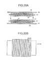
- FIGS. 20A and 20B in such a contactless power transfer transformer, the power transmission coil and the power reception coil are configured by winding the winding wires 62, 64 around the ferrite cores 61, 63.
- Such a coil is referred to as "both-sides wound coil”.
- the "square core" is used as the ferrite cores 61, 63.
- FIG. 20A is a cross sectional view of the power transmission coil and the power reception coil
- FIG. 20B is a plan view of the power transmission coil and the power reception coil.
- a main magnetic flux 67 that circles around the magnetic pole portions of the ferrite cores 61, 63 is generated. Additionally, bypassing leakage magnetic fluxes 68, 69 are generated on the non-opposing sides of the power transmission coil and the power reception coil. If the leakage magnetic fluxes 68, 69 enter an iron plate or the like of the floor of the vehicle, induced current flows through the iron plate and the iron plate is heated, thereby the power transfer efficiency decreases. In order to avoid the decrease in the power transfer efficiency, it is required to magnetically shield the leakage magnetic fluxes 68, 69 by arranging non-magnetic good conductors 65, 66 such as an aluminum plate at back faces of the power transmission coil and the power reception coil.
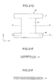
- a power transmission coil and a power reception coil as illustrated in FIGS. 21A to 21F .
- a ferrite core is configured in H-shape
- parts 41 and 42 arranged at both ends of the H-shape and being parallel to each other are provided as magnetic pole portions
- a winding wire 50 is wound around a part 43 (the part connects between the magnetic pole portions, and is also referred to as a wound portion) corresponding to a horizontal pole of the H-shape.
- FIG. 21A is a state in which the winding wire 50 is wound around the ferrite core 40
- FIG. 21D is a state in which the winding wire 50 is not wound around the ferrite core 40
- FIG. 21B is a cross sectional view taken along a line A-A of FIG. 21A
- FIG. 21C is a cross sectional view taken along a line B-B of FIG. 21A
- FIG. 21E is a cross sectional view taken along a line A-A of FIG. 21D
- FIG. 21F is a cross sectional view taken along a line B-B of FIG. 21D .
- the power transmission coil and the power reception coil each configured by a both-sides wound coil by using this H-shape core are arranged to oppose each other with a spacing therebetween at a normal gap length of 70 mm and the power transfer of 3 kW is performed.
- the following power transfer properties are obtained.
- the efficiency of the transformer is 95 %
- the permissible amount of positional variation in the left and right direction (y-direction in FIG. 21A ) is ⁇ 150 mm
- the permissible amount of positional variation in the front and back direction (x-direction in FIG. 21A ) is ⁇ 60 mm
- the efficiency at which the normal gap length is increased to 100 mm is 92 %.
- the permissible amount of the positional variation, the gap variation between the power transmission coil and the power reception coil, and/or the like is large. This means that, from a slightly different angle, the magnetic field (leakage magnetic field) diffusing to the surrounding is larger than the one-side wound coil.
- the present invention is made in view of the foregoing, and an object of the present invention is to provide a contactless power transfer transformer for a moving body, which is capable of increasing capacity of the transformer while suppressing the leakage magnetic field.
- a contactless power transfer transformer for a moving body includes a power transmission coil and a power reception coil.
- the power reception coil is installed at a position at which the moving body is installed (e.g., as illustrated in FIG. 18 ).
- Contactless power transfer is performed when the moving body is moved to a power transfer position at which the power transmission coil and the power reception coil oppose each other.
- At least one of the power transmission coil and the power reception coil is configured a coupled and both-sides wound coil.
- the coupled and both-sides wound coil is configured by combining a plurality of single both-sides wound coils.
- a winding wire is wound around a wound portion between magnetic pole portions of a core in each of the single both-sides wound coils.
- the single both-sides wound coils are combined so that each wound portion of the single both-sides wound coils is arranged linearly with respect to each other, one of the magnetic pole portions of one of the single both-sides wound coils is connected to one of the magnetic pole portions of adjacent one of the single both-sides wound coils, and directions of magnetic fluxes in a vertical direction toward a corresponding coil from each of the magnetic pole portions connected to each other are identical.
- Each of the single both-sides wound coils is selected so that a leakage magnetic flux around the moving body of when the coupled and both-sides wound coil configured by two single both-sides wound coils is arranged at the install position of the moving body does not exceed a predetermined value.
- a number of the single both-sides wound coils configuring the coupled and both-sides wound coil is set so that a value obtained by multiplying power transfer capacity of one of the selected single both-sides wound coils by the number satisfies power transfer capacity of the contactless power transfer transformer.
- the leakage magnetic fields generated by each of the single both-sides wound coils cancel each other at a location far away.
- the principle therebehind is considered similar to the principle in which the attenuation characteristic of the leakage magnetic field is good for the one-side wound coil of FIG. 19 . Therefore, when the single both-sides wound coil that configures the coupled and both-sides wound coil is selected, a coupled and both-sides wound coil configured by two single both-sides wound coils are placed at an install position, and single both-sides wound coils that satisfy a condition of leakage magnetic field is selected.
- a number of the single both-sides wound coils to be used for the coupled and both-sides wound coil is desired to be an even number in order to reduce the leakage magnetic flux.
- the coupled and both-sides wound coil may be configured by an odd number of the single both-sides wound coils.
- the power reception coil configured by the coupled and both-sides wound coil can be installed at an install position at a bottom face of the moving body so that an arrangement direction of the single both-sides wound coils in the coupled and both-sides wound coil coincides with a front and back direction of the moving body.
- the permissible amount of the positional variation in a direction parallel to a pair of the magnetic pole portions is smaller than the permissible amount of the positional variation in a direction (i.e., an array direction of the both-sides wound coils) perpendicular to the pair of the magnetic pole portions. Therefore, a front and back direction of the moving body, which is a direction easier to provide solutions (for example, a tire block) for preventing the positional variation, can be made to coincide with a direction toward which the permissible level of the positional variation is low.
- each of the single both-sides wound coils may include an H-shape core in which the wound portion is arranged at a middle part between a pair of the parallel magnetic pole portions.
- the H-shape core By using the H-shape core, an amount of ferrite is reduced, and it becomes capable of reducing the weight, the size, and the cost. Further, the length of the magnetic pole portion (the length of the H-shape in the longitudinal direction) can be increased to increase the permissible amount of the positional variation or the gap variation.
- a width in the arrangement direction of the single both-sides wound coils of the coupled and both-sides wound coil and obtained by adding widths of the connected magnetic pole portions is D1
- a width of the magnetic pole portion positioned at an end portion of the coupled and both-sides wound coil is D2
- D1 ⁇ 2 ⁇ D2 to shorten the length of the coupled and both-sides wound coil in the arrangement direction.
- a width of a single magnetic pole portion may be thin.
- the power transmission coil and the power reception coil may each be configured by the coupled and both-sides wound coil that is configured by combining the two single both-sides wound coils, in the coupled and both-sides wound coil of one of the power transmission coil and the power reception coil, winding wires of the two single both-sides wound coils may be electrically connected to each other in series, and in the coupled and both-sides wound coil of other one of the power transmission coil and the power reception coil, the winding wires of the two both-sides wound coils may be electrically connected to each other in parallel.
- the power transmission coil and the power reception coil may each be configured by the coupled and both-sides wound coil that is configured by combining m pairs of the two single both-sides wound coils, in the coupled and both-sides wound coil of one of the power transmission coil and the power reception coil, the winding wires of each of the two single both-sides wound coils in each of the m pairs of the two single both-sides wound coils may be electrically connected to each other in series, and winding wires of each of the m pairs of the two single both-sides wound coils may be electrically connected to each other in parallel, and in the coupled and both-sides wound coil of other one of the power transmission coil and the power reception coil, the winding wires of each of the two single both-sides wound coils in each of the m pairs of the two single both-sides wound coils may be electrically connected to each other in parallel, and the winding wires of each of the m pairs of the two single both-sides wound coils may be electrically connected to each other in parallel
- the power transmission coil and the power reception coil may both be configured by the coupled and both-sides wound coil configured by combining m pairs of the two single both-sides wound coils, and in the coupled and both-sides wound coil, the winding wires of each of the two single both-sides wound coils in each of the m pairs of the two single both-sides wound coils may be electrically connected to each other in series, and the winding wires of each of the m pairs of the single both-sides wound coils are electrically connected to each other in parallel.
- the coupled and both-sides wound coil that is configured by combining the two single both-sides wound coils can perform the power transfer not only with respect to the same type of coupled and both-sides wound coil but also with respect to one-side wound coil.
- a contactless power transfer transformer for a moving body of the present invention capacity can easily be increased while suppressing the leakage magnetic field. Further, it is possible to perform power transfer not only with respect to the same type of both-sides wound coil but also with respect to different type of one-side wound coil. Therefore, the contactless power transfer transformer for a moving body of the present invention is compatible with the one-side wound coil.
- FIG. 1A and FIG. 1B schematically illustrates a power transmission coil of a moving body contactless power transfer transformer according to an embodiment of the present embodiment.
- a power reception coil has the same configuration.
- the single both-sides wound coils 100, 200 are configured such that a litz wire is wound around a wound portion of an H-shape core.
- the H-shape core is configured by: a pair of magnetic pole cores 80 that are parallel to each other; and a winding wire core 81 that is orthogonal to the magnetic pole cores 80. Both the magnetic pole cores 80 and the winding wire core 81 are ferrite cores.
- a winding wire portion 50 around which an electric wire is wound is attached at the middle of the winding wire core 81. Both ends of a ferrite plate protruding from both sides of the winding wire portion 50 are connected to the magnetic pole cores 80 via bottom-layer ferrite plates 82.
- the bottom-layer ferrite plates 82 are laminated at a side opposing a corresponding coil so as to raise a height of the upper most portion of the magnetic pole cores 80 to the height of the winding wire portion 50 or greater.
- the magnetic pole cores 80 are arranged above the bottom-layer ferrite plate.
- a magnetic gap length G2 can be set to a length the same as a length of spacing G1 of the winding wire portion 50 or shorter. As described above, by making the magnetic gap length short, a coupling coefficient between the coils becomes high and the power transfer efficiency and the maximum power transfer power increase.
- the magnetic pole core 180 of the single both-sides wound coil 100 is arranged and connected to a magnetic pole core 280 of an adjacent single both-sides wound coil 200. Further, a winding wire core 181 of the single both-sides wound coil 100 is combined with a winding wire core 281 of the adjacent single both-sides wound coil 200 so as to be next to each other in linear manner.
- the directions of the main magnetic fluxes in the vertical direction toward the corresponding coil from the magnetic pole cores 180, 280 arranged and connected with each other are set to be the same. Consequently, the magnetic field between the power transmission coil 10 and the power reception coil 20 becomes stronger, and the power transfer power increases.
- the power transfer power of the coupled and both-sides wound coil in which a plurality of single both-sides wound coils are combined increases as a number of the both-sides wound coils increases, in proportional manner.
- FIG. 3A illustrates a case in which winding wires of the two single both-sides wound coils 100, 200 are connected to each other in parallel while winding wire directions of the two single both-sides wound coils 100, 200 are made opposite each other, in order to increase the power transfer power of the coupled and both-sides wound coil to be double the power transfer power of the single both-sides wound coil.
- the power reception coil configured by the coupled and both-sides wound coil is installed at an install position on an underfloor surface of the vehicle such that an arrangement direction of the single both-sides wound coils coincides with a back and front direction of the vehicle.
- FIG. 5 illustrates a distribution of magnetic field lines of the coupled and both-sides wound coil in which the two single both-side wound coils are combined, and is examined by using a magnetic field analyzing software (JMAG-Designer Ver. 11.0).
- the distribution is of a coupled and both-sides wound coil that performs power transfer of 25 kW by combining two single both-sides wound coils having power transfer capability of 12.5 kW.
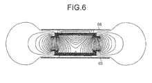
- FIG. 6 illustrates, for comparison, a distribution of magnetic field lines of a single both-sides wound coil, alone, which performs the power transfer of 12.5 kW.
- 65 and 66 are aluminum plates for magnetic shielding.
- the coupled and both-sides wound coil in which the two single both-sides wound coils are combined has the power transfer capability that is double the power transfer capability of the single both-sides wound coil, alone.
- the strengths of the leakage magnetic fields generated from the end portions become substantially similar to that generated by the single both-sides wound coil, alone.
- a single both-sides wound coil with small capacity is used as the single both-sides wound coil used for the coupled and both-sides wound coil, and an even number of a plurality of such a single both-sides wound coil are combined. Consequently, it becomes capable of reducing the leakage magnetic field of the coupled and both-sides wound coil. Further, by increasing a number of single both-sides wound coils to be combined, the capacity of the coupled and both-sides wound coil can be increased proportional to the number of the single both-sides wound coil, even if the capacity of each of the both-sides wound coils are small.
- FIGS. 9A and 9B illustrate results of measurements of the leakage magnetic field of the coupled and both-sides wound coil (the power transfer capability of each of the single both-sides wound coil, alone, is 6.2 kW) that performs power transfer of 12.5 kW by combining the two single both-sides wound coils.
- the center of the two single both-sides wound coils that are combined with each other is taken as a reference point.
- the relationship between the leakage magnetic flux density ( ⁇ T) and a distance from the reference point to a point in the x-direction or a point in the y-direction is obtained, and the result is illustrated in FIG. 9B .
- FIGS. 10A and 10B illustrate, for comparison, results of measurements of the leakage magnetic field of a single both-sides wound coil, alone, that performs the power transfer of 10 kW.
- a center of the single both-sides wound coil is taken as a reference point.
- the relationship between the leakage magnetic flux density ( ⁇ T) and a distance from the reference point to a point in the x-direction or a point in the y-direction is obtained, and the result is illustrated in FIG. 10B .
- the leakage magnetic flux in the coupled and both-sides wound coil in which the two single both-sides wound coils are combined is larger than the power transfer power of the single both-sides wound coil, alone, that performs the power transfer of 10 kW
- the leakage magnetic flux is lower than that of the single both-sides wound coil, alone.
- the decrease ratio of the leakage magnetic flux in the coupled and both-sides wound coil is apparent at a position greater than or equal to 500 mm away from the reference point (transformer center).
- the leakage magnetic flux of the coupled and both-sides wound coil is small are because: the power transfer power of each of the single both-sides wound coils configuring the coupled and both-sides wound coil is lower than the single both-sides wound coil, alone, having the power transfer capability of 10kW; and/or the leakage magnetic fluxes of the two single both-sides wound coils cancel each other. Further, the reason why the power transfer power of the coupled and both-sides wound coil is large is because the power transfer capability of the single both-sides wound coil with small capacity is doubled and exceeds 10 kW.
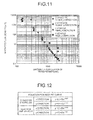
- FIG. 12 represents an equation of a best fit curve of change in magnetic flux density within a range of greater than or equal to 500 mm from the transformer center in FIG. 11 .
- the decrease in the leakage magnetic flux of the coupled and both-sides wound coil is apparent not only in the x-direction, which is the arrangement direction of the two single both-sides wound coils, but also apparent in the y-direction.
- the leakage magnetic flux decreases approximately by the fourth power of the distance from the reference point.
- ICNIRP International Commission on Non-ionizing Radiation Protection
- a single both-sides wound coil in which the leakage magnetic flux around the vehicle does not exceed the regulation value is selected when a coupled and both-sides wound coil in which two single both-sides wound coils are combined is installed at a install position at the bottom face of the vehicle.
- a desired capacity of the contactless power transfer transformer is divided by capacity of one of the single both-sides wound coils to obtain a required number of single both-sides wound coils.
- the single both-sides wound coils of the obtained number are combined to manufacture the coupled and both-sides wound coil.
- the coupled and both-sides wound coil may be configured by the both-sides wound coils of odd number (greater than or equal to three). Even when the both-sides wound coils of greater than or equal to three and of odd number are provided, the leakage magnetic fields by the consecutive single both-sides wound coils of the even number cancel each other, thereby the increase in the leakage magnetic field can be suppressed for a certain amount.
- a method for combining a required number of the single both-sides wound coils can reduce the leakage magnetic flux, and also can easily increase the capacity in accordance with the number of single both-sides wound coils combined. Therefore, the production operability is improved, and the reduction of the production cost can be decreased.
- winding wires of each of the two single both-sides wound coils in each of the pair are connected to each other in parallel, and winding wires of each of the pair of the both-sides wound coils are connected to each other in parallel.
- the currents are balanced by employing the series connection within the parallel connection.
- each width of the magnetic pole portions connected to each other can be set thinner without any problem, in order to reduce weight of the single both-sides wound coils or to shorten the coupled and both-sides wound coil.
Abstract
Description
- The present invention relates to a contactless power transfer transformer for a moving body, which transfers power to a moving body such as an electrical vehicle in a contactless manner. The present invention relates to a transformer that can easily increase its capacity while avoiding influence on health due to magnetic field exposure, as well as that is compatible with different types of contactless power transfer transformer.
- As a system for charging a battery of an electric vehicle or a plug-in hybrid car, there has been developing a method that transfers power to the vehicle in contactless manner by using electromagnetic induction, as illustrated in
FIG. 18 . Such a method transfers power from a primary transformer (power transmission coil) 10 installed on the ground to a secondary transformer (power reception coil) 20 of the contactless power transfer transformer, installed on a floor of the vehicle. - In the following
Patent Literature 1, as the power transmission coil and the power reception coil of the contactless power transfer transformer used in this system, there is disclosed a configuration in which an electric wiring is wound in a flattened circle and provided on one face of a flat plate ferritemagnetic core FIGS. 19A and 19B . Such a coil is referred to as "one-side wound coil" since thewinding wires 22, 23 are wound only at one side of the ferritemagnetic cores FIG. 19A is a cross sectional view of the power transmission coil and the power reception coil, andFIG. 19B is a plan view of the power transmission coil and the power reception coil. - The power transfer efficiency of the contactless power transfer transformer that uses the one-side wound coil largely decreases when a vehicle is stopped at a position different from a vehicle stop position and the power transmission coil and the power reception coil do not oppose each other, or when a gap between the power transmission coil and the power reception coil changes. In order to increase the permissible amount with respect to the positional variation or the gap variation, it becomes necessary to increase the sizes of the power transmission coil and the power reception coil.
- In the following
Patent Literature 2, there is disclosed a contactless power transfer transformer with large permissible amount for the positional variation and the gap variation and that can be configured small in size. As illustrated inFIGS. 20A and 20B , in such a contactless power transfer transformer, the power transmission coil and the power reception coil are configured by winding thewinding wires ferrite cores FIG. 20B , the "square core" is used as theferrite cores FIG. 20A is a cross sectional view of the power transmission coil and the power reception coil, andFIG. 20B is a plan view of the power transmission coil and the power reception coil. - In the contactless power transfer transformer, a main magnetic flux 67 that circles around the magnetic pole portions of the
ferrite cores magnetic fluxes magnetic fluxes magnetic fluxes good conductors - Further, in the following Patent Literature 3, in order to further decrease a size and weight of the both-sides wound coil, there is disclosed a power transmission coil and a power reception coil as illustrated in
FIGS. 21A to 21F . According to such a power transmission coil and a power reception coil, a ferrite core is configured in H-shape,parts winding wire 50 is wound around a part 43 (the part connects between the magnetic pole portions, and is also referred to as a wound portion) corresponding to a horizontal pole of the H-shape.FIG. 21A is a state in which the windingwire 50 is wound around theferrite core 40, andFIG. 21D is a state in which the windingwire 50 is not wound around theferrite core 40. Further,FIG. 21B is a cross sectional view taken along a line A-A ofFIG. 21A, and FIG. 21C is a cross sectional view taken along a line B-B ofFIG. 21A . Similarly,FIG. 21E is a cross sectional view taken along a line A-A ofFIG. 21D, and FIG. 21F is a cross sectional view taken along a line B-B ofFIG. 21D . - Here, a case is considered in which the power transmission coil and the power reception coil each configured by a both-sides wound coil by using this H-shape core are arranged to oppose each other with a spacing therebetween at a normal gap length of 70 mm and the power transfer of 3 kW is performed. In such a case, the following power transfer properties are obtained. In particular, the efficiency of the transformer is 95 %, the permissible amount of positional variation in the left and right direction (y-direction in
FIG. 21A ) is ±150 mm, the permissible amount of positional variation in the front and back direction (x-direction inFIG. 21A ) is ±60 mm, and the efficiency at which the normal gap length is increased to 100 mm is 92 %. -
- Patent Literature 1: Japanese Patent Application Laid-open No.
2008-87733 - Patent Literature 2: Japanese Patent Application Laid-open No.
2010-172084 - Patent Literature 3: Japanese Patent Application Laid-open No.
2011-50127 - For the contactless power transfer of the moving body, fast charge that enables the power transfer at short time and power transfer targeting large electric vehicles are desired. In this regard, it is necessary to increase capacity of the contactless power transfer transformer. However, in order to increase the capacity, it is necessary to take into account the influence of a leakage magnetic field on human body and/or the like.
- According to the contactless power transfer transformer that uses the both-sides wound coil, the permissible amount of the positional variation, the gap variation between the power transmission coil and the power reception coil, and/or the like is large. This means that, from a slightly different angle, the magnetic field (leakage magnetic field) diffusing to the surrounding is larger than the one-side wound coil.
- Therefore, for the contactless power transfer transformer that uses the both-sides wound coil, it is particularly necessary to take care of the leakage magnetic field.
- The present invention is made in view of the foregoing, and an object of the present invention is to provide a contactless power transfer transformer for a moving body, which is capable of increasing capacity of the transformer while suppressing the leakage magnetic field.
- According to the present invention, a contactless power transfer transformer for a moving body includes a power transmission coil and a power reception coil. The power reception coil is installed at a position at which the moving body is installed (e.g., as illustrated in
FIG. 18 ). Contactless power transfer is performed when the moving body is moved to a power transfer position at which the power transmission coil and the power reception coil oppose each other. At least one of the power transmission coil and the power reception coil is configured a coupled and both-sides wound coil. The coupled and both-sides wound coil is configured by combining a plurality of single both-sides wound coils. A winding wire is wound around a wound portion between magnetic pole portions of a core in each of the single both-sides wound coils. In the coupled and both-sides wound coil, the single both-sides wound coils are combined so that each wound portion of the single both-sides wound coils is arranged linearly with respect to each other, one of the magnetic pole portions of one of the single both-sides wound coils is connected to one of the magnetic pole portions of adjacent one of the single both-sides wound coils, and directions of magnetic fluxes in a vertical direction toward a corresponding coil from each of the magnetic pole portions connected to each other are identical. Each of the single both-sides wound coils is selected so that a leakage magnetic flux around the moving body of when the coupled and both-sides wound coil configured by two single both-sides wound coils is arranged at the install position of the moving body does not exceed a predetermined value. A number of the single both-sides wound coils configuring the coupled and both-sides wound coil is set so that a value obtained by multiplying power transfer capacity of one of the selected single both-sides wound coils by the number satisfies power transfer capacity of the contactless power transfer transformer. - According to the coupled and both-sides wound coil configured by the two single both-sides wound coils, the leakage magnetic fields generated by each of the single both-sides wound coils cancel each other at a location far away. Thus, the strength of the leakage magnetic field largely decreases. The principle therebehind is considered similar to the principle in which the attenuation characteristic of the leakage magnetic field is good for the one-side wound coil of
FIG. 19 . Therefore, when the single both-sides wound coil that configures the coupled and both-sides wound coil is selected, a coupled and both-sides wound coil configured by two single both-sides wound coils are placed at an install position, and single both-sides wound coils that satisfy a condition of leakage magnetic field is selected. A number of the single both-sides wound coils to be used for the coupled and both-sides wound coil is desired to be an even number in order to reduce the leakage magnetic flux. However, if the leakage magnetic field is not an issue, the coupled and both-sides wound coil may be configured by an odd number of the single both-sides wound coils. - Further, in the contactless power transfer transformer for the moving body of the present invention, the power reception coil configured by the coupled and both-sides wound coil can be installed at an install position at a bottom face of the moving body so that an arrangement direction of the single both-sides wound coils in the coupled and both-sides wound coil coincides with a front and back direction of the moving body.
- According to the both-sides wound coil, the permissible amount of the positional variation in a direction parallel to a pair of the magnetic pole portions is smaller than the permissible amount of the positional variation in a direction (i.e., an array direction of the both-sides wound coils) perpendicular to the pair of the magnetic pole portions. Therefore, a front and back direction of the moving body, which is a direction easier to provide solutions (for example, a tire block) for preventing the positional variation, can be made to coincide with a direction toward which the permissible level of the positional variation is low.
- Further, in the contactless power transfer transformer for the moving body of the present invention, each of the single both-sides wound coils may include an H-shape core in which the wound portion is arranged at a middle part between a pair of the parallel magnetic pole portions.
- By using the H-shape core, an amount of ferrite is reduced, and it becomes capable of reducing the weight, the size, and the cost. Further, the length of the magnetic pole portion (the length of the H-shape in the longitudinal direction) can be increased to increase the permissible amount of the positional variation or the gap variation.
- Further, in the contactless power transfer transformer for the moving body of the present invention, if a width in the arrangement direction of the single both-sides wound coils of the coupled and both-sides wound coil and obtained by adding widths of the connected magnetic pole portions (width of the single both-sides wound coil in the arrangement direction) is D1, and if a width of the magnetic pole portion positioned at an end portion of the coupled and both-sides wound coil is D2, D1<2×D2 to shorten the length of the coupled and both-sides wound coil in the arrangement direction.
- At the position at which the single both-sides wound coils are adjacent to each other, the width becomes doubled since the magnetic pole portions of the two single both-sides wound coils are connected with each other. Therefore, a width of a single magnetic pole portion may be thin.
- Further, in the contactless power transfer transformer for the moving body of the present invention, the power transmission coil and the power reception coil may each be configured by the coupled and both-sides wound coil that is configured by combining the two single both-sides wound coils, in the coupled and both-sides wound coil of one of the power transmission coil and the power reception coil, winding wires of the two single both-sides wound coils may be electrically connected to each other in series, and in the coupled and both-sides wound coil of other one of the power transmission coil and the power reception coil, the winding wires of the two both-sides wound coils may be electrically connected to each other in parallel.
- When winding wires of a plurality of the single both-sides wound coils that configure the power transmission coil and the power reception coil are connected only in series, the currents flowing through the winding wires connected in series become the same. Therefore, even if the position varies between the power transmission coil and the power reception coil, the power of the power transfer of each of the single both-sides wound coils is hardly unbalanced. However, the voltage becomes high, and therefore, it is difficult to handle. On the other hand, if the winding wires of the plurality of the single both-sides wound coils are connected only in parallel, the voltage becomes low, but the power of the power transfer of each of the both-sides wound coils is unbalanced when the position variation occurs. Therefore, by combining the series and the parallel connections, the current can be balanced while suppressing the increase in the voltage.
- Further, in the contactless power transfer transformer for the moving body of the present invention, the power transmission coil and the power reception coil may each be configured by the coupled and both-sides wound coil that is configured by combining m pairs of the two single both-sides wound coils, in the coupled and both-sides wound coil of one of the power transmission coil and the power reception coil, the winding wires of each of the two single both-sides wound coils in each of the m pairs of the two single both-sides wound coils may be electrically connected to each other in series, and winding wires of each of the m pairs of the two single both-sides wound coils may be electrically connected to each other in parallel, and in the coupled and both-sides wound coil of other one of the power transmission coil and the power reception coil, the winding wires of each of the two single both-sides wound coils in each of the m pairs of the two single both-sides wound coils may be electrically connected to each other in parallel, and the winding wires of each of the m pairs of the two single both-sides wound coils may be electrically connected to each other in parallel.
- By putting the series connection in the parallel connection, the current can be balanced.
- Further, in the contactless power transfer transformer for the moving body of the present invention, the power transmission coil and the power reception coil may both be configured by the coupled and both-sides wound coil configured by combining m pairs of the two single both-sides wound coils, and in the coupled and both-sides wound coil, the winding wires of each of the two single both-sides wound coils in each of the m pairs of the two single both-sides wound coils may be electrically connected to each other in series, and the winding wires of each of the m pairs of the single both-sides wound coils are electrically connected to each other in parallel.
- By putting the series connection in the parallel connection, the currents can be balanced.
- Further, in the contactless power transfer transformer for the moving body of the present invention, one of the power transmission coil and the power reception coil may be configured by the coupled and both-sides wound coil that is configured by combining the two single both-sides would coils, and other one of the power transmission coil and the power reception coil may be configured by a one-side wound coil in which an electric wire is wound in a flattened circle at one face of a flattened plate ferrite magnetic core.
- As described above, the coupled and both-sides wound coil that is configured by combining the two single both-sides wound coils can perform the power transfer not only with respect to the same type of coupled and both-sides wound coil but also with respect to one-side wound coil.
- According to a contactless power transfer transformer for a moving body of the present invention, capacity can easily be increased while suppressing the leakage magnetic field. Further, it is possible to perform power transfer not only with respect to the same type of both-sides wound coil but also with respect to different type of one-side wound coil. Therefore, the contactless power transfer transformer for a moving body of the present invention is compatible with the one-side wound coil.
-
-
FIG. 1A is a diagram illustrating a state in which single both-sides wound coils each having a winding wire direction opposite each other are connected to each other in series, in a contactless power transfer transformer according to an embodiment. -
FIG. 1B is a diagram illustrating a state in which single both-sides wound coils each having the same winding wire direction are connected to each other in series, in the contactless power transfer transformer according to the embodiment. -
FIG. 2 is a diagram illustrating a main magnetic flux of the contactless power transfer transformer according to the embodiment. -
FIG. 3A is a diagram illustrating a state in which single both-sides wound coils each having a winding wire direction opposite each other are connected to each other in parallel, in the contactless power transfer transformer according to the embodiment. -
FIG. 3B is a diagram illustrating a state in which single both-sides wound coils each having the same winding wire direction are connected to each other in parallel, in the contactless power transfer transformer according to the embodiment. -
FIG. 4 is a diagram illustrating a direction in which a power reception coil is attached to a vehicle, according to the embodiment. -
FIG. 5 is a diagram illustrating a distribution of magnetic field lines of a coupled and both-sides wound coil in the contactless power transfer transformer according to the embodiment. -
FIG. 6 is a diagram illustrating a distribution of magnetic field lines of a single both-sides wound coil, alone. -
FIG. 7A is a plan view illustrating a configuration of the single both-sides wound coil. -
FIG. 7B is a side view of when the single both-sides wound coils are arranged opposite each other. -
FIG. 7C is a diagram for explaining a case when the single both-sides wound coils are arranged opposite each other, and illustrating one of the single both-sides wound coils arranged opposite each other as a cross sectional diagram. -
FIG. 8 is a diagram for explaining a state in which electrical power of power transfer does not increase even when the single both-sides wound coils are connected. -
FIG. 9A is a diagram illustrating a configuration of the coupled and both-sides wound coil in the contactless power transfer transformer according to the embodiment for measuring the leakage magnetic flux density. -
FIG. 9B is a diagram illustrating a measurement result of the leakage magnetic flux density of the coupled and both-sides wound coil ofFIG. 9A . -
FIG. 10A is a diagram illustrating a configuration of the single both-sides wound coil, alone, for measuring the leakage magnetic flux density. -
FIG. 10B is a diagram for illustrating a measurement result of the leakage magnetic flux density in the single both-sides wound coil, alone, ofFIG. 10A . -
FIG. 11 is a graph comparing the measurement results ofFIGS. 9B and10B . -
FIG. 12 is a diagram illustrating an equation indicating a best fit curve of a change in the magnetic flux density ofFIG. 11 . -
FIG. 13A is a diagram illustrating change in property in accordance with a positional variation in x-direction in the contactless power transfer transformer according to the embodiment. -
FIG. 13B is a diagram illustrating change in property in accordance with the positional variation in y-direction in the contactless power transfer transformer according to the embodiment. -
FIG. 13C is a diagram illustrating change in property in accordance with a variation in a gap length in the contactless power transfer transformer according to the embodiment. -
FIG. 14A is a diagram illustrating a mode of electric connection of the coupled and both-sides wound coil configured by the single both-sides wound coils of "2times 2 pairs". -
FIG. 14B is a diagram illustrating another example of the mode of the electric connection of the coupled and both-sides wound coil configured by the single both-sides wound coils of "2times 2 pairs". -
FIG. 15A is a diagram illustrating still another example of the mode of the electric connection of the coupled and both-sides wound coil configured by the single both-sides wound coils of "2times 2 pairs". -
FIG. 15B is a diagram illustrating still another example of the mode of the electric connection of the coupled and both-sides wound coil configured by the single both-sides wound coils of "2times 2 pairs". -
FIG. 16 is a diagram illustrating a modification in which widths of the connected magnetic pole portions of the coupled and both-sides wound coil are decreased. -
FIG. 17A is a cross sectional view illustrating the contactless power transfer transformer in which the coupled and both-sides wound coil and a one-side wound coil oppose each other. -
FIG. 17B is a plan view ofFIG. 17A . -
FIG. 18 is a diagram illustrating a contactless power transfer system for a car. -
FIG. 19A is a cross sectional view illustrating a conventional one-side wound coil. -
FIG. 19B is a plan view ofFIG. 19A . -
FIG. 20A is a cross sectional view illustrating a both-sides wound coil which uses a conventional square core. -
FIG. 20B is a plan view ofFIG. 20A . -
FIG. 21A is a diagram explaining a both-sides wound coil which uses a conventional H-shape core, and illustrating a state in which a winding wire is wound. -
FIG. 21B is a cross sectional view taken along a line A-A ofFIG. 21A . -
FIG. 21C is a cross sectional view taken along a line B-B ofFIG. 21A . -
FIG. 21D is a diagram explaining a both-sides wound coil which uses a conventional H-shape core, and illustrating a state in which a winding wire is not wound. -
FIG. 21E is a cross sectional view taken along a line A-A ofFIG. 21D . -
FIG. 21F is a cross sectional view taken along a line B-B ofFIG. 21D . -
FIG. 1A and FIG. 1B schematically illustrates a power transmission coil of a moving body contactless power transfer transformer according to an embodiment of the present embodiment. A power reception coil has the same configuration. - The power transmission coil is configured by a coupled and both-sides wound coil in which two single both-sides wound
coils - The single both-sides wound
coils FIGS. 7A and 7B , the H-shape core is configured by: a pair ofmagnetic pole cores 80 that are parallel to each other; and a windingwire core 81 that is orthogonal to themagnetic pole cores 80. Both themagnetic pole cores 80 and the windingwire core 81 are ferrite cores. - A winding
wire portion 50 around which an electric wire is wound is attached at the middle of the windingwire core 81. Both ends of a ferrite plate protruding from both sides of the windingwire portion 50 are connected to themagnetic pole cores 80 via bottom-layer ferrite plates 82. - As illustrated in
FIG. 7C , the bottom-layer ferrite plates 82 are laminated at a side opposing a corresponding coil so as to raise a height of the upper most portion of themagnetic pole cores 80 to the height of the windingwire portion 50 or greater. Themagnetic pole cores 80 are arranged above the bottom-layer ferrite plate. - As described above, the "legs" formed by the bottom-
layer ferrite plate 82 is attached to the magnetic pole parts of themagnetic pole cores 80. Accordingly, a magnetic gap length G2 can be set to a length the same as a length of spacing G1 of the windingwire portion 50 or shorter. As described above, by making the magnetic gap length short, a coupling coefficient between the coils becomes high and the power transfer efficiency and the maximum power transfer power increase. - As illustrated in
FIGS. 1A and 1B , in the two single both-sides woundcoils magnetic pole core 180 of the single both-sides woundcoil 100 is arranged and connected to amagnetic pole core 280 of an adjacent single both-sides woundcoil 200. Further, a windingwire core 181 of the single both-sides woundcoil 100 is combined with a windingwire core 281 of the adjacent single both-sides woundcoil 200 so as to be next to each other in linear manner. -
FIG. 2 illustrates a main magnetic flux between thepower transmission coil 10 and thepower reception coil 20 which are each configured by a coupled and both-sides wound coil in which two single both-sides wound coils are combined. In each of thepower transmission coil 10 and thepower reception coil 20, currents flow such that: a direction of the main magnetic flux through the windingwire core 181 is opposite a direction of the main magnetic flux through the windingwire core 281; and directions of the main magnetic fluxes to the opposing coil from each of themagnetic pole cores - As described above, the directions of the main magnetic fluxes in the vertical direction toward the corresponding coil from the
magnetic pole cores power transmission coil 10 and thepower reception coil 20 becomes stronger, and the power transfer power increases. The power transfer power of the coupled and both-sides wound coil in which a plurality of single both-sides wound coils are combined increases as a number of the both-sides wound coils increases, in proportional manner. - On the other hand, in the coupled and both-sides wound coil in which the two single both-sides wound coils are combined with each other, the leakage magnetic fields generated by each of the single both-sides wound coils cancel each other at a location far away. Thus, the strength of the leakage magnetic field largely decreases.
- Here, as illustrated in
FIG. 8 , if the direction of the main magnetic flux in the vertical direction toward the corresponding coil from themagnetic pole core 180 is opposite the direction of the main magnetic flux in the vertical direction toward the corresponding coil from themagnetic pole core 280, the main magnetic fluxes in the vertical direction cancel each other. Thus, even if a plurality of the single both-sides wound coils are combined, the power transfer power cannot be increased. -
FIG. 1A illustrates a case in which winding wires of the two single both-sides woundcoils coils FIG. 1B illustrates a case in which the winding wires of the two single both-sides woundcoils coils - Further,
FIG. 3A illustrates a case in which winding wires of the two single both-sides woundcoils coils FIG. 3B illustrates a case in which the winding wires of the two single both-sides woundcoils coils - As illustrated in
FIG. 4 , the power reception coil configured by the coupled and both-sides wound coil is installed at an install position on an underfloor surface of the vehicle such that an arrangement direction of the single both-sides wound coils coincides with a back and front direction of the vehicle. -
FIG. 5 illustrates a distribution of magnetic field lines of the coupled and both-sides wound coil in which the two single both-side wound coils are combined, and is examined by using a magnetic field analyzing software (JMAG-Designer Ver. 11.0). Here, the distribution is of a coupled and both-sides wound coil that performs power transfer of 25 kW by combining two single both-sides wound coils having power transfer capability of 12.5 kW.FIG. 6 illustrates, for comparison, a distribution of magnetic field lines of a single both-sides wound coil, alone, which performs the power transfer of 12.5 kW. 65 and 66 are aluminum plates for magnetic shielding. - In the coupled and both-sides wound coil in which the two single both-sides wound coils are combined, leakage magnetic fields generated from the magnetic cores at both ends of the coupled and both-sides wound coil are the same as that of the single both-sides would coil, alone. However, the leakage magnetic fields generated from the positions of the magnetic pole cores that are connected with each other is weak at a location sufficiently far away because the leakage magnetic fields generated by each of the both-sides wound coils cancel each other at the location sufficiently far away.
- Therefore, the coupled and both-sides wound coil in which the two single both-sides wound coils are combined has the power transfer capability that is double the power transfer capability of the single both-sides wound coil, alone. Thus, the strengths of the leakage magnetic fields generated from the end portions become substantially similar to that generated by the single both-sides wound coil, alone.
- Therefore, a single both-sides wound coil with small capacity is used as the single both-sides wound coil used for the coupled and both-sides wound coil, and an even number of a plurality of such a single both-sides wound coil are combined. Consequently, it becomes capable of reducing the leakage magnetic field of the coupled and both-sides wound coil. Further, by increasing a number of single both-sides wound coils to be combined, the capacity of the coupled and both-sides wound coil can be increased proportional to the number of the single both-sides wound coil, even if the capacity of each of the both-sides wound coils are small.
-
FIGS. 9A and 9B illustrate results of measurements of the leakage magnetic field of the coupled and both-sides wound coil (the power transfer capability of each of the single both-sides wound coil, alone, is 6.2 kW) that performs power transfer of 12.5 kW by combining the two single both-sides wound coils. As illustrated inFIG. 9A , in the measurement, the center of the two single both-sides wound coils that are combined with each other is taken as a reference point. The relationship between the leakage magnetic flux density (µT) and a distance from the reference point to a point in the x-direction or a point in the y-direction is obtained, and the result is illustrated inFIG. 9B . - Further,
FIGS. 10A and 10B illustrate, for comparison, results of measurements of the leakage magnetic field of a single both-sides wound coil, alone, that performs the power transfer of 10 kW. As illustrated inFIG. 10A , in the measurement, a center of the single both-sides wound coil is taken as a reference point. Then, the relationship between the leakage magnetic flux density (µT) and a distance from the reference point to a point in the x-direction or a point in the y-direction is obtained, and the result is illustrated inFIG. 10B . - Further,
FIG. 11 summarizes the measurement results ofFIGS. 9B and10B as a graph. - As is clear from
FIG. 11 , although the power transfer power of the coupled and both-sides wound coil in which the two single both-sides wound coils are combined is larger than the power transfer power of the single both-sides wound coil, alone, that performs the power transfer of 10 kW, the leakage magnetic flux is lower than that of the single both-sides wound coil, alone. The decrease ratio of the leakage magnetic flux in the coupled and both-sides wound coil is apparent at a position greater than or equal to 500 mm away from the reference point (transformer center). - The reasons why the leakage magnetic flux of the coupled and both-sides wound coil is small are because: the power transfer power of each of the single both-sides wound coils configuring the coupled and both-sides wound coil is lower than the single both-sides wound coil, alone, having the power transfer capability of 10kW; and/or the leakage magnetic fluxes of the two single both-sides wound coils cancel each other. Further, the reason why the power transfer power of the coupled and both-sides wound coil is large is because the power transfer capability of the single both-sides wound coil with small capacity is doubled and exceeds 10 kW.
-
FIG. 12 represents an equation of a best fit curve of change in magnetic flux density within a range of greater than or equal to 500 mm from the transformer center inFIG. 11 . The decrease in the leakage magnetic flux of the coupled and both-sides wound coil is apparent not only in the x-direction, which is the arrangement direction of the two single both-sides wound coils, but also apparent in the y-direction. The leakage magnetic flux decreases approximately by the fourth power of the distance from the reference point. - Currently, from the point of view of preventing the health injury due to the magnetic field exposure, there are provided various regulations and standards for the leakage magnetic field. For example, the International Commission on Non-ionizing Radiation Protection (ICNIRP) has published "Reference Levels for General Public Exposure to Time-varying Electric and Magnetic fields (2010)", and specified a value of 2.7×10⁻⁵ T as a magnetic flux density within a frequency range between 3 kHz and 10 MHz.
- A contactless power transfer transformer that satisfies the above-mentioned standards, further satisfies strict regulation value of the leakage magnetic flux specified within the corporation, and has a desired capacity, can be manufactured by the following steps.
- A single both-sides wound coil in which the leakage magnetic flux around the vehicle does not exceed the regulation value is selected when a coupled and both-sides wound coil in which two single both-sides wound coils are combined is installed at a install position at the bottom face of the vehicle. Next, a desired capacity of the contactless power transfer transformer is divided by capacity of one of the single both-sides wound coils to obtain a required number of single both-sides wound coils. Then, the single both-sides wound coils of the obtained number are combined to manufacture the coupled and both-sides wound coil.
- At this time, it is important that the number of the single both-sides wound coils combined in the coupled and both-sides wound coil is set to be an even number in order to reduce the leakage magnetic flux. If the leakage magnetic field is not of an issue, then the coupled and both-sides wound coil may be configured by the both-sides wound coils of odd number (greater than or equal to three). Even when the both-sides wound coils of greater than or equal to three and of odd number are provided, the leakage magnetic fields by the consecutive single both-sides wound coils of the even number cancel each other, thereby the increase in the leakage magnetic field can be suppressed for a certain amount.
- As described above, a method for combining a required number of the single both-sides wound coils can reduce the leakage magnetic flux, and also can easily increase the capacity in accordance with the number of single both-sides wound coils combined. Therefore, the production operability is improved, and the reduction of the production cost can be decreased.
- The leakage magnetic field at the outer perimeter of the vehicle of when the coupled and both-sides wound coil used for the measurement of the leakage magnetic field of
FIG. 9B is installed at the install position at the center and the bottom of the vehicle sufficiently satisfies the reference levels of the ICNIRP. - Further,
FIGS. 13A to 13C illustrates changes in properties in accordance with a positional variation and a gap variation between the power transmission coil and the power reception coil comprised in the coupled and both-sides wound coil.FIG. 13A illustrates change in a power transfer power (PD), a power transfer efficiency (η), an input voltage (VIN), a coupling coefficient (k) and an output voltage (V2) of when a position is changed within a range of ±60 mm in the x-direction.FIG. 13B illustrates change in each value of when a position is changed within a range of ±150 mm in the y-direction.FIG. 13C illustrates change in each value of when the gap length is changed within a range between 40 mm and 90 mm. Here, the input voltage (VIN) is adjusted so that PH is at constant. - As is clear from
FIGS. 13A to 13C , the contactless power transfer transformer permits large positional variation and gap variation. - In the coupled and both-sides wound coil, the winding wires of the plurality of the single both-sides wound coils can be connected to each other in series or in parallel, as illustrated in
FIGS. 1A, 1B ,3A, and 3B . In case when the winding wires of the single both-sides woundcoils FIGS. 1A and 1B , the same current flows through both winding wires. Thus, if positions of the power transmission coil and the power reception coil comprised in the coupled and both-sides wound coil differ from each other, the unbalance of the current in the both-side wound coils 100, and 200 will not be caused. However, if the winding wires are connected in series, the voltage between the terminals becomes high. - On the other hand, if the winding wires of the single both-sides wound
coils FIGS. 3A and 3B , the voltage between the terminals is reduced to 1/2 of that of when the winding wires of the single both-sides wound coils are connected to each other in series. Accordingly, it can easily be handled. However, if positions of the power transmission coil and the power reception coil comprised in the coupled and both-sides wound coil differ from each other, the current flowing through the both-sides woundcoils - Therefore, it is preferred to connect the winding wires of the two single both-sides wound coils in one of the power transmission coil and the power reception coil in series and the winding wires of the two single both-sides wound coils in other one of the power transmission coil and the power reception coil in parallel so as to balance the currents.
- Further, as illustrated in
FIGS. 14A and 14B , the coupled and both-sides wound coil can be configured by combining a pair of two single both-sides wound coils in the following manner. In particular, in one of the power transmission coil and the power reception coil, as illustrated inFIG. 14A , winding wires of each of the two both-sides wound coils in each of the pair are connected to each other in series, and winding wires of each of the pair of the single both-sides wound coils are connected to each other in parallel. Further, in other one of the power transmission coil and the power reception coil, as illustrated inFIG. 14B , winding wires of each of the two single both-sides wound coils in each of the pair are connected to each other in parallel, and winding wires of each of the pair of the both-sides wound coils are connected to each other in parallel. In such a case, the currents are balanced by employing the series connection within the parallel connection. - Further, as illustrated in
FIGS. 15A and 15B , the coupled and both-sides wound coil can be configured by combining a pair of the two single both-sides wound coils in the following manner. In particular, as illustrated inFIGS. 15A and 15B , in the power transmission coil and the power reception coil, winding wires of each of the two single both-sides wound coils in each of the pair are connected to each other in series. Further, winding wires of each of the pair of the single both-sides wound coils are connected to each other in series. In such a case, the currents can be balanced by employing the series connection within the parallel connection. - In
FIGS. 14A, 14B, 15A, and 15B , the pair of the two single both-sides wound coils are mentioned. However, the pair can be greater than or equal to one pair (m number of pairs: m is a natural number). - Further, as illustrated in
FIG. 16 , in the coupled and both-sides wound coil, a width D1 (width of the both-sides wound coils in the arrangement direction) obtained by adding the widths of the magnetic pole portions that are connected to each other can be set to D1<2×D2 where D2 is a width of the magnetic pole portion positioned at an end portion of the coupled and both-sides wound coil. - The width becomes double at the position at which the single both-sides wound coils are adjacent to each other because the magnetic pole portions of the two single both-sides wound coils are connected to each other. Therefore, each width of the magnetic pole portions connected to each other can be set thinner without any problem, in order to reduce weight of the single both-sides wound coils or to shorten the coupled and both-sides wound coil.
- Further, as illustrated in
FIGS. 17A and 17B , even when the coupled and both-sides wound coil in which the two single both-sides woundcoils electric wire 22 is wound at one side of a flat-plate-like ferritemagnetic core 21 in flat manner, a main magnetic flux circulating between the coupled and both-sides wound coil and the one-side wound coil as illustrated inFIG. 17A is generated. Therefore, efficient contactless power transfer can be performed therebetween. Thus, the coupled and both-sides wound coil in which the both-sides woundcoils FIG. 17B is a plan view ofFIG. 17A . - In the above, it is explained a case in which the single both-sides wound coil has the H-shape core. However, as illustrated in
FIG. 20B , the single both-sides wound coil may have a square shape core. - A contactless power transfer transformer according to the present invention can increase capacity while maintaining the leakage magnetic field low. Thus, the contactless power transfer transformer can widely be used for contactless power transfer with respect to various moving bodies such as an electric vehicle or a plug-in hybrid car.
-
- 10
- POWER TRANSMISSION COIL
- 20
- POWER RECEPTION COIL
- 21
- FERRITE MAGNETIC CORE
- 31
- FERRITE MAGNETIC CORE
- 40
- H-SHAPE FERRITE CORE
- 41
- MAGNETIC POLE PORTION
- 42
- MAGNETIC POLE PORTION
- 43
- WOUND PORTION
- 50
- WINDING WIRE PORTION
- 61
- SQUARE FERRITE CORE
- 62
- WINDING WIRE
- 63
- SQUARE FERRITE CORE
- 64
- WINDING WIRE
- 65
- ALUMINUM PLATE
- 66
- ALUMINUM PLATE
- 67
- MAIN MAGNETIC FLUX
- 68
- LEAKAGE MAGNETIC FLUX
- 69
- LEAKAGE MAGNETIC FLUX
- 80
- MAGNETIC POLE CORE
- 81
- WINDING WIRE CORE
- 82
- LOWER LAYER FERRITE PLATE
- 100
- BOTH-SIDES WOUND COIL
- 150
- WINDING WIRE
- 180
- MAGNETIC POLE CORE
- 181
- WINDING WIRE CORE
- 200
- BOTH-SIDES WOUND COIL
- 250
- WINDING WIRE
- 280
- MAGNETIC POLE CORE
- 281
- WINDING WIRE CORE
Claims (8)
- A contactless power transfer transformer for a moving body, the contactless power transfer transformer including a power transmission coil and a power reception coil, the power reception coil being installed at a position at which the moving body is installed, contactless power transfer being performed when the moving body is moved to a power transfer position at which the power transmission coil and the power reception coil oppose each other, wherein
at least one of the power transmission coil and the power reception coil is configured by a coupled and both-sides wound coil, the coupled and both-sides wound coil being configured by combining a plurality of single both-sides wound coils, a winding wire being wound around a wound portion between magnetic pole portions of a core in each of the single both-sides wound coils,
in the coupled and both-sides wound coil, the single both-sides wound coils are combined so that each wound portion of the single both-sides wound coils is arranged linearly with respect to each other, one of the magnetic pole portions of one of the single both-sides wound coils is connected to one of the magnetic pole portions of adjacent one of the single both-sides wound coils, and directions of magnetic fluxes in a vertical direction toward a corresponding coil from each of the magnetic pole portions connected to each other are identical,
each of the single both-sides wound coils is selected so that a leakage magnetic flux around the moving body of when the coupled and both-sides wound coil configured by two single both-sides wound coils is arranged at the install position of the moving body does not exceed a predetermined value, and
a number of the single both-sides wound coils configuring the coupled and both-sides wound coil is set so that a value obtained by multiplying power transfer capacity of one of the selected single both-sides wound coils by the number satisfies power transfer capacity of the contactless power transfer transformer. - The contactless power transfer transformer for the moving body of Claim 1, wherein the power reception coil configured by the coupled and both-sides wound coil is installed at a install position at a bottom face of the moving body so that an arrangement direction of the single both-sides wound coils in the coupled and both-sides wound coil coincides with a front and back direction of the moving body.
- The contactless power transfer transformer for the moving body of Claim 1 or 2, wherein each of the single both-sides wound coils includes an H-shape core in which the wound portion is arranged at a middle part between a pair of the parallel magnetic pole portions.
- The contactless power transfer transformer for the moving body of Claim 3, wherein, if a width in the arrangement direction of the single both-sides wound coils of the coupled and both-sides wound coil and obtained by adding widths of the connected magnetic pole portions is D1, and if a width of the magnetic pole portion positioned at an end portion of the coupled and both-sides wound coil is D2, D1<2×D2.
- The contactless power transfer transformer for the moving body of any one of Claims 1 to 4, wherein
the power transmission coil and the power reception coil are each configured by the coupled and both-sides wound coil that is configured by combining the two single both-sides wound coils,
in the coupled and both-sides wound coil of one of the power transmission coil and the power reception coil, winding wires of the two single both-sides wound coils are electrically connected to each other in series, and
in the coupled and both-sides wound coil of other one of the power transmission coil and the power reception coil, the winding wires of the two both-sides wound coils are electrically connected to each other in parallel. - The contactless power transfer transformer for the moving body of any one of Claims 1 to 4, wherein,
the power transmission coil and the power reception coil are each configured by the coupled and both-sides wound coil that is configured by combining m pairs of the two single both-sides wound coils,
in the coupled and both-sides wound coil of one of the power transmission coil and the power reception coil, the winding wires of each of the two single both-sides wound coils in each of the m pairs of the two single both-sides wound coils are electrically connected to each other in series, and winding wires of each of the m pairs of the two single both-sides wound coils are electrically connected to each other in parallel, and
in the coupled and both-sides wound coil of other one of the power transmission coil and the power reception coil, the winding wires of each of the two single both-sides wound coils in each of the m pairs of the two single both-sides wound coils are electrically connected to each other in parallel, and the winding wires of each of the m pairs of the two single both-sides wound coils are electrically connected to each other in parallel. - The contactless power transfer transformer for the moving body of any one of Claims 1 to 4, wherein,
the power transmission coil and the power reception coil are both configured by the coupled and both-sides wound coil configured by combining m pairs of the two single both-sides wound coils, and
in the coupled and both-sides wound coil, the winding wires of each of the two single both-sides wound coils in each of the m pairs of the two single both-sides wound coils are electrically connected to each other in series, and the winding wires of each of the m pairs of the single both-sides wound coils are electrically connected to each other in parallel. - The contactless power transfer transformer for the moving body of Claim 1 or 2, wherein
one of the power transmission coil and the power reception coil is configured by the coupled and both-sides wound coil that is configured by combining the two single both-sides would coils, and
other one of the power transmission coil and the power reception coil is configured by a one-side wound coil in which an electric wire is wound in a flattened circle at one face of a flattened plate ferrite magnetic core.
Applications Claiming Priority (2)
| Application Number | Priority Date | Filing Date | Title |
|---|---|---|---|
| JP2012116090 | 2012-05-21 | ||
| PCT/JP2013/064133 WO2013176152A1 (en) | 2012-05-21 | 2013-05-21 | Contactless electrical-power-supplying transformer for moving body |
Publications (3)
| Publication Number | Publication Date |
|---|---|
| EP2854145A1 true EP2854145A1 (en) | 2015-04-01 |
| EP2854145A4 EP2854145A4 (en) | 2016-03-09 |
| EP2854145B1 EP2854145B1 (en) | 2018-03-28 |
Family
ID=49623840
Family Applications (1)
| Application Number | Title | Priority Date | Filing Date |
|---|---|---|---|
| EP13793139.0A Not-in-force EP2854145B1 (en) | 2012-05-21 | 2013-05-21 | Contactless electrical-power-supplying transformer for moving body |
Country Status (6)
| Country | Link |
|---|---|
| US (1) | US9793045B2 (en) |
| EP (1) | EP2854145B1 (en) |
| JP (1) | JP5885837B2 (en) |
| CN (2) | CN107039162A (en) |
| HK (1) | HK1206481A1 (en) |
| WO (1) | WO2013176152A1 (en) |
Families Citing this family (24)
| Publication number | Priority date | Publication date | Assignee | Title |
|---|---|---|---|---|
| GB2496187A (en) * | 2011-11-04 | 2013-05-08 | Bombardier Transp Gmbh | Providing a vehicle with electric energy using a receiving device for an alternating electromagnetic field |
| EP2953145A4 (en) * | 2013-01-30 | 2016-04-06 | Panasonic Ip Man Co Ltd | Contactless power transmission device |
| JP2014175514A (en) * | 2013-03-11 | 2014-09-22 | Yazaki Corp | Power feeding-side coil and non-contact power feeding apparatus |
| JP6410287B2 (en) * | 2014-02-10 | 2018-10-24 | 国立大学法人埼玉大学 | Contactless power supply system |
| JP6455798B2 (en) * | 2014-05-19 | 2019-01-23 | Tdk株式会社 | Coil unit |
| JP6323192B2 (en) * | 2014-06-12 | 2018-05-16 | 株式会社デンソー | Pad arrangement structure for power transmission and contactless power transmission system |
| DE102014215299A1 (en) * | 2014-08-04 | 2016-02-04 | Robert Bosch Gmbh | Method for the contactless charging or discharging of a battery-powered object |
| WO2016135894A1 (en) * | 2015-02-25 | 2016-09-01 | 株式会社 東芝 | Inductor unit and electric vehicle |
| WO2016160681A1 (en) * | 2015-03-29 | 2016-10-06 | Sanjaya Maniktala | Wireless power transfer using multiple coil arrays |
| JP6541425B2 (en) * | 2015-05-18 | 2019-07-10 | 株式会社テクノバ | Wireless power supply system |
| EP3157022A1 (en) * | 2015-10-16 | 2017-04-19 | SMA Solar Technology AG | Inductor assembly and power suppy system using the same |
| US10516304B2 (en) * | 2015-12-22 | 2019-12-24 | Intel Corporation | Wireless charging coil placement for reduced field exposure |
| US10411492B2 (en) | 2015-12-23 | 2019-09-10 | Intel Corporation | Wireless power transmitter shield with capacitors |
| CN105405622B (en) * | 2015-12-31 | 2017-10-03 | 浙江大学 | A kind of loose coupled transformer device for electric automobile wireless charging |
| US11239027B2 (en) | 2016-03-28 | 2022-02-01 | Chargedge, Inc. | Bent coil structure for wireless power transfer |
| US10566850B2 (en) | 2016-06-10 | 2020-02-18 | Witricity Corporation | Apparatus and methods for reducing magnetic field emissions between wireless power transmitters |
| JP7037549B2 (en) * | 2016-08-31 | 2022-03-16 | フィリップ・モーリス・プロダクツ・ソシエテ・アノニム | Wireless charging system for charging rechargeable electrical energy sources in heating devices for aerosol-generating articles |
| DE102016219491A1 (en) * | 2016-10-07 | 2018-04-12 | Bayerische Motoren Werke Aktiengesellschaft | Coil unit for inductive charging of a vehicle |
| JP6742219B2 (en) * | 2016-11-02 | 2020-08-19 | 日本無線株式会社 | Non-contact power transmission device |
| CN108461264B (en) * | 2018-02-09 | 2020-03-03 | 浙江大学 | Wireless power transmission loose magnetic coupling transformer device with large offset fault tolerance range and circuit thereof |
| WO2020003713A1 (en) * | 2018-06-26 | 2020-01-02 | 株式会社デンソー | In-motion contactless power supply system and contactless power supply device |
| CN109501608A (en) * | 2019-01-10 | 2019-03-22 | 张雁 | A kind of wireless electric vehicle charging device |
| JP7357310B2 (en) | 2020-11-06 | 2023-10-06 | Wireless Power Transfer 株式会社 | Solenoid coil unit and non-contact power supply device |
| CN112421799B (en) * | 2020-12-07 | 2021-10-15 | 哈尔滨工业大学 | Modular hidden polar type power supply rail applied to dynamic wireless power supply of mobile equipment |
Family Cites Families (23)
| Publication number | Priority date | Publication date | Assignee | Title |
|---|---|---|---|---|
| WO1995011545A1 (en) | 1993-10-21 | 1995-04-27 | Auckland Uniservices Limited | Inductive power pick-up coils |
| JPH08241384A (en) | 1995-03-03 | 1996-09-17 | Hitachi Maxell Ltd | Noncontact memory card and electromagnetic coupling device mountable on same |
| JP3465078B2 (en) | 2000-08-23 | 2003-11-10 | 株式会社椿本チエイン | Non-contact power supply method and non-contact power supply device |
| JP2003086441A (en) | 2001-09-10 | 2003-03-20 | Hitachi Kiden Kogyo Ltd | Non-contact power feed device |
| CN1922700A (en) * | 2003-02-04 | 2007-02-28 | 通达商业集团国际公司 | Inductive coil assembly |
| US7495414B2 (en) * | 2005-07-25 | 2009-02-24 | Convenient Power Limited | Rechargeable battery circuit and structure for compatibility with a planar inductive charging platform |
| NZ546955A (en) * | 2006-05-02 | 2008-09-26 | Auckland Uniservices Ltd | Pick-up apparatus for inductive power transfer systems |
| JP4356844B2 (en) | 2006-10-05 | 2009-11-04 | 昭和飛行機工業株式会社 | Non-contact power feeding device |
| JP5287863B2 (en) * | 2008-10-09 | 2013-09-11 | トヨタ自動車株式会社 | Non-contact power receiving apparatus and vehicle equipped with the same |
| JP5467569B2 (en) | 2009-01-21 | 2014-04-09 | 国立大学法人埼玉大学 | Non-contact power feeding device |
| DE102009013103B4 (en) | 2009-03-03 | 2012-08-02 | Sew-Eurodrive Gmbh & Co. Kg | Plant with vehicles movable over the ground |
| JP2013502193A (en) * | 2009-08-07 | 2013-01-17 | オークランド ユニサービシズ リミテッド | Inductive power transfer system |
| JP5240786B2 (en) | 2009-08-25 | 2013-07-17 | 国立大学法人埼玉大学 | Non-contact power feeding device |
| JP5354539B2 (en) * | 2009-08-25 | 2013-11-27 | 国立大学法人埼玉大学 | Non-contact power feeding device |
| JP5592124B2 (en) | 2010-02-23 | 2014-09-17 | 国立大学法人埼玉大学 | Non-contact power feeding device |
| JP2012080671A (en) * | 2010-10-01 | 2012-04-19 | Toko Inc | Non-contact power transmission device |
| JP5562804B2 (en) * | 2010-11-02 | 2014-07-30 | 昭和飛行機工業株式会社 | Non-contact power feeding device with variable inductance |
| CN103563204B (en) * | 2011-04-08 | 2017-06-23 | 捷通国际有限公司 | Back-roll induction power supply |
| TWI479766B (en) * | 2011-08-04 | 2015-04-01 | Fu Da Tong Technology Co Ltd | Electronic charging structure of electronic device |
| US8729854B2 (en) * | 2011-10-18 | 2014-05-20 | Fu Da Tong Technology Co., Ltd. | Slot-type induction charger |
| US20130314188A1 (en) * | 2012-05-04 | 2013-11-28 | Ionel Jitaru | Magnetic Structure for Large Air Gap |
| CN107415764B (en) | 2012-05-09 | 2020-09-29 | 丰田自动车株式会社 | Vehicle with a steering wheel |
| US20150102684A1 (en) | 2012-05-09 | 2015-04-16 | Toyota Jidosha Kabushiki Kaisha | Vehicle capable of contactlessly receiving electric power |
-
2013
- 2013-05-21 CN CN201611256478.6A patent/CN107039162A/en active Pending
- 2013-05-21 WO PCT/JP2013/064133 patent/WO2013176152A1/en active Application Filing
- 2013-05-21 JP JP2014516819A patent/JP5885837B2/en active Active
- 2013-05-21 EP EP13793139.0A patent/EP2854145B1/en not_active Not-in-force
- 2013-05-21 US US14/401,982 patent/US9793045B2/en not_active Expired - Fee Related
- 2013-05-21 CN CN201380025988.0A patent/CN104380401B/en not_active Expired - Fee Related
-
2015
- 2015-07-16 HK HK15106778.8A patent/HK1206481A1/en not_active IP Right Cessation
Also Published As
| Publication number | Publication date |
|---|---|
| EP2854145B1 (en) | 2018-03-28 |
| JPWO2013176152A1 (en) | 2016-01-14 |
| US20150123486A1 (en) | 2015-05-07 |
| HK1206481A1 (en) | 2016-01-08 |
| EP2854145A4 (en) | 2016-03-09 |
| CN107039162A (en) | 2017-08-11 |
| JP5885837B2 (en) | 2016-03-16 |
| CN104380401A (en) | 2015-02-25 |
| CN104380401B (en) | 2017-07-07 |
| US9793045B2 (en) | 2017-10-17 |
| WO2013176152A1 (en) | 2013-11-28 |
Similar Documents
| Publication | Publication Date | Title |
|---|---|---|
| EP2854145B1 (en) | Contactless electrical-power-supplying transformer for moving body | |
| JP6400663B2 (en) | Contactless power transformer | |
| Choi et al. | Generalized active EMF cancel methods for wireless electric vehicles | |
| CN108431913B (en) | Coil device | |
| WO2020167245A1 (en) | Wireless power transfer based on magnetic induction | |
| CN104681257A (en) | Power feeding coil unit and wireless power transmission device | |
| CN104682573A (en) | Power Feeding Coil Unit And Wireless Power Transmission Device | |
| KR20150082419A (en) | Coil arrangements in wireless power transfer systems for low electromagnetic emissions | |
| Ibrahim et al. | A 50-kW three-channel wireless power transfer system with low stray magnetic field | |
| US20120153741A1 (en) | Non-contact power feeding apparatus | |
| CN104952605A (en) | Coil unit and wireless transmission device | |
| CN104953719A (en) | Coil unit and wireless power transmission device | |
| US20150155094A1 (en) | Contactless power supply transfer transformer | |
| Moghaddami et al. | Pareto optimization of circular power pads for contactless electric vehicle battery charger | |
| EP2698799B1 (en) | Magnetic configuration for High Efficiency Power Processing | |
| JP6022267B2 (en) | Mobile power supply type non-contact power supply device | |
| US11001156B2 (en) | Charging device having an induction coil stitched to a surface of a cross-laid structure | |
| Mohammad et al. | A litz-wire based passive shield design to limit EMF emission from wireless charging system | |
| Movagharnejad et al. | Design optimization of various contactless power transformer topologies for wireless charging of electric vehicles | |
| CN111785475A (en) | Winding structure, transformer and wireless charging system of car | |
| US9473211B2 (en) | Device for the inductive transmission of electrical energy | |
| KR101879938B1 (en) | Power Supply device for electric vehicle using lines of generating reverse magnetic field | |
| US20210090789A1 (en) | Inductor structure with multiple windings with uncoupled magnetic fields | |
| Panchal et al. | Simulation of core shape considerations of wireless charging systems for electric vehicles | |
| Vidya et al. | Coil Design for a 3.7 kW WPT Electric Vehicle Charger |
Legal Events
| Date | Code | Title | Description |
|---|---|---|---|
| PUAI | Public reference made under article 153(3) epc to a published international application that has entered the european phase |
Free format text: ORIGINAL CODE: 0009012 |
|
| 17P | Request for examination filed |
Effective date: 20141217 |
|
| AK | Designated contracting states |
Kind code of ref document: A1 Designated state(s): AL AT BE BG CH CY CZ DE DK EE ES FI FR GB GR HR HU IE IS IT LI LT LU LV MC MK MT NL NO PL PT RO RS SE SI SK SM TR |
|
| AX | Request for extension of the european patent |
Extension state: BA ME |
|
| DAX | Request for extension of the european patent (deleted) | ||
| RA4 | Supplementary search report drawn up and despatched (corrected) |
Effective date: 20160205 |
|
| RIC1 | Information provided on ipc code assigned before grant |
Ipc: H01F 38/14 20060101AFI20160201BHEP Ipc: B60L 11/18 20060101ALI20160201BHEP |
|
| 17Q | First examination report despatched |
Effective date: 20161223 |
|
| RIC1 | Information provided on ipc code assigned before grant |
Ipc: H01F 38/14 20060101AFI20170803BHEP Ipc: H01F 27/255 20060101ALI20170803BHEP Ipc: B60L 11/18 20060101ALI20170803BHEP Ipc: B60L 1/02 20060101ALI20170803BHEP |
|
| GRAP | Despatch of communication of intention to grant a patent |
Free format text: ORIGINAL CODE: EPIDOSNIGR1 |
|
| INTG | Intention to grant announced |
Effective date: 20171002 |
|
| GRAS | Grant fee paid |
Free format text: ORIGINAL CODE: EPIDOSNIGR3 |
|
| GRAA | (expected) grant |
Free format text: ORIGINAL CODE: 0009210 |
|
| AK | Designated contracting states |
Kind code of ref document: B1 Designated state(s): AL AT BE BG CH CY CZ DE DK EE ES FI FR GB GR HR HU IE IS IT LI LT LU LV MC MK MT NL NO PL PT RO RS SE SI SK SM TR |
|
| REG | Reference to a national code |
Ref country code: GB Ref legal event code: FG4D |
|
| RIN1 | Information on inventor provided before grant (corrected) |
Inventor name: KISHI, HIROYUKI Inventor name: ABE, SHIGERU Inventor name: YASUDA, TOMIO Inventor name: KANEKO, YASUYOSHI |
|
| REG | Reference to a national code |
Ref country code: CH Ref legal event code: EP |
|
| REG | Reference to a national code |
Ref country code: AT Ref legal event code: REF Ref document number: 984104 Country of ref document: AT Kind code of ref document: T Effective date: 20180415 |
|
| REG | Reference to a national code |
Ref country code: IE Ref legal event code: FG4D |
|
| REG | Reference to a national code |
Ref country code: DE Ref legal event code: R096 Ref document number: 602013035130 Country of ref document: DE |
|
| RIN2 | Information on inventor provided after grant (corrected) |
Inventor name: KANEKO, YASUYOSHI Inventor name: KISHI, HIROYUKI Inventor name: ABE, SHIGERU Inventor name: YASUDA, TOMIO |
|
| REG | Reference to a national code |
Ref country code: FR Ref legal event code: PLFP Year of fee payment: 6 |
|
| PG25 | Lapsed in a contracting state [announced via postgrant information from national office to epo] |
Ref country code: NO Free format text: LAPSE BECAUSE OF FAILURE TO SUBMIT A TRANSLATION OF THE DESCRIPTION OR TO PAY THE FEE WITHIN THE PRESCRIBED TIME-LIMIT Effective date: 20180628 Ref country code: LT Free format text: LAPSE BECAUSE OF FAILURE TO SUBMIT A TRANSLATION OF THE DESCRIPTION OR TO PAY THE FEE WITHIN THE PRESCRIBED TIME-LIMIT Effective date: 20180328 Ref country code: HR Free format text: LAPSE BECAUSE OF FAILURE TO SUBMIT A TRANSLATION OF THE DESCRIPTION OR TO PAY THE FEE WITHIN THE PRESCRIBED TIME-LIMIT Effective date: 20180328 Ref country code: FI Free format text: LAPSE BECAUSE OF FAILURE TO SUBMIT A TRANSLATION OF THE DESCRIPTION OR TO PAY THE FEE WITHIN THE PRESCRIBED TIME-LIMIT Effective date: 20180328 |
|
| REG | Reference to a national code |
Ref country code: NL Ref legal event code: MP Effective date: 20180328 |
|
| REG | Reference to a national code |
Ref country code: LT Ref legal event code: MG4D |
|
| PG25 | Lapsed in a contracting state [announced via postgrant information from national office to epo] |
Ref country code: GR Free format text: LAPSE BECAUSE OF FAILURE TO SUBMIT A TRANSLATION OF THE DESCRIPTION OR TO PAY THE FEE WITHIN THE PRESCRIBED TIME-LIMIT Effective date: 20180629 Ref country code: LV Free format text: LAPSE BECAUSE OF FAILURE TO SUBMIT A TRANSLATION OF THE DESCRIPTION OR TO PAY THE FEE WITHIN THE PRESCRIBED TIME-LIMIT Effective date: 20180328 Ref country code: SE Free format text: LAPSE BECAUSE OF FAILURE TO SUBMIT A TRANSLATION OF THE DESCRIPTION OR TO PAY THE FEE WITHIN THE PRESCRIBED TIME-LIMIT Effective date: 20180328 Ref country code: RS Free format text: LAPSE BECAUSE OF FAILURE TO SUBMIT A TRANSLATION OF THE DESCRIPTION OR TO PAY THE FEE WITHIN THE PRESCRIBED TIME-LIMIT Effective date: 20180328 Ref country code: BG Free format text: LAPSE BECAUSE OF FAILURE TO SUBMIT A TRANSLATION OF THE DESCRIPTION OR TO PAY THE FEE WITHIN THE PRESCRIBED TIME-LIMIT Effective date: 20180628 |
|
| PG25 | Lapsed in a contracting state [announced via postgrant information from national office to epo] |
Ref country code: EE Free format text: LAPSE BECAUSE OF FAILURE TO SUBMIT A TRANSLATION OF THE DESCRIPTION OR TO PAY THE FEE WITHIN THE PRESCRIBED TIME-LIMIT Effective date: 20180328 Ref country code: PL Free format text: LAPSE BECAUSE OF FAILURE TO SUBMIT A TRANSLATION OF THE DESCRIPTION OR TO PAY THE FEE WITHIN THE PRESCRIBED TIME-LIMIT Effective date: 20180328 Ref country code: NL Free format text: LAPSE BECAUSE OF FAILURE TO SUBMIT A TRANSLATION OF THE DESCRIPTION OR TO PAY THE FEE WITHIN THE PRESCRIBED TIME-LIMIT Effective date: 20180328 Ref country code: AL Free format text: LAPSE BECAUSE OF FAILURE TO SUBMIT A TRANSLATION OF THE DESCRIPTION OR TO PAY THE FEE WITHIN THE PRESCRIBED TIME-LIMIT Effective date: 20180328 Ref country code: IT Free format text: LAPSE BECAUSE OF FAILURE TO SUBMIT A TRANSLATION OF THE DESCRIPTION OR TO PAY THE FEE WITHIN THE PRESCRIBED TIME-LIMIT Effective date: 20180328 Ref country code: ES Free format text: LAPSE BECAUSE OF FAILURE TO SUBMIT A TRANSLATION OF THE DESCRIPTION OR TO PAY THE FEE WITHIN THE PRESCRIBED TIME-LIMIT Effective date: 20180328 Ref country code: RO Free format text: LAPSE BECAUSE OF FAILURE TO SUBMIT A TRANSLATION OF THE DESCRIPTION OR TO PAY THE FEE WITHIN THE PRESCRIBED TIME-LIMIT Effective date: 20180328 |
|
| PG25 | Lapsed in a contracting state [announced via postgrant information from national office to epo] |
Ref country code: CZ Free format text: LAPSE BECAUSE OF FAILURE TO SUBMIT A TRANSLATION OF THE DESCRIPTION OR TO PAY THE FEE WITHIN THE PRESCRIBED TIME-LIMIT Effective date: 20180328 Ref country code: SM Free format text: LAPSE BECAUSE OF FAILURE TO SUBMIT A TRANSLATION OF THE DESCRIPTION OR TO PAY THE FEE WITHIN THE PRESCRIBED TIME-LIMIT Effective date: 20180328 Ref country code: SK Free format text: LAPSE BECAUSE OF FAILURE TO SUBMIT A TRANSLATION OF THE DESCRIPTION OR TO PAY THE FEE WITHIN THE PRESCRIBED TIME-LIMIT Effective date: 20180328 |
|
| REG | Reference to a national code |
Ref country code: CH Ref legal event code: PL |
|
| REG | Reference to a national code |
Ref country code: AT Ref legal event code: MK05 Ref document number: 984104 Country of ref document: AT Kind code of ref document: T Effective date: 20180328 |
|
| PG25 | Lapsed in a contracting state [announced via postgrant information from national office to epo] |
Ref country code: PT Free format text: LAPSE BECAUSE OF FAILURE TO SUBMIT A TRANSLATION OF THE DESCRIPTION OR TO PAY THE FEE WITHIN THE PRESCRIBED TIME-LIMIT Effective date: 20180730 |
|
| REG | Reference to a national code |
Ref country code: DE Ref legal event code: R097 Ref document number: 602013035130 Country of ref document: DE |
|
| REG | Reference to a national code |
Ref country code: BE Ref legal event code: MM Effective date: 20180531 |
|
| PG25 | Lapsed in a contracting state [announced via postgrant information from national office to epo] |
Ref country code: MC Free format text: LAPSE BECAUSE OF FAILURE TO SUBMIT A TRANSLATION OF THE DESCRIPTION OR TO PAY THE FEE WITHIN THE PRESCRIBED TIME-LIMIT Effective date: 20180328 Ref country code: AT Free format text: LAPSE BECAUSE OF FAILURE TO SUBMIT A TRANSLATION OF THE DESCRIPTION OR TO PAY THE FEE WITHIN THE PRESCRIBED TIME-LIMIT Effective date: 20180328 Ref country code: DK Free format text: LAPSE BECAUSE OF FAILURE TO SUBMIT A TRANSLATION OF THE DESCRIPTION OR TO PAY THE FEE WITHIN THE PRESCRIBED TIME-LIMIT Effective date: 20180328 |
|
| PLBE | No opposition filed within time limit |
Free format text: ORIGINAL CODE: 0009261 |
|
| STAA | Information on the status of an ep patent application or granted ep patent |
Free format text: STATUS: NO OPPOSITION FILED WITHIN TIME LIMIT |
|
| REG | Reference to a national code |
Ref country code: IE Ref legal event code: MM4A |
|
| PG25 | Lapsed in a contracting state [announced via postgrant information from national office to epo] |
Ref country code: LI Free format text: LAPSE BECAUSE OF NON-PAYMENT OF DUE FEES Effective date: 20180531 Ref country code: CH Free format text: LAPSE BECAUSE OF NON-PAYMENT OF DUE FEES Effective date: 20180531 |
|
| 26N | No opposition filed |
Effective date: 20190103 |
|
| PG25 | Lapsed in a contracting state [announced via postgrant information from national office to epo] |
Ref country code: LU Free format text: LAPSE BECAUSE OF NON-PAYMENT OF DUE FEES Effective date: 20180521 |
|
| PG25 | Lapsed in a contracting state [announced via postgrant information from national office to epo] |
Ref country code: IE Free format text: LAPSE BECAUSE OF NON-PAYMENT OF DUE FEES Effective date: 20180521 |
|
| PG25 | Lapsed in a contracting state [announced via postgrant information from national office to epo] |
Ref country code: SI Free format text: LAPSE BECAUSE OF FAILURE TO SUBMIT A TRANSLATION OF THE DESCRIPTION OR TO PAY THE FEE WITHIN THE PRESCRIBED TIME-LIMIT Effective date: 20180328 Ref country code: BE Free format text: LAPSE BECAUSE OF NON-PAYMENT OF DUE FEES Effective date: 20180531 |
|
| PG25 | Lapsed in a contracting state [announced via postgrant information from national office to epo] |
Ref country code: MT Free format text: LAPSE BECAUSE OF NON-PAYMENT OF DUE FEES Effective date: 20180521 |
|
| PG25 | Lapsed in a contracting state [announced via postgrant information from national office to epo] |
Ref country code: TR Free format text: LAPSE BECAUSE OF FAILURE TO SUBMIT A TRANSLATION OF THE DESCRIPTION OR TO PAY THE FEE WITHIN THE PRESCRIBED TIME-LIMIT Effective date: 20180328 |
|
| PG25 | Lapsed in a contracting state [announced via postgrant information from national office to epo] |
Ref country code: HU Free format text: LAPSE BECAUSE OF FAILURE TO SUBMIT A TRANSLATION OF THE DESCRIPTION OR TO PAY THE FEE WITHIN THE PRESCRIBED TIME-LIMIT; INVALID AB INITIO Effective date: 20130521 |
|
| PG25 | Lapsed in a contracting state [announced via postgrant information from national office to epo] |
Ref country code: MK Free format text: LAPSE BECAUSE OF NON-PAYMENT OF DUE FEES Effective date: 20180328 Ref country code: CY Free format text: LAPSE BECAUSE OF FAILURE TO SUBMIT A TRANSLATION OF THE DESCRIPTION OR TO PAY THE FEE WITHIN THE PRESCRIBED TIME-LIMIT Effective date: 20180328 |
|
| PG25 | Lapsed in a contracting state [announced via postgrant information from national office to epo] |
Ref country code: IS Free format text: LAPSE BECAUSE OF FAILURE TO SUBMIT A TRANSLATION OF THE DESCRIPTION OR TO PAY THE FEE WITHIN THE PRESCRIBED TIME-LIMIT Effective date: 20180728 |
|
| PGFP | Annual fee paid to national office [announced via postgrant information from national office to epo] |
Ref country code: DE Payment date: 20200429 Year of fee payment: 8 Ref country code: FR Payment date: 20200519 Year of fee payment: 8 |
|
| PGFP | Annual fee paid to national office [announced via postgrant information from national office to epo] |
Ref country code: GB Payment date: 20200522 Year of fee payment: 8 |
|
| REG | Reference to a national code |
Ref country code: DE Ref legal event code: R119 Ref document number: 602013035130 Country of ref document: DE |
|
| GBPC | Gb: european patent ceased through non-payment of renewal fee |
Effective date: 20210521 |
|
| PG25 | Lapsed in a contracting state [announced via postgrant information from national office to epo] |
Ref country code: GB Free format text: LAPSE BECAUSE OF NON-PAYMENT OF DUE FEES Effective date: 20210521 Ref country code: DE Free format text: LAPSE BECAUSE OF NON-PAYMENT OF DUE FEES Effective date: 20211201 |
|
| PG25 | Lapsed in a contracting state [announced via postgrant information from national office to epo] |
Ref country code: FR Free format text: LAPSE BECAUSE OF NON-PAYMENT OF DUE FEES Effective date: 20210531 |