EP2853875B1 - Werkstück, umfassend eine Vorrichtung zur Früherkennung von Rissbildungen in dem Werkstück - Google Patents
Werkstück, umfassend eine Vorrichtung zur Früherkennung von Rissbildungen in dem Werkstück Download PDFInfo
- Publication number
- EP2853875B1 EP2853875B1 EP14003190.7A EP14003190A EP2853875B1 EP 2853875 B1 EP2853875 B1 EP 2853875B1 EP 14003190 A EP14003190 A EP 14003190A EP 2853875 B1 EP2853875 B1 EP 2853875B1
- Authority
- EP
- European Patent Office
- Prior art keywords
- workpiece
- pressure
- testing chamber
- testing
- workpiece according
- Prior art date
- Legal status (The legal status is an assumption and is not a legal conclusion. Google has not performed a legal analysis and makes no representation as to the accuracy of the status listed.)
- Not-in-force
Links
- 238000001514 detection method Methods 0.000 title claims description 15
- 230000015572 biosynthetic process Effects 0.000 title claims description 7
- 238000012360 testing method Methods 0.000 claims description 97
- 238000005336 cracking Methods 0.000 claims description 21
- 238000001816 cooling Methods 0.000 claims description 16
- 238000004519 manufacturing process Methods 0.000 claims description 15
- 239000004566 building material Substances 0.000 claims description 8
- 238000001746 injection moulding Methods 0.000 claims description 8
- 239000000463 material Substances 0.000 claims description 7
- 230000001419 dependent effect Effects 0.000 claims description 3
- 238000005755 formation reaction Methods 0.000 claims 3
- 238000002347 injection Methods 0.000 description 10
- 239000007924 injection Substances 0.000 description 10
- 239000007789 gas Substances 0.000 description 8
- 239000007788 liquid Substances 0.000 description 8
- 238000000034 method Methods 0.000 description 8
- XAGFODPZIPBFFR-UHFFFAOYSA-N aluminium Chemical compound [Al] XAGFODPZIPBFFR-UHFFFAOYSA-N 0.000 description 7
- 229910052782 aluminium Inorganic materials 0.000 description 7
- 239000007921 spray Substances 0.000 description 5
- 238000004512 die casting Methods 0.000 description 4
- 238000002844 melting Methods 0.000 description 4
- 230000008018 melting Effects 0.000 description 4
- 230000005855 radiation Effects 0.000 description 4
- XLYOFNOQVPJJNP-UHFFFAOYSA-N water Substances O XLYOFNOQVPJJNP-UHFFFAOYSA-N 0.000 description 4
- 238000005266 casting Methods 0.000 description 3
- 239000002826 coolant Substances 0.000 description 3
- 238000000149 argon plasma sintering Methods 0.000 description 2
- 238000006243 chemical reaction Methods 0.000 description 2
- 239000000306 component Substances 0.000 description 2
- 238000010276 construction Methods 0.000 description 2
- 230000007547 defect Effects 0.000 description 2
- 239000003921 oil Substances 0.000 description 2
- QVGXLLKOCUKJST-UHFFFAOYSA-N atomic oxygen Chemical compound [O] QVGXLLKOCUKJST-UHFFFAOYSA-N 0.000 description 1
- 238000002485 combustion reaction Methods 0.000 description 1
- 238000011109 contamination Methods 0.000 description 1
- 230000002950 deficient Effects 0.000 description 1
- 238000004880 explosion Methods 0.000 description 1
- 239000002360 explosive Substances 0.000 description 1
- 238000007689 inspection Methods 0.000 description 1
- 230000001678 irradiating effect Effects 0.000 description 1
- 230000007257 malfunction Effects 0.000 description 1
- 239000000155 melt Substances 0.000 description 1
- 238000010309 melting process Methods 0.000 description 1
- 238000003801 milling Methods 0.000 description 1
- 239000010705 motor oil Substances 0.000 description 1
- 239000001301 oxygen Substances 0.000 description 1
- 229910052760 oxygen Inorganic materials 0.000 description 1
- 230000035515 penetration Effects 0.000 description 1
- 238000005057 refrigeration Methods 0.000 description 1
- 239000000523 sample Substances 0.000 description 1
- 238000004088 simulation Methods 0.000 description 1
- 238000007711 solidification Methods 0.000 description 1
- 230000008023 solidification Effects 0.000 description 1
- 239000000126 substance Substances 0.000 description 1
Images


Classifications
-
- G—PHYSICS
- G01—MEASURING; TESTING
- G01M—TESTING STATIC OR DYNAMIC BALANCE OF MACHINES OR STRUCTURES; TESTING OF STRUCTURES OR APPARATUS, NOT OTHERWISE PROVIDED FOR
- G01M3/00—Investigating fluid-tightness of structures
- G01M3/02—Investigating fluid-tightness of structures by using fluid or vacuum
- G01M3/26—Investigating fluid-tightness of structures by using fluid or vacuum by measuring rate of loss or gain of fluid, e.g. by pressure-responsive devices, by flow detectors
- G01M3/32—Investigating fluid-tightness of structures by using fluid or vacuum by measuring rate of loss or gain of fluid, e.g. by pressure-responsive devices, by flow detectors for containers, e.g. radiators
- G01M3/3236—Investigating fluid-tightness of structures by using fluid or vacuum by measuring rate of loss or gain of fluid, e.g. by pressure-responsive devices, by flow detectors for containers, e.g. radiators by monitoring the interior space of the containers
- G01M3/3272—Investigating fluid-tightness of structures by using fluid or vacuum by measuring rate of loss or gain of fluid, e.g. by pressure-responsive devices, by flow detectors for containers, e.g. radiators by monitoring the interior space of the containers for verifying the internal pressure of closed containers
-
- G—PHYSICS
- G01—MEASURING; TESTING
- G01M—TESTING STATIC OR DYNAMIC BALANCE OF MACHINES OR STRUCTURES; TESTING OF STRUCTURES OR APPARATUS, NOT OTHERWISE PROVIDED FOR
- G01M5/00—Investigating the elasticity of structures, e.g. deflection of bridges or air-craft wings
- G01M5/0033—Investigating the elasticity of structures, e.g. deflection of bridges or air-craft wings by determining damage, crack or wear
-
- G—PHYSICS
- G01—MEASURING; TESTING
- G01M—TESTING STATIC OR DYNAMIC BALANCE OF MACHINES OR STRUCTURES; TESTING OF STRUCTURES OR APPARATUS, NOT OTHERWISE PROVIDED FOR
- G01M5/00—Investigating the elasticity of structures, e.g. deflection of bridges or air-craft wings
- G01M5/0075—Investigating the elasticity of structures, e.g. deflection of bridges or air-craft wings by means of external apparatus, e.g. test benches or portable test systems
-
- F—MECHANICAL ENGINEERING; LIGHTING; HEATING; WEAPONS; BLASTING
- F28—HEAT EXCHANGE IN GENERAL
- F28D—HEAT-EXCHANGE APPARATUS, NOT PROVIDED FOR IN ANOTHER SUBCLASS, IN WHICH THE HEAT-EXCHANGE MEDIA DO NOT COME INTO DIRECT CONTACT
- F28D21/00—Heat-exchange apparatus not covered by any of the groups F28D1/00 - F28D20/00
- F28D2021/0019—Other heat exchangers for particular applications; Heat exchange systems not otherwise provided for
- F28D2021/0077—Other heat exchangers for particular applications; Heat exchange systems not otherwise provided for for tempering, e.g. with cooling or heating circuits for temperature control of elements
-
- G—PHYSICS
- G01—MEASURING; TESTING
- G01N—INVESTIGATING OR ANALYSING MATERIALS BY DETERMINING THEIR CHEMICAL OR PHYSICAL PROPERTIES
- G01N19/00—Investigating materials by mechanical methods
- G01N19/08—Detecting presence of flaws or irregularities
-
- G—PHYSICS
- G01—MEASURING; TESTING
- G01N—INVESTIGATING OR ANALYSING MATERIALS BY DETERMINING THEIR CHEMICAL OR PHYSICAL PROPERTIES
- G01N2203/00—Investigating strength properties of solid materials by application of mechanical stress
- G01N2203/0058—Kind of property studied
- G01N2203/006—Crack, flaws, fracture or rupture
- G01N2203/0062—Crack or flaws
-
- Y—GENERAL TAGGING OF NEW TECHNOLOGICAL DEVELOPMENTS; GENERAL TAGGING OF CROSS-SECTIONAL TECHNOLOGIES SPANNING OVER SEVERAL SECTIONS OF THE IPC; TECHNICAL SUBJECTS COVERED BY FORMER USPC CROSS-REFERENCE ART COLLECTIONS [XRACs] AND DIGESTS
- Y10—TECHNICAL SUBJECTS COVERED BY FORMER USPC
- Y10T—TECHNICAL SUBJECTS COVERED BY FORMER US CLASSIFICATION
- Y10T29/00—Metal working
- Y10T29/49—Method of mechanical manufacture
- Y10T29/4998—Combined manufacture including applying or shaping of fluent material
- Y10T29/49993—Filling of opening
Definitions
- the invention relates to a workpiece, comprising a device for the early detection of cracking in the workpiece or in mechanically loaded components such as beams, frames, and the like, in particular of internal pressure loaded media-carrying workpieces in the form of injection tools and their inserts, valves and their components , Liquid or gas containers or lines, pressure vessels and lines of power plants and hydraulic components or structure-forming parts or drive parts of particular aircraft, vehicles or ships.
- the core of the invention it is considered to arrange in the region of at least one crack-prone surface at least one test space pressurized with a test medium which is formed by a generative manufacturing method of the workpiece or a workpiece section.
- Cracking of the workpiece is identified either via a pressure drop within the test space, which is detectable via a pressure sensor connected to the test chamber, or detected by means of a gas sensor, which is reactable to a test medium emerging from the test chamber crack formation and is located in the vicinity of the test room ,
- the workpiece is thus intended to produce the workpiece either completely by means of the generative manufacturing method or to produce the workpiece section which contains the test chamber in such a way.
- the latter case relates to the so-called hybrid construction, in which a component of the workpiece is conventionally produced, for example by casting or milling.
- the workpiece section is generatively constructed on this component, wherein successive layers of pulverulent and in particular metallic building material are solidified by the action of radiation.
- the radiation used may comprise electron or laser radiation.
- the idea essential to the invention is not limited to detecting a crack by detecting a pressure drop in the test room. Rather, it is also provided to detect cracking by means of a gas sensor, which is arranged in the vicinity of the test chamber and can be reacted to the test medium provided in the test chamber. Accordingly, in such embodiments preferably reactive substances are used as test media, which are detectable by means of suitable reactions in traces.
- An inlet or measuring channel for the arrangement of a pressure sensor is not necessary. Rather, the test space acted upon by the test medium can be designed to be closed in order to ensure a high mechanical stability of the component. Such detection of cracking is therefore particularly suitable for structure-forming and / or mechanically loaded components.
- the device according to the invention for the early detection of cracking in media-carrying workpieces is advantageously used in valves and their components, liquid or gas containers, pressure vessels and pipes, in particular of power plants and in hydraulic components. It is further provided structure-forming parts or drive parts of particular aircraft, vehicles or ships to be provided with the device according to the invention for cracking.
- the test space is arranged under a pressure-loaded contour of the workpiece.
- the workpiece is designed as an insert for a die casting mold, which is subjected to considerable pressure during die casting.
- the test space serves to detect at an early stage whether the liquefied spray material reaches the insert during the pressure casting.
- the workpiece is designed as a conduit, which leads, for example under pressure, a gaseous or liquid medium.
- the test space is arranged, for example, in the wall of the pipe to indicate cracks early. In addition, through such a device formed a leakage of the gas or liquid medium in cracking be avoided if the prevailing pressure in the test chamber is greater than the pressures that typically occur in the media-carrying interior.
- test room is formed by a generative manufacturing process, given the spatial design of the test room a variety of different options that can be realized economically efficient.
- the test space is formed by one or more test leads generatively arranged in the workpiece interior area.
- the test space is formed by a porous or partially porous interior region of the workpiece or by a network structure formed by individual channel sections.
- combinations may also be provided in which the test space is formed in sections of test lines, network structure and / or porous or partially porous interior areas.
- Porous or partially porous areas of the workpiece can be produced particularly simply by the generative production method, in particular laser melting method, by irradiating the corresponding areas with a reduced energy input per area, with the result that the powdery metallic building material is at least partially not completely melted becomes. After solidification of the corresponding layer, a porous or partial region of the workpiece is thus formed.
- the density of the individual channel sections is preferably dependent on a potential risk of cracking of the workpiece section containing them.
- workpiece sections exposed to particularly high pressures or mechanical stresses and / or located at an exposed location may have increased density of single channel sections to ensure reliable early detection of cracking.
- the test space is preferably contoured to a mold-forming inner surface of the injection mold. Accordingly, the test room runs in the immediate vicinity of the pressurized inner surface of injection molds and their inserts. This ensures that a Detection of cracks is still possible before extensive damage to the injection mold.
- the distance between the pressure-loaded contour of the workpiece, in particular of the injection-molded workpiece, and the test space extending below it is substantially 1 to 5 mm.
- the workpiece is provided with a cooling channel structure and the test chamber extends at least partially between the pressure-loaded contour of the workpiece and the cooling channel structure.
- a workpiece may in particular be designed as an injection mold, in particular as an insert for an injection mold.
- the test space located between the cooling channel structure and the pressure-loaded outer contour of the insert enables such early detection.
- further penetration of the melt into the workpiece can be counteracted if the test medium in the test chamber is guided under pressures which are greater than those pressures with which the pressure casting method is carried out.
- test medium arranged in the test chamber is not able to react with a spray material used in conjunction with the workpiece designed as an injection molding tool.
- a spray material used in conjunction with the workpiece designed as an injection molding tool.
- compressed air can be used as the pressure medium.
- liquid or gas containers, conduits, valves or the like make sense to use print media that are inert, especially when crack formation is a direct contact with a reactive medium to be feared.
- These pressure-receiving elements are formed, for example, by bridge structures which are directed with their arc areas toward the pressure-loaded contour. Such bridge structures can be easily introduced into the workpiece during the generative manufacturing process.
- the pressure-receiving elements can at least partially compensate for pressure fluctuations which occur locally, so that the test chamber, in addition to the early detection, is also used to actively counteract any cracking.
- the test space is preferably filled with at least partially unconsolidated or merely sintered powdery metallic building material.
- the corresponding areas are thus not heated during the generative manufacturing process via one which lies above the melting temperature of the metallic building material temperature.
- At least one inlet or measuring channel is preferably connected to the test chamber, for example the measuring channel can be designed to receive a pressure measuring device designed as a probe in order to detect the pressure conditions present within the test chamber.
- Compressed air is preferably used as the test medium in the test chamber, in particular in applications in which a reaction of the medium with oxygen from the not to be feared.
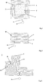
- FIG. 1 shows a schematic sectional view of a workpiece 1, which is designed as a container. Accordingly, the workpiece 1 has an inner region 2 for receiving a gaseous or liquid medium.
- the workpiece 1 is a pressure vessel in which the test medium M stored in the inner region 2 is stored under increased pressure conditions in relation to an ambient pressure.
- a test chamber 4 is introduced, which was formed by a generative manufacturing process.
- an inlet or measuring channel 5 is provided, to which a pressure sensor 6 is arranged for measuring the pressure in the test chamber 4.
- the pressure prevailing in the test chamber 4 is higher than the pressure prevailing in the inner region 2.
- the test chamber 4 is arranged corresponding contour close to a pressure-loaded contour 7 of the workpiece 1, so that early detection of cracks is possible.
- the test chamber 4 comprises a plurality of test leads having a in FIG. 1 form not shown network structure.
- FIG. 2 shows a further embodiment in which the workpiece 1 is designed as a line section. Essential features correspond to those already in FIG. 1 shown embodiment.
- the workpiece 1 of the second embodiment is designed to guide a gaseous or liquid medium in the inner region 2.
- the test space 4 is arranged, in which a higher pressure prevails compared to the inner area 2.
- the pressure in the test chamber 4 can be continuously monitored, so that cracking can be detected early by detecting a pressure drop.
- the test chamber 4 comprises one or more test lines and / or a section with a porous or partially porous inner region which has been produced by means of a generative production method, in particular a laser sintering and / or laser melting method.
- FIG. 3 shows a workpiece 1 according to another embodiment in a schematic sectional view, which is designed as an insert for an injection mold.
- the test chamber 4 is arranged near the pressure-loaded contour 7, which is acted upon in a manner not shown in detail when using the insert 1 formed as a workpiece during die casting with a spray material, such as aluminum.
- the distance of the test chamber 4 to the pressure-loaded contour 7 of the workpiece 1 is 4 mm in the exemplary embodiment illustrated.
- cooling channels 8 are introduced a cooling channel structure, which are flushed to cool the workpiece 1 during normal use with a coolant, in particular water.
- the test chamber 4 is arranged between the cooling channel structure and the pressure-loaded contour 7 so that cracks can be detected early, ideally before hot spray material comes into contact with the coolant guided in the cooling channels 8.
- the test chamber 4 is formed in sections by test lines, which optionally form a network structure or have porous or partially porous interior regions in sections.
- FIG. 4 shows a further workpiece 1 according to a possible embodiment of the invention. Shown is a schematic cross section through the workpiece 1 with test chamber 4, which has arcuate bridge structures. The bridge structures are directed with their arc portions in the direction of the pressure-loaded contour 7 and act as pressure-receiving elements in order to compensate at least partially for the pressures on the contour 7 during normal use of the workpiece 1. According to a concrete embodiment, the in FIG. 4 shown workpiece 1 designed as an insert for use in an aluminum die-casting process.
- FIG. 5 shows another embodied as a support structure workpiece 1 according to a fifth embodiment of the invention.
- This in FIG. 6 shown in a schematic sectional view of workpiece 1 is designed as a longitudinal beam having a closed test chamber 4, in which a reactive and gaseous test medium M is included under pressure. When cracking the exiting test medium M by means of the gas sensor 9 is chemically detected.
- the in FIG. 5 shown longitudinal beam has a test chamber 4, which is partially filled with sintered powdery metallic building material.
- Such test rooms can be produced by means of the generative manufacturing method in that the metallic building material is not heated above its melting temperature when irradiated.
- FIG. 6 schematically shows a plurality of test rooms 4, which have network structures formed by single-channel sections.
- the embodiments according to Figures 6b and 6e However, all the test spaces 4 shown form a sheet-like structure and are suitable to allow any cracking over the entire pressure-loaded contour 7.
- the test room 4 with the in Figures 6a, 6c, 6d and 6f shown network structures have single-channel sections 11, which are also connected to each other in the transverse direction.
- 11 regions are formed between the individual channel sections, which have oval, honeycomb, diamond-shaped or round cross-section.
- test chamber 4 Under which the test chamber 4 is arranged, it is provided to vary the density of the individual channel sections 11. In particular, it is provided to form the network structure of the test space 4 in areas of increased stress in such a way that it has a density arrangement of individual channel sections 11 in the loaded area in order to detect crack formation at an early stage.
Landscapes
- Physics & Mathematics (AREA)
- General Physics & Mathematics (AREA)
- Engineering & Computer Science (AREA)
- Aviation & Aerospace Engineering (AREA)
- Powder Metallurgy (AREA)
- Testing Of Devices, Machine Parts, Or Other Structures Thereof (AREA)
- Molds, Cores, And Manufacturing Methods Thereof (AREA)
- Investigating Strength Of Materials By Application Of Mechanical Stress (AREA)
Description
- Die Erfindung betrifft ein Werkstück, umfassend eine Vorrichtung zur Früherkennung von Rissbildungen in dem Werkstück oder in mechanisch belasteten Bauteilen wie Trägern, Spanten, und dgl., insbesondere von mit einem Innendruck belasteten medienführenden Werkstücken in Form von Spritzwerkzeugen und deren Einsätzen, Ventilen und deren Komponenten, Flüssigkeits- oder Gasbehältern oder Leitungen, Druckbehältern und Leitungen von Kraftwerken sowie Hydraulikkomponenten oder strukturbildenden Teilen oder Antriebsteilen von insbesondere Flugzeugen, Fahrzeugen oder Schiffen.
- Rissbildung von mit einem Innendruck belasteten Werkstücken kann ein ernst zu nehmendes Problem bei einer Vielzahl von unterschiedlichen industriellen Anwendungen darstellen. Daher werden typischerweise Kühlkreisläufe von Kraftwerken, welche Kühlmedien führende Leitungen aufweisen, kontinuierlich hinsichtlich Innendrücken überwacht. Ein etwaiger Defekt des Kühlkreislaufs kann frühzeitig über einen erfassten Druckabfall identifiziert werden, so dass etwaige Gegenmaßnahmen zur Bereitstellung einer ausreichenden Kühlung getroffen werden können. Im Bereich von Verbrennungsmotoren ist es üblich, Öldrucksensoren vorzusehen, die den innerhalb von Motoröl führenden Komponenten vorherrschenden Druck kontinuierlich überwachen. Ein Abfall des Öldrucks kann auf undichte Stellen, insbesondere defekte Dichtungen hinweisen.
- Es ist wünschenswert, derartige Defekte und insbesondere Rissbildungen frühzeitig zu erkennen, insbesondere in Fällen, wenn ein Austritt eines innerhalb des Werkstücks geführten Mediums mit einer Kontaminierung der Umgebung einhergehen würde oder wenn die Gefahr besteht, dass das Medium bei einem Austritt mit anderen Komponenten der Umgebung stark exotherm und explosionsartig reagieren würde.
- Im Bereich der Spritzgusstechnik sind Spritzwerkzeuge wie Spritzgussformen und Einsätze für Spritzgussformen bekannt, die unter hohem Druck mit flüssiger Schmelze befüllt bzw. umspült werden. Insbesondere beim Aluminiumdruckguss unterliegen die Spritzwerkzeuge hohen thermischen und mechanischen Belastungen. Die Einsätze reißen oftmals bei wiederholtem Gebrauch. Problematisch ist insbesondere, dass die Einsätze typischerweise zur Kühlung Kühlkanäle aufweisen, in denen meist Wasser als Kühlmedium geführt ist. Gelangt das Wasser über Risse in direkten Kontakt mit dem heißen Aluminium, so kann es zur Explosion kommen. Aus dem Stand der Technik, wie es beispielsweise in der
EP 1 547 749 A1 oderJP 2005 300 498 A JP 2013 035 204 A EP 2 045 065 A2 offenbart ist, Werkstücke für Spritzgießvorrichtungen durch ein sogenanntes generatives Aufbauverfahren herzustellen. - Ausgehend von diesem Stand der Technik ist es Aufgabe der vorliegenden Erfindung, eine Vorrichtung zur Früherkennung von Rissbildungen anzugeben, die eine zuverlässige und frühzeitige Identifizierung von Rissen ermöglicht.
- Die Aufgabe wird gelöst durch eine Vorrichtung der eingangs genannten Art mit den kennzeichnenden Merkmalen des Patentanspruches 1.
- Vorteilhafte Ausführungsformen der Erfindung sind Gegenstand der Unteransprüche.
- Als Kern der Erfindung wird es angesehen, im Bereich wenigstens einer rissgefährdeten Oberfläche wenigstens einen mit einem Prüfmedium unter Druck beaufschlagten Prüfraum anzuordnen, der durch ein generatives Herstellungsverfahren des Werkstücks oder eines Werkstückabschnitts ausgebildet ist.
- Eine Rissbildung des Werkstücks wird entweder über einen Druckabfall innerhalb des Prüfraums identifiziert, welcher über einen am Prüfraum angeschlossenen Drucksensor erfassbar ist, oder mittels eines Gassensors erfasst, der auf ein bei Rissbildung aus dem Prüfraum austretendes Prüfmedium reagierfähig ist und in der Umgebung des Prüfraums angeordnet ist.
- Als generative Herstellungsverfahren kommen insbesondere Verfahren in Betracht, bei denen das Werkstück bzw. der Werkstückabschnitt schichtweise aus durch Einwirkung von Strahlung verfestigbarem Aufbaumaterial gebildet wird. Solche üblicherweise als Lasersinter- oder Laserschmelzverfahren bezeichnete Herstellungsverfahren haben zum Vorteil, dass Bauteile auch in geringer Stückzahl wirtschaftlich hergestellt werden können. Ein derartiges generatives Herstellungsverfahren stellt die effiziente Herstellung des den Prüfraum beinhaltenden Werkstückes bzw. Werkstückabschnittes sicher.
- Es ist somit vorgesehen, das Werkstück entweder vollständig mittels dem generativen Herstellungsverfahren herzustellen oder den Werkstückabschnitt, welcher den Prüfraum beinhaltet, derartig herzustellen. Letzterer Fall bezieht sich auf die sogenannte Hybridbauweise, bei der eine Komponente des Werkstücks konventionell, beispielsweise durch Gieß- oder Fräsverfahren hergestellt wird. Auf diese Komponente wird in einem weiteren Verfahrensschritt der Werkstückabschnitt generativ aufgebaut, wobei sukzessive Schichten aus pulverförmigen und insbesondere metallischen Aufbaumaterial durch Einwirkung von Strahlung verfestigt werden. Die dazu verwendete Strahlung kann Elektronen- oder Laserstrahlung umfassen.
- Bei Rissbildung wird ein Druckabfall im Prüfraum erzeugt, der mittels des Drucksensors zuverlässig erfassbar ist. Entsprechend ist eine Früherkennung von Rissbildungen gegeben, die in einer Vielzahl von verschiedenster technischer Bereiche Anwendung finden kann. Die Früherkennung ermöglicht generell, auf die Gefahrensituation zeitnah reagieren zu können und adäquate Gegenmaßnahmen einzuleiten.
- Jedoch ist der erfindungswesentliche Gedanke nicht darauf beschränkt, eine Rissbildung mittels Erfassung eines Druckabfalls im Prüfraum zu erkennen. Vielmehr ist ebenso vorgesehen, eine Rissbildung mittels eines Gassensors zu detektieren, welcher in der Umgebung des Prüfraums angeordnet ist und auf das im Prüfraum vorgesehene Prüfmedium reagierfähig ist. Entsprechend finden bei derartigen Ausführungsformen vorzugsweise reaktive Substanzen als Prüfmedien Anwendung, die mittels geeigneter Reaktionen in Spuren nachweisbar sind. Ein Einlass- bzw. Messkanal zur Anordnung eines Drucksensors ist nicht notwendig. Vielmehr kann der mit dem Prüfmedium beaufschlagte Prüfraum geschlossen ausgebildet werden, um eine hohe mechanische Stabilität des Bauteils sicherzustellen. Eine derartige Detektion von Rissbildung eignet sich daher insbesondere für strukturbildende und/oder mechanisch belastete Bauteile.
- Es versteht sich, dass die erfindungsgemäße Vorrichtung zur Früherkennung von Rissbildungen in medienführenden Werkstücken vorteilhafterweise in Ventilen und deren Komponenten, Flüssigkeits- oder Gasbehältern, Druckbehältern und Leitungen, insbesondere von Kraftwerken sowie in Hydraulikkomponenten eingesetzt wird. Ferner ist vorgesehen strukturbildende Teile oder Antriebsteile von insbesondere Flugzeugen, Fahrzeugen oder Schiffen mit der erfindungsgemäßen Vorrichtung zur Rissbildung zu versehen.
- Erfindungsgemäß ist der Prüfraum unter einer druckbelasteten Kontur des Werkstückes angeordnet. Beispielsweise ist das Werkstück als Einsatz für eine Druckgussform ausgebildet, welche beim Druckgießen erheblichen Drücken ausgesetzt ist. Der Prüfraum dient bei diesem Ausführungsbeispiel dazu, frühzeitig zu erkennen, ob das verflüssigte Spritzmaterial während des Druckgießens in den Einsatz gelangt. In einem anderen Ausführungsbeispiel ist das Werkstück als Leitung ausgebildet, welches beispielsweise unter Druckbeaufschlagung ein gasförmiges oder flüssiges Medium führt. Der Prüfraum ist beispielsweise in der Wandung der Leitung angeordnet, um frühzeitig Risse anzuzeigen. Zudem kann durch eine derartig ausgebildete Vorrichtung ein Austritt des Gas- oder flüssigen Mediums bei Rissbildung vermieden werden, wenn der im Prüfraum vorherrschende Druck größer ist als die Drücke, die typischerweise im medienführenden Innenraum auftreten.
- Dadurch, dass der Prüfraum durch ein generatives Herstellungsverfahren gebildet ist, ist hinsichtlich der räumlichen Gestaltung des Prüfraums eine Vielzahl von unterschiedlichen Möglichkeiten gegeben, die wirtschaftlich effizient realisiert werden können. In einem Ausführungsbeispiel wird der Prüfraum durch eine oder mehrere generativ im Werkstückinnenbereich angeordnete Prüfleitung gebildet. In einem anderen Ausführungsbeispiel wird der Prüfraum durch einen porösen oder teilporösen Innenbereich des Werkstücks oder von einer durch Einzelkanalabschnitte gebildeten Netzstruktur gebildet. Selbstverständlich können auch Kombinationen vorgesehen sein, bei denen der Prüfraum abschnittsweise von Prüfleitungen, Netzstruktur und/oder porösen oder teilporösen Innenbereichen gebildet ist. Poröse oder teilporöse Bereiche des Werkstückes lassen sich durch das generative Herstellungsverfahren, insbesondere Laserschmelzverfahren, besonders einfach dadurch erzeugen, dass die entsprechenden Bereiche mit einem verminderten Energieeintrag pro Fläche bestrahlt werden, was zur Folge hat, dass das pulverartige metallische Baumaterial zumindest zum Teil nicht vollständig aufgeschmolzen wird. Nach Verfestigung der entsprechenden Schicht ist so ein poröser bzw. Teilbereich des Werkstückes gebildet.
- Die Dichte der Einzelkanalabschnitte ist vorzugsweise abhängig von einer potentiellen Rissgefährdung des sie beinhaltenden Werkstückabschnittes. So können beispielsweise Werkstückabschnitte, die besonders hohen Drücken oder mechanischen Belastungen ausgesetzt sind und/oder an exponierter Stelle lokalisiert sind, eine erhöhte Dichte von Einzelkanalabschnitten aufweisen, um eine zuverlässige Früherkennung von Rissbildungen sicherzustellen.
- Bei Spritzgussanwendungen verläuft der Prüfraum vorzugsweise konturnah zu einer formbildenden Innenfläche des Spritzgießwerkzeugs. Entsprechend verläuft der Prüfraum in unmittelbarer Nähe der mit Druck beaufschlagten Innenfläche von Spritzgussformen und deren Einsätzen. Damit wird erreicht, dass eine Erkennung von Rissen noch vor einer weitgehenden Schädigung des Spritzwerkzeuges ermöglicht ist.
- Es hat sich als vorteilhaft erwiesen, wenn der Abstand zwischen der druckbelasteten Kontur des Werkstückes, insbesondere des Spritzwerkstückes, und dem darunter verlaufenden Prüfraum im Wesentlichen 1 - 5 mm beträgt.
- Das Werkstück wird mit einer Kühlkanalstruktur versehen und der Prüfraum verläuft zumindest bereichsweise zwischen der druckbelasteten Kontur des Werkstückes und der Kühlkanalstruktur. Ein derartiges Werkstück kann insbesondere als Spritzgusswerkzeug insbesondere als Einsatz für eine Spritzgussform ausgebildet sein. Insbesondere beim Aluminiumdruckguss ist es wünschenswert, eine frühzeitige Erkennung von Rissen bereitzustellen da es beim Kontakt des heißen Aluminiums mit dem in der Kühlkanalstruktur geführtem Wasser zu Explosionen kommen kann. Der zwischen der Kühlkanalstruktur und der druckbelasteten Außenkontur des Einsatzes liegende Prüfraum ermöglicht eine derartige frühzeitige Erkennung. Zudem kann einem weiteren Eindringen der Schmelze in das Werkstück dadurch entgegengewirkt werden, wenn das Prüfmedium im Prüfraum unter Drücke geführt wird, die größer sind als diejenigen Drücke, mit denen das Druckgussverfahren durchgeführt wird.
- In diesem Zusammenhang hat es sich als vorteilhaft erwiesen, wenn das im Prüfraum angeordnete Prüfmedium mit einem in Verbindung mit dem als Spritzwerkzeug ausgebildeten Werkstück verwendeten Spritzmaterial nicht reagierfähig ist. Im Falle des Aluminiumdruckgusses kann beispielsweise Pressluft als Druckmedium verwendet werden. Jedoch ist es auch in Ausführungsformen die Flüssigkeits- oder Gasbehälter, Leitungen, Ventile oder dergleichen betreffen sinnvoll, Druckmedien zu verwenden, die reaktionsträge sind, insbesondere wenn bei Rissbildung ein unmittelbarer Kontakt mit einem reaktionsfreudigen Medium zu befürchten ist.
- In Weiterbildung der Erfindung ist vorgesehen, den Prüfraum zumindest in einem hochbelasteten Konturbereich von Druckaufnahmeelementen zu durchsetzen.
- Diese Druckaufnahmeelemente sind beispielsweise von Brückenstrukturen gebildet, die mit ihren Bogenbereichen zur druckbelasteten Kontur hin gerichtet sind. Derartige Brückenstrukturen lassen sich während des generativen Herstellungsverfahrens einfach in das Werkstück einbringen. Die Druckaufnahmeelemente können Druckschwankungen, die lokal auftreten, zumindest teilweise kompensieren, so dass der Prüfraum zusätzlich zur Früherkennung auch dafür genutzt wird, einer etwaigen Rissbildung aktiv entgegenzuwirken.
- Der Prüfraum ist vorzugsweise mit zumindest teilweise unverfestigtem oder lediglich gesintertem pulverartigen metallischen Baumaterial ausgefüllt. Die entsprechenden Bereiche werden somit während des generativen Herstellungsprozesses nicht über eine, die oberhalb der Schmelztemperatur des metallischen Baumaterials liegenden Temperatur erhitzt.
- An dem Prüfraum ist vorzugsweise wenigstens ein Einlass- oder Messkanal angeschlossen, der Messkanal kann beispielsweise dazu ausgeführt sein, ein als Sonde ausgeführtes Druckmessgerät aufzunehmen, um die innerhalb des Prüfraums vorliegenden Druckverhältnisse zu erfassen.
- Bevorzugt wird Druckluft als Prüfmedium im Prüfraum verwendet, insbesondere in Anwendungen, in denen eine Reaktion des Mediums mit Sauerstoff aus der nicht zu befürchten ist.
- Im Folgenden wird die Erfindung anhand von Ausführungsbeispielen, die in den Zeichnungsfiguren gezeigt sind, näher beschrieben. Dabei zeigen:
- Fig. 1
- ein als Behältnis ausgebildetes Werkstück gemäß einem ersten Ausführungsbeispiel der Erfindung;
- Fig. 2
- ein als Leitungsabschnitt ausgeführtes Werkstück gemäß einem zweiten Ausführungsbeispiel;
- Fig. 3
- ein als Einsatz einer Spritzgussform ausgebildetes Werkstück gemäß einem dritten Ausführungsbeispiel;
- Fig. 4
- ein Werkstück gemäß einem vierten Ausführungsbeispiel, deren Prüfraum Brückenstrukturen mit Bogenbereichen aufweist, die als Druckaufnahmeelemente fungieren;
- Fig. 5
- ein als Längsträger ausgebildetes Werkstück gemäß einem sechsten Ausführungsbeispiel mit teilweise gesintertem Prüfraum;
- Fig. 6
- exemplarische Darstellungen von Prüfräumen, die eine durch Einzelkanalabschnitte gebildete Netzstruktur aufweisen.
- Einander entsprechende Teile sind allen Figuren mit den gleichen Bezugszeichen versehen.
-
Figur 1 zeigt in einer schematischen Schnittdarstellung ein Werkstück 1, welches als Behältnis ausgeführt ist. Entsprechend weist das Werkstück 1 einen Innenbereich 2 zur Aufnahme eines gasförmigen- oder flüssigen Mediums auf. - In einem Ausführungsbeispiel ist das Werkstück 1 ein Druckbehälter, bei dem das im Innenbereich 2 gelagerte Prüfmedium M unter gegenüber eines Umgebungsdrucks erhöhten Druckverhältnissen bevorratet ist. In eine Wandung 3 des Werkstückes 1 ist ein Prüfraum 4 eingebracht, der durch ein generatives Herstellungsverfahren gebildet wurde. Am Prüfraum 4 ist ein Einlass- bzw. Messkanal 5 vorgesehen, an dem zur Messung des Druckes im Prüfraum 4 ein Drucksensor 6 angeordnet ist. Der im Prüfraum 4 vorherrschende Druck liegt über den im Innenbereich 2 vorherrschenden Drücken. Somit verursacht eine Rissbildung in dem den Innenbereich 2 zugewandten Abschnitt der Wandung 3 einen raschen Druckabfall, der mittels des Drucksensor 6 erfassbar ist.
- Der Prüfraum 4 ist entsprechend konturnah an einer druckbelasteten Kontur 7 des Werkstückes 1 angeordnet, so dass eine frühzeitige Erkennung von Rissen ermöglicht ist. Der Prüfraum 4 umfasst eine Vielzahl von Prüfleitungen, die eine in
Figur 1 nicht näher dargestellte Netzstruktur bilden. -
Figur 2 zeigt ein weiteres Ausführungsbeispiel, bei dem das Werkstück 1 als Leitungsabschnitt ausgeführt ist. Wesentliche Merkmale entsprechen hierbei dem bereits inFigur 1 gezeigten Ausführungsbeispiel. Das Werkstück 1 des zweiten Ausführungsbeispiels ist zur Führung eines gasförmigen oder flüssigen Mediums im Innenbereich 2 ausgebildet. Zwischen einer Umgebung des Leitungsabschnitts und dem Innenbereich 2 ist der Prüfraum 4 angeordnet, in dem ein im Vergleich zum Innenbereich 2 erhöhter Druck vorherrscht. Über den Einlass- bzw. Messkanal 5 und dem Drucksensor 6 ist der Druck im Prüfraum 4 kontinuierlich überwachbar, so dass eine Rissbildung durch Detektion eines Druckabfalls frühzeitig erkannt werden kann. - Gemäß alternativen Ausführungsbeispielen umfasst der Prüfraum 4 ein oder mehrere Prüfleitungen und/oder einen Abschnitt mit porösen oder teilporösen Innenbereich, der mittels eines generativen Herstellungsverfahrens, insbesondere eines Lasersinter- und/oder Laserschmelzverfahrens hergestellt wurde.
-
Figur 3 zeigt ein Werkstück 1 gemäß einem weiteren Ausführungsbeispiel in einer schematischen Schnittdarstellung, das als Einsatz für eine Spritzgussform ausgebildet ist. Der Prüfraum 4 ist nahe der druckbelasteten Kontur 7 angeordnet, welche in nicht näher dargestellter Art und Weise bei Verwendung des als Einsatz ausgebildeten Werkstückes 1 beim Druckgießen mit einem Spritzmaterial, beispielsweise Aluminium beaufschlagt wird. Der Abstand des Prüfraums 4 zur druckbelasteten Kontur 7 des Werkstückes 1 beträgt in dem exemplarisch dargestellten Ausführungsbeispiel 4 mm. - Es versteht sich, dass in Abhängigkeit von den verwendeten Spritzmaterialien und den Dimensionen der herzustellenden Formteile auch andere Abstände bevorzugt sind, wie beispielsweise Abstände von wenigen Zentimetern bis hin zu wenigen Millimetern.
- Im Werkstück 1 sind Kühlkanäle 8 einer Kühlkanalstruktur eingebracht, die zur Kühlung des Werkstückes 1 beim bestimmungsgemäßen Gebrauch mit einem Kühlmittel, insbesondere Wasser durchspült sind. Der Prüfraum 4 ist zwischen der Kühlkanalstruktur und der druckbelasteten Kontur 7 angeordnet, so dass Risse frühzeitig erkannt werden können, im Idealfall bevor heißes Spritzmaterial in Kontakt mit dem in den Kühlkanälen 8 geführtem Kühlmittel kommen. Entsprechend den bereits beschriebenen Ausführungsbeispielen ist der Prüfraum 4 abschnittsweise von Prüfleitungen gebildet, die gegebenenfalls eine Netzstruktur bilden oder abschnittsweise poröse oder teilporöse Innenbereiche aufweisen.
-
Figur 4 zeigt ein weiteres Werkstück 1 gemäß einem möglichen Ausführungsbeispiel der Erfindung. Gezeigt ist ein schematischer Querschnitt durch das Werkstück 1 mit Prüfraum 4, der bogenförmige Brückenstrukturen aufweist. Die Brückenstrukturen sind mit ihren Bogenbereichen in Richtung der druckbelasteten Kontur 7 gerichtet und fungieren als Druckaufnahmeelemente, um die beim bestimmungsgemäßen Gebrauch des Werkstücks 1 auf der Kontur 7 lastenden Drücke zumindest teilweise zu kompensieren. Gemäß einem konkreten Ausführungsbeispiel ist das inFigur 4 gezeigte Werkstück 1 als Einsatz zur Verwendung in einem Aluminiumdruckgussverfahren ausgebildet. -
Figur 5 zeigt ein weiteres als Trägerkonstruktion ausgeführtes Werkstück 1 gemäß einem fünften Ausführungsbeispiel der Erfindung. Das inFigur 6 in einer schematischen Schnittdarstellung gezeigte Werkstück 1 ist als Längsträger ausgeführt, der einen geschlossenen Prüfraum 4 aufweist, in dem ein reaktionsfähiges und gasförmiges Prüfmedium M unter Druck eingeschlossen ist. Bei Rissbildung ist das austretende Prüfmedium M mittels des Gassensors 9 chemisch nachweisbar. Der inFigur 5 gezeigte Längsträger weist einen Prüfraum 4 auf, der teilweise mit gesintertem pulverartigem metallischen Baumaterial ausgefüllt ist. Derartige Prüfräume sind mittels des generativen Herstellungsverfahrens dadurch herstellbar, dass das metallische Baumaterial bei Bestrahlung nicht über ihre Schmelztemperatur erhitzt wird. -
Figur 6 zeigt schematisch mehrere Prüfräume 4, die durch Einzelkanalabschnitte gebildete Netzstrukturen aufweisen. Die Ausführungsbeispiele gemäßFiguren 6b und 6e zeigen nicht miteinander quer verbundene Einzelkanalabschnitte 11. Alle gezeigten Prüfräume 4 bilden jedoch eine flächenartige Struktur und sind dazu geeignet, eine etwaige Rissbildung über die gesamte druckbelastete Kontur 7 zu ermöglichen. - Der Prüfraum 4 mit den in
Figuren 6a, 6c, 6d und 6f gezeigten Netzstrukturen weisen Einzelkanalabschnitte 11 auf, die auch in Querrichtung miteinander verbunden sind. Dabei werden zwischen den Einzelkanalabschnitten 11 Bereiche gebildet, die oval, wabenförmigen, rautenförmigen oder runden Querschnitt aufweisen. - Je nach räumlicher Ausdehnung der druckbelasteten Kontur 7, unter der der Prüfraum 4 angeordnet ist, ist vorgesehen, die Dichte der Einzelkanalabschnitte 11 zu variieren. Insbesondere ist vorgesehen, in Bereichen erhöhter Belastung die Netzstruktur des Prüfraums 4 derart auszubilden, dass dieser im belasteten Bereich eine Dichteanordnung von Einzelkanalabschnitten 11 aufweist, um Rissbildungen frühzeitig erkennen zu können.
- Bei mechanisch belasteten oder strukturbildenden Werkstücken 1 ist vorgesehen, die Dichte der die Netzstruktur bildende Einzelkanalabschnitte 11 in Abhängigkeit einer erfassten oder insbesondere mittels Simulation ermittelten mechanischen Belastung zu variieren.
-
- 1
- Werkstück
- 2
- Innenbereich
- 3
- Wandung
- 4
- Prüfraum
- 5
- Einlasskanal
- 6
- Drucksensor
- 7
- Kontur
- 8
- Kühlkanal
- 9
- Gassensor
- 10
- Bereich
- 11
- Einzelkanalabschnitt
- M
- Prüfmedium
Claims (13)
- Werkstück (1), umfassend eine Vorrichtung zur Früherkennung von Rissbildungen in dem Werkstück (1)
dadurch gekennzeichnet, dass
im Bereich wenigstens einer rissgefährdeten Oberfläche des Werkstücks (1) wenigstens ein mit einem Prüfmedium unter Druck beaufschlagter Prüfraum (4) angeordnet ist, der durch ein generatives Herstellungsverfahren des Werkstückes (1) oder eines Werkstückabschnittes ausgebildet ist, wobei am Prüfraum (4) entweder ein Drucksensor (6) zur Ermittlung eines aus einer Rissbildung des Werkstückes (1) resultierenden Druckabfalls angeschlossen ist oder in der Umgebung des Prüfraums (4) ein Gassensor (9) angeordnet ist, der auf ein bei Rissbildung aus dem Prüfraum (4) austretendes Prüfmedium reagierfähig ist, wobei der Prüfraum (4) unter einer druckbelasteten Kontur (7) des Werkstückes (1) angeordnet ist, wobei das Werkstück (1) mit einer Kühlkanalstruktur (8) versehen ist und der Prüfraum (4) zumindest bereichsweise zwischen der druckbelasteten Kontur (7) des Werkstückes (1) und der Kühlkanalstruktur (8) verläuft. - Werkstück nach Anspruch 1,
dadurch gekennzeichnet, dass
der Prüfraum (4) durch eine oder mehrere generativ im Werkstückinnenbereich angeordnete Prüfleitungen gebildet wird. - Werkstück nach einem der vorhergehenden Ansprüche,
dadurch gekennzeichnet, dass
der Prüfraum (4) durch ein bei einem generativen Herstellungsverfahren unter Verwendung von pulverartigem metallischem und zumindest teilweise nicht vollständig aufgeschlossenen Baumaterial und damit porösen oder teilporösen Innenbereich des Werkstückes (1) gebildet wird. - Werkstück nach einem der vorhergehenden Ansprüche,
dadurch gekennzeichnet, dass
der Prüfraum (4) eine durch Einzelkanalabschnitte gebildete Netzstruktur aufweist. - Werkstück nach Anspruch 4,
dadurch gekennzeichnet, dass
die Dichte der Einzelkanalabschnitte abhängig von einer potentiellen Rissgefährdung des sie beinhaltenden Werkstückabschnittes ist. - Werkstück nach einem der vorangehenden Ansprüche,
dadurch gekennzeichnet, dass
der Prüfraum (4) konturnah zu einer formbildenden Innenfläche des Spritzgießwerkzeuges verläuft. - Werkstück nach einem der vorangehenden Ansprüche,
dadurch gekennzeichnet, dass
der Abstand zwischen der druckbelasteten Kontur (7) des Werkstückes (1) und dem darunter verlaufenden Prüfraum (4) 1 - 5 mm beträgt. - Werkstück nach einem der vorhergehenden Ansprüche,
dadurch gekennzeichnet, dass
das im Prüfraum (4) angeordnete Prüfmedium mit einem in Verbindung mit dem als Spritzwerkzeug ausgebildeten Werkstück (1) verwendeten Spritzmaterial nicht reagierfähig ist. - Werkstück nach einem der vorhergehenden Ansprüche,
dadurch gekennzeichnet, dass
der Prüfraum (4) zumindest in einem hochbelasteten Konturbereich von Druckaufnahmeelementen durchsetzt ist. - Werkstück nach Anspruch 9,
dadurch gekennzeichnet, dass
der Prüfraum (4) generativ eingebaute, mit ihren Bogenbereichen zur druckbelasteten Kontur (7) hin gerichtete Brückenstrukturen als Druckaufnahmeelemente aufweist. - Werkstück nach einem der vorhergehenden Ansprüche,
dadurch gekennzeichnet, dass
der Prüfraum (4) mit zumindest teilweise unverfestigtem oder lediglich gesintertem pulverartigen metallischen Baumaterial ausgefüllt ist. - Werkstück nach einem der vorhergehenden Ansprüche,
dadurch gekennzeichnet, dass
an dem Prüfraum (4) wenigstens ein Einlass- oder Messkanal (5) angeschlossen ist. - Werkstück nach einem der vorhergehenden Ansprüche,
gekennzeichnet durch
Druckluft als Prüfmedium im Prüfraum (4).
Priority Applications (2)
| Application Number | Priority Date | Filing Date | Title |
|---|---|---|---|
| SI201431212T SI2853875T1 (sl) | 2013-09-30 | 2014-09-15 | Obdelovanec, obsegajoč pripravo za zgodnjo zaznavo tvorbe razpok v obdelovancu |
| PL14003190T PL2853875T3 (pl) | 2013-09-30 | 2014-09-15 | Przedmiot obrabiany, obejmujący urządzenie do wczesnego wykrywania powstawania pęknięć w przedmiocie obrabianym |
Applications Claiming Priority (1)
| Application Number | Priority Date | Filing Date | Title |
|---|---|---|---|
| DE102013016166.5A DE102013016166B4 (de) | 2013-09-30 | 2013-09-30 | Vorrichtung zur Früherkennung von Rissbildungen in medienführenden Werkstücken |
Publications (2)
| Publication Number | Publication Date |
|---|---|
| EP2853875A1 EP2853875A1 (de) | 2015-04-01 |
| EP2853875B1 true EP2853875B1 (de) | 2019-02-20 |
Family
ID=51542133
Family Applications (1)
| Application Number | Title | Priority Date | Filing Date |
|---|---|---|---|
| EP14003190.7A Not-in-force EP2853875B1 (de) | 2013-09-30 | 2014-09-15 | Werkstück, umfassend eine Vorrichtung zur Früherkennung von Rissbildungen in dem Werkstück |
Country Status (9)
| Country | Link |
|---|---|
| US (1) | US9568393B2 (de) |
| EP (1) | EP2853875B1 (de) |
| DE (1) | DE102013016166B4 (de) |
| ES (1) | ES2719784T3 (de) |
| HU (1) | HUE043102T2 (de) |
| PL (1) | PL2853875T3 (de) |
| PT (1) | PT2853875T (de) |
| SI (1) | SI2853875T1 (de) |
| TR (1) | TR201906459T4 (de) |
Families Citing this family (1)
| Publication number | Priority date | Publication date | Assignee | Title |
|---|---|---|---|---|
| CN107219168B (zh) * | 2017-08-02 | 2024-03-29 | 贵州工程应用技术学院 | 一种预损伤智能损伤探测器 |
Citations (1)
| Publication number | Priority date | Publication date | Assignee | Title |
|---|---|---|---|---|
| EP2801809A1 (de) * | 2013-05-06 | 2014-11-12 | Vrije Universiteit Brussel | Strukturelle Integritätsüberwachung mit Hohlraumstruktur |
Family Cites Families (22)
| Publication number | Priority date | Publication date | Assignee | Title |
|---|---|---|---|---|
| US1052392A (en) * | 1912-01-08 | 1913-02-04 | Harry Van Dyken | Means for indicating fractures in crank-pins and the like. |
| US2185315A (en) * | 1939-01-09 | 1940-01-02 | Rogatchoff Theodore | Means for detecting cracks in crankpins and the like |
| US4031751A (en) * | 1976-09-22 | 1977-06-28 | Haddad And Brooks, Inc. | Closed system for testing the condition of well bore formations |
| DE3049628C2 (de) * | 1980-12-31 | 1982-10-21 | Basf Ag, 6700 Ludwigshafen | Verfahren zur Überwachung des Entstehens und Fortschreitens von Rissen in Maschinenteilen und Bauteilen sowie eine Vorrichtung zur Durchführung des Verfahrens |
| US4447388A (en) * | 1981-11-30 | 1984-05-08 | The United States Of America As Represented By The United States Department Of Energy | Bolt failure detection |
| JPH09254188A (ja) * | 1996-03-22 | 1997-09-30 | Toshiba Mach Co Ltd | コネクタ成形用金型のコネクタピン折損検出装置 |
| DE19740502A1 (de) * | 1997-09-15 | 1999-03-18 | Fraunhofer Ges Forschung | Verfahren zur Herstellung von Bauteilen mit einem oberflächennahen Durchfluß- und Verteilungssystem für Flüssigkeiten und/oder Gase |
| US6196056B1 (en) * | 1998-04-15 | 2001-03-06 | Vacuum Instrument Corp. | System for determining integrity of a gas-sealed compartment |
| US7186331B2 (en) * | 2001-03-06 | 2007-03-06 | Sasol Technology (Pty) Limited | Monitoring unit for monitoring the condition of a semi-permeable membrane |
| US6729797B2 (en) * | 2001-08-15 | 2004-05-04 | Delaware Capital Formation, Inc. | Testable sump apparatus |
| US7500489B2 (en) * | 2002-08-23 | 2009-03-10 | Ameron International Corporation | Contained pipeline system with brine filled interstitial space and method for detecting leakage in same |
| EP1547749A1 (de) * | 2003-12-19 | 2005-06-29 | Behr France S.A.R.L. | Vorrichtung und Verfahren zur Überwachung des Brechens von Einsätzen in Giessformen |
| JP2005300498A (ja) * | 2004-04-16 | 2005-10-27 | Gundai Kk | 検査品の液体洩れ検査方法及び検査品の液体洩れ検査装置 |
| DE102005050118B4 (de) * | 2005-10-18 | 2009-04-09 | Werkzeugbau Siegfried Hofmann Gmbh | Anordnung zur Temperierung eines metallischen Körpers sowie Verwendung derselben |
| FI20065411L (fi) * | 2006-06-16 | 2007-12-17 | Aker Mtw Werft Gmbh | Menetelmä ja järjestely säiliön vuotojen valvomiseksi ja tunnistamiseksi |
| US20080081000A1 (en) * | 2006-09-29 | 2008-04-03 | Macleod John | Integrity testing of vials for test sensors |
| US7559250B2 (en) * | 2007-09-27 | 2009-07-14 | Caterpillar Inc. | Frame crack detection method |
| DE102007047617B3 (de) * | 2007-10-04 | 2009-04-30 | Werkzeugbau Siegfried Hofmann Gmbh | Spritzgießform zum Einsatz in einer Spritzgießvorrichtung |
| US9316562B2 (en) * | 2008-04-18 | 2016-04-19 | Airbus Operations Gmbh | System and method for monitoring the state of structural components |
| DE102009027807A1 (de) * | 2009-07-17 | 2011-03-10 | Airbus Operations Gmbh | Detektionsverfahren und Detektionsvorrichtung zum Detektieren von Kernschäden und Ablösungen in Sandwichstrukturen |
| JP5758735B2 (ja) * | 2011-08-08 | 2015-08-05 | 本田技研工業株式会社 | 金型 |
| CN103032678B (zh) * | 2011-09-30 | 2015-07-22 | 国际商业机器公司 | 用于监视流体传输管道的状态的方法、装置和系统 |
-
2013
- 2013-09-30 DE DE102013016166.5A patent/DE102013016166B4/de not_active Expired - Fee Related
-
2014
- 2014-09-15 EP EP14003190.7A patent/EP2853875B1/de not_active Not-in-force
- 2014-09-15 HU HUE14003190A patent/HUE043102T2/hu unknown
- 2014-09-15 TR TR2019/06459T patent/TR201906459T4/tr unknown
- 2014-09-15 PT PT14003190T patent/PT2853875T/pt unknown
- 2014-09-15 SI SI201431212T patent/SI2853875T1/sl unknown
- 2014-09-15 ES ES14003190T patent/ES2719784T3/es active Active
- 2014-09-15 PL PL14003190T patent/PL2853875T3/pl unknown
- 2014-09-26 US US14/497,583 patent/US9568393B2/en not_active Expired - Fee Related
Patent Citations (1)
| Publication number | Priority date | Publication date | Assignee | Title |
|---|---|---|---|---|
| EP2801809A1 (de) * | 2013-05-06 | 2014-11-12 | Vrije Universiteit Brussel | Strukturelle Integritätsüberwachung mit Hohlraumstruktur |
Also Published As
| Publication number | Publication date |
|---|---|
| US20150090045A1 (en) | 2015-04-02 |
| DE102013016166B4 (de) | 2015-11-19 |
| DE102013016166A1 (de) | 2015-04-02 |
| US9568393B2 (en) | 2017-02-14 |
| TR201906459T4 (tr) | 2019-05-21 |
| ES2719784T3 (es) | 2019-07-16 |
| HUE043102T2 (hu) | 2019-08-28 |
| PT2853875T (pt) | 2019-05-09 |
| PL2853875T3 (pl) | 2019-08-30 |
| SI2853875T1 (sl) | 2019-06-28 |
| EP2853875A1 (de) | 2015-04-01 |
Similar Documents
| Publication | Publication Date | Title |
|---|---|---|
| EP3555584A1 (de) | Verfahren zum herstellen eines drucksensormesselements sowie damit erhältliches drucksensormesselement | |
| DE102008025869A1 (de) | Messsonde und Verfahren zur Herstellung einer Messsonde | |
| EP3349928B1 (de) | Verfahren und einrichtung zur additiven herstellung | |
| EP2842608A2 (de) | Druckentlastungsvorrichtung für ein explosionsgeschütztes Gehäuse und Verfahren zu deren Herstellung | |
| DE102007057450A1 (de) | Verfahren und Vorrichtung zur Herstellung eines dreidimensionalen Gegenstandes aus einem verfestigbaren Material | |
| DE102007056451A1 (de) | Verfahren zur Reparatur eines Gasturbinenbauteils | |
| DE102012024051B4 (de) | Temperierbares Werkzeug zur Formgebung von Werkstücken | |
| DE102016201836A1 (de) | Vorrichtung für eine Anlage zur additiven Herstellung eines Bauteils | |
| DE102014214939A1 (de) | Kamerabasierte Rauheitsbestimmung für generativ hergestellte Bauteile | |
| DE102016204075A1 (de) | Druckbehältersystem sowie Verfahren zum Druckentlasten eines Druckbehälters | |
| DE112019005383T5 (de) | Thermisch verbesserter Auslasskanal-Liner | |
| WO2018087137A1 (de) | Verfahren für die additive herstellung mit kennzeichnung einer bauplattform durch referenzpunkte | |
| WO1992016787A1 (de) | Doppelwandiger druckbehälter und verfahren zu seiner herstellung | |
| DE102013016166B4 (de) | Vorrichtung zur Früherkennung von Rissbildungen in medienführenden Werkstücken | |
| WO2007101743A1 (de) | Verfahren zur herstellung einer turbinen- oder verdichterkomponente sowie turbinen- oder verdichterkomponente | |
| DE2636743C2 (de) | Druckbehälter | |
| EP4197736B1 (de) | Formwerkzeug zur herstellung eines partikelschaumformteils | |
| DE10137594B4 (de) | Dichtverbindung mit höhenprofilierter Dichtfläche und Verfahren zu ihrer Herstellung | |
| EP2658059B1 (de) | Druckausgleichsystem für Kryostat | |
| EP2774670B1 (de) | System umfassend einen Reaktor und eine Unterdruckerzeugungseinrichtung | |
| EP3953100B1 (de) | Vorrichtung und verfahren zum beschichten von werkstücken | |
| DE102008000044A1 (de) | Werkzeugkühlsystem | |
| EP3453933B1 (de) | Ventilkörperelement mit eingebetteten sensoren | |
| DE102020007162A1 (de) | Verfahren zum Herstellen eines Gussbautelis | |
| DE3821304A1 (de) | Explosionskammer zur werkstoffbearbeitung durch explosionsverfahren |
Legal Events
| Date | Code | Title | Description |
|---|---|---|---|
| PUAI | Public reference made under article 153(3) epc to a published international application that has entered the european phase |
Free format text: ORIGINAL CODE: 0009012 |
|
| 17P | Request for examination filed |
Effective date: 20140915 |
|
| AK | Designated contracting states |
Kind code of ref document: A1 Designated state(s): AL AT BE BG CH CY CZ DE DK EE ES FI FR GB GR HR HU IE IS IT LI LT LU LV MC MK MT NL NO PL PT RO RS SE SI SK SM TR |
|
| AX | Request for extension of the european patent |
Extension state: BA ME |
|
| R17P | Request for examination filed (corrected) |
Effective date: 20150729 |
|
| RBV | Designated contracting states (corrected) |
Designated state(s): AL AT BE BG CH CY CZ DE DK EE ES FI FR GB GR HR HU IE IS IT LI LT LU LV MC MK MT NL NO PL PT RO RS SE SI SK SM TR |
|
| STAA | Information on the status of an ep patent application or granted ep patent |
Free format text: STATUS: EXAMINATION IS IN PROGRESS |
|
| 17Q | First examination report despatched |
Effective date: 20170725 |
|
| REG | Reference to a national code |
Ref country code: DE Ref legal event code: R079 Ref document number: 502014010822 Country of ref document: DE Free format text: PREVIOUS MAIN CLASS: G01M0003040000 Ipc: G01M0005000000 |
|
| GRAP | Despatch of communication of intention to grant a patent |
Free format text: ORIGINAL CODE: EPIDOSNIGR1 |
|
| STAA | Information on the status of an ep patent application or granted ep patent |
Free format text: STATUS: GRANT OF PATENT IS INTENDED |
|
| RIC1 | Information provided on ipc code assigned before grant |
Ipc: G01M 5/00 20060101AFI20180514BHEP Ipc: F28D 21/00 20060101ALI20180514BHEP Ipc: G01M 3/32 20060101ALI20180514BHEP Ipc: G01N 19/08 20060101ALI20180514BHEP |
|
| INTG | Intention to grant announced |
Effective date: 20180615 |
|
| GRAJ | Information related to disapproval of communication of intention to grant by the applicant or resumption of examination proceedings by the epo deleted |
Free format text: ORIGINAL CODE: EPIDOSDIGR1 |
|
| STAA | Information on the status of an ep patent application or granted ep patent |
Free format text: STATUS: EXAMINATION IS IN PROGRESS |
|
| INTC | Intention to grant announced (deleted) | ||
| GRAP | Despatch of communication of intention to grant a patent |
Free format text: ORIGINAL CODE: EPIDOSNIGR1 |
|
| STAA | Information on the status of an ep patent application or granted ep patent |
Free format text: STATUS: GRANT OF PATENT IS INTENDED |
|
| INTG | Intention to grant announced |
Effective date: 20180829 |
|
| GRAS | Grant fee paid |
Free format text: ORIGINAL CODE: EPIDOSNIGR3 |
|
| GRAA | (expected) grant |
Free format text: ORIGINAL CODE: 0009210 |
|
| STAA | Information on the status of an ep patent application or granted ep patent |
Free format text: STATUS: THE PATENT HAS BEEN GRANTED |
|
| AK | Designated contracting states |
Kind code of ref document: B1 Designated state(s): AL AT BE BG CH CY CZ DE DK EE ES FI FR GB GR HR HU IE IS IT LI LT LU LV MC MK MT NL NO PL PT RO RS SE SI SK SM TR |
|
| REG | Reference to a national code |
Ref country code: GB Ref legal event code: FG4D Free format text: NOT ENGLISH |
|
| REG | Reference to a national code |
Ref country code: CH Ref legal event code: EP |
|
| REG | Reference to a national code |
Ref country code: DE Ref legal event code: R096 Ref document number: 502014010822 Country of ref document: DE |
|
| REG | Reference to a national code |
Ref country code: AT Ref legal event code: REF Ref document number: 1098828 Country of ref document: AT Kind code of ref document: T Effective date: 20190315 |
|
| REG | Reference to a national code |
Ref country code: IE Ref legal event code: FG4D Free format text: LANGUAGE OF EP DOCUMENT: GERMAN |
|
| REG | Reference to a national code |
Ref country code: PT Ref legal event code: SC4A Ref document number: 2853875 Country of ref document: PT Date of ref document: 20190509 Kind code of ref document: T Free format text: AVAILABILITY OF NATIONAL TRANSLATION Effective date: 20190409 |
|
| REG | Reference to a national code |
Ref country code: RO Ref legal event code: EPE |
|
| REG | Reference to a national code |
Ref country code: NL Ref legal event code: MP Effective date: 20190220 |
|
| REG | Reference to a national code |
Ref country code: LT Ref legal event code: MG4D |
|
| REG | Reference to a national code |
Ref country code: ES Ref legal event code: FG2A Ref document number: 2719784 Country of ref document: ES Kind code of ref document: T3 Effective date: 20190716 |
|
| PG25 | Lapsed in a contracting state [announced via postgrant information from national office to epo] |
Ref country code: NL Free format text: LAPSE BECAUSE OF FAILURE TO SUBMIT A TRANSLATION OF THE DESCRIPTION OR TO PAY THE FEE WITHIN THE PRESCRIBED TIME-LIMIT Effective date: 20190220 Ref country code: SE Free format text: LAPSE BECAUSE OF FAILURE TO SUBMIT A TRANSLATION OF THE DESCRIPTION OR TO PAY THE FEE WITHIN THE PRESCRIBED TIME-LIMIT Effective date: 20190220 Ref country code: FI Free format text: LAPSE BECAUSE OF FAILURE TO SUBMIT A TRANSLATION OF THE DESCRIPTION OR TO PAY THE FEE WITHIN THE PRESCRIBED TIME-LIMIT Effective date: 20190220 Ref country code: NO Free format text: LAPSE BECAUSE OF FAILURE TO SUBMIT A TRANSLATION OF THE DESCRIPTION OR TO PAY THE FEE WITHIN THE PRESCRIBED TIME-LIMIT Effective date: 20190520 Ref country code: LT Free format text: LAPSE BECAUSE OF FAILURE TO SUBMIT A TRANSLATION OF THE DESCRIPTION OR TO PAY THE FEE WITHIN THE PRESCRIBED TIME-LIMIT Effective date: 20190220 |
|
| REG | Reference to a national code |
Ref country code: HU Ref legal event code: AG4A Ref document number: E043102 Country of ref document: HU |
|
| PG25 | Lapsed in a contracting state [announced via postgrant information from national office to epo] |
Ref country code: IS Free format text: LAPSE BECAUSE OF FAILURE TO SUBMIT A TRANSLATION OF THE DESCRIPTION OR TO PAY THE FEE WITHIN THE PRESCRIBED TIME-LIMIT Effective date: 20190620 Ref country code: GR Free format text: LAPSE BECAUSE OF FAILURE TO SUBMIT A TRANSLATION OF THE DESCRIPTION OR TO PAY THE FEE WITHIN THE PRESCRIBED TIME-LIMIT Effective date: 20190521 Ref country code: HR Free format text: LAPSE BECAUSE OF FAILURE TO SUBMIT A TRANSLATION OF THE DESCRIPTION OR TO PAY THE FEE WITHIN THE PRESCRIBED TIME-LIMIT Effective date: 20190220 Ref country code: LV Free format text: LAPSE BECAUSE OF FAILURE TO SUBMIT A TRANSLATION OF THE DESCRIPTION OR TO PAY THE FEE WITHIN THE PRESCRIBED TIME-LIMIT Effective date: 20190220 Ref country code: RS Free format text: LAPSE BECAUSE OF FAILURE TO SUBMIT A TRANSLATION OF THE DESCRIPTION OR TO PAY THE FEE WITHIN THE PRESCRIBED TIME-LIMIT Effective date: 20190220 Ref country code: BG Free format text: LAPSE BECAUSE OF FAILURE TO SUBMIT A TRANSLATION OF THE DESCRIPTION OR TO PAY THE FEE WITHIN THE PRESCRIBED TIME-LIMIT Effective date: 20190520 |
|
| PG25 | Lapsed in a contracting state [announced via postgrant information from national office to epo] |
Ref country code: DK Free format text: LAPSE BECAUSE OF FAILURE TO SUBMIT A TRANSLATION OF THE DESCRIPTION OR TO PAY THE FEE WITHIN THE PRESCRIBED TIME-LIMIT Effective date: 20190220 Ref country code: EE Free format text: LAPSE BECAUSE OF FAILURE TO SUBMIT A TRANSLATION OF THE DESCRIPTION OR TO PAY THE FEE WITHIN THE PRESCRIBED TIME-LIMIT Effective date: 20190220 Ref country code: SK Free format text: LAPSE BECAUSE OF FAILURE TO SUBMIT A TRANSLATION OF THE DESCRIPTION OR TO PAY THE FEE WITHIN THE PRESCRIBED TIME-LIMIT Effective date: 20190220 Ref country code: AL Free format text: LAPSE BECAUSE OF FAILURE TO SUBMIT A TRANSLATION OF THE DESCRIPTION OR TO PAY THE FEE WITHIN THE PRESCRIBED TIME-LIMIT Effective date: 20190220 |
|
| PGFP | Annual fee paid to national office [announced via postgrant information from national office to epo] |
Ref country code: TR Payment date: 20190912 Year of fee payment: 6 Ref country code: SI Payment date: 20190904 Year of fee payment: 6 Ref country code: CZ Payment date: 20190903 Year of fee payment: 6 Ref country code: RO Payment date: 20190912 Year of fee payment: 6 Ref country code: PT Payment date: 20190906 Year of fee payment: 6 |
|
| REG | Reference to a national code |
Ref country code: DE Ref legal event code: R097 Ref document number: 502014010822 Country of ref document: DE |
|
| PG25 | Lapsed in a contracting state [announced via postgrant information from national office to epo] |
Ref country code: SM Free format text: LAPSE BECAUSE OF FAILURE TO SUBMIT A TRANSLATION OF THE DESCRIPTION OR TO PAY THE FEE WITHIN THE PRESCRIBED TIME-LIMIT Effective date: 20190220 |
|
| PGFP | Annual fee paid to national office [announced via postgrant information from national office to epo] |
Ref country code: HU Payment date: 20190904 Year of fee payment: 6 |
|
| PLBE | No opposition filed within time limit |
Free format text: ORIGINAL CODE: 0009261 |
|
| STAA | Information on the status of an ep patent application or granted ep patent |
Free format text: STATUS: NO OPPOSITION FILED WITHIN TIME LIMIT |
|
| PGFP | Annual fee paid to national office [announced via postgrant information from national office to epo] |
Ref country code: AT Payment date: 20190918 Year of fee payment: 6 |
|
| 26N | No opposition filed |
Effective date: 20191121 |
|
| PGFP | Annual fee paid to national office [announced via postgrant information from national office to epo] |
Ref country code: CH Payment date: 20190924 Year of fee payment: 6 |
|
| REG | Reference to a national code |
Ref country code: DE Ref legal event code: R119 Ref document number: 502014010822 Country of ref document: DE |
|
| PG25 | Lapsed in a contracting state [announced via postgrant information from national office to epo] |
Ref country code: MC Free format text: LAPSE BECAUSE OF FAILURE TO SUBMIT A TRANSLATION OF THE DESCRIPTION OR TO PAY THE FEE WITHIN THE PRESCRIBED TIME-LIMIT Effective date: 20190220 |
|
| PG25 | Lapsed in a contracting state [announced via postgrant information from national office to epo] |
Ref country code: LU Free format text: LAPSE BECAUSE OF NON-PAYMENT OF DUE FEES Effective date: 20190915 Ref country code: IE Free format text: LAPSE BECAUSE OF NON-PAYMENT OF DUE FEES Effective date: 20190915 Ref country code: DE Free format text: LAPSE BECAUSE OF NON-PAYMENT OF DUE FEES Effective date: 20200401 |
|
| REG | Reference to a national code |
Ref country code: BE Ref legal event code: MM Effective date: 20190930 |
|
| PG25 | Lapsed in a contracting state [announced via postgrant information from national office to epo] |
Ref country code: BE Free format text: LAPSE BECAUSE OF NON-PAYMENT OF DUE FEES Effective date: 20190930 |
|
| PGFP | Annual fee paid to national office [announced via postgrant information from national office to epo] |
Ref country code: IT Payment date: 20200930 Year of fee payment: 7 Ref country code: ES Payment date: 20201016 Year of fee payment: 7 |
|
| PGFP | Annual fee paid to national office [announced via postgrant information from national office to epo] |
Ref country code: PL Payment date: 20201005 Year of fee payment: 7 |
|
| PG25 | Lapsed in a contracting state [announced via postgrant information from national office to epo] |
Ref country code: CZ Free format text: LAPSE BECAUSE OF NON-PAYMENT OF DUE FEES Effective date: 20200915 Ref country code: RO Free format text: LAPSE BECAUSE OF NON-PAYMENT OF DUE FEES Effective date: 20200915 |
|
| REG | Reference to a national code |
Ref country code: CH Ref legal event code: PL |
|
| REG | Reference to a national code |
Ref country code: AT Ref legal event code: MM01 Ref document number: 1098828 Country of ref document: AT Kind code of ref document: T Effective date: 20200915 |
|
| PG25 | Lapsed in a contracting state [announced via postgrant information from national office to epo] |
Ref country code: CY Free format text: LAPSE BECAUSE OF FAILURE TO SUBMIT A TRANSLATION OF THE DESCRIPTION OR TO PAY THE FEE WITHIN THE PRESCRIBED TIME-LIMIT Effective date: 20190220 |
|
| PG25 | Lapsed in a contracting state [announced via postgrant information from national office to epo] |
Ref country code: MT Free format text: LAPSE BECAUSE OF FAILURE TO SUBMIT A TRANSLATION OF THE DESCRIPTION OR TO PAY THE FEE WITHIN THE PRESCRIBED TIME-LIMIT Effective date: 20190220 Ref country code: PT Free format text: LAPSE BECAUSE OF NON-PAYMENT OF DUE FEES Effective date: 20210413 |
|
| PG25 | Lapsed in a contracting state [announced via postgrant information from national office to epo] |
Ref country code: CH Free format text: LAPSE BECAUSE OF NON-PAYMENT OF DUE FEES Effective date: 20200930 Ref country code: AT Free format text: LAPSE BECAUSE OF NON-PAYMENT OF DUE FEES Effective date: 20200915 Ref country code: HU Free format text: LAPSE BECAUSE OF NON-PAYMENT OF DUE FEES Effective date: 20200916 Ref country code: LI Free format text: LAPSE BECAUSE OF NON-PAYMENT OF DUE FEES Effective date: 20200930 Ref country code: SI Free format text: LAPSE BECAUSE OF NON-PAYMENT OF DUE FEES Effective date: 20200916 |
|
| REG | Reference to a national code |
Ref country code: SI Ref legal event code: KO00 Effective date: 20210810 |
|
| PGFP | Annual fee paid to national office [announced via postgrant information from national office to epo] |
Ref country code: FR Payment date: 20210927 Year of fee payment: 8 |
|
| PGFP | Annual fee paid to national office [announced via postgrant information from national office to epo] |
Ref country code: GB Payment date: 20210813 Year of fee payment: 8 |
|
| PG25 | Lapsed in a contracting state [announced via postgrant information from national office to epo] |
Ref country code: TR Free format text: LAPSE BECAUSE OF NON-PAYMENT OF DUE FEES Effective date: 20200915 Ref country code: MK Free format text: LAPSE BECAUSE OF FAILURE TO SUBMIT A TRANSLATION OF THE DESCRIPTION OR TO PAY THE FEE WITHIN THE PRESCRIBED TIME-LIMIT Effective date: 20190220 |
|
| PG25 | Lapsed in a contracting state [announced via postgrant information from national office to epo] |
Ref country code: IT Free format text: LAPSE BECAUSE OF NON-PAYMENT OF DUE FEES Effective date: 20210915 |
|
| REG | Reference to a national code |
Ref country code: ES Ref legal event code: FD2A Effective date: 20221103 |
|
| PG25 | Lapsed in a contracting state [announced via postgrant information from national office to epo] |
Ref country code: ES Free format text: LAPSE BECAUSE OF NON-PAYMENT OF DUE FEES Effective date: 20210916 |
|
| GBPC | Gb: european patent ceased through non-payment of renewal fee |
Effective date: 20220915 |
|
| PG25 | Lapsed in a contracting state [announced via postgrant information from national office to epo] |
Ref country code: PL Free format text: LAPSE BECAUSE OF NON-PAYMENT OF DUE FEES Effective date: 20210915 |
|
| PG25 | Lapsed in a contracting state [announced via postgrant information from national office to epo] |
Ref country code: FR Free format text: LAPSE BECAUSE OF NON-PAYMENT OF DUE FEES Effective date: 20220930 |
|
| PG25 | Lapsed in a contracting state [announced via postgrant information from national office to epo] |
Ref country code: GB Free format text: LAPSE BECAUSE OF NON-PAYMENT OF DUE FEES Effective date: 20220915 |