EP1547749A1 - Vorrichtung und Verfahren zur Überwachung des Brechens von Einsätzen in Giessformen - Google Patents
Vorrichtung und Verfahren zur Überwachung des Brechens von Einsätzen in Giessformen Download PDFInfo
- Publication number
- EP1547749A1 EP1547749A1 EP03293266A EP03293266A EP1547749A1 EP 1547749 A1 EP1547749 A1 EP 1547749A1 EP 03293266 A EP03293266 A EP 03293266A EP 03293266 A EP03293266 A EP 03293266A EP 1547749 A1 EP1547749 A1 EP 1547749A1
- Authority
- EP
- European Patent Office
- Prior art keywords
- casting
- mold
- pressure
- sensor
- monitored
- Prior art date
- Legal status (The legal status is an assumption and is not a legal conclusion. Google has not performed a legal analysis and makes no representation as to the accuracy of the status listed.)
- Withdrawn
Links
- 238000000034 method Methods 0.000 title claims abstract description 8
- 238000012544 monitoring process Methods 0.000 claims abstract description 11
- 230000005855 radiation Effects 0.000 claims abstract description 5
- 238000001746 injection moulding Methods 0.000 claims abstract description 4
- 238000005266 casting Methods 0.000 claims description 37
- 238000012806 monitoring device Methods 0.000 claims description 19
- 239000012530 fluid Substances 0.000 claims description 10
- 238000002347 injection Methods 0.000 claims description 2
- 239000007924 injection Substances 0.000 claims description 2
- 230000008569 process Effects 0.000 abstract description 2
- 238000000465 moulding Methods 0.000 abstract 2
- 238000009434 installation Methods 0.000 abstract 1
- 230000008859 change Effects 0.000 description 5
- 239000007789 gas Substances 0.000 description 4
- 239000007788 liquid Substances 0.000 description 4
- 239000000203 mixture Substances 0.000 description 3
- 230000008878 coupling Effects 0.000 description 2
- 238000010168 coupling process Methods 0.000 description 2
- 238000005859 coupling reaction Methods 0.000 description 2
- 238000011156 evaluation Methods 0.000 description 2
- 239000000463 material Substances 0.000 description 2
- 230000008439 repair process Effects 0.000 description 2
- -1 However Substances 0.000 description 1
- 230000008901 benefit Effects 0.000 description 1
- 230000002950 deficient Effects 0.000 description 1
- 230000001419 dependent effect Effects 0.000 description 1
- 238000005553 drilling Methods 0.000 description 1
- 230000005684 electric field Effects 0.000 description 1
- 238000005429 filling process Methods 0.000 description 1
- 238000004519 manufacturing process Methods 0.000 description 1
- 239000007787 solid Substances 0.000 description 1
- XLYOFNOQVPJJNP-UHFFFAOYSA-N water Substances O XLYOFNOQVPJJNP-UHFFFAOYSA-N 0.000 description 1
Images

Classifications
-
- B—PERFORMING OPERATIONS; TRANSPORTING
- B29—WORKING OF PLASTICS; WORKING OF SUBSTANCES IN A PLASTIC STATE IN GENERAL
- B29C—SHAPING OR JOINING OF PLASTICS; SHAPING OF MATERIAL IN A PLASTIC STATE, NOT OTHERWISE PROVIDED FOR; AFTER-TREATMENT OF THE SHAPED PRODUCTS, e.g. REPAIRING
- B29C45/00—Injection moulding, i.e. forcing the required volume of moulding material through a nozzle into a closed mould; Apparatus therefor
- B29C45/17—Component parts, details or accessories; Auxiliary operations
- B29C45/76—Measuring, controlling or regulating
- B29C45/768—Detecting defective moulding conditions
-
- B—PERFORMING OPERATIONS; TRANSPORTING
- B29—WORKING OF PLASTICS; WORKING OF SUBSTANCES IN A PLASTIC STATE IN GENERAL
- B29C—SHAPING OR JOINING OF PLASTICS; SHAPING OF MATERIAL IN A PLASTIC STATE, NOT OTHERWISE PROVIDED FOR; AFTER-TREATMENT OF THE SHAPED PRODUCTS, e.g. REPAIRING
- B29C33/00—Moulds or cores; Details thereof or accessories therefor
- B29C33/76—Cores
-
- B—PERFORMING OPERATIONS; TRANSPORTING
- B29—WORKING OF PLASTICS; WORKING OF SUBSTANCES IN A PLASTIC STATE IN GENERAL
- B29C—SHAPING OR JOINING OF PLASTICS; SHAPING OF MATERIAL IN A PLASTIC STATE, NOT OTHERWISE PROVIDED FOR; AFTER-TREATMENT OF THE SHAPED PRODUCTS, e.g. REPAIRING
- B29C45/00—Injection moulding, i.e. forcing the required volume of moulding material through a nozzle into a closed mould; Apparatus therefor
- B29C45/17—Component parts, details or accessories; Auxiliary operations
- B29C45/84—Safety devices
-
- B—PERFORMING OPERATIONS; TRANSPORTING
- B29—WORKING OF PLASTICS; WORKING OF SUBSTANCES IN A PLASTIC STATE IN GENERAL
- B29C—SHAPING OR JOINING OF PLASTICS; SHAPING OF MATERIAL IN A PLASTIC STATE, NOT OTHERWISE PROVIDED FOR; AFTER-TREATMENT OF THE SHAPED PRODUCTS, e.g. REPAIRING
- B29C2945/00—Indexing scheme relating to injection moulding, i.e. forcing the required volume of moulding material through a nozzle into a closed mould
- B29C2945/76—Measuring, controlling or regulating
- B29C2945/76003—Measured parameter
- B29C2945/76006—Pressure
-
- B—PERFORMING OPERATIONS; TRANSPORTING
- B29—WORKING OF PLASTICS; WORKING OF SUBSTANCES IN A PLASTIC STATE IN GENERAL
- B29C—SHAPING OR JOINING OF PLASTICS; SHAPING OF MATERIAL IN A PLASTIC STATE, NOT OTHERWISE PROVIDED FOR; AFTER-TREATMENT OF THE SHAPED PRODUCTS, e.g. REPAIRING
- B29C2945/00—Indexing scheme relating to injection moulding, i.e. forcing the required volume of moulding material through a nozzle into a closed mould
- B29C2945/76—Measuring, controlling or regulating
- B29C2945/76003—Measured parameter
- B29C2945/76153—Optical properties
-
- B—PERFORMING OPERATIONS; TRANSPORTING
- B29—WORKING OF PLASTICS; WORKING OF SUBSTANCES IN A PLASTIC STATE IN GENERAL
- B29C—SHAPING OR JOINING OF PLASTICS; SHAPING OF MATERIAL IN A PLASTIC STATE, NOT OTHERWISE PROVIDED FOR; AFTER-TREATMENT OF THE SHAPED PRODUCTS, e.g. REPAIRING
- B29C2945/00—Indexing scheme relating to injection moulding, i.e. forcing the required volume of moulding material through a nozzle into a closed mould
- B29C2945/76—Measuring, controlling or regulating
- B29C2945/76003—Measured parameter
- B29C2945/76157—Magnetic properties
-
- B—PERFORMING OPERATIONS; TRANSPORTING
- B29—WORKING OF PLASTICS; WORKING OF SUBSTANCES IN A PLASTIC STATE IN GENERAL
- B29C—SHAPING OR JOINING OF PLASTICS; SHAPING OF MATERIAL IN A PLASTIC STATE, NOT OTHERWISE PROVIDED FOR; AFTER-TREATMENT OF THE SHAPED PRODUCTS, e.g. REPAIRING
- B29C2945/00—Indexing scheme relating to injection moulding, i.e. forcing the required volume of moulding material through a nozzle into a closed mould
- B29C2945/76—Measuring, controlling or regulating
- B29C2945/76177—Location of measurement
- B29C2945/76297—Fluids
- B29C2945/76301—Fluids auxiliary fluids introduced into the cavity
-
- B—PERFORMING OPERATIONS; TRANSPORTING
- B29—WORKING OF PLASTICS; WORKING OF SUBSTANCES IN A PLASTIC STATE IN GENERAL
- B29C—SHAPING OR JOINING OF PLASTICS; SHAPING OF MATERIAL IN A PLASTIC STATE, NOT OTHERWISE PROVIDED FOR; AFTER-TREATMENT OF THE SHAPED PRODUCTS, e.g. REPAIRING
- B29C2945/00—Indexing scheme relating to injection moulding, i.e. forcing the required volume of moulding material through a nozzle into a closed mould
- B29C2945/76—Measuring, controlling or regulating
- B29C2945/76177—Location of measurement
- B29C2945/76297—Fluids
- B29C2945/76307—Fluids hydraulic fluids
-
- B—PERFORMING OPERATIONS; TRANSPORTING
- B29—WORKING OF PLASTICS; WORKING OF SUBSTANCES IN A PLASTIC STATE IN GENERAL
- B29C—SHAPING OR JOINING OF PLASTICS; SHAPING OF MATERIAL IN A PLASTIC STATE, NOT OTHERWISE PROVIDED FOR; AFTER-TREATMENT OF THE SHAPED PRODUCTS, e.g. REPAIRING
- B29C2945/00—Indexing scheme relating to injection moulding, i.e. forcing the required volume of moulding material through a nozzle into a closed mould
- B29C2945/76—Measuring, controlling or regulating
- B29C2945/76451—Measurement means
- B29C2945/76454—Electrical, e.g. thermocouples
-
- B—PERFORMING OPERATIONS; TRANSPORTING
- B29—WORKING OF PLASTICS; WORKING OF SUBSTANCES IN A PLASTIC STATE IN GENERAL
- B29C—SHAPING OR JOINING OF PLASTICS; SHAPING OF MATERIAL IN A PLASTIC STATE, NOT OTHERWISE PROVIDED FOR; AFTER-TREATMENT OF THE SHAPED PRODUCTS, e.g. REPAIRING
- B29C2945/00—Indexing scheme relating to injection moulding, i.e. forcing the required volume of moulding material through a nozzle into a closed mould
- B29C2945/76—Measuring, controlling or regulating
- B29C2945/76494—Controlled parameter
- B29C2945/76498—Pressure
Definitions
- the invention relates to a device for casting according to the preamble of claim 1.
- Such a device for casting can therefore, in particular with regard to on the reliability still wishes open.
- a device for casting in particular plastic injection mold, provided, in comparison with its cross section has elongate region which extends into the interior of the mold, to form a recess in the molded form, wherein a Monitoring device is provided, which is a breaking of the elongated Area monitored.
- the monitoring device preferably has a pressure sensor, a Radiation sensor, a magnetic sensor and / or an electrical sensor on.
- the corresponding sensor is integrated into the casting mold such that the critical area, for example, by means prevailing in this area Pressure (e.g., pressure change in a cavity), a light beam or other radiation (e.g., reflected light beam, entering Light or incoming heat radiation), a magnetic field (e.g., change the same), an electric field or a current flow (e.g. a circuit) is monitored.
- Pressure e.g., pressure change in a cavity
- a light beam or other radiation e.g., reflected light beam, entering Light or incoming heat radiation
- a magnetic field e.g., change the same
- an electric field or a current flow e.g. a circuit
- a bore is provided for the monitoring in the elongated region.
- This hole is closed at its mold-side end, wherein the bore as a blind hole or as subsequently closed Bore can be formed.
- the bore is preferably filled with a fluid.
- a fluid In case of pressure monitoring compressed air or hydraulic fluids are preferred, however can also be other gases, liquids or mixtures or a vacuum be used. In the case of magnetic field monitoring are appropriate suitable liquids, possibly mixed with solids suitable.
- the Bore can, especially in the case of monitoring by reflection a light beam, be designed accordingly, in particular, can on End of the bore be provided a mirrored surface.
- the hole can also be coated at least partially, so that, for example an electrical circuit in the event of a break of the elongated area is interrupted.
- the elongate region is preferably as an insert inserted into the mold formed, which is part of the device for casting.
- Training of the critical, elongated area as an insert has the advantage that in the case a fracture that occurs most frequently in this area, just use must be replaced and the other part of the mold continue to be used can be, so that the repair costs are limited and the replacement can be done faster than when the whole Cast mold would have to be replaced, and thus reduces downtime can be.
- the elongate region preferably has a circular cross-section, the casting of the same in particular for screwing in fastening screws without additional drilling required.
- connection for a cable or a hose is provided, which part of the monitoring device is.
- the connection through a part of a quick release coupling for fast Connecting a pressure line can be formed.
- a cable can a corresponding plug may be provided.
- the monitoring device may include a pressure generating device have, wherein in the case of compressed air monitoring for this usually existing compressed air system can be used, if necessary under change the pressure level.
- the monitoring device preferably has a fluid, in particular Air on, which is located in an interior (cavity) of the mold, preferably being under a pressure different from that in the mold prevailing pressure differs.
- a fluid in particular Air on
- Air can be any other gas or gas mixture, as well as any liquids used become.
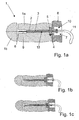
- a mold 1 for plastic injection molding with a top 1a and a Lower part 1b has an insert 2 integrated into the upper part 1a, which part of the mold 1 is.
- a through hole 3 is provided, in which the insert 2 is included.
- the insert 2 is in the area of the through hole 3 cylindrical, wherein its outer diameter to the inner diameter the through hole 3 corresponds.
- a paragraph 4 is provided, in which a head 5 of the insert 2 is added.
- the backlash-free fixation takes place by means of a lid 6 (shown only partially) in which an access opening 7 2 is provided for use.
- the insert 2 has at its protruding into the mold 1 inner end. 8 a tapered, over the through hole 3 projecting area which has the negative form of the shape to be cast. Present is this tapered area is cylindrically shaped, resulting in the to casting shape a cylindrical recess in the form of a blind hole results, as for example for screwing in fastening screws is required.
- the insert 2 has a bore 9 which is centered along its longitudinal axis runs and ends at the inner end of the insert 2, wherein it is present after production of the bore 9 is closed. She can, however Also be designed as a blind hole.
- the insert 2 has a first part of a pneumatic connection 10, which like the bore 9 part of a monitoring device is, of the drawing in the further one end of the tube eleventh and the second part of the pneumatic connection 10 (quick release coupling) are shown.
- a pneumatic connection 10 which like the bore 9 part of a monitoring device is, of the drawing in the further one end of the tube eleventh and the second part of the pneumatic connection 10 (quick release coupling) are shown.
- a Connected pressure generating device in this case a cylinder
- the an overpressure - compared to the expected pressure in the mold - provides.
- part of the monitoring device is a Pressure sensor (not shown), which corresponds to the interior 12, i. in the Hose 11 and the bore 9, prevailing pressure is continuously detected and transmitted to an evaluation, which monitors the same and in the Case of a pressure change, in this case in particular in the case of a pressure drop, the casting process stops and causes a corresponding warning signal.
- the function of the monitoring device is the following: By means of the device To generate pressure is air, which is in the cylinder, in the associated Hose 11 and the hole 9 is located, compacted, so that in the interior formed by the cylinder, the hose 11 and the bore 9 12 a higher pressure prevails, as in the casting process in the mold is to be expected. This pressure is over a plurality of casting cycles maintained.
- the insert 2 breaks during a filling process, the resulting gap is removed Air due to the prevailing in the interior 12 pressure in the mold 1 off, so that the pressure drops.
- the pressure change is based on the continuously supplied to the evaluation unit pressure values determined by the same, so that the monitoring device a corresponding Wansignal releases and the casting process is stopped. For repair, the use of 2 simply replaced and the new insert 2 can be reconnected.
- any fluid can be used become. This is preferably air or another gas / mixture, however, liquids can also be used, such as. Water, oil or any other hydraulic fluid.
- the pressure generating device can also a vacuum (or a much lower pressure than in the mold too expect) generate, so that no air from the employment in the case of a Breakage emanates into the mold, but air and / or material from the Filling mold flows through the crack in the interior 12, so that the pressure in the interior 12 increases.
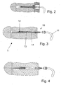
- a second embodiment is shown, which is a variant the insert with a relatively short over the through hole protruding Area shows. Otherwise, the second embodiment corresponds the first embodiment described above and also the different operating variants are here, as well as in the following With reference to the drawings illustrated embodiments, possible.
- the insert 2 according to the third embodiment shown in Fig. 3 is not pushed from the outside, but from the interior of the Mold 1 introduced and by means of a bolt introduced from the outside 13th attached so that no lid is required, but rather a corresponding one Embodiment of the part of the connection 10, optionally with a washer, sufficient.
- the bolt 13 has a through hole 14 which, like the bore 9 and the tube 11, is part of the interior 12, in which there is an overpressure or underpressure.
- Fig. 4 shows the fourth embodiment, according to which the insert 2 and the mold-side part of the terminal 10 is not connected to each other are, i.
- the through hole 3 is free and in its central area thus in this area part of the interior 12.
- the insert 2 as well as the Part of the terminal 10 are screwed into the mold 1 and thus with her detachably connected.
- a monitoring device 21 is shown, by means of a Plurality of critical areas, such as those of the above Operations, can be monitored at the same time.
- This is a Fluid, in this case compressed air, which has a pressure of 6 bar and of the general Compressed air supply comes by means of a pressure regulator 22 to a Pressure of 1.5 bar relaxed.
- An electric valve 23 monitors the pressure in the central supply line 24, which is to the individual monitoring points into a plurality of pressure lines and / or hoses 11 branched.
- the general forms Compressed air supply in connection with the pressure reducing electric valve 23 the device for generating pressure.
- a pressure monitor 25 pressure sensor
Landscapes
- Engineering & Computer Science (AREA)
- Mechanical Engineering (AREA)
- Manufacturing & Machinery (AREA)
- Injection Moulding Of Plastics Or The Like (AREA)
Abstract
Description
- Fig. 1a
- eine geschnittene Darstellung einer Gießform mit einem Einsatz gemäß dem ersten Ausführungsbeispiel,
- Fig. 1b
- eine Fig. 1a entsprechende Ansicht vor dem Anschließen der Drucküberwachung,
- Fig. 1c
- eine Fig. 1a entsprechende Ansicht mit gebrochenem Einsatz,
- Fig. 2
- eine geschnittene Darstellung einer Gießform mit einem Einsatz gemäß dem zweiten Ausführungsbeispiel,
- Fig. 3
- eine geschnittene Darstellung einer Gießform mit einem Einsatz gemäß dem dritten Ausführungsbeispiel, und
- Fig. 4
- eine geschnittene Darstellung einer Gießform mit einem Einsatz gemäß dem vierten Ausführungsbeispiel,
- Fig. 5
- eine schematische Darstellung einer Überwachungsvorrichtung, und
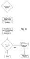
- Fig. 6
- ein Flussdiagramm, das den Ablauf der Überwachung zeigt.
Claims (16)
- Vorrichtung zum Gießen, insbesondere Spritzgießform, die einen in Vergleich mit seinem Querschnitt länglichen Bereich aufweist, der sich in den Innenraum der Gießform (1) erstreckt, um eine Aussparung in der gegossenen Form zu bilden, dadurch gekennzeichnet, dass eine Überwachungsvorrichtung (21) vorgesehen ist, die ein Brechen des länglichen Bereichs überwacht.
- Vorrichtung zum Gießen nach Anspruch 1, dadurch gekennzeichnet, dass die Überwachungsvorrichtung (21) einen Drucksensor (25), einen Strahlungssensor, einen Magnetsensor und/oder einen elektrischen Sensor aufweist.
- Vorrichtung zum Gießen nach Anspruch 1 oder 2, dadurch gekennzeichnet, dass im länglichen Bereich eine Bohrung (9) vorgesehen ist.
- Vorrichtung zum Gießen nach Anspruch 3, dadurch gekennzeichnet, dass die Bohrung (9) an ihrem gießformseitigen Ende geschlossen ist.
- Vorrichtung zum Gießen nach einem der vorhergehenden Ansprüche, dadurch gekennzeichnet, dass der längliche Bereich als Einsatz (2) ausgebildet ist, der Teil der Vorrichtung zum Gießen (1) ist.
- Vorrichtung zum Gießen nach einem der vorhergehenden Ansprüche, dadurch gekennzeichnet, dass der längliche Bereich einen kreisförmigen Querschnitt aufweist.
- Vorrichtung zum Gießen nach einem der vorhergehenden Ansprüche, dadurch gekennzeichnet, dass eine Bohrung (9) mittig im länglichen Bereich und in seiner Längserstreckung verlaufend angeordnet ist.
- Vorrichtung zum Gießen nach einem der vorhergehenden Ansprüche, dadurch gekennzeichnet, dass ein Anschluss (10) für ein Kabel oder einen Schlauch (1.1) vorgesehen ist, welcher Teil der Überwachungsvorrichtung (21) ist.
- Vorrichtung zum Gießen nach einem der vorhergehenden Ansprüche, dadurch gekennzeichnet, dass die Überwachungsvorrichtung (21) eine Vorrichtung zur Druckerzeugung aufweist.
- Vorrichtung zum Gießen nach Anspruch 9, dadurch gekennzeichnet, dass die Vorrichtung zur Druckerzeugung durch die allgemeine Druckluftversorgung gebildet ist, wobei der Druck abgesenkt werden kann.
- Vorrichtung zum Gießen nach einem der vorhergehenden Ansprüche, dadurch gekennzeichnet, dass die Überwachungsvorrichtung ein Fluid aufweist, das sich in einem Innenraum (12) der Gießform (1) befindet, wobei es unter einem Druck steht, der sich vom in der Gießform (1) herrschenden Druck unterscheidet.
- Verfahren zum Gießen, insbesondere zum Einspritzgießen, wobei zumindest während des Gießvorgangs eine Überwachung der Gießform (1) bezüglich des Auftretens von Brüchen in einem kritischen Bereich mittels einer Überwachungsvorrichtung (21) gemäß einem der Ansprüche 1 bis 11 erfolgt.
- Verfahren nach Anspruch 12, dadurch gekennzeichnet, dass mittels eines oder mehrerer Sensoren der kritische Bereich der Gießform (1) überwacht wird, wobei die von dem oder den Sensoren ermittelten Messwerte auf Abweichungen über der Zeit überwacht werden.
- Verfahren nach Anspruch 13, dadurch gekennzeichnet, dass die von dem oder den Sensoren ermittelten Messwerte auf Abweichungen über der Zeit überwacht werden.
- Verfahren nach einem der Ansprüche 12 bis 15, dadurch gekennzeichnet, dass im zu überwachenden Bereich der Gießform (1) ein Hohlraum (12) vorgesehen ist, in dem ein Fluid mit einem Über- oder Unterdruck verglichen mit dem im Inneren der Gießform (1) herrschenden Druck vorgesehen ist, wobei Druckänderungen im Fluid überwacht werden.
- Verfahren nach Anspruch 15, dadurch gekennzeichnet, dass als Fluid Druckluft verwendet wird, die von der allgemeinen Druckluftversorgung zur Verfügung gestellt wird.
Priority Applications (1)
| Application Number | Priority Date | Filing Date | Title |
|---|---|---|---|
| EP03293266A EP1547749A1 (de) | 2003-12-19 | 2003-12-19 | Vorrichtung und Verfahren zur Überwachung des Brechens von Einsätzen in Giessformen |
Applications Claiming Priority (1)
| Application Number | Priority Date | Filing Date | Title |
|---|---|---|---|
| EP03293266A EP1547749A1 (de) | 2003-12-19 | 2003-12-19 | Vorrichtung und Verfahren zur Überwachung des Brechens von Einsätzen in Giessformen |
Publications (1)
| Publication Number | Publication Date |
|---|---|
| EP1547749A1 true EP1547749A1 (de) | 2005-06-29 |
Family
ID=34530824
Family Applications (1)
| Application Number | Title | Priority Date | Filing Date |
|---|---|---|---|
| EP03293266A Withdrawn EP1547749A1 (de) | 2003-12-19 | 2003-12-19 | Vorrichtung und Verfahren zur Überwachung des Brechens von Einsätzen in Giessformen |
Country Status (1)
| Country | Link |
|---|---|
| EP (1) | EP1547749A1 (de) |
Cited By (2)
| Publication number | Priority date | Publication date | Assignee | Title |
|---|---|---|---|---|
| FR2919516A1 (fr) * | 2007-07-31 | 2009-02-06 | Valois Sas | Systeme et procede de moulage de pieces constitutives d'un distributeur de produit fluide. |
| EP2853875A1 (de) * | 2013-09-30 | 2015-04-01 | Werkzeugbau Siegfried Hofmann GmbH | Vorrichtung zur Früherkennung von Rissbildungen in medienführenden Werkstücken |
Citations (4)
| Publication number | Priority date | Publication date | Assignee | Title |
|---|---|---|---|---|
| US4580956A (en) * | 1981-10-20 | 1986-04-08 | Sanden Corporation | Biased drive mechanism for an orbiting fluid displacement member |
| JPS62167018A (ja) * | 1986-01-20 | 1987-07-23 | Matsushita Electric Works Ltd | 射出成形用金型 |
| JPH09122873A (ja) * | 1995-10-31 | 1997-05-13 | Honda Motor Co Ltd | 鋳抜き孔用ピン状水冷中子の折れ検出装置 |
| JPH09254188A (ja) * | 1996-03-22 | 1997-09-30 | Toshiba Mach Co Ltd | コネクタ成形用金型のコネクタピン折損検出装置 |
-
2003
- 2003-12-19 EP EP03293266A patent/EP1547749A1/de not_active Withdrawn
Patent Citations (4)
| Publication number | Priority date | Publication date | Assignee | Title |
|---|---|---|---|---|
| US4580956A (en) * | 1981-10-20 | 1986-04-08 | Sanden Corporation | Biased drive mechanism for an orbiting fluid displacement member |
| JPS62167018A (ja) * | 1986-01-20 | 1987-07-23 | Matsushita Electric Works Ltd | 射出成形用金型 |
| JPH09122873A (ja) * | 1995-10-31 | 1997-05-13 | Honda Motor Co Ltd | 鋳抜き孔用ピン状水冷中子の折れ検出装置 |
| JPH09254188A (ja) * | 1996-03-22 | 1997-09-30 | Toshiba Mach Co Ltd | コネクタ成形用金型のコネクタピン折損検出装置 |
Non-Patent Citations (4)
| Title |
|---|
| "WERKZEUGSICHERUNG", PLASTVERARBEITER, ZECHNER UND HUETHIG VERLAG GMBH. SPEYER/RHEIN, DE, vol. 46, no. 1, 1995, pages 86, XP000493872, ISSN: 0032-1338 * |
| PATENT ABSTRACTS OF JAPAN vol. 012, no. 001 (M - 656) 6 January 1988 (1988-01-06) * |
| PATENT ABSTRACTS OF JAPAN vol. 1997, no. 09 30 September 1997 (1997-09-30) * |
| PATENT ABSTRACTS OF JAPAN vol. 1998, no. 01 30 January 1998 (1998-01-30) * |
Cited By (5)
| Publication number | Priority date | Publication date | Assignee | Title |
|---|---|---|---|---|
| FR2919516A1 (fr) * | 2007-07-31 | 2009-02-06 | Valois Sas | Systeme et procede de moulage de pieces constitutives d'un distributeur de produit fluide. |
| EP2853875A1 (de) * | 2013-09-30 | 2015-04-01 | Werkzeugbau Siegfried Hofmann GmbH | Vorrichtung zur Früherkennung von Rissbildungen in medienführenden Werkstücken |
| DE102013016166A1 (de) * | 2013-09-30 | 2015-04-02 | Werkzeugbau Siegfried Hofmann Gmbh | Vorrichtung zur Früherkennung von Rissbildungen in medienführenden Werkstücken |
| DE102013016166B4 (de) * | 2013-09-30 | 2015-11-19 | Werkzeugbau Siegfried Hofmann Gmbh | Vorrichtung zur Früherkennung von Rissbildungen in medienführenden Werkstücken |
| US9568393B2 (en) | 2013-09-30 | 2017-02-14 | Werkzeugbau Siegfried Hofmann Gmbh | Method and device for the early detection of crack formations in media-carrying workpieces |
Similar Documents
| Publication | Publication Date | Title |
|---|---|---|
| AT510024B1 (de) | Plastifiziereinheit mit verschleissmesssensor | |
| DE4229834A1 (de) | Verfahren und einrichtung zum elektrischen verarbeiten von vakuumdruckinformation fuer eine vakuumeinheit | |
| WO1999059795A1 (de) | Spritzgiesswerkzeug | |
| EP1762360A1 (de) | Spritzgießform mit elektronischem Zähler | |
| DE102005032367A1 (de) | Verfahren zum Überwachen und/oder Regeln der Schmelzebefüllung von zumindest einer Kavität | |
| DE3301886C2 (de) | Vorrichtung zur Messung der Temperatur in einem mit Staub beladenen Gasstrom | |
| DE3545747C2 (de) | Extruderüberwachung | |
| DE2333488A1 (de) | Einstueckiger schlauch und einrichtung und verfahren zu seiner herstellung | |
| EP0945246B1 (de) | Herstellvorrichtung mit Kontrolleinrichtungen für einen Kunststoff-Hohlkörper | |
| EP3593924B1 (de) | Vorrichtung mit filtermodul zur herstellung von druckgussteilen | |
| EP1547749A1 (de) | Vorrichtung und Verfahren zur Überwachung des Brechens von Einsätzen in Giessformen | |
| EP0190173A1 (de) | Verfahren zur überwachung und/oder regelung des spritzgiessens bei spritzgiessmaschinen. | |
| DE10107032A1 (de) | Verfahren, Computerprogramm und Vorrichtung zum Messen der Einspritzmenge von Einspritzdüsen, insbesondere für Kraftfahrzeuge | |
| EP0060289B1 (de) | Opferanode mit verbrauchsanzeige und tauchhülse für einen wärmefühler | |
| DE102005060674C5 (de) | Positionssensor in Stabbauweise sowie Verfahren zum Austausch | |
| DE3910146C2 (de) | Verfahren zum Überwachen des Einspritzdrucks bei einer Spritz- oder Druckgießmaschine | |
| EP0671599B1 (de) | Verfahren und pneumatisches Messwerkzeug zur Überwachung von Abmessungen eines Werkstückes | |
| DE69509833T2 (de) | Dorn mit unterschiedlichen Poren zur Dichtheitsprüfung prophylaktischer Artikel | |
| EP3597387B1 (de) | Vorrichtung zum mischen von kautschukmischungen mit überwachungssensor für mischwerkzeugstege, verwendung eines sensors zur überwachung eines abstandes zwischen einem mischwerkzeugsteg und der innenwand eines vorrichtungsgehäuses sowie verfahren zur überwachung eines abstandes zwischen einem mischwerkzeugsteg und der innenwand eines vorrichtungsgehäuses | |
| DE4015321C2 (de) | ||
| DE102012109575B4 (de) | Spritzgießwerkzeug, Leckageerkennungseinrichtung für ein solches Spritzgießwerkzeug und Verfahren zur Erkennung einer Leckage in einem Spritzgießwerkzeug | |
| DE20319447U1 (de) | Einrichtung zur Dichtigkeitsüberwachung eines mit einem Druckmedium befüllbaren Dichtungselements | |
| DE19511704A1 (de) | Vorrichtung zur Prüfung der Maßhaltigkeit einer in einem Werkstück befindlichen Ausnehmung | |
| DE102020114635A1 (de) | Feldgerät mit Anzeigemittel zur optischen Wiedergabe von Grenzwerten und Verfahren | |
| EP0281735B1 (de) | Anordnung zur Überwachung eines der Schmierung einer Schmierstelle dienenden Oelflusses |
Legal Events
| Date | Code | Title | Description |
|---|---|---|---|
| PUAI | Public reference made under article 153(3) epc to a published international application that has entered the european phase |
Free format text: ORIGINAL CODE: 0009012 |
|
| AK | Designated contracting states |
Kind code of ref document: A1 Designated state(s): AT BE BG CH CY CZ DE DK EE ES FI FR GB GR HU IE IT LI LU MC NL PT RO SE SI SK TR |
|
| AX | Request for extension of the european patent |
Extension state: AL LT LV MK |
|
| RAP1 | Party data changed (applicant data changed or rights of an application transferred) |
Owner name: BEHR FRANCE ROUFFACH SAS |
|
| 17P | Request for examination filed |
Effective date: 20051229 |
|
| AKX | Designation fees paid |
Designated state(s): AT BE BG CH CY CZ DE DK EE ES FI FR GB GR HU IE IT LI LU MC NL PT RO SE SI SK TR |
|
| STAA | Information on the status of an ep patent application or granted ep patent |
Free format text: STATUS: THE APPLICATION IS DEEMED TO BE WITHDRAWN |
|
| 18D | Application deemed to be withdrawn |
Effective date: 20060815 |