EP2853431A2 - Power take-off shaft drive for an agricultural work machine - Google Patents
Power take-off shaft drive for an agricultural work machine Download PDFInfo
- Publication number
- EP2853431A2 EP2853431A2 EP14176257.5A EP14176257A EP2853431A2 EP 2853431 A2 EP2853431 A2 EP 2853431A2 EP 14176257 A EP14176257 A EP 14176257A EP 2853431 A2 EP2853431 A2 EP 2853431A2
- Authority
- EP
- European Patent Office
- Prior art keywords
- shaft
- transmission
- gear
- pto
- drive
- Prior art date
- Legal status (The legal status is an assumption and is not a legal conclusion. Google has not performed a legal analysis and makes no representation as to the accuracy of the status listed.)
- Granted
Links
- 230000005540 biological transmission Effects 0.000 claims abstract description 220
- 238000010168 coupling process Methods 0.000 claims description 15
- 238000000034 method Methods 0.000 claims description 14
- 230000008878 coupling Effects 0.000 claims description 13
- 238000005859 coupling reaction Methods 0.000 claims description 13
- 238000013461 design Methods 0.000 description 11
- 230000004323 axial length Effects 0.000 description 6
- 230000008901 benefit Effects 0.000 description 5
- 238000003306 harvesting Methods 0.000 description 5
- 230000000694 effects Effects 0.000 description 4
- 230000008569 process Effects 0.000 description 4
- 238000013519 translation Methods 0.000 description 4
- 230000014616 translation Effects 0.000 description 4
- 230000008859 change Effects 0.000 description 2
- 238000010276 construction Methods 0.000 description 2
- 230000009467 reduction Effects 0.000 description 2
- 230000001609 comparable effect Effects 0.000 description 1
- 238000011161 development Methods 0.000 description 1
- 230000018109 developmental process Effects 0.000 description 1
- 238000010586 diagram Methods 0.000 description 1
- 239000000446 fuel Substances 0.000 description 1
- 230000000977 initiatory effect Effects 0.000 description 1
- 238000009434 installation Methods 0.000 description 1
- 238000012545 processing Methods 0.000 description 1
- 238000000926 separation method Methods 0.000 description 1
- 210000002023 somite Anatomy 0.000 description 1
- 238000012546 transfer Methods 0.000 description 1
- 230000001960 triggered effect Effects 0.000 description 1
Images


Classifications
-
- B—PERFORMING OPERATIONS; TRANSPORTING
- B60—VEHICLES IN GENERAL
- B60K—ARRANGEMENT OR MOUNTING OF PROPULSION UNITS OR OF TRANSMISSIONS IN VEHICLES; ARRANGEMENT OR MOUNTING OF PLURAL DIVERSE PRIME-MOVERS IN VEHICLES; AUXILIARY DRIVES FOR VEHICLES; INSTRUMENTATION OR DASHBOARDS FOR VEHICLES; ARRANGEMENTS IN CONNECTION WITH COOLING, AIR INTAKE, GAS EXHAUST OR FUEL SUPPLY OF PROPULSION UNITS IN VEHICLES
- B60K17/00—Arrangement or mounting of transmissions in vehicles
- B60K17/28—Arrangement or mounting of transmissions in vehicles characterised by arrangement, location, or type of power take-off
-
- B—PERFORMING OPERATIONS; TRANSPORTING
- B60—VEHICLES IN GENERAL
- B60Y—INDEXING SCHEME RELATING TO ASPECTS CROSS-CUTTING VEHICLE TECHNOLOGY
- B60Y2200/00—Type of vehicle
- B60Y2200/20—Off-Road Vehicles
- B60Y2200/22—Agricultural vehicles
- B60Y2200/221—Tractors
-
- F—MECHANICAL ENGINEERING; LIGHTING; HEATING; WEAPONS; BLASTING
- F16—ENGINEERING ELEMENTS AND UNITS; GENERAL MEASURES FOR PRODUCING AND MAINTAINING EFFECTIVE FUNCTIONING OF MACHINES OR INSTALLATIONS; THERMAL INSULATION IN GENERAL
- F16H—GEARING
- F16H3/00—Toothed gearings for conveying rotary motion with variable gear ratio or for reversing rotary motion
- F16H3/02—Toothed gearings for conveying rotary motion with variable gear ratio or for reversing rotary motion without gears having orbital motion
- F16H3/08—Toothed gearings for conveying rotary motion with variable gear ratio or for reversing rotary motion without gears having orbital motion exclusively or essentially with continuously meshing gears, that can be disengaged from their shafts
- F16H2003/0826—Toothed gearings for conveying rotary motion with variable gear ratio or for reversing rotary motion without gears having orbital motion exclusively or essentially with continuously meshing gears, that can be disengaged from their shafts wherein at least one gear on the input shaft, or on a countershaft is used for two different forward gear ratios
-
- F—MECHANICAL ENGINEERING; LIGHTING; HEATING; WEAPONS; BLASTING
- F16—ENGINEERING ELEMENTS AND UNITS; GENERAL MEASURES FOR PRODUCING AND MAINTAINING EFFECTIVE FUNCTIONING OF MACHINES OR INSTALLATIONS; THERMAL INSULATION IN GENERAL
- F16H—GEARING
- F16H2200/00—Transmissions for multiple ratios
- F16H2200/003—Transmissions for multiple ratios characterised by the number of forward speeds
- F16H2200/0043—Transmissions for multiple ratios characterised by the number of forward speeds the gear ratios comprising four forward speeds
-
- F—MECHANICAL ENGINEERING; LIGHTING; HEATING; WEAPONS; BLASTING
- F16—ENGINEERING ELEMENTS AND UNITS; GENERAL MEASURES FOR PRODUCING AND MAINTAINING EFFECTIVE FUNCTIONING OF MACHINES OR INSTALLATIONS; THERMAL INSULATION IN GENERAL
- F16H—GEARING
- F16H2200/00—Transmissions for multiple ratios
- F16H2200/003—Transmissions for multiple ratios characterised by the number of forward speeds
- F16H2200/0047—Transmissions for multiple ratios characterised by the number of forward speeds the gear ratios comprising five forward speeds
-
- F—MECHANICAL ENGINEERING; LIGHTING; HEATING; WEAPONS; BLASTING
- F16—ENGINEERING ELEMENTS AND UNITS; GENERAL MEASURES FOR PRODUCING AND MAINTAINING EFFECTIVE FUNCTIONING OF MACHINES OR INSTALLATIONS; THERMAL INSULATION IN GENERAL
- F16H—GEARING
- F16H2200/00—Transmissions for multiple ratios
- F16H2200/003—Transmissions for multiple ratios characterised by the number of forward speeds
- F16H2200/0052—Transmissions for multiple ratios characterised by the number of forward speeds the gear ratios comprising six forward speeds
-
- F—MECHANICAL ENGINEERING; LIGHTING; HEATING; WEAPONS; BLASTING
- F16—ENGINEERING ELEMENTS AND UNITS; GENERAL MEASURES FOR PRODUCING AND MAINTAINING EFFECTIVE FUNCTIONING OF MACHINES OR INSTALLATIONS; THERMAL INSULATION IN GENERAL
- F16H—GEARING
- F16H3/00—Toothed gearings for conveying rotary motion with variable gear ratio or for reversing rotary motion
- F16H3/006—Toothed gearings for conveying rotary motion with variable gear ratio or for reversing rotary motion power being selectively transmitted by either one of the parallel flow paths
Definitions
- the invention relates to a power take-off gearbox for an agricultural work machine according to claim 1. Furthermore, the invention relates to an agricultural work machine according to claim 10, a combination of a work machine and a work implement according to claim 12 and a method for braking a PTO shaft according to claim 16.
- Agricultural machines such as tractors in particular are usually equipped with a power take-off shaft for driving an attachable implement.
- the drive power of a main drive motor of the tractor is provided inter alia for the operation of the PTO.
- the main drive motor can be connected, for example via fixed translations with the PTO.
- the main drive motor In order to achieve a PTO shaft speed desired for the implement, the main drive motor must then be operated at its rated speed. Consequently, the provided for the working process PTO speed, the speed of the main drive motor before.
- a transmission known for a PTO is a transmission known for a PTO.
- a transmission input shaft and two input shafts coupled thereto are arranged coaxially on an axis in order to be able to drive via a plurality of selectable transmission gear stages, which are each formed by a Stirnradcruung, a peg shaft offset thereto.
- the PTO transmission described so is at least partially (in each case when changing the input shaft) switchable under load.
- a disadvantage is the relatively large axial length of the PTO, due to the side by side arranged in the axial direction Stirnradbinonne for each gear ratio.
- a double clutch unit and a hollow shaft assembly are required, which are each technically complex and therefore costly.
- the third embodiment although eliminating double clutch unit and hollow shaft assembly, but four friction clutches and a complex control are required to achieve four gear ratios.
- a PTO transmission with the features of claim 1.
- This is characterized by a first partial transmission, which is associated with a first transmission shaft, and at least one further, in particular second, partial transmission, the one spaced from the first transmission shaft further, in particular second, transmission shaft is associated with each of the transmission shafts via at least one transmission gear stage with a common PTO in drive connection can be brought and wherein each of the transmission shafts by closing a respective sub-transmission associated friction clutch with an input shaft of the power take-off can be brought into drive connection.
- the PTO transmission has at least two partial transmission with spaced transmission shafts, which can be brought into drive connection with a common PTO. This results in a dissolved design of at least two-way PTO, which brings various advantages.
- the PTO has three or more partial transmission.
- a transmission stage may in principle comprise any arrangement of transmission members with which a ratio between two shafts can be represented. Conceivable in this context, in particular wheel (Stirnrad-, Reibrad-), belt (toothed belt) and / or chain drives.
- the described operation of the PTO can be implemented advantageously by the first gear shaft by means of the first part of the transmission associated friction clutch with a first drive shaft is coupled and the further transmission shaft by means of the further sub-transmission associated friction clutch with another drive shaft can be coupled, wherein the first and the further drive shaft are part of an input gear driven by the intermediate gear.
- the intermediate gear in particular takes on the task of being able to drive the first and the further drive shaft, which can each be coupled with the first and the further transmission shaft, via a common input shaft. According to a preferred embodiment, while the input shaft coincides with the first drive shaft of the power take-off gear.
- the intermediate gear is a spur gear in which a first shaft and a further shaft parallel thereto are in a fixed gear ratio, in particular the same sense of rotation of the shafts.
- the transmission ratio between the first shaft and the further shaft is unequal to 1. In this way, a step jump between even and odd gear ratios can be easily realized.
- Each of the first and the further transmission shaft is advantageously associated with at least one toothed wheel which meshes with a gear associated with the PTO shaft, so that a fixed speed ratio in the sense of a gear ratio can be produced between the PTO shaft and the respective transmission shaft.
- first gear shaft are assigned a plurality of gears, each meshing with a pinion shaft associated gear to each form a pair of gears a shiftable transmission gear, wherein a further gear shaft associated with a plurality of gears, each via a Intermediate acting intermediate gear meshing with one of the PTO shaft associated gear to form an arrangement of gears depending on a shiftable transmission gear, wherein the preselection of a gear ratio, the relevant gear rotatably by adjusting means rotatably connected to the respective transmission shaft.
- the first and / or the further gear shaft associated with a plurality of gears, each meshing with a pinion associated with the gear, wherein the preselection of a gear ratio one or a plurality of the gears rotatably by adjusting means with the respective transmission shaft and / or the PTO is connectable to form a switchable transmission gear as an arrangement of gears.
- the drive connection of a transmission gear stage is not produced solely via exactly one of the transmission shafts and the power take-off shaft, but that it is produced via at least two transmission shafts and the power take-off shaft.
- a gear assigned to the PTO shaft can be brought into a position which is loose with respect to the PTO shaft in order to transmit drive power from one of the transmission shafts to the other in meshing engagement with gears of at least two transmission shafts. It offers the possibility, with the same number of gears - and thus unchanged size - to increase the number of switchable gears.
- the basic structure of the power take-off with a first partial transmission and at least one other sub-transmission whose transmission shafts are spaced apart (dissolved construction), offers the possibility of an approximately symmetrical transmission architecture. This not only facilitates the assembly of the transmission, but allows the partial use of the same machine elements (equal parts) or at least similar machine elements (similar parts) in the partial transmissions.
- components such as input shafts, gears, friction clutches, transmission shafts, shift sleeves may be mentioned.
- the transmission input shaft and the input shaft of the power take-off which is in particular the first drive shaft, a clutch, in particular a form-fitting coupling such as a shift sleeve or the like.
- the invention relates to a combination of a working machine and an attached to the PTO of the PTO gear drive attachment.
- high stopping times may occur if the PTO shaft is to be shut down with the implement attached. These occur in particular when the drive train with attached implement has a high inertia, for example when mounted on the machine balers or gyro or drum mowers.
- the long follow-up times can represent an increased safety hazard, for example if a machine operator or hold a person in the vicinity of moving machine parts.
- waiting for the actual standstill results in a mostly unwanted loss of time during the harvesting operation.
- a well-known way to shut down the PTO is to turn on the PTO additional braking element to brake the PTO in this way.
- the additional brake element and a required actuating device represent an additional design effort and an associated cost disadvantage.
- a mere braking the PTO causes in the situation mostly unwanted shutdown (colloquially: "stalling") of the drive motor.
- interrupting the drive connection between PTO and drive motor is first ensured that the PTO is drivingly decoupled from the drive motor.
- the decoupling ensures, on the one hand, that the drive motor is not forced to stand still ("strangled out") by stopping the PTO shaft.
- the complete separation of the PTO drive from the drive motor allows the reduction of friction, Trailing and churning losses when not in use the PTO.
- the interruption of the drive connection can be realized in a structurally simple and thus cost-effective manner by means of a simple form-fitting coupling, such as a shift sleeve.
- the actual braking of the power take-off takes place in that a standing with the PTO shaft in fixed speed ratio first gear shaft and standing with the PTO shaft in fixed speed ratio second gear shaft are coupled to an intermediate gear having a different speed ratio of the transmission shafts gear ratio.
- the two fixedly driven by the (still rotating) PTO driven gear shafts coupled, for example, to the input and output shaft of an intermediate gear.
- two standing in fixed speed ratio waves are braked by being coupled with a parallel transmission path in the form of the intermediate gear, which has a different from the speed ratio of the first and second transmission shaft gear ratio.
- the braking of the power take-off takes place accordingly by reducing the relative speeds during both simultaneous coupling operations. This results in the advantageous effect that no additional braking device and no additional actuators are required for braking.
- the friction forces of both coupling operations can be used, whereby a particularly effective braking effect can be achieved.
- the first transmission shaft is assigned to a first partial transmission and the further transmission shaft is assigned to a further partial transmission of the multi-clutch transmission.
- the first transmission shaft with a first shaft and the further transmission shaft are expediently coupled at the same time with another shaft, wherein the first shaft and the further shaft are part of the intermediate gear and are in a fixed ratio to each other.
- the simultaneous coupling operation is advantageously carried out by simultaneously closing a friction clutch acting between the first shaft and the further transmission shaft and a friction clutch acting between the further shaft and the further transmission shaft.
- a clutch arranged between the drive motor and the power take-off gearbox in particular a positively operating clutch such as a shift sleeve or the like, is opened.
- the deceleration of the PTO can basically be initiated in different operating situations.
- the braking is triggered as a function of an operating state of the working machine and / or a work implement attached thereto.
- a control device may be provided, which is signal-connected with state sensors of the working machine and / or the working device.
- a control device can be operated manually via a user interface, so that a machine operator can initiate braking at the occurrence of a specific situation at his own discretion.
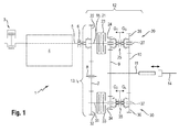
- a drive motor 3 for example a diesel engine, provides a drive power for a PTO transmission 12 via a transmission input shaft 5. Besides provides the drive motor 3 drive power for example, a traction drive 4 of the tractor 1 ready.
- the transmission input shaft 5 can be brought into drive connection via a form-fitting clutch, for example in the form of a shift sleeve 6 or a dog clutch, to the PTO gearbox 12, in particular to an input shaft 15 of the PTO gearbox 12.
- the input shaft 15 coincides with a first drive shaft 21 of a subtransmission 13, which is still to be explained.
- opening and closing the shift sleeve 6 can be a drive connection between the drive motor 3 and the PTO gear 12 interrupt or produce.
- the intermediate gear 13 essentially comprises a toothed wheel 22 which is arranged on a first drive shaft 21, a toothed wheel 32 which is arranged on a second drive shaft 31 spaced parallel thereto, and an intermediate wheel 7 which is connected to the drive shafts 21, 31 parallel axis of rotation 8 is rotatably mounted.
- the first drive shaft 21 of the intermediate gear 13 coincides in the illustrated embodiment with the input shaft 15 of the power take-off 12.
- the intermediate gear 7 meshes with the gear 22 of the first drive shaft 21 and with the gear 32 of the second drive shaft 31.
- the gears 22 and 32 and the associated drive shafts 21 and 31 of the intermediate gear 13 are due to the gear 22, idler gear 7 and gear 32 formed gear assembly drivingly coupled, ie between them there is a constant gear ratio i z .
- the drive shafts 22 and 32 have a same direction of rotation.
- the gear 22 has a larger diameter than the gear 32, with the result that the drive shaft 31 always rotates faster in a fixed speed ratio than the drive shaft 21st
- the first drive shaft 21 can be brought into drive connection via a first multi-plate clutch 23 with a first transmission shaft 27 coaxial therewith.
- the first gear shaft 27 is associated with a set consisting of two gears 24 and 26.
- the gears 24 and 26 are positively connected by means of an interposed sliding movable shift sleeve 25 with the first transmission shaft 27.
- the gears 24 and 26 mesh respectively with a gear 9 and 10, wherein the gears 9 and 10 are connected to the first transmission shaft 27 parallel to the PTO shaft 11.
- a gear pair formed from the gear 24 and the gear 9 has a different ratio than a formed from the gear 26 and the gear 10 gear pair. In this way, the gear pairs 24, 9 and the gear pairings 26, 10 different gear ratios G n within the PTO 12.
- the gear pair 34, 9 forms a second gear G 2
- the gear pair 36, 10 forms a fourth gear G 4 of the PTO 12.
- the transmission gear G 2 or G 4 can be produced by 35 by moving the shift sleeve a corresponding gear G 2 or G 4 inserted (preselection) and the second multi-plate clutch 33 is closed (engaging).
- a previously described by way of example with reference to the first transmission gear G 1 and the second gear G 2 shift can be performed accordingly between other gear ratios and in the reverse direction (from a higher to a lower gear). If it is desired to switch between two even (G 2 , G 4 ) or two odd (G 1 , G 3 ) gear stages under load, this can preferably be done automatically by briefly interposing an intermediate gear stage G 2 or G 3 .
- balers 2 have in their drive train on a high moment of inertia (and / or load torque). Accordingly, when starting, for example, a baler 2, a high torque must be applied.
- tractor 1 and baler 2 advantageously allows a start of the stationary baler 2 using a functionality of the PTO gear 12 described below. Accordingly, at a respective preselected gear ratio G n in each of the partial gear 20, 30 simultaneously both multi-plate clutches 23, 33 closed , During this closing operation, it is possible (with driven input shaft 15 of the power take-off 12), via the multi-plate clutch 23, a torque from the first drive shaft 21 to the first transmission shaft 27 and via the second multi-plate clutch 33 to transmit torque from the second drive shaft 31 to the second transmission shaft 37.
- the first gear shaft 27 and the second gear shaft 37 generate via their respective selected gear ratio G n at the PTO a rectified torque.
- both multi-disc clutches 23, 33 are available for this coupling process, so that due to the increased friction surface a respectively reduced stress on the multi-disc clutches 22, 23, and thus less wear occurs on these. Furthermore, using both multi-plate clutches 23, 33, if required, a particularly high torque at the PTO shaft 11 can be generated. It can thus also balers 2 - or general equipment - with high moment of inertia (and / or load torque) are started or can take place in a shorter time. The process of simultaneous closing of the multi-plate clutches 22, 33 is expediently carried out only as long as until at one of the multi-plate clutches 23, 33 a synchronization is achieved.
- Fig. 2 is shown a schematic view of a situation in which a tractor 1 drives a drawn from the tractor 1 baler 2 on the rear-side PTO 11.
- the in Fig. 2 shown tractor 1 has a PTO powertrain including power take-off 12 such as with reference to Fig. 1 explained on.
- the baler 2 has various working and delivery units, which must be supplied with drive power during harvesting, ie in particular during the processing of crop to pressed bales.
- the baler 2 has a main gear 17, from which, for example, an oscillating plunger (unspecified) can be driven.
- Other work and delivery units not to be explained in more detail here can be drivingly connected to the main transmission 17.
- the main gear 17 is on the drive shaft 14 which is in drive connection with the PTO 11 of the tractor 1, driven.
- a powertrain formed from the various tractor and equipment components generally has significant inertia, depending on the type and size of construction, so that merely disconnecting the drive connection from the drive motor 3 results in a long run-on of the components still in motion these come to a standstill due to friction.
- High follow-up times can represent an increased safety hazard if, for example, a machine operator or a third party are in the vicinity of moving machine parts.
- a long wait for the actual standstill leads to a mostly unwanted loss of time during harvesting or labor input.
- the simultaneous coupling leads to a reduction of Relative speeds in the closing multi-plate clutches 23, 33 and thus to decelerating the self-locking PTO 12.
- An active braking of the PTO 11 and also about the attachment (here: baler 2) takes place.
- the clutch surfaces of both multi-plate clutches 23 and 33 are available as an effective braking surface, so that a high braking effect can be achieved. Long follow-up times of implements can be avoided in this way and safety can be increased.
- the braking method thus performed has the advantage that - in the presence of a corresponding PTO gear 12 - no additional brake and no additional actuator are required, but that the existing already at the PTO 12 multi-plate clutches 23, 33 are used as brakes.
- the preferred prior to the initiation of the braking operation interruption of the drive connection relative to the drive motor 3 can be done in a relatively inexpensive manner by a compact, positive coupling in the form of a shift sleeve 6.
- the power take-off 12 or a tractor equipped with it 1 is also suitable for driving implements that do not have their own brake despite high inertia of the drive train.
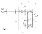
- the idler gear 40 meshes with the gear 34 of the second gear shaft 37 and the gear 9 of the PTO shaft 11, and meshes the idler 41 at the same time with the gear 36 of the second gear shaft 37 and the gear 10 of the PTO shaft 11.
- the PTO 12 according to the Fig. 3 shown second embodiment corresponds to basic functions, in particular with regard to the number of selectable gear ratios the first embodiment.
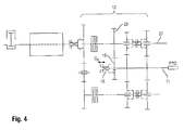
- Fig. 4 shows a power take-off 12 according to a third embodiment of the invention.
- the power take-off 12 according to the third embodiment corresponds in essential features to the basis of Fig. 1 explained first embodiment. To avoid repetition is therefore on the zu Fig. 1 Referenced remarks and is based on a designation of equivalent elements in Fig. 4 waived.
- an additional gear 28 is fixedly arranged on the first transmission shaft 27. This meshes with an additional PTO shaft 11 associated gear 16 which is fastened by means of a shift sleeve 18 relative to the PTO shaft 11 and detachable from it.
- this fifth transmission gear ratio G 5 could be designed for example as a fast economy PTO passage (1000e).
- An advantage of the structural design is that due to the arrangement of the shift sleeve 18 on the PTO 11, the axial length of the PTO 12 in spite of further transmission gear hardly increased and also the other structure is not changed.
- the drive connection of a transmission gear stage is not alone on exactly one of the transmission shafts (27 or 37) and the PTO 11 is made, but that this over both transmission shafts (27 and 37) and the PTO shaft 11 extends.
- one of the PTO 11 associated gear 9 and 10 is brought into a relation to the PTO 11 loose state to drive in meshing with gears 24, 34 and 26, 36 of both transmission shafts 27, 37 of one of the transmission shafts 27, 37th to transmit to each other 37, 27.
- the PTO transmission 12 according to the fourth embodiment thus achieved with the same number of gears - and thus compared to the first embodiment of unchanged size - an increased number of switchable gears.
Abstract
Ein Zapfwellengetriebe (12) für eine landwirtschaftliche Arbeitsmaschine, insbesondere für einen Traktor (1), zeichnet sich aus durch ein erstes Teilgetriebe (20), dem eine erste Getriebewelle (27) zugeordnet ist, und mindestens ein weiteres Teilgetriebe (30), dem eine von der ersten Getriebewelle (27) beabstandete weitere Getriebewelle (37) zugeordnet ist, wobei jede der Getriebewellen (27, 37) über zumindest eine Getriebegangstufe (G n ) mit einer gemeinsamen Zapfwelle (11) in Antriebsverbindung bringbar ist und wobei jede der Getriebewellen (27; 37) durch Schließen einer dem jeweiligen Teilgetriebe (20; 30) zugeordneten Reibkupplung (23; 33) mit einer Eingangswelle (15, 21) des Zapfwellengetriebes (12) in Antriebsverbindung bringbar ist.A PTO transmission (12) for an agricultural work machine, in particular for a tractor (1), is characterized by a first partial transmission (20) to which a first transmission shaft (27) is associated, and at least one further partial transmission (30), the one each of the transmission shafts (27, 37) can be brought into drive connection with a common power take-off shaft (11) via at least one transmission gear (G n) and wherein each of the transmission shafts (27) can be brought into drive connection with the transmission shaft (27). 27, 37) can be brought into driving connection with an input shaft (15, 21) of the PTO transmission (12) by closing a friction clutch (23, 33) associated with the respective partial transmission (20;
Description
Die Erfindung betrifft ein Zapfwellengetriebe für eine landwirtschaftliche Arbeitsmaschine gemäß Anspruch 1. Weiterhin betrifft die Erfindung eine landwirtschaftliche Arbeitsmaschine gemäß Anspruch 10, eine Kombination aus einer Arbeitsmaschine und einem Arbeitsgerät gemäß Anspruch 12 sowie ein Verfahren zum Bremsen einer Zapfwelle nach Anspruch 16.The invention relates to a power take-off gearbox for an agricultural work machine according to claim 1. Furthermore, the invention relates to an agricultural work machine according to
Landwirtschaftliche Arbeitsmaschinen wie insbesondere Traktoren sind üblicherweise mit einer Zapfwelle zum Antrieb eines anbaubaren Arbeitsgeräts ausgestattet. Dabei wird die Antriebsleistung eines Hauptantriebsmotors des Traktors unter anderem für den Betrieb der Zapfwelle bereitgestellt.Agricultural machines such as tractors in particular are usually equipped with a power take-off shaft for driving an attachable implement. The drive power of a main drive motor of the tractor is provided inter alia for the operation of the PTO.
Bei derzeit üblichen Zapfwellenantriebskonzepten kann der Hauptantriebsmotor beispielsweise über fixe Übersetzungen mit der Zapfwelle verbunden werden. Zur Erzielung einer für das Arbeitsgerät gewünschten Normdrehzahl der Zapfwelle muss der Hauptantriebsmotor dann im Bereich seiner Nenndrehzahl betrieben werden. Folglich gibt die für den Arbeitsprozess vorgesehene Zapfwellendrehzahl die Drehzahl des Hauptantriebsmotors vor.In currently customary PTO drive concepts, the main drive motor can be connected, for example via fixed translations with the PTO. In order to achieve a PTO shaft speed desired for the implement, the main drive motor must then be operated at its rated speed. Consequently, the provided for the working process PTO speed, the speed of the main drive motor before.
Um bei Zapfwellenarbeiten mit geringem Leistungsbedarf mit abgesenkter Dieselmotordrehzahl zu arbeiten und auf diese Weise den Betriebspunkt im Motorkennfeld in Bereiche mit geringerem spezifischen Kraftstoffverbrauch zu verschieben, existieren Sparzapfwellen, sogenannte E-Zapfwellen, mit entsprechend angepasster Übersetzung. Abhängig vom jeweiligen Hersteller bzw. der jeweiligen Ausstattung werden so bis zu vier Zapfwellengänge (z.B.: 540/540e/1000/1000e) realisiert. Diese lassen sich üblicherweise jedoch nicht unter Last wechseln, so dass die Sparzapfwellen bei Feldarbeiten mit nur zeitweise hohem Leistungsbedarf (z.B. Erntebetrieb mit Ballenpressen) gar nicht genutzt werden können.In PTO work with low power requirement with reduced diesel engine speed to work and in this way to shift the operating point in the engine map in areas with lower specific fuel consumption, there are savings PTO, so-called electric power take-off, with a correspondingly adapted ratio. Depending on the manufacturer or the respective equipment, up to four PTO speeds (eg 540 / 540e / 1000 / 1000e) are realized. However, these usually can not be changed under load, so that the PTO can not be used in field work with only occasionally high power requirements (for example, harvesting with balers).
Darüber hinaus führt das Anlaufen von Anbaugeräten mit hohen Trägheitsmomenten (z.B. Quaderballenpressen) und/oder Lastmomenten (z.B. Futtermischwagen) zu starken Belastungen beim Kupplungsvorgang, da aufgrund der fehlenden Lastschaltbarkeit häufig in einem Zapfwellengang mit einer geringen Übersetzung angefahren werden muss.In addition, the startup of attachments with high inertia (eg square balers) and / or load moments (eg feed mixer) leads to heavy loads during the coupling process, since due to the lack of power shiftability often has to be approached in a PTO gear with a low gear ratio.
Aus der
Es ist eine Aufgabe der vorliegenden Erfindung, ein lastschaltbares Zapfwellengetriebe für eine landwirtschaftliche Arbeitsmaschine anzugeben, das gegenüber bekannten Zapfwellengetrieben eine verringerte axiale Baulänge aufweist und günstig herstellbar ist.It is an object of the present invention to provide a power shift PTO transmission for an agricultural machine, which has a reduced axial length compared to known PTO and is inexpensive to produce.
Die Aufgabe wird gelöst durch ein Zapfwellengetriebe mit den Merkmalen des Anspruchs 1. Dieses zeichnet sich aus durch ein erstes Teilgetriebe, dem eine erste Getriebewelle zugeordnet ist, und mindestens ein weiteres, insbesondere zweites, Teilgetriebe, dem eine von der ersten Getriebewelle beabstandete weitere, insbesondere zweite, Getriebewelle zugeordnet ist, wobei jede der Getriebewellen über zumindest eine Getriebegangstufe mit einer gemeinsamen Zapfwelle in Antriebsverbindung bringbar ist und wobei jede der Getriebewellen durch Schließen einer dem jeweiligen Teilgetriebe zugeordneten Reibkupplung mit einer Eingangswelle des Zapfwellengetriebes in Antriebsverbindung bringbar ist.This object is achieved by a PTO transmission with the features of claim 1. This is characterized by a first partial transmission, which is associated with a first transmission shaft, and at least one further, in particular second, partial transmission, the one spaced from the first transmission shaft further, in particular second, transmission shaft is associated with each of the transmission shafts via at least one transmission gear stage with a common PTO in drive connection can be brought and wherein each of the transmission shafts by closing a respective sub-transmission associated friction clutch with an input shaft of the power take-off can be brought into drive connection.
Erfindungsgemäß wurde zunächst erkannt, dass an dem typischen Einbauort für ein Zapfwellengetriebe an einer landwirtschaftlichen Arbeitsmaschine, nämlich insbesondere im Bereich hinter der Hinterachse, nur ein beschränkter Bauraum zur Verfügung steht. Soll das Zapfwellengetriebe dennoch eine bestimmte Anzahl schaltbarer Getriebegangstufen aufweisen, so ist eine kompakte Bauform des Getriebes erforderlich. Diese wird erfindungsgemäß auf vorteilhafte Weise erreicht, indem das Zapfwellengetriebe zumindest zwei Teilgetriebe mit voneinander beabstandeten Getriebewellen aufweist, die mit einer gemeinsamen Zapfwelle in Antriebsverbindung bringbar sind. Daraus ergibt sich eine aufgelöste Bauform des zumindest zweifach kuppelbaren Zapfwellengetriebes, was verschiedene Vorteile mit sich bringt.According to the invention, it was first recognized that only a limited space is available at the typical installation location for a PTO transmission on an agricultural machine, namely in particular in the area behind the rear axle. If the PTO transmission still have a certain number of switchable gear ratios, so a compact design of the transmission is required. This is inventively achieved in an advantageous manner by the PTO has at least two partial transmission with spaced transmission shafts, which can be brought into drive connection with a common PTO. This results in a dissolved design of at least two-way PTO, which brings various advantages.
Zunächst kann eine Getriebegangstufe eines Teilgetriebes auf gleicher axialer Höhe wie eine Getriebegangstufe des jeweils anderen Teilgetriebes angeordnet werden, indem diese beispielsweise mit einem gemeinsamen an der Zapfwelle angeordneten Zahnrad gebildet werden. Eine verhältnismäßig kurze axiale Bauform ist die Folge, da auf der axialen Baulänge einer herkömmlichen Getriebegangstufe nun zumindest zwei (oder bei entsprechender Ausführung sogar mehr) Getriebegangstufen untergebracht werden können. Weiterhin können die den Teilgetrieben zugeordneten Reibkupplungen aufgrund der aufgelösten Getriebebauweise parallel angeordnet werden, so dass eine nochmals verkürzte axiale Baulänge des Zapfwellengetriebes möglich ist. Schließlich ergibt sich aus der Bauform eine technisch verhältnismäßig einfache sowie günstige Herstellbarkeit des Zapfwellengetriebes, unter anderem da je Teilgetriebe eine einfache Reibkupplung sowie einfache Vollwellen eingesetzt werden können. Die Anzahl möglicher Getriebegangstufen wird dabei zumindest nicht durch die Anzahl der Reibkupplungen beschränkt. Zudem ist es einfach möglich, für die Teilgetriebe eine hohe Anzahl von Gleich- oder zumindest Ähnlichteilen zu verwenden. Gemäß einer bevorzugten Weiterbildung der Erfindung umfasst das Zapfwellengetriebe zwei Teilgetriebe, d.h. ein erstes Teilgetriebe und ein zweites Teilgetriebe.First, a transmission gear stage of a sub-transmission can be arranged at the same axial height as a transmission gear stage of the other sub-transmission by these are formed for example with a common arranged on the PTO gear. A relatively short axial design is the result, since on the axial length of a conventional transmission stage now at least two (or even more appropriate execution) gear ratios can be accommodated. Furthermore, the partial transmissions associated friction clutches can be arranged in parallel due to the dissolved transmission design, so that a further shortened axial length of the PTO is possible. Finally, from the design results in a technically relatively simple and inexpensive manufacturability of the PTO, among other things, since each partial gear a simple friction clutch and simple full waves can be used. The number of possible gear ratios is at least not limited by the number of friction clutches. In addition, it is easily possible to use a high number of identical or at least similar parts for the partial transmissions. According to a preferred embodiment of the invention, the PTO transmission comprises two partial transmissions, i. a first partial transmission and a second partial transmission.
Zur weiteren Erhöhung möglicher erzielbarer Getriebegangstufen bei gegebener axialer Baulänge ist es gleichwohl denkbar, dass das Zapfwellengetriebe drei oder mehr Teilgetriebe aufweist.To further increase possible achievable gear ratios for a given axial length, it is nevertheless conceivable that the PTO has three or more partial transmission.
Es sei angemerkt, dass eine Getriebegangstufe grundsätzlich jedwede Anordnung von Getriebegliedern umfassen kann, mit denen sich eine Übersetzung zwischen zwei Wellen darstellen lässt. Denkbar sind in diesem Zusammenhang insbesondere Rad-(Stirnrad-, Reibrad-), Riemen- (Zahnriemen-) und/oder Kettentriebe.It should be noted that a transmission stage may in principle comprise any arrangement of transmission members with which a ratio between two shafts can be represented. Conceivable in this context, in particular wheel (Stirnrad-, Reibrad-), belt (toothed belt) and / or chain drives.
Gemäß einer bevorzugten Weiterbildung lässt sich das Zapfwellengetriebe unter Last schalten, indem während des Öffnens der Reibkupplung eines Teilgetriebes die jeweils dem anderen Teilgetriebe zugeordnete Reibkupplung geschlossen wird, so dass eine über eines der Teilgetriebe bestehende Antriebsverbindung zwischen Eingangswelle und Zapfwelle durch eine über das jeweils andere Teilgetriebe herzustellende Antriebsverbindung ersetzbar ist, ohne eine Antriebsverbindung zwischen Eingangswelle und Zapfwelle zu unterbrechen. Dem Zapfwellengetriebe ist zweckmäßigerweise eine Steuereinrichtung zugeordnet, die betreibbar ist, beim Wechsel der Getriebegangstufe die Reibkupplungen in entsprechender Weise zu anzusteuern bzw. zu regeln.According to a preferred development, the power take-off can be switched under load by closing the friction clutch of each sub-transmission associated during the opening of the friction clutch of a sub-transmission, so that existing over one of the partial transmission drive connection between the input shaft and PTO through one on the other sub-transmission can be replaced, without interrupting a drive connection between the input shaft and PTO shaft. The PTO transmission is expediently associated with a control device which is operable to control the friction clutches in a corresponding manner when changing the transmission gear stage or to regulate.
In konstruktiver Hinsicht lässt sich die beschriebene Funktionsweise des Zapfwellengetriebes vorteilhaft umsetzen, indem die erste Getriebewelle mittels der dem ersten Teilgetriebe zugeordneten Reibkupplung mit einer ersten Antriebswelle kuppelbar ist und die weitere Getriebewelle mittels der dem weiteren Teilgetriebe zugeordneten Reibkupplung mit einer weiteren Antriebswelle kuppelbar ist, wobei die erste und die weitere Antriebswelle Teil eines von der Eingangswelle antreibbaren Zwischengetriebes sind. Das Zwischengetriebe übernimmt dabei insbesondere die Aufgabe, die erste und die weitere Antriebswelle, die jeweils mit der ersten und der weiteren Getriebewelle kuppelbar sind, über eine gemeinsame Eingangswelle antreiben zu können. Gemäß einer bevorzugten Weiterbildung, fällt dabei die Eingangswelle mit der ersten Antriebswelle des Zapfwellengetriebes zusammen.In terms of design, the described operation of the PTO can be implemented advantageously by the first gear shaft by means of the first part of the transmission associated friction clutch with a first drive shaft is coupled and the further transmission shaft by means of the further sub-transmission associated friction clutch with another drive shaft can be coupled, wherein the first and the further drive shaft are part of an input gear driven by the intermediate gear. The intermediate gear in particular takes on the task of being able to drive the first and the further drive shaft, which can each be coupled with the first and the further transmission shaft, via a common input shaft. According to a preferred embodiment, while the input shaft coincides with the first drive shaft of the power take-off gear.
Das Zwischengetriebe kann unterschiedlich gestaltet sein. Insbesondere stellt dieses jeweils eine Übersetzung zwischen der Eingangswelle und der ersten Antriebswelle sowie zwischen der Eingangswelle und der weiteren Antriebswelle bereit. Konstruktiv kann dies auf verschiedene Weise umgesetzt sein, beispielsweise durch ein Stirnradgetriebe, einen Ketten- bzw. Riementrieb oder dergleichen. Wenn die Eingangswelle koaxial auf einer Achse mit der ersten oder der weiteren Antriebswelle angeordnet ist, insbesondere mit dieser zusammenfällt, bietet sich ein direkter Durchtrieb (Übersetzung=1) an. Gemäß einer bevorzugten Weiterbildung des Zapfwellengetriebe handelt es sich bei dem Zwischengetriebe um ein Stirnradgetriebe, bei dem eine erste Welle und eine dazu parallele weitere Welle in einem festen Übersetzungsverhältnis zueinander stehen, bei insbesondere gleichem Drehsinn der Wellen. Vorzugsweise ist dabei das Übersetzungsverhältnis zwischen der ersten Welle und der weiteren Welle ungleich 1. Auf diese Weise lässt sich ein Stufensprung zwischen geraden und ungeraden Getriebegangstufen einfach realisieren.The intermediate gear can be designed differently. In particular, this each provides a translation between the input shaft and the first drive shaft and between the input shaft and the further drive shaft. Constructively, this can be implemented in various ways, for example by a spur gear, a chain or belt drive or the like. If the input shaft is arranged coaxially on an axis with the first or the further drive shaft, in particular coincides with this, provides a direct drive (translation = 1) at. According to a preferred embodiment of the power take-off gear, the intermediate gear is a spur gear in which a first shaft and a further shaft parallel thereto are in a fixed gear ratio, in particular the same sense of rotation of the shafts. Preferably, the transmission ratio between the first shaft and the further shaft is unequal to 1. In this way, a step jump between even and odd gear ratios can be easily realized.
Vorteilhaft ist der ersten und der weiteren Getriebewelle jeweils zumindest ein Zahnrad zugeordnet, das mit einem der Zapfwelle zugeordneten Zahnrad kämmt, so dass zwischen der Zapfwelle und der jeweiligen Getriebewelle ein festes Drehzahlverhältnis im Sinne einer Gangstufe herstellbar ist.Each of the first and the further transmission shaft is advantageously associated with at least one toothed wheel which meshes with a gear associated with the PTO shaft, so that a fixed speed ratio in the sense of a gear ratio can be produced between the PTO shaft and the respective transmission shaft.
Besonders bevorzugt ist jede der Getriebewellen über mehrere, vorzugsweise über jeweils zwei oder drei schaltbare Getriebegangstufen mit der gemeinsamen Zapfwelle in Antriebsverbindung bringbar. Dies lässt sich konstruktiv vorteilhaft umsetzen, indem der ersten und/oder der weiteren Getriebewelle mehrere Zahnräder zugeordnet sind, die jeweils mit einem der Zapfwelle zugeordneten Zahnrad kämmen, um als Paar von Zahnrädern je eine schaltbare Getriebegangstufe zu bilden, wobei zur Vorwahl einer Getriebegangstufe das betreffende Zahnrad durch Stellmittel drehfest mit der jeweiligen Getriebewelle und/oder der Zapfwelle verbindbar ist.Particularly preferably, each of the transmission shafts can be brought into drive connection with the common power take-off via a plurality of gearshift stages, preferably via two or three shiftable gearshift stages. This can be structurally advantageous implement by the first and / or the further gear shaft associated with a plurality of gears, each meshing with a pto associated with the gear to form a pair of gears each have a shiftable transmission gear, wherein the preselection of a gear ratio the relevant Gear rotatably by adjusting means with the respective transmission shaft and / or the PTO shaft is connectable.
Eine alternative Ausführung sieht vor, dass der ersten Getriebewelle mehrere Zahnräder zugeordnet sind, die jeweils mit einem der Zapfwelle zugeordneten Zahnrad kämmen, um als Paar von Zahnrädern je eine schaltbare Getriebegangstufe zu bilden, wobei einer weiteren Getriebewelle mehrere Zahnräder zugeordnet sind, die jeweils über ein dazwischen wirkendes Zwischenrad mit einem der Zapfwelle zugeordneten Zahnrad kämmen, um als Anordnung von Zahnrädern je eine schaltbare Getriebegangstufe zu bilden, wobei zur Vorwahl einer Getriebegangstufe das betreffende Zahnrad durch Stellmittel drehfest mit der jeweiligen Getriebewelle verbindbar ist.An alternative embodiment provides that the first gear shaft are assigned a plurality of gears, each meshing with a pinion shaft associated gear to each form a pair of gears a shiftable transmission gear, wherein a further gear shaft associated with a plurality of gears, each via a Intermediate acting intermediate gear meshing with one of the PTO shaft associated gear to form an arrangement of gears depending on a shiftable transmission gear, wherein the preselection of a gear ratio, the relevant gear rotatably by adjusting means rotatably connected to the respective transmission shaft.
Gemäß einer weiteren alternativen Ausführung sind der ersten und/oder der weiteren Getriebewelle mehrere Zahnräder zugeordnet, die jeweils mit einem der Zapfwelle zugeordneten Zahnrad kämmen, wobei zur Vorwahl einer Getriebegangstufe ein oder mehrere der Zahnräder durch Stellmittel drehfest mit der jeweiligen Getriebewelle und/oder der Zapfwelle verbindbar ist, um als Anordnung von Zahnrädern eine schaltbare Getriebegangstufe zu bilden. In diesem Fall ist es demnach zusätzlich möglich, dass die Antriebsverbindung einer Getriebegangstufe nicht allein über genau eine der Getriebewellen und die Zapfwelle hergestellt wird, sondern dass diese über zumindest zwei Getriebewellen und die Zapfwelle hergestellt wird. Dazu ist es erforderlich, dass ein der Zapfwelle zugeordnetes Zahnrad in einen gegenüber der Zapfwelle losen Zustand bringbar ist, um in kämmendem Eingriff mit Zahnrädern zumindest zweier Getriebewellen Antriebsleistung von einer der Getriebewellen zur jeweils anderen zu übertragen. Es bietet sich hiermit die Möglichkeit, bei gleicher Anzahl von Zahnrädern - und damit unveränderter Baugröße - die Anzahl schaltbarer Gänge zu erhöhen.According to a further alternative embodiment, the first and / or the further gear shaft associated with a plurality of gears, each meshing with a pinion associated with the gear, wherein the preselection of a gear ratio one or a plurality of the gears rotatably by adjusting means with the respective transmission shaft and / or the PTO is connectable to form a switchable transmission gear as an arrangement of gears. In this case, it is therefore additionally possible that the drive connection of a transmission gear stage is not produced solely via exactly one of the transmission shafts and the power take-off shaft, but that it is produced via at least two transmission shafts and the power take-off shaft. For this purpose, it is necessary that a gear assigned to the PTO shaft can be brought into a position which is loose with respect to the PTO shaft in order to transmit drive power from one of the transmission shafts to the other in meshing engagement with gears of at least two transmission shafts. It offers the possibility, with the same number of gears - and thus unchanged size - to increase the number of switchable gears.
Der grundsätzliche Aufbau des Zapfwellengetriebes mit einem ersten Teilgetriebe und zumindest einem weiteren Teilgetriebe, deren Getriebewellen voneinander beabstandet sind (aufgelöste Bauweise), bietet die Möglichkeit einer annähernd symmetrischen Getriebearchitektur. Dies erleichtert nicht nur die Montage des Getriebes, sondern ermöglicht die teilweise Verwendung gleicher Maschinenelemente (Gleichteile) oder zumindest ähnlicher Maschinenelemente (Ähnlichteile) in den Teilgetrieben. In diesem Zusammenhang seien Bauteile genannt wie unter anderem Eingangswellen, Zahnräder, Reibkupplungen, Getriebewellen, Schaltmuffen.The basic structure of the power take-off with a first partial transmission and at least one other sub-transmission whose transmission shafts are spaced apart (dissolved construction), offers the possibility of an approximately symmetrical transmission architecture. This not only facilitates the assembly of the transmission, but allows the partial use of the same machine elements (equal parts) or at least similar machine elements (similar parts) in the partial transmissions. In this context, components such as input shafts, gears, friction clutches, transmission shafts, shift sleeves may be mentioned.
Das beschriebene Zapfwellengetriebe ist unter Last in verschiedene Übersetzungen schaltbar. Vorteilhaft lässt sich die Übersetzung des Zapfwellengetriebes in Abhängigkeit zumindest eines Betriebsparameters der Arbeitsmaschine einstellen.The PTO transmission described is switchable under load in various translations. Advantageously, the ratio of the power take-off gear can be adjusted depending on at least one operating parameter of the machine.
Der Erfindung betrifft weiterhin eine landwirtschaftliche Arbeitsmaschine, insbesondere in Form eines Traktors, mit einem Antriebsmotor und einem wie zuvor beschriebenen Zapfwellengetriebe, wobei das Zapfwellengetriebe über eine Getriebeantriebswelle von dem Antriebsmotor antreibbar ist.The invention further relates to an agricultural work machine, in particular in the form of a tractor, with a drive motor and a power take-off as described above, wherein the power take-off can be driven by the drive motor via a transmission input shaft.
Bei der Arbeitsmaschine kann zwischen der Getriebeantriebswelle und der Eingangswelle des Zapfwellengetriebes, bei welcher es sich insbesondere um die erste Antriebswelle handelt, eine Kupplung, insbesondere eine formschlüssig arbeitende Kupplung wie eine Schaltmuffe oder dergleichen angeordnet sein. Durch diese Maßnahme lässt sich die Antriebsverbindung zwischen Antriebsmotor und Zapfwellengetriebe bei Bedarf auf einfache und kostengünstige Weise trennen bzw. wieder herstellen.In the work machine can be arranged between the transmission input shaft and the input shaft of the power take-off, which is in particular the first drive shaft, a clutch, in particular a form-fitting coupling such as a shift sleeve or the like. By this measure If necessary, the drive connection between the drive motor and power take-off can be disconnected or restored in a simple and cost-effective manner.
Weiterhin betrifft die Erfindung eine Kombination aus einer Arbeitsmaschine und einem mit der Zapfwelle des Zapfwellengetriebes in Antriebsverbindung stehenden Anbaugerät.Furthermore, the invention relates to a combination of a working machine and an attached to the PTO of the PTO gear drive attachment.
Dabei ist zum Anfahren eines im Stillstand befindlichen Arbeitsgeräts vorteilhaft das Zapfwellengetriebe betreibbar, bei jeweils vorgewählter, zweckmäßigerweise niedriger Getriebegangstufe in jedem der Teilgetriebe gleichzeitig beide Reibkupplungen zu schließen, um über eine Reibkupplung ein Drehmoment von der ersten Antriebswelle auf die erste Getriebewelle und um über eine Reibkupplung ein Drehmoment von der weiteren Antriebswelle auf die weitere Getriebewelle zu übertragen, spätestens bis an einer der Reibkupplungen ein Gleichlauf erreicht ist. Ein solches Anfahren unter Nutzung beider Reibkupplungen bietet den Vorteil, dass für den Kupplungsvorgang die Reibflächen beider Reibkupplungen genutzt werden und sich eine für das Anfahren (zumindest bis ein Gleichlauf an einer der Reibkupplungen erreicht ist) zu übertragende Leistung auf die beiden Teilgetriebe, d.h. das erste und das weitere Teilgetriebe, verteilt.It is advantageous for starting a standstill working implement, the PTO operated operable to close at each preselected, suitably low gear ratio in each of the sub-gear simultaneously both friction clutches to a friction clutch torque from the first drive shaft to the first gear shaft and a friction clutch to transmit a torque from the other drive shaft to the further transmission shaft, at the latest to one of the friction clutches a synchronization is achieved. Such a start using both friction clutches offers the advantage that the friction surfaces of both friction clutches are used for the clutch operation and a power to be transmitted (at least until a synchronization on one of the friction clutches is reached) is transmitted to the two partial transmissions, i. the first and the further partial transmission, distributed.
Neben der Erzielung einer geeigneten Betriebsdrehzahl der Zapfwelle während des Betriebs eines anbaubaren Arbeitsgeräts ist es wünschenswert, die Drehzahl oder zumindest den Zustand der Zapfwelle auch in anderen Einsatzsituationen wie beispielsweise am Feldende, bei Transportfahrt oder in Gefahrensituationen schnell verringern zu können. Insbesondere kann es in den genannten Situationen wünschenswert sein, die Zapfwelle innerhalb kurzer Zeit zum Stillstand zu bringen.In addition to achieving a suitable operating speed of the PTO shaft during operation of an attachable implement, it is desirable to be able to reduce the speed or at least the state of the PTO in other situations, such as at the field end, during transport or in dangerous situations quickly. In particular, it may be desirable in the situations mentioned to bring the PTO within a short time to a standstill.
Abhängig vom angebauten Arbeitsgerät können bei einem gewünschten Stillsetzen der Zapfwelle mit angebautem Arbeitsgerät jedoch hohe Nachlaufzeiten auftreten. Diese treten insbesondere dann auf, wenn der Antriebsstrang mit angebautem Arbeitsgerät eine hohe Trägheit aufweist, beispielsweise bei an die Arbeitsmaschine angebauten Ballenpressen oder Kreisel- bzw. Trommelmähwerken. Die hohen Nachlaufzeiten können eine erhöhte Sicherheitsgefahr darstellen, wenn sich beispielsweise ein Maschinenbediener oder Dritte in der Nähe bewegter Maschinenteile aufhalten. Ein Warten auf den tatsächlichen Stillstand führt andererseits zu einem meist unerwünschten Zeitverlust während des Ernteeinsatzes.Depending on the attached implement, however, high stopping times may occur if the PTO shaft is to be shut down with the implement attached. These occur in particular when the drive train with attached implement has a high inertia, for example when mounted on the machine balers or gyro or drum mowers. The long follow-up times can represent an increased safety hazard, for example if a machine operator or hold a person in the vicinity of moving machine parts. On the other hand, waiting for the actual standstill results in a mostly unwanted loss of time during the harvesting operation.
Eine für sich gesehen bekannte Möglichkeit zum Stillsetzen der Zapfwelle besteht darin, der Zapfwelle ein zusätzliches Bremselement zuzuschalten, um die Zapfwelle auf diese Weise zu bremsen. Das zusätzliche Bremselement sowie eine dazu erforderliche Betätigungseinrichtung stellen jedoch einen zusätzlichen konstruktiven Aufwand sowie einen damit verbundenen Kostennachteil dar. Zudem verursacht ein bloßes Abbremsen der Zapfwelle ein in der Situation zumeist ungewolltes Stillsetzen (umgangssprachlich: "Abwürgen") des Antriebsmotors.A well-known way to shut down the PTO is to turn on the PTO additional braking element to brake the PTO in this way. However, the additional brake element and a required actuating device represent an additional design effort and an associated cost disadvantage. In addition, a mere braking the PTO causes in the situation mostly unwanted shutdown (colloquially: "stalling") of the drive motor.
Dementsprechend betrifft die Erfindung weiterhin ein Verfahren zum Bremsen einer Zapfwelle gemäß dem Oberbegriff des Anspruchs 16. Das Verfahren ermöglicht ein Abbremsen der Zapfwelle einer landwirtschaftlichen Arbeitsmaschine ohne die Notwendigkeit zusätzlicher aufwendiger Bauteile, insbesondere ohne die Notwendigkeit eines zusätzlichen Bremselements, und zeichnet sich aus durch die Schritte:
- Unterbrechen einer Antriebsverbindung zwischen der Zapfwelle und einem Antriebsmotor der Arbeitsmaschine,
- gleichzeitiges Kuppeln einer mit der Zapfwelle in festem Drehzahlverhältnis stehenden ersten Getriebewelle und einer mit der Zapfwelle in festem Drehzahlverhältnis stehenden zweiten Getriebewelle an ein Zwischengetriebe, das ein vom Drehzahlverhältnis der Getriebewellen untereinander abweichendes Übersetzungsverhältnis aufweist.
- Interrupting a drive connection between the PTO shaft and a drive motor of the working machine,
- simultaneous coupling of a stationary with the PTO shaft in fixed speed ratio first gear shaft and a fixed speed ratio with the PTO second gear shaft to an intermediate gear, which has a different speed ratio of the transmission shafts gear ratio.
Durch das erfindungsgemäß vorgesehene Unterbrechen der Antriebsverbindung zwischen Zapfwelle und Antriebsmotor wird zunächst sichergestellt, dass die Zapfwelle antriebsmäßig vom Antriebsmotor entkoppelt ist. Die Entkopplung gewährleistet zum einen, dass der Antriebsmotor durch das Stillsetzen der Zapfwelle nicht auch zum Stillstand gezwungen ("abgewürgt") wird. Zum anderen ermöglicht die vollständige Trennung des Zapfwellenantriebs vom Antriebsmotor die Verringerung von Reibungs-, Schlepp- und Planschverlusten bei Nichtgebrauch der Zapfwelle. Das Unterbrechen der Antriebsverbindung lässt sich auf konstruktiv einfache und somit kostengünstige Weise mittels einer einfachen formschlüssig arbeitenden Kupplung, wie z.B. einer Schaltmuffe, realisieren.By inventively provided interrupting the drive connection between PTO and drive motor is first ensured that the PTO is drivingly decoupled from the drive motor. The decoupling ensures, on the one hand, that the drive motor is not forced to stand still ("strangled out") by stopping the PTO shaft. On the other hand, the complete separation of the PTO drive from the drive motor allows the reduction of friction, Trailing and churning losses when not in use the PTO. The interruption of the drive connection can be realized in a structurally simple and thus cost-effective manner by means of a simple form-fitting coupling, such as a shift sleeve.
Das eigentliche Abbremsen der Zapfwelle erfolgt dadurch, dass eine mit der Zapfwelle in festem Drehzahlverhältnis stehende erste Getriebewelle und eine mit der Zapfwelle in festem Drehzahlverhältnis stehende zweite Getriebewelle an ein Zwischengetriebe gekuppelt werden, das ein vom Drehzahlverhältnis der Getriebewellen untereinander abweichendes Übersetzungsverhältnis aufweist. Konkret werden dazu die beiden fest von der (sich noch drehenden) Zapfwelle angetriebenen Getriebewellen gleichzeitig beispielsweise an die Ein- und Ausgangswelle eines Zwischengetriebes gekuppelt. Auf diese Weise werden zwei in festem Drehzahlverhältnis zueinander stehende Wellen (die erste und zweite Getriebewelle) dadurch abgebremst, dass diese mit einem parallelen Getriebeweg in Form des Zwischengetriebes gekuppelt werden, das ein vom Drehzahlverhältnis der ersten und zweiten Getriebewelle untereinander abweichendes Übersetzungsverhältnis aufweist. Das Abbremsen der Zapfwelle erfolgt demnach durch Abbau der Relativdrehzahlen während beider gleichzeitig stattfindender Kupplungsvorgänge. Es ergibt sich der vorteilhafte Effekt, dass für das Bremsen keine zusätzliche Bremseinrichtung und keine zusätzliche Aktorik benötigt wird. Für den Bremsvorgang können die Reibkräfte beider Kupplungsvorgänge genutzt werden, wodurch eine besonders effektive Bremswirkung erzielbar ist.The actual braking of the power take-off takes place in that a standing with the PTO shaft in fixed speed ratio first gear shaft and standing with the PTO shaft in fixed speed ratio second gear shaft are coupled to an intermediate gear having a different speed ratio of the transmission shafts gear ratio. Specifically, for this purpose, the two fixedly driven by the (still rotating) PTO driven gear shafts coupled, for example, to the input and output shaft of an intermediate gear. In this way, two standing in fixed speed ratio waves (the first and second transmission shaft) are braked by being coupled with a parallel transmission path in the form of the intermediate gear, which has a different from the speed ratio of the first and second transmission shaft gear ratio. The braking of the power take-off takes place accordingly by reducing the relative speeds during both simultaneous coupling operations. This results in the advantageous effect that no additional braking device and no additional actuators are required for braking. For the braking process, the friction forces of both coupling operations can be used, whereby a particularly effective braking effect can be achieved.
Zweckmäßigerweise bildet die Zapfwelle den Getriebeausgang eines mehrere, insbesondere zwei Teilgetriebe umfassenden Mehrkupplungsgetriebes, insbesondere eines Doppelkupplungsgetriebes wie zuvor anhand des Zapfwellengetriebes beschrieben. Doppelkupplungsgetriebe ermöglichen auf vorteilhafte Weise einen Gangwechsel ohne Unterbrechung der Zugkraft. Dabei ist jedes der Teilgetriebe mittels einer dem jeweiligen Teilgetriebe zugeordneten Reibungskupplung zuschaltbar, um mit einer jeweils eingelegten Getriebegangstufe eine Antriebsverbindung zwischen Antriebsmotor und Zapfwelle herzustellen.Conveniently, the PTO forms the transmission output of a plurality, in particular two partial transmissions comprehensive multi-clutch transmission, in particular a dual-clutch transmission as described above with reference to the PTO transmission. Dual-clutch transmissions advantageously enable a gear change without interrupting the tractive effort. In this case, each of the partial transmissions can be engaged by means of a friction clutch associated with the respective partial transmission, in order to produce a drive connection between the drive engine and the power take-off shaft with a respectively engaged transmission gear stage.
Gemäß einer vorteilhaften Ausgestaltung ist die erste Getriebewelle einem ersten Teilgetriebe und die weitere Getriebewelle einem weiteren Teilgetriebe des Mehrkupplungsgetriebes zugeordnet.According to an advantageous embodiment, the first transmission shaft is assigned to a first partial transmission and the further transmission shaft is assigned to a further partial transmission of the multi-clutch transmission.
Zur Durchführung des Vorgangs des gleichzeitigen Kuppelns werden zweckmäßigerweise zeitgleich die erste Getriebewelle mit einer ersten Welle und die weitere Getriebewelle mit einer weiteren Welle gekuppelt, wobei die erste Welle und die weitere Welle Teil des Zwischengetriebes sind und in einem festen Übersetzungsverhältnis zueinander stehen. In konstruktiver Hinsicht wird der gleichzeitige Kupplungsvorgang vorteilhaft durch gleichzeitiges Schließen einer zwischen der ersten Welle und der weiteren Getriebewelle wirkenden Reibkupplung und einer zwischen der weiteren Welle und der weiteren Getriebewelle wirkenden Reibkupplung durchgeführt.To carry out the process of simultaneous coupling, the first transmission shaft with a first shaft and the further transmission shaft are expediently coupled at the same time with another shaft, wherein the first shaft and the further shaft are part of the intermediate gear and are in a fixed ratio to each other. In terms of design, the simultaneous coupling operation is advantageously carried out by simultaneously closing a friction clutch acting between the first shaft and the further transmission shaft and a friction clutch acting between the further shaft and the further transmission shaft.
Es sind grundsätzlich unterschiedliche Bauformen des Zwischengetriebes denkbar. Gemäß einer technisch günstig umsetzbaren Bauform handelt es sich bei dem Zwischengetriebe um ein Stirnradgetriebe, bei dem eine erste Welle und eine dazu parallele weitere Welle in einem festen Übersetzungsverhältnis zueinander stehen, bei vorzugsweise gleichem Drehsinn der Wellen. Ein gleicher Drehsinn lässt sich beispielsweise dadurch erzielen, dass das Zwischengetriebe als dreigliedriges Stirnradgetriebe ausgeführt ist. In vorteilhafter Weise wird das Zwischengetriebe im angetriebenen Zustand der Zapfwelle, d.h. bei Antrieb über einen Antriebsmotor, dazu genutzt, Antriebsleistung vom Antriebsmotor zu einem oder zu beiden der Teilgetriebe zu übertragen.There are basically different designs of the intermediate gear conceivable. According to a technically feasible design, the intermediate gear is a spur gear in which a first shaft and a further shaft parallel thereto are in a fixed gear ratio to one another, preferably with the same direction of rotation of the shafts. A same sense of rotation can be achieved, for example, that the intermediate gear is designed as a three-membered spur gear. Advantageously, the intermediate gear is in the driven state of the PTO, i. when driven by a drive motor, used to transfer drive power from the drive motor to one or both of the partial transmissions.
Die vorgesehene Unterbrechung der Antriebsverbindung zwischen Zapfwelle kann auf unterschiedliche Weisen erfolgen. Vorteilhaft wird eine zwischen dem Antriebsmotor und dem Zapfwellengetriebe angeordnete Kupplung, insbesondere eine formschlüssig arbeitende Kupplung wie eine Schaltmuffe oder dergleichen, geöffnet.The proposed interruption of the drive connection between PTO can be done in different ways. Advantageously, a clutch arranged between the drive motor and the power take-off gearbox, in particular a positively operating clutch such as a shift sleeve or the like, is opened.
Das Abbremsen der Zapfwelle kann grundsätzlich in verschiedenen Betriebssituationen veranlasst werden. Vorteilhaft wird das Abbremsen in Abhängigkeit eines Betriebszustands der Arbeitsmaschine und/oder eines daran angebauten Arbeitsgeräts ausgelöst. Dazu kann beispielsweise eine Steuereinrichtung vorgesehen sein, die mit Zustandssensoren der Arbeitsmaschine und/oder des Arbeitsgeräts signalverbunden ist. Daneben ist es zweckmäßig, dass eine solche Steuereinrichtung über eine Benutzerschnittstelle manuell bedienbar ist, so dass ein Maschinenbediener das Abbremsen bei Eintreten einer bestimmen Situation nach eigenem Ermessen veranlassen kann.The deceleration of the PTO can basically be initiated in different operating situations. Advantageously, the braking is triggered as a function of an operating state of the working machine and / or a work implement attached thereto. For this purpose, for example, a control device may be provided, which is signal-connected with state sensors of the working machine and / or the working device. Besides It is expedient that such a control device can be operated manually via a user interface, so that a machine operator can initiate braking at the occurrence of a specific situation at his own discretion.
Die Erfindung wird nachfolgend anhand einer beigefügten Zeichnung erläutert. Dabei wird auch auf weitere vorteilhafte Wirkungen der Erfindung Bezug genommen. In der Zeichnung zeigen:
- Fig. 1
- zugleich ein Zapfwellengetriebe, eine landwirtschaftliche Arbeitsmaschine sowie eine Kombination aus einer Arbeitsmaschine und einem Arbeitsgerät in vereinfachter Prinzipdarstellung gemäß einem ersten Ausführungsbeispiel,
- Fig. 2
- eine schematische Darstellung eines Traktors mit daran angehängter, davon angetriebener Ballenpresse,
- Fig. 3
- ein Zapfwellengetriebe gemäß einem zweiten Ausführungsbeispiel der Erfindung,
- Fig. 4
- ein Zapfwellengetriebe gemäß einem dritten Ausführungsbeispiel der Erfindung,
- Fig. 5
- ein Zapfwellengetriebe gemäß einem vierten Ausführungsbeispiel der Erfindung.
- Fig. 1
- at the same time a power take-off gear, an agricultural work machine and a combination of a work machine and a work implement in simplified schematic representation according to a first embodiment,
- Fig. 2
- a schematic representation of a tractor with it attached, powered baler,
- Fig. 3
- a PTO transmission according to a second embodiment of the invention,
- Fig. 4
- a PTO transmission according to a third embodiment of the invention,
- Fig. 5
- a PTO transmission according to a fourth embodiment of the invention.
In
Demnach stellt ein Antriebsmotor 3, zum Beispiel ein Dieselmotor, über eine Getriebeantriebswelle 5 eine Antriebsleistung für ein Zapfwellengetriebe 12 bereit. Daneben stellt der Antriebsmotor 3 Antriebsleistung für beispielsweise einen Fahrantrieb 4 des Traktors 1 bereit.Accordingly, a drive motor 3, for example a diesel engine, provides a drive power for a
Die Getriebeantriebswelle 5 ist über eine formschlüssig arbeitende Kupplung, beispielsweise in Form einer Schaltmuffe 6 oder einer Klauenkupplung, mit dem Zapfwellengetriebe 12, insbesondere mit einer Eingangswelle 15 des Zapfwellengetriebes 12 in Antriebsverbindung bringbar. Die Eingangswelle 15 fällt in diesem Ausführungsbeispiel mit einer ersten Antriebswelle 21 eines noch zu erläuternden Teilgetriebes 13 zusammen. Durch Öffnen und Schließen der Schaltmuffe 6 lässt sich eine Antriebsverbindung zwischen dem Antriebsmotor 3 und dem Zapfwellengetriebe 12 unterbrechen bzw. herstellen.The
Alternativ könnte die Getriebeantriebswelle 5 ohne Zwischenschaltung eines kuppelbaren Elements mit der Eingangswelle 15 des Zapfwellengetriebes 12 dauerhaft in Antriebsverbindung stehen (nicht gezeigte Variante).Alternatively, the
Eingangsseitig weist das Zapfwellengetriebe 12 ein Zwischengetriebe 13 auf, das bei angetriebener Zapfwelle 11 (Kupplung 6 geschlossen) dazu dient, eine in das Zapfwellengetriebe 12 über die Getriebeantriebswelle 5 und die Eingangswelle 15 eingehende Antriebsleistung des Antriebsmotors 3 einem ersten Teilgetriebe 20 und/oder einem zweiten Teilgetriebe 30 bereitstellen zu können, um so die gemeinsame Zapfwelle 11 antreiben zu können.On the input side, the power take-
Das Zwischengetriebe 13 umfasst dazu im Wesentlichen ein Zahnrad 22, das auf einer ersten Antriebswelle 21 angeordnet ist, ein Zahnrad 32, das auf einer dazu parallel beabstandeten zweiten Antriebswelle 31 angeordnet ist, und ein Zwischenrad 7, das um eine zu den Antriebswellen 21, 31 parallele Drehachse 8 drehbar gelagert ist. Die erste Antriebswelle 21 des Zwischengetriebes 13 fällt im gezeigten Ausführungsbeispiel mit der Eingangswelle 15 des Zapfwellengetriebes 12 zusammen. Das Zwischenrad 7 kämmt zugleich mit dem Zahnrad 22 der ersten Antriebswelle 21 und mit dem Zahnrad 32 der zweiten Antriebswelle 31. Die Zahnräder 22 und 32 sowie die damit verbundenen Antriebswellen 21 und 31 des Zwischengetriebes 13 sind aufgrund der aus Zahnrad 22, Zwischenrad 7 und Zahnrad 32 gebildeten Getriebeanordnung antriebsmäßig gekoppelt, d.h. zwischen ihnen besteht ein konstantes Übersetzungsverhältnis iz.For this purpose, the
Insbesondere weisen die Antriebswellen 22 und 32 dabei einen gleichen Drehsinn auf. Wie in der Darstellung angedeutet, weist das Zahnrad 22 einen größeren Durchmesser als das Zahnrad 32 auf mit der Folge, dass die Antriebswelle 31 stets in einem festen Drehzahlverhältnis schneller dreht als die Antriebswelle 21.In particular, the
Die erste Antriebswelle 21 ist über eine erste Lamellenkupplung 23 mit einer dazu koaxialen ersten Getriebewelle 27 in Antriebsverbindung bringbar. Der ersten Getriebewelle 27 ist ein Satz bestehend aus zwei Zahnrädern 24 und 26 zugeordnet. Die Zahnräder 24 und 26 sind mittels einer dazwischen angeordneten schiebbeweglichen Schaltmuffe 25 mit der ersten Getriebewelle 27 formschlüssig verbindbar. Die Zahnräder 24 und 26 kämmen jeweils mit einem Zahnrad 9 bzw. 10, wobei die Zahnräder 9 und 10 mit der zu der ersten Getriebewelle 27 parallel angeordneten Zapfwelle 11 verbunden sind. Eine aus dem Zahnrad 24 und dem Zahnrad 9 gebildete Zahnradpaarung weist eine andere Übersetzung auf als eine aus dem Zahnrad 26 und dem Zahnrad 10 gebildete Zahnradpaarung. Auf diese Weise bilden die Zahnradpaarungen 24, 9 und die Zahnradpaarungen 26, 10 unterschiedliche Getriebegangstufen Gn innerhalb des Zapfwellengetriebes 12. Im gezeigten Ausführungsbeispiel bildet die Zahnradpaarung 24, 9 einen ersten Gang G1, während die Zahnradpaarung 26, 10 einen dritten Gang G3 des Zapfwellengetriebes 12 bildet. Somit lassen sich mit Hilfe des ersten Teilgetriebes 20 des Zapfwellengetriebes 12 die Getriebegangstufen G1 oder G3 herstellen, indem durch Verschieben der Schaltmuffe 25 ein entsprechender Gang G1 oder G3 eingelegt (Vorwahl) und die erste Lamellenkupplung 23 geschlossen wird (Einkuppeln).The
Die zweite Antriebswelle 31 ist über eine zweite Lamellenkupplung 33 mit einer dazu koaxialen zweiten Getriebewelle 37 in Antriebsverbindung bringbar. Der zweiten Getriebewelle 37 ist ein Satz bestehend aus zwei Zahnrädern 34 und 36 zugeordnet. Die Zahnräder 34 und 36 sind mittels einer dazwischen angeordneten schiebbeweglichen Schaltmuffe 35 mit der zweiten Getriebewelle 37 formschlüssig verbindbar. Die Zahnräder 34 und 36 kämmen jeweils mit einem Zahnrad 9 bzw. 10, wobei die Zahnräder 9 und 10 mit der zu der zweiten Getriebewelle 37 parallel angeordneten Zapfwelle 11 verbunden sind. Eine aus dem Zahnrad 34 und dem Zahnrad 9 gebildete Zahnradpaarung weist eine andere Übersetzung auf als eine aus dem Zahnrad 36 und dem Zahnrad 10 gebildete Zahnradpaarung. Auf diese Weise bilden die Zahnradpaarungen 34, 9 und die Zahnradpaarungen 36, 10 unterschiedliche Getriebegangstufen Gn innerhalb des Zapfwellengetriebes 12. Im gezeigten Ausführungsbeispiel bildet die Zahnradpaarung 34, 9 einen zweiten Gang G2, während die Zahnradpaarung 36, 10 einen vierten Gang G4 des Zapfwellengetriebes 12 bildet. Somit lassen sich mit Hilfe des zweiten Teilgetriebes 30 des Zapfwellengetriebes 12 die Getriebegangstufen G2 oder G4 herstellen, indem durch Verschieben der Schaltmuffe 35 ein entsprechender Gang G2 oder G4 eingelegt (Vorwahl) und die zweite Lamellenkupplung 33 geschlossen wird (Einkuppeln).The
Insgesamt weist das Zapfwellengetriebe 12 somit vier Getriebegangstufen G1 bis 4 auf, wobei die ungeraden Getriebegangstufen G1 und G3 über das erste Teilgetriebe 20 und die geraden Getriebegangstufen G2 und G4 über das zweite Teilgetriebe 30 einstellbar sind. Das Zapfwellengetriebe 12 ist zumindest zwischen jeweils einer ungeraden Getriebegangstufe G1 oder G3 und einer geraden Getriebegangstufe G2 oder G4 unter Last schaltbar. Dies sei nachfolgend erläutert:
- Ist beispielsweise die erste Getriebegangstufe G1 eingelegt und wird die
Zapfwelle 11 dabei vom Antriebsmotor 3 angetrieben, so wird Antriebsleistung über dieGetriebeantriebswelle 5, die Eingangswelle 15 (identisch mit der ersten Antriebswelle 21), die erste Lamellenkupplung 23 (geschlossen), die ersteGetriebewelle 27, das mittels der Schaltmuffe 25 auf der ersten Getriebewelle 27 drehfest geschaltete Zahnrad 24und das Zahnrad 9 auf dieZapfwelle 11 übertragen. Um nun von der ersten Getriebegangstufe G1 in die zweite Getriebegangstufe G2 zu schalten, wird zunächst im zweiten Teilgetriebe 30 die zweite Getriebegangstufe G2 vorgewählt, indemdas Zahnrad 34 mittels der schiebebeweglichen Schaltmuffe 35 auf der zweiten Getriebewelle 37 drehfest geschaltet wird. Nach Vorwahl der Getriebegangstufe G2 werden dieLamellenkupplungen 23 und 33 gleichzeitig betätigt,wobei die Lamellenkupplung 23 geöffnet wird während dieLamellenkupplung 33 geschlossen wird. Damit wird eine Antriebsverbindung überdas zweite Teilgetriebe 30 aufgebaut, während die zuvor überdas erste Teilgetriebe 20 bestehende Antriebsverbindung gelöst wird. Nach Abschluss der gleichzeitigen Betätigung beider Lamellenkupplung 23, 33 wird die Antriebsleistung nun ausschließlich über dieGetriebeantriebswelle 5, die Eingangswelle 15 (identisch mit der ersten Antriebswelle 21),das Zahnrad 22, das Zwischenrad 7,das Zahnrad 32, diezweite Antriebswelle 31, die zweite Lamellenkupplung 33 (geschlossen), diezweite Getriebewelle 37, das mittels der Schaltmuffe 35 auf der zweiten Getriebewelle 37 drehfest geschaltete Zahnrad 34und das Zahnrad 9 auf dieZapfwelle 11 übertragen. Der Wechsel zwischen den Getriebegangstufen kann - eine entsprechende Ansteuerung der Lamellenkupplungen 23, 33 vorausgesetzt - ohne Unterbrechung einer Antriebsverbindung zwischen dem Antriebsmotor 3 und der Zapfwelle 11, somit unter Last stattfinden.
- For example, if the first gear G 1 is engaged and the
PTO shaft 11 is driven by the drive motor 3, so drive power through thetransmission input shaft 5, the input shaft 15 (identical to the first drive shaft 21), the first multi-plate clutch 23 (closed), thefirst transmission shaft shift sleeve 25 on the firsttransmission shaft gear 24 and thegear 9 transmitted to thePTO 11. In order 1 to switch from the first transmission ratio G in the second transmission gear stage G 2, first the second transmission gear stage G 2 selected in the secondpartial gear 30 by thegear 34 is turned in a rotationally fixed by means of the slide switchmovable sleeve 35 on the second transmission shaft 37th After preselection of the transmission gear G 2 , themulti-plate clutches partial transmission 30, while the previously existing over the firstpartial transmission 20 drive connection is released. After completion of the simultaneous operation of both multi-plate clutch 23, 33, the drive power is now exclusively on thetransmission input shaft 5, the input shaft 15 (identical to the first drive shaft 21), thegear 22, the intermediate gear 7, thegear 32, thesecond drive shaft 31, the second multi-plate clutch 33 (closed), thesecond Transmission shaft 37, which by means of theshift sleeve 35 on thesecond transmission shaft 37 rotatably connectedgear 34 and thegear 9 transmitted to thePTO 11. The change between the gear ratios can - assuming a corresponding control of themulti-plate clutches 23, 33 - take place without interruption of a drive connection between the drive motor 3 and thePTO 11, thus under load.
Ein zuvor beispielhaft anhand der ersten Getriebegangstufe G1 und der zweiten Getriebegangstufe G2 beschriebene Schaltvorgang lässt sich entsprechend auch zwischen anderen Getriebegangstufen sowie in umgekehrter Richtung (von einer höheren in eine niedrigere Getriebegangstufe) durchführen. Soll zwischen zwei geraden (G2, G4) oder zwei ungeraden (G1, G3) Getriebegangstufen unter Last geschaltet werden, so kann dies vorzugsweise automatisch durch kurzzeitiges Zwischenschalten einer dazwischen liegenden Getriebegangstufe G2 bzw. G3 erfolgen.A previously described by way of example with reference to the first transmission gear G 1 and the second gear G 2 shift can be performed accordingly between other gear ratios and in the reverse direction (from a higher to a lower gear). If it is desired to switch between two even (G 2 , G 4 ) or two odd (G 1 , G 3 ) gear stages under load, this can preferably be done automatically by briefly interposing an intermediate gear stage G 2 or G 3 .
Eine auf die Zapfwelle 11 übertragene Antriebsleistung ist zum Antrieb eines an den Traktor 1 anbaubaren Arbeitsgeräts wie beispielsweise einer Ballenpresse 2 (in der Fig. nur durch ein Bezugszeichen angedeutet) nutzbar. Die Zapfwelle 11 ist dazu mit einer Antriebswelle 14 der Ballenpresse 2 in eine zur Übertragung von Drehmoment geeignete Antriebsverbindung bringbar (in Fig. angedeutet durch Doppelpfeil), zum Beispiel durch eine formschlüssige Verbindung.A drive power transmitted to the power take-off
Einige in der Landwirtschaft verwendete Arbeitsgeräte wie insbesondere Ballenpressen 2 weisen in deren Antriebsstrang ein hohes Trägheitsmoment (und/oder Lastmoment) auf. Dementsprechend muss beim Anlaufen beispielsweise einer Ballenpresse 2 ein hohes Drehmoment aufgebracht werden.Some implements used in agriculture, such as in particular balers 2 have in their drive train on a high moment of inertia (and / or load torque). Accordingly, when starting, for example, a baler 2, a high torque must be applied.
Die gezeigte Kombination aus Traktor 1 und Ballenpresse 2 ermöglicht vorteilhaft ein Anlaufen der stillstehenden Ballenpresse 2 unter Nutzung einer nachfolgend beschriebenen Funktionalität des Zapfwellengetriebes 12. Demnach werden bei einer jeweils vorgewählten Getriebegangstufe Gn in jedem der Teilgetriebe 20, 30 gleichzeitig beide Lamellenkupplungen 23, 33 geschlossen. Während dieses Schließvorgangs ist es (bei angetriebener Eingangswelle 15 des Zapfwellengetriebes 12) möglich, über die Lamellenkupplung 23 ein Drehmoment von der ersten Antriebswelle 21 auf die erste Getriebewelle 27 und über die zweite Lamellenkupplung 33 ein Drehmoment von der zweiten Antriebswelle 31 auf die zweite Getriebewelle 37 zu übertragen. Die erste Getriebewelle 27 und die zweite Getriebewelle 37 erzeugen über deren jeweils vorgewählte Getriebegangstufe Gn an der Zapfwelle ein gleichgerichtetes Drehmoment.The shown combination of tractor 1 and baler 2 advantageously allows a start of the stationary baler 2 using a functionality of the
In vorteilhafter Weise stehen für diesen Kupplungsvorgang die Reibflächen beider Lamellenkupplungen 23, 33 zur Verfügung, so dass aufgrund der vergrößerten Reibfläche eine jeweils verringerte Beanspruchung der Lamellenkupplungen 22, 23, und somit ein geringerer Verschleiß an diesen auftritt. Weiterhin ist unter Nutzung beider Lamellenkupplungen 23, 33 bei Bedarf ein besonders hohes Drehmoment an der Zapfwelle 11 erzeugbar. Es können somit auch Ballenpressen 2 - oder allgemein Arbeitsgeräte - mit hohem Trägheitsmoment (und/oder Lastmoment) gestartet werden bzw. kann ein Anlaufen in verkürzter Zeit stattfinden. Der Vorgang des gleichzeitigen Schließens der Lamellenkupplungen 22, 33 wird zweckmäßigerweise nur solange durchgeführt, bis an einer der Lamellenkupplungen 23, 33 ein Gleichlauf erreicht ist.Advantageously, the friction surfaces of both
In
In bestimmten Situationen, wie beispielsweise am Feldende, bei Antritt zu einer Transportfahrt oder in Gefahrensituationen kann es wünschenswert sein, die Drehzahl der Zapfwelle 11 - sowie des damit verbundenen Antriebsstrangs der Ballenpresse 2 - schnell verringern zu können, insbesondere völlig zum Stillstand zu bringen. Ein Stillsetzen kann beispielsweise zweckmäßig sein, um Antriebsleistung einzusparen, wenn die Zapfwelle 11 bzw. das Arbeitsgerät 2 nicht benutzt wird. In Gefahrensituationen kann aus Sicherheitsgründen ein sehr kurzfristiges Stillsetzen angebracht sein, beispielsweise um Unfälle oder Maschinenbeschädigungen durch nachlaufende Maschinenelemente zu verhindern.In certain situations, such as at the end of the field, when going on a transport journey or in dangerous situations, it may be desirable to be able to reduce the speed of the PTO 11 - and the associated drive train of the baler 2 - quickly, especially to bring to a complete standstill. A shutdown, for example, be useful to save drive power when the
Ein aus den verschiedenen traktor- und gerätezugehörigen Komponenten gebildeter Antriebsstrang weist jedoch abhängig von Bauart und -größe allgemein eine nicht unerhebliche Trägheit auf, so dass ein bloßes Trennen der Antriebsverbindung gegenüber dem Antriebsmotor 3 ein langes Nachlaufen der noch in Bewegung befindlichen Komponenten zur Folge hat bis diese aufgrund von Reibung zu Stillstand kommen. Hohe Nachlaufzeiten können jedoch eine erhöhte Sicherheitsgefahr darstellen, wenn sich beispielsweise ein Maschinenbediener oder Dritte in der Nähe bewegter Maschinenteile aufhalten. Ein langes Warten auf den tatsächlichen Stillstand führt andererseits zu einem meist unerwünschten Zeitverlust während des Ernte- oder Arbeitseinsatzes.However, a powertrain formed from the various tractor and equipment components generally has significant inertia, depending on the type and size of construction, so that merely disconnecting the drive connection from the drive motor 3 results in a long run-on of the components still in motion these come to a standstill due to friction. High follow-up times, however, can represent an increased safety hazard if, for example, a machine operator or a third party are in the vicinity of moving machine parts. On the other hand, a long wait for the actual standstill leads to a mostly unwanted loss of time during harvesting or labor input.
Daher lässt sich die Zapfwelle 11 des Traktors 1 - und so auch der damit verbundene Antriebsstrang der Ballenpresse 2 - gemäß folgendem Verfahren aktiv stillsetzen: Zunächst wird eine Antriebsverbindung zwischen der Zapfwelle 11 und dem Antriebsmotor 3 des Traktors 1 unterbrochen. Dies erfolgt insbesondere durch Öffnen der durch die Schaltmuffe 6 gebildeten Kupplung (vgl.
Anschließend werden die Lamellenkupplungen 23, 33 beider Teilgetriebe 20, 30 bei jeweils eingelegter Getriebegangstufe Gn in jedem der Teilgetriebe 20, 30 gleichzeitig geschlossen. Auf diese Weise wird demnach gleichzeitig eine mit der Zapfwelle 11 in festem Drehzahlverhältnis (z. B. Getriebegangstufe G1 oder G3) stehende erste Getriebewelle 27 und eine mit der Zapfwelle 11 in festem Drehzahlverhältnis (Getriebegangstufe G2 oder G4) stehende zweite Getriebewelle 37 an das Zwischengetriebe 13 gekuppelt. Dies erfolgt insbesondere indem jeweils die erste Getriebewelle 27 mit der ersten Antriebswelle 21 und die zweite Getriebewelle 37 mit der zweiten Antriebswelle 31 des Zwischengetriebes 13 gekuppelt wird. Da erste Antriebswelle 21 und die zweite Antriebswelle 31 zueinander in einem festen Übersetzungsverhältnis iz stehen, das vom - bei eingelegter Getriebegangstufe Gn - ebenfalls festen Drehzahlverhältnis zwischen der ersten Getriebewelle 27 und der zweiten Getriebewelle 37 abweicht, führt das gleichzeitige Kuppeln zu einem Abbau von Relativdrehzahlen in den sich schließenden Lamellenkupplungen 23, 33 und somit zu einem Abbremsen des sich selbst blockierenden Zapfwellengetriebes 12. Ein aktives Bremsen der Zapfwelle 11 und darüber auch des Anbaugeräts (hier: Ballenpresse 2) findet statt. Dabei stehen als wirksame Bremsfläche die Kupplungsflächen beider Lamellenkupplungen 23 und 33 zur Verfügung, so dass eine hohe Bremswirkung erzielbar ist. Lange Nachlaufzeiten von Anbaugeräten können auf diese Weise vermieden und die Sicherheit erhöht werden.Subsequently, the
Das so durchgeführte Bremsverfahren weist den Vorteil auf, dass - bei Vorhandensein einer entsprechenden Zapfwellengetriebeanordnung 12 - keine zusätzliche Bremse sowie kein zusätzlicher Aktor benötigt werden, sondern dass die bereits an dem Zapfwellengetriebe 12 vorhandenen Lamellenkupplungen 23, 33 als Bremsen genutzt werden. Die vor dem Auslösen des Bremsvorgangs bevorzugt vorzunehmende Unterbrechung der Antriebsverbindung gegenüber dem Antriebsmotor 3 kann auf verhältnismäßig kostengünstige Weise durch eine kompakt bauende, formschlüssige Kupplung in Form einer Schaltmuffe 6 erfolgen.The braking method thus performed has the advantage that - in the presence of a corresponding PTO gear 12 - no additional brake and no additional actuator are required, but that the existing already at the
Aufgrund der so geschaffenen Möglichkeit des Abbremsens der Zapfwelle 11 mittels des traktorseitigen Zapfwellengetriebes 12 kann vorteilhaft auf eine Bremse am Arbeitsgerät 2 verzichtet werden, da sich dieses über die Zapfwelle 11 mit abbremsen lässt. Somit eignet sich das Zapfwellengetriebe 12 bzw. ein damit ausgestatteter Traktor 1 auch zum Antrieb von Arbeitsgeräten, die trotz hoher Trägheit des Antriebsstrangs nicht über eine eigene Bremse verfügen.Due to the thus created possibility of braking the
In den
Schließlich zeigt
- erster Gang:
Eingangswelle 15/erste Antriebswelle 21 - erste Getriebewelle 27 - Zahnrad 26 - Zahnrad 10 - Zahnrad 36 - zweite Getriebewelle 37 - Zahnrad 34 - Zahnrad 9 -Zapfwelle 11,- zweiter Gang:
Eingangswelle 15/erste Antriebswelle 21 - Zahnrad 22 - Zwischenrad 7 - Zahnrad 32 - zweite Antriebswelle 31 - zweite Getriebewelle 37 - Zahnrad 34 - Zahnrad 9 -Zapfwelle 11,- dritter Gang:
Eingangswelle 15/erste Antriebswelle 21 - erste Getriebewelle 27 - Zahnrad 24 - Zahnrad 9 -Zapfwelle 11,- vierter Gang:
Eingangswelle 15/erste Antriebswelle 21- erste Getriebewelle 27 - Zahnrad 26 - Zahnrad 10 -Zapfwelle 11,- fünfter Gang:
Eingangswelle 15/erste Antriebswelle 21 - Zahnrad 22 - Zwischenrad 7 - Zahnrad 32 - zweite Antriebswelle 31 - zweite Getriebewelle 37 - Zahnrad 36 - Zahnrad 10 -Zapfwelle 11,- sechster Gang:
Eingangswelle 15/erste Antriebswelle 21 - erste Getriebewelle 17 - Zahnrad 24 - Zahnrad 9 - Zahnrad 34 - zweite Getriebewelle 37 - Zahnrad 36 - Zahnrad 10 -Zapfwelle 11.
- first course:
-
Input shaft 15 / first drive shaft 21 - first transmission shaft 27 - gear 26 - gear 10 - gear 36 - second gear shaft 37 - gear 34 - gear 9 -PTO 11, - second gear:
-
Input shaft 15 / first drive shaft 21 - gear 22 - intermediate gear 7 - gear 32 - second drive shaft 31 - second gear shaft 37 - gear 34 - gear 9 -PTO 11, - third gear:
-
Input shaft 15 / first drive shaft 21 - first transmission shaft 27 - gear 24 - gear 9 -PTO 11, - fourth gear:
-
Input shaft 15 / first drive shaft 21- first transmission shaft 27 - gear 26 - gear 10 -PTO 11, - fifth gear:
-
Input shaft 15 / first drive shaft 21 - gear 22 - intermediate gear 7 - gear 32 - second drive shaft 31 - second gear shaft 37 - gear 36 - gear 10 -PTO 11, - sixth gear:
-
Input shaft 15 / first drive shaft 21 - first transmission shaft 17 - gear 24 - gear 9 - gear 34 - second gear shaft 37 - gear 36 - gear 10 - PTO 11th
Wie aus den beschriebenen Antriebsverbindungen in den jeweiligen Getriebegangstufen Gn ersichtlich, ist es bei dem Zapfwellengetriebe 12 gemäß viertem Ausführungsbeispiel zusätzlich möglich, dass die Antriebsverbindung einer Getriebegangstufe nicht allein über genau eine der Getriebewellen (27 oder 37) und die Zapfwelle 11 hergestellt wird, sondern dass diese über beide Getriebewellen (27 und 37) und die Zapfwelle 11 verläuft. Dazu wird jeweils ein der Zapfwelle 11 zugeordnetes Zahnrad 9 bzw. 10 in einen gegenüber der Zapfwelle 11 losen Zustand gebracht, um in kämmendem Eingriff mit Zahnrädern 24, 34 bzw. 26, 36 beider Getriebewellen 27, 37 Antriebsleistung von einer der Getriebewellen 27, 37 zur jeweils anderen 37, 27 zu übertragen. Das Zapfwellengetriebe 12 gemäß dem vierten Ausführungsbeispiel erzielt damit bei gleicher Anzahl von Zahnrädern - und damit gegenüber dem ersten Ausführungsbeispiel unveränderter Baugröße - eine erhöhte Anzahl schaltbarer Gänge.As can be seen from the drive connections described in the respective gear ratios G n , it is additionally possible in the
Die Erfindung ist anhand verschiedener Ausführungsbeispiele für eine Zapfwellengetriebe im Zusammenhang von Traktoren beschrieben worden. Es sei darauf hingewiesen, dass die Erfindung unter Erzielung vergleichbarer Wirkungen und Vorteile auch an anderen landwirtschaftlichen Arbeitsmaschinen nutzbar ist, die mit einem Zapfwellengetriebe ausgestattet werden können.The invention has been described with reference to various embodiments of a PTO transmission in the context of tractors. It should be noted that while achieving comparable effects and advantages, the invention can also be used on other agricultural machines which can be equipped with a PTO transmission.
- 11
- Traktortractor
- 22
- Arbeitsgerätimplement
- 33
- Dieselmotordiesel engine
- 44
- Fahrantriebtraction drive
- 55
- GetriebeantriebswelleTransmission input shaft
- 66
- Schaltmuffeshift sleeve
- 77
- Zwischenradidler
- 88th
- Drehachseaxis of rotation
- 99
- Zahnradgear
- 1010
- Zahnradgear
- 1111
- ZapfwellePTO
- 1212
- ZapfwellengetriebePTO
- 1313
- Zwischengetriebeintermediate gear
- 1414
- Antriebswelle (Arbeitsgerät)Drive shaft (implement)
- 1515
- Eingangswelleinput shaft
- 1616
- Zahnradgear
- 1717
- Hauptgetriebemain gearbox
- 1818
- Schaltmuffeshift sleeve
- 1919
- Schaltmuffeshift sleeve
- 2020
- erstes Teilgetriebefirst partial transmission
- 2121
- erste Antriebswellefirst drive shaft
- 2222
- Zahnradgear
- 2323
- erste Lamellenkupplungfirst multi-plate clutch
- 2424
- Zahnradgear
- 2525
- Schaltmuffeshift sleeve
- 2626
- Zahnradgear
- 2727
- erste Getriebewellefirst gear shaft
- 2828
- Zahnradgear
- 3030
- zweites Teilgetriebesecond partial transmission
- 3131
- zweite Antriebswellesecond drive shaft
- 3232
- Zahnradgear
- 3333
- zweite Lamellenkupplungsecond multi-plate clutch
- 3434
- Zahnradgear
- 3535
- Schaltmuffeshift sleeve
- 3636
- Zahnradgear
- 3737
- zweite Getriebewellesecond transmission shaft
- 4040
- Zwischenradidler
- 4141
- Zwischenradidler
- 4242
- Drehachseaxis of rotation
- 4343
- Drehachseaxis of rotation
- iz i z
- Übersetzungsverhältnis ZwischengetriebeGear ratio intermediate gear
- Gn G n
- GetriebegangstufeTransmission ratio
Claims (20)
gekennzeichnet durch ein erstes Teilgetriebe (20), dem eine erste Getriebewelle (27) zugeordnet ist, und mindestens ein weiteres Teilgetriebe (30), dem eine von der ersten Getriebewelle (27) beabstandete weitere Getriebewelle (37) zugeordnet ist, wobei jede der Getriebewellen (27, 37) über zumindest eine Getriebegangstufe (Gn) mit einer gemeinsamen Zapfwelle (11) in Antriebsverbindung bringbar ist und wobei jede der Getriebewellen (27; 37) durch Schließen einer dem jeweiligen Teilgetriebe (20; 30) zugeordneten Reibkupplung (23; 33) mit einer Eingangswelle (15, 21) des Zapfwellengetriebes (12) in Antriebsverbindung bringbar ist.PTO transmission (12) for an agricultural working machine, in particular for a tractor (1),
characterized by a first sub-transmission (20) associated with a first transmission shaft (27) and at least one further sub-transmission (30) associated with a further transmission shaft (37) spaced from the first transmission shaft (27), each of the transmission shafts (27, 37) via at least one transmission gear (G n ) with a common power take-off (11) is drive-connected and wherein each of the transmission shafts (27, 37) by closing a respective sub-transmission (20; 30) associated friction clutch (23; 33) can be brought into driving connection with an input shaft (15, 21) of the PTO transmission (12).
Applications Claiming Priority (1)
| Application Number | Priority Date | Filing Date | Title |
|---|---|---|---|
| DE102013110316.2A DE102013110316A1 (en) | 2013-09-19 | 2013-09-19 | PTO transmission for an agricultural machine |
Publications (3)
| Publication Number | Publication Date |
|---|---|
| EP2853431A2 true EP2853431A2 (en) | 2015-04-01 |
| EP2853431A3 EP2853431A3 (en) | 2015-07-01 |
| EP2853431B1 EP2853431B1 (en) | 2018-11-14 |
Family
ID=51176161
Family Applications (1)
| Application Number | Title | Priority Date | Filing Date |
|---|---|---|---|
| EP14176257.5A Active EP2853431B1 (en) | 2013-09-19 | 2014-07-09 | Power take-off shaft drive for an agricultural work machine |
Country Status (2)
| Country | Link |
|---|---|
| EP (1) | EP2853431B1 (en) |
| DE (1) | DE102013110316A1 (en) |
Cited By (6)
| Publication number | Priority date | Publication date | Assignee | Title |
|---|---|---|---|---|
| EP3085567A3 (en) * | 2015-04-20 | 2016-12-21 | ZF Friedrichshafen AG | Auxiliary output transmission and agricultural working machine |
| EP3138719A1 (en) * | 2015-09-04 | 2017-03-08 | ZF Friedrichshafen AG | Drive device for the drive of a pto shaft |
| CN112013086A (en) * | 2019-05-29 | 2020-12-01 | 采埃孚股份公司 | Auxiliary power output transmission and agricultural working machine |
| IT202000027543A1 (en) * | 2020-11-17 | 2022-05-17 | Cnh Ind Italia Spa | ASSEMBLY OF SEASONAL POWER TAKE-OFF IMPROVED FOR A WORK VEHICLE AND METHOD OF DISENGAGEMENT |
| WO2024013078A1 (en) * | 2022-07-11 | 2024-01-18 | Zf Friedrichshafen Ag | Power-shift transmission for a motor vehicle transmission of the range change type |
| EP4090146A4 (en) * | 2020-01-17 | 2024-02-14 | Zimeno Inc Dba Monarch Tractor | Power takeoff control |
Families Citing this family (3)
| Publication number | Priority date | Publication date | Assignee | Title |
|---|---|---|---|---|
| DE102015206877A1 (en) * | 2015-04-16 | 2016-10-20 | Zf Friedrichshafen Ag | Splitter gear, total gearbox and agricultural machine |
| CN109808790A (en) * | 2019-02-15 | 2019-05-28 | 东北大学秦皇岛分校 | A kind of Novel power system driving legged type robot for electricity |
| DE102021113560A1 (en) * | 2021-05-26 | 2022-12-01 | Deere & Company | PTO transmission and agricultural utility vehicle |
Citations (1)
| Publication number | Priority date | Publication date | Assignee | Title |
|---|---|---|---|---|
| DE102011084623A1 (en) | 2011-10-17 | 2013-04-18 | Zf Friedrichshafen Ag | Power takeoff gear box e.g. four-level power takeoff gear box, for tractor, has spur gear stages for switching transmission stages, where each gear stage comprises gear wheels arranged on power-takeoff axles and shaft axle |
Family Cites Families (5)
| Publication number | Priority date | Publication date | Assignee | Title |
|---|---|---|---|---|
| US5012909A (en) * | 1989-01-26 | 1991-05-07 | Kubota Ltd. | Change-speed control construction |
| US5058455A (en) * | 1989-08-31 | 1991-10-22 | Kanzaki Kokyukoki Mfg., Ltd. | Transmission assembly for tractor |
| US6851328B2 (en) * | 2002-04-18 | 2005-02-08 | Kubota Corporation | Control apparatus for transmission |
| WO2005088150A1 (en) * | 2004-03-16 | 2005-09-22 | Yanmar Co., Ltd. | Hydraulic valve device for working vehicle |
| GB2433299A (en) * | 2005-12-17 | 2007-06-20 | Agco Gmbh | Power take-off with dual integral multi-disc clutches engaged simultaneously |
-
2013
- 2013-09-19 DE DE102013110316.2A patent/DE102013110316A1/en not_active Withdrawn
-
2014
- 2014-07-09 EP EP14176257.5A patent/EP2853431B1/en active Active
Patent Citations (1)
| Publication number | Priority date | Publication date | Assignee | Title |
|---|---|---|---|---|
| DE102011084623A1 (en) | 2011-10-17 | 2013-04-18 | Zf Friedrichshafen Ag | Power takeoff gear box e.g. four-level power takeoff gear box, for tractor, has spur gear stages for switching transmission stages, where each gear stage comprises gear wheels arranged on power-takeoff axles and shaft axle |
Cited By (7)
| Publication number | Priority date | Publication date | Assignee | Title |
|---|---|---|---|---|
| EP3085567A3 (en) * | 2015-04-20 | 2016-12-21 | ZF Friedrichshafen AG | Auxiliary output transmission and agricultural working machine |
| EP3138719A1 (en) * | 2015-09-04 | 2017-03-08 | ZF Friedrichshafen AG | Drive device for the drive of a pto shaft |
| CN112013086A (en) * | 2019-05-29 | 2020-12-01 | 采埃孚股份公司 | Auxiliary power output transmission and agricultural working machine |
| EP4090146A4 (en) * | 2020-01-17 | 2024-02-14 | Zimeno Inc Dba Monarch Tractor | Power takeoff control |
| IT202000027543A1 (en) * | 2020-11-17 | 2022-05-17 | Cnh Ind Italia Spa | ASSEMBLY OF SEASONAL POWER TAKE-OFF IMPROVED FOR A WORK VEHICLE AND METHOD OF DISENGAGEMENT |
| EP4000981A1 (en) * | 2020-11-17 | 2022-05-25 | CNH Industrial Italia S.p.A. | Improved seasonal power take-off assembly for a work vehicle and related disengagement method |
| WO2024013078A1 (en) * | 2022-07-11 | 2024-01-18 | Zf Friedrichshafen Ag | Power-shift transmission for a motor vehicle transmission of the range change type |
Also Published As
| Publication number | Publication date |
|---|---|
| DE102013110316A1 (en) | 2015-03-19 |
| EP2853431A3 (en) | 2015-07-01 |
| EP2853431B1 (en) | 2018-11-14 |
Similar Documents
| Publication | Publication Date | Title |
|---|---|---|
| EP2853431B1 (en) | Power take-off shaft drive for an agricultural work machine | |
| DE10317693B4 (en) | Control device for a transmission | |
| AT519295A2 (en) | Torque transmission device for hybrid drives | |
| EP0716248A1 (en) | Power shift gearing with five-shaft orbital transmission | |
| WO2016202515A1 (en) | Transmission arrangement, overall transmission and mobile agricultural machine | |
| EP3543058A1 (en) | Power take-off shaft transmission | |
| DE102017222705B4 (en) | Transmission for a motor vehicle | |
| DE102007062457A1 (en) | Gear arrangement of an agricultural or industrial utility vehicle | |
| EP2857246A2 (en) | Agricultural work machine | |
| DE102013220919B4 (en) | Method of controlling a continuously variable transmission | |
| DE102015212047A1 (en) | Power take-off gearbox and agricultural working machine | |
| DE102012208161A1 (en) | Automatic manual transmission used in utility vehicle e.g. tractor, has transmission portion whose countershaft is mounted on/to input shaft of transmission portion | |
| DE102015223249A1 (en) | Method for controlling a continuously variable transmission | |
| DE102018217870A1 (en) | Transmission for a motor vehicle | |
| DE1085045B (en) | Gearboxes, especially for agricultural motor vehicles | |
| DE102020202008B4 (en) | Power-split continuously variable transmission | |
| DE102020201692B3 (en) | Power-split continuously variable transmission | |
| EP3085567A2 (en) | Auxiliary output transmission and agricultural working machine | |
| EP3034348B1 (en) | Distributor gear for dividing a torque to at least a first and a second axle shaft of a motor vehicle | |
| DE2065300B2 (en) | Reversing control for tractor transmission - has separate reversing gears to provide selection independent of forward ratios | |
| DE102020201775B3 (en) | Power-split continuously variable transmission | |
| DE102019207925A1 (en) | Power take-off gear and agricultural work machine | |
| DE102017219979A1 (en) | A synchronous transmission assembly adapted to be used in an agricultural work machine, a general transmission, and an agricultural working machine having the synchronous transmission assembly | |
| DE102018204291A1 (en) | Drive device for an electrically operated vehicle | |
| DE102021211663B3 (en) | Agricultural machine transmission, in particular for a farm tractor |
Legal Events
| Date | Code | Title | Description |
|---|---|---|---|
| PUAI | Public reference made under article 153(3) epc to a published international application that has entered the european phase |
Free format text: ORIGINAL CODE: 0009012 |
|
| 17P | Request for examination filed |
Effective date: 20140709 |
|
| AK | Designated contracting states |
Kind code of ref document: A2 Designated state(s): AL AT BE BG CH CY CZ DE DK EE ES FI FR GB GR HR HU IE IS IT LI LT LU LV MC MK MT NL NO PL PT RO RS SE SI SK SM TR |
|
| AX | Request for extension of the european patent |
Extension state: BA ME |
|
| PUAL | Search report despatched |
Free format text: ORIGINAL CODE: 0009013 |
|
| AK | Designated contracting states |
Kind code of ref document: A3 Designated state(s): AL AT BE BG CH CY CZ DE DK EE ES FI FR GB GR HR HU IE IS IT LI LT LU LV MC MK MT NL NO PL PT RO RS SE SI SK SM TR |
|
| AX | Request for extension of the european patent |
Extension state: BA ME |
|
| RIC1 | Information provided on ipc code assigned before grant |
Ipc: B60K 17/28 20060101ALI20150528BHEP Ipc: F16H 3/08 20060101ALI20150528BHEP Ipc: B60K 17/02 20060101AFI20150528BHEP Ipc: F16H 3/00 20060101ALI20150528BHEP |
|
| R17P | Request for examination filed (corrected) |
Effective date: 20160104 |
|
| RBV | Designated contracting states (corrected) |
Designated state(s): AL AT BE BG CH CY CZ DE DK EE ES FI FR GB GR HR HU IE IS IT LI LT LU LV MC MK MT NL NO PL PT RO RS SE SI SK SM TR |
|
| 18D | Application deemed to be withdrawn |
Effective date: 20160119 |
|
| STAA | Information on the status of an ep patent application or granted ep patent |
Free format text: STATUS: REQUEST FOR EXAMINATION WAS MADE |
|
| D18D | Application deemed to be withdrawn (deleted) | ||
| STAA | Information on the status of an ep patent application or granted ep patent |
Free format text: STATUS: EXAMINATION IS IN PROGRESS |
|
| 17Q | First examination report despatched |
Effective date: 20170921 |
|
| GRAP | Despatch of communication of intention to grant a patent |
Free format text: ORIGINAL CODE: EPIDOSNIGR1 |
|
| STAA | Information on the status of an ep patent application or granted ep patent |
Free format text: STATUS: GRANT OF PATENT IS INTENDED |
|
| INTG | Intention to grant announced |
Effective date: 20180717 |
|
| GRAS | Grant fee paid |
Free format text: ORIGINAL CODE: EPIDOSNIGR3 |
|
| GRAA | (expected) grant |
Free format text: ORIGINAL CODE: 0009210 |
|
| STAA | Information on the status of an ep patent application or granted ep patent |
Free format text: STATUS: THE PATENT HAS BEEN GRANTED |
|
| AK | Designated contracting states |
Kind code of ref document: B1 Designated state(s): AL AT BE BG CH CY CZ DE DK EE ES FI FR GB GR HR HU IE IS IT LI LT LU LV MC MK MT NL NO PL PT RO RS SE SI SK SM TR |
|
| REG | Reference to a national code |
Ref country code: CH Ref legal event code: EP Ref country code: AT Ref legal event code: REF Ref document number: 1064383 Country of ref document: AT Kind code of ref document: T Effective date: 20181115 |
|
| REG | Reference to a national code |
Ref country code: DE Ref legal event code: R096 Ref document number: 502014010039 Country of ref document: DE |
|
| REG | Reference to a national code |
Ref country code: IE Ref legal event code: FG4D Free format text: LANGUAGE OF EP DOCUMENT: GERMAN |
|
| REG | Reference to a national code |
Ref country code: NL Ref legal event code: MP Effective date: 20181114 |
|
| REG | Reference to a national code |
Ref country code: LT Ref legal event code: MG4D |
|
| PG25 | Lapsed in a contracting state [announced via postgrant information from national office to epo] |
Ref country code: ES Free format text: LAPSE BECAUSE OF FAILURE TO SUBMIT A TRANSLATION OF THE DESCRIPTION OR TO PAY THE FEE WITHIN THE PRESCRIBED TIME-LIMIT Effective date: 20181114 Ref country code: LV Free format text: LAPSE BECAUSE OF FAILURE TO SUBMIT A TRANSLATION OF THE DESCRIPTION OR TO PAY THE FEE WITHIN THE PRESCRIBED TIME-LIMIT Effective date: 20181114 Ref country code: HR Free format text: LAPSE BECAUSE OF FAILURE TO SUBMIT A TRANSLATION OF THE DESCRIPTION OR TO PAY THE FEE WITHIN THE PRESCRIBED TIME-LIMIT Effective date: 20181114 Ref country code: NO Free format text: LAPSE BECAUSE OF FAILURE TO SUBMIT A TRANSLATION OF THE DESCRIPTION OR TO PAY THE FEE WITHIN THE PRESCRIBED TIME-LIMIT Effective date: 20190214 Ref country code: BG Free format text: LAPSE BECAUSE OF FAILURE TO SUBMIT A TRANSLATION OF THE DESCRIPTION OR TO PAY THE FEE WITHIN THE PRESCRIBED TIME-LIMIT Effective date: 20190214 Ref country code: FI Free format text: LAPSE BECAUSE OF FAILURE TO SUBMIT A TRANSLATION OF THE DESCRIPTION OR TO PAY THE FEE WITHIN THE PRESCRIBED TIME-LIMIT Effective date: 20181114 Ref country code: LT Free format text: LAPSE BECAUSE OF FAILURE TO SUBMIT A TRANSLATION OF THE DESCRIPTION OR TO PAY THE FEE WITHIN THE PRESCRIBED TIME-LIMIT Effective date: 20181114 Ref country code: IS Free format text: LAPSE BECAUSE OF FAILURE TO SUBMIT A TRANSLATION OF THE DESCRIPTION OR TO PAY THE FEE WITHIN THE PRESCRIBED TIME-LIMIT Effective date: 20190314 |
|
| PG25 | Lapsed in a contracting state [announced via postgrant information from national office to epo] |
Ref country code: SE Free format text: LAPSE BECAUSE OF FAILURE TO SUBMIT A TRANSLATION OF THE DESCRIPTION OR TO PAY THE FEE WITHIN THE PRESCRIBED TIME-LIMIT Effective date: 20181114 Ref country code: RS Free format text: LAPSE BECAUSE OF FAILURE TO SUBMIT A TRANSLATION OF THE DESCRIPTION OR TO PAY THE FEE WITHIN THE PRESCRIBED TIME-LIMIT Effective date: 20181114 Ref country code: NL Free format text: LAPSE BECAUSE OF FAILURE TO SUBMIT A TRANSLATION OF THE DESCRIPTION OR TO PAY THE FEE WITHIN THE PRESCRIBED TIME-LIMIT Effective date: 20181114 Ref country code: PT Free format text: LAPSE BECAUSE OF FAILURE TO SUBMIT A TRANSLATION OF THE DESCRIPTION OR TO PAY THE FEE WITHIN THE PRESCRIBED TIME-LIMIT Effective date: 20190314 Ref country code: GR Free format text: LAPSE BECAUSE OF FAILURE TO SUBMIT A TRANSLATION OF THE DESCRIPTION OR TO PAY THE FEE WITHIN THE PRESCRIBED TIME-LIMIT Effective date: 20190215 Ref country code: AL Free format text: LAPSE BECAUSE OF FAILURE TO SUBMIT A TRANSLATION OF THE DESCRIPTION OR TO PAY THE FEE WITHIN THE PRESCRIBED TIME-LIMIT Effective date: 20181114 |
|
| PG25 | Lapsed in a contracting state [announced via postgrant information from national office to epo] |
Ref country code: DK Free format text: LAPSE BECAUSE OF FAILURE TO SUBMIT A TRANSLATION OF THE DESCRIPTION OR TO PAY THE FEE WITHIN THE PRESCRIBED TIME-LIMIT Effective date: 20181114 Ref country code: CZ Free format text: LAPSE BECAUSE OF FAILURE TO SUBMIT A TRANSLATION OF THE DESCRIPTION OR TO PAY THE FEE WITHIN THE PRESCRIBED TIME-LIMIT Effective date: 20181114 Ref country code: IT Free format text: LAPSE BECAUSE OF FAILURE TO SUBMIT A TRANSLATION OF THE DESCRIPTION OR TO PAY THE FEE WITHIN THE PRESCRIBED TIME-LIMIT Effective date: 20181114 Ref country code: PL Free format text: LAPSE BECAUSE OF FAILURE TO SUBMIT A TRANSLATION OF THE DESCRIPTION OR TO PAY THE FEE WITHIN THE PRESCRIBED TIME-LIMIT Effective date: 20181114 |
|
| REG | Reference to a national code |
Ref country code: DE Ref legal event code: R097 Ref document number: 502014010039 Country of ref document: DE |
|
| PG25 | Lapsed in a contracting state [announced via postgrant information from national office to epo] |
Ref country code: SM Free format text: LAPSE BECAUSE OF FAILURE TO SUBMIT A TRANSLATION OF THE DESCRIPTION OR TO PAY THE FEE WITHIN THE PRESCRIBED TIME-LIMIT Effective date: 20181114 Ref country code: SK Free format text: LAPSE BECAUSE OF FAILURE TO SUBMIT A TRANSLATION OF THE DESCRIPTION OR TO PAY THE FEE WITHIN THE PRESCRIBED TIME-LIMIT Effective date: 20181114 Ref country code: EE Free format text: LAPSE BECAUSE OF FAILURE TO SUBMIT A TRANSLATION OF THE DESCRIPTION OR TO PAY THE FEE WITHIN THE PRESCRIBED TIME-LIMIT Effective date: 20181114 |
|
| PLBE | No opposition filed within time limit |
Free format text: ORIGINAL CODE: 0009261 |
|
| STAA | Information on the status of an ep patent application or granted ep patent |
Free format text: STATUS: NO OPPOSITION FILED WITHIN TIME LIMIT |
|
| 26N | No opposition filed |
Effective date: 20190815 |
|
| PG25 | Lapsed in a contracting state [announced via postgrant information from national office to epo] |
Ref country code: SI Free format text: LAPSE BECAUSE OF FAILURE TO SUBMIT A TRANSLATION OF THE DESCRIPTION OR TO PAY THE FEE WITHIN THE PRESCRIBED TIME-LIMIT Effective date: 20181114 |
|
| PG25 | Lapsed in a contracting state [announced via postgrant information from national office to epo] |
Ref country code: MC Free format text: LAPSE BECAUSE OF FAILURE TO SUBMIT A TRANSLATION OF THE DESCRIPTION OR TO PAY THE FEE WITHIN THE PRESCRIBED TIME-LIMIT Effective date: 20181114 |
|
| REG | Reference to a national code |
Ref country code: CH Ref legal event code: PL |
|
| GBPC | Gb: european patent ceased through non-payment of renewal fee |
Effective date: 20190731 |
|
| PG25 | Lapsed in a contracting state [announced via postgrant information from national office to epo] |
Ref country code: TR Free format text: LAPSE BECAUSE OF FAILURE TO SUBMIT A TRANSLATION OF THE DESCRIPTION OR TO PAY THE FEE WITHIN THE PRESCRIBED TIME-LIMIT Effective date: 20181114 |
|
| PG25 | Lapsed in a contracting state [announced via postgrant information from national office to epo] |
Ref country code: GB Free format text: LAPSE BECAUSE OF NON-PAYMENT OF DUE FEES Effective date: 20190731 |
|
| PG25 | Lapsed in a contracting state [announced via postgrant information from national office to epo] |
Ref country code: LI Free format text: LAPSE BECAUSE OF NON-PAYMENT OF DUE FEES Effective date: 20190731 Ref country code: LU Free format text: LAPSE BECAUSE OF NON-PAYMENT OF DUE FEES Effective date: 20190709 Ref country code: CH Free format text: LAPSE BECAUSE OF NON-PAYMENT OF DUE FEES Effective date: 20190731 |
|
| PG25 | Lapsed in a contracting state [announced via postgrant information from national office to epo] |
Ref country code: IE Free format text: LAPSE BECAUSE OF NON-PAYMENT OF DUE FEES Effective date: 20190709 |
|
| REG | Reference to a national code |
Ref country code: AT Ref legal event code: MM01 Ref document number: 1064383 Country of ref document: AT Kind code of ref document: T Effective date: 20190709 |
|
| PG25 | Lapsed in a contracting state [announced via postgrant information from national office to epo] |
Ref country code: AT Free format text: LAPSE BECAUSE OF NON-PAYMENT OF DUE FEES Effective date: 20190709 |
|
| PG25 | Lapsed in a contracting state [announced via postgrant information from national office to epo] |
Ref country code: RO Free format text: LAPSE BECAUSE OF FAILURE TO SUBMIT A TRANSLATION OF THE DESCRIPTION OR TO PAY THE FEE WITHIN THE PRESCRIBED TIME-LIMIT Effective date: 20181114 |
|
| PG25 | Lapsed in a contracting state [announced via postgrant information from national office to epo] |
Ref country code: CY Free format text: LAPSE BECAUSE OF FAILURE TO SUBMIT A TRANSLATION OF THE DESCRIPTION OR TO PAY THE FEE WITHIN THE PRESCRIBED TIME-LIMIT Effective date: 20181114 |
|
| PG25 | Lapsed in a contracting state [announced via postgrant information from national office to epo] |
Ref country code: MT Free format text: LAPSE BECAUSE OF FAILURE TO SUBMIT A TRANSLATION OF THE DESCRIPTION OR TO PAY THE FEE WITHIN THE PRESCRIBED TIME-LIMIT Effective date: 20181114 Ref country code: HU Free format text: LAPSE BECAUSE OF FAILURE TO SUBMIT A TRANSLATION OF THE DESCRIPTION OR TO PAY THE FEE WITHIN THE PRESCRIBED TIME-LIMIT; INVALID AB INITIO Effective date: 20140709 |
|
| PG25 | Lapsed in a contracting state [announced via postgrant information from national office to epo] |
Ref country code: MK Free format text: LAPSE BECAUSE OF FAILURE TO SUBMIT A TRANSLATION OF THE DESCRIPTION OR TO PAY THE FEE WITHIN THE PRESCRIBED TIME-LIMIT Effective date: 20181114 |
|
| P01 | Opt-out of the competence of the unified patent court (upc) registered |
Effective date: 20230515 |
|
| PGFP | Annual fee paid to national office [announced via postgrant information from national office to epo] |
Ref country code: FR Payment date: 20230725 Year of fee payment: 10 Ref country code: DE Payment date: 20230719 Year of fee payment: 10 Ref country code: BE Payment date: 20230719 Year of fee payment: 10 |