EP2852833B1 - Rekonfigurierbares detektorsystem - Google Patents
Rekonfigurierbares detektorsystem Download PDFInfo
- Publication number
- EP2852833B1 EP2852833B1 EP13708581.7A EP13708581A EP2852833B1 EP 2852833 B1 EP2852833 B1 EP 2852833B1 EP 13708581 A EP13708581 A EP 13708581A EP 2852833 B1 EP2852833 B1 EP 2852833B1
- Authority
- EP
- European Patent Office
- Prior art keywords
- shape
- detector
- radiation
- backscatter
- detector system
- Prior art date
- Legal status (The legal status is an assumption and is not a legal conclusion. Google has not performed a legal analysis and makes no representation as to the accuracy of the status listed.)
- Active
Links
Images




Classifications
-
- G—PHYSICS
- G01—MEASURING; TESTING
- G01N—INVESTIGATING OR ANALYSING MATERIALS BY DETERMINING THEIR CHEMICAL OR PHYSICAL PROPERTIES
- G01N23/00—Investigating or analysing materials by the use of wave or particle radiation, e.g. X-rays or neutrons, not covered by groups G01N3/00 – G01N17/00, G01N21/00 or G01N22/00
- G01N23/20—Investigating or analysing materials by the use of wave or particle radiation, e.g. X-rays or neutrons, not covered by groups G01N3/00 – G01N17/00, G01N21/00 or G01N22/00 by using diffraction of the radiation by the materials, e.g. for investigating crystal structure; by using scattering of the radiation by the materials, e.g. for investigating non-crystalline materials; by using reflection of the radiation by the materials
- G01N23/20008—Constructional details of analysers, e.g. characterised by X-ray source, detector or optical system; Accessories therefor; Preparing specimens therefor
-
- G—PHYSICS
- G01—MEASURING; TESTING
- G01N—INVESTIGATING OR ANALYSING MATERIALS BY DETERMINING THEIR CHEMICAL OR PHYSICAL PROPERTIES
- G01N23/00—Investigating or analysing materials by the use of wave or particle radiation, e.g. X-rays or neutrons, not covered by groups G01N3/00 – G01N17/00, G01N21/00 or G01N22/00
- G01N23/20—Investigating or analysing materials by the use of wave or particle radiation, e.g. X-rays or neutrons, not covered by groups G01N3/00 – G01N17/00, G01N21/00 or G01N22/00 by using diffraction of the radiation by the materials, e.g. for investigating crystal structure; by using scattering of the radiation by the materials, e.g. for investigating non-crystalline materials; by using reflection of the radiation by the materials
- G01N23/203—Measuring back scattering
Definitions
- the present disclosure relates generally to inspection systems, and in particular, to backscatter inspection systems. Still more particularly, the present disclosure relates to an apparatus for detecting backscatter off of an object using a detector having a shape capable of substantially conforming to a shape of the object.
- a backscatter x-ray system is an example of a nondestructive inspection system (NDI) that uses x-rays to inspect an object.
- NDI nondestructive inspection system
- Some currently available backscatter x-ray systems include an x-ray tube, a collimator, and a detector.
- the x-ray tube generates and emits x-rays.
- the collimator filters these x-rays to form an x-ray beam using a portion of the x-rays that travel substantially parallel to a specified direction.
- the x-ray beam When the x-ray beam encounters the object, some or all of the x-rays in the x-ray beam are scattered by the object.
- the x-rays may be scattered off of the surface of the object and/or the subsurface of the object.
- the scattered x-rays are referred to as backscatter.
- the detector detects some or all of this backscatter.
- the detected backscatter may be used to generate image data for the object that can be used to form one or more images of the object.
- the backscatter detected when the x-ray beam is directed at a particular location on the object may be used to generate an intensity value for a pixel in an image that corresponds to that particular location on the object.
- the x-ray beam may be moved along the object in a selected pattern such as, for example, a raster pattern, such that image data may be generated for different locations on the object.
- the direction in which the x-ray beam is pointed may be changed such that the angle of incidence of the x-ray beam, with respect to the object, changes.
- This image data is used to form one or more images of the object that may be used to determine whether any inconsistencies are present in the object.
- the detectors used in some currently available backscatter x-ray systems have a substantially planar shape. In other words, these detectors have a flat shape.
- the number of locations in which a backscatter x-ray system can be used may be limited when the detector in the backscatter x-ray system has a flat shape. For example, positioning a backscatter x-ray system with a detector having a flat shape relative to an object having a curved shape may be more difficult than desired.
- the amount of backscatter detected by the detector may be less than desired for different angles of incidence of the x-ray beam with respect to the object when the object has a curved shape. In other words, the amount of backscatter detected by the detector may be less than desired for different angles of incidence of the x-ray beam when the object has a curved shape.
- images formed using the image data generated by a detector having a flat shape may not have a desired level of quality when used to detect backscatter off of a curved object. Therefore, it would be desirable to have a method and apparatus that takes into account at least some of the issues discussed above, as well as other possible issues.
- US 2012/0033791 A1 discloses a system and method for inspecting a vehicle or other object by means of two sources and one or more detectors of penetrating radiation.
- US 7,130,374 B1 discloses a snapshot backscatter radiography system and related method including at least one penetrating radiation source, and at least one substantially transmissive radiation detector.
- the different illustrative embodiments recognize and take into account that images formed using the image data generated by some currently available backscatter x-ray systems may not have the desired amount of contrast. Without this desired amount of contrast, identifying inconsistencies in an object inspected using these backscatter x-ray systems may be more difficult than desired.
- the different illustrative embodiments recognize and take into account that a detector having a substantially planar shape may be unable to detect a desired amount of the backscatter formed when an x-ray beam encounters an object having a substantially non-planar shape.
- the angle of incidence of an x-ray beam with respect to an object that has a curved shape may change when the x-ray beam is moved along the object.
- a detector having a flat shape may be unable to detect a desired amount of backscatter for these different angles of incidence of the x-ray beam with respect to the object. In other words, the detector may miss a portion of the backscatter when the object has a curved shape and the detector has a flat shape.
- the different illustrative embodiments also recognize and take into account that the amount of backscatter detected by a detector determines the intensity value for a pixel in an image corresponding to the location at which the x-ray beam encounters the object.
- the intensity values for the pixels in an image may determine the level of contrast in the image and the level of detail in the image.
- the image data generated by a detector having a flat shape may have a lower level of contrast and/or a lower level of detail than desired when the detector misses a portion of the backscatter formed as an x-ray beam moves along an object having a curved shape. Consequently, the different illustrative embodiments recognize and take into account that it may be desirable to have a detector configured to capture a greater portion of the backscatter formed as compared to currently available detectors.
- the different illustrative embodiments provide a method and apparatus for inspecting an object using a backscatter x-ray system.
- the different illustrative embodiments provide a backscatter x-ray system with a detector having a shape that may be changed to substantially conform to a shape of a surface of the object being inspected.
- inspection environment 100 includes backscatter inspection system 102, computer system 103, and object 104.
- Nondestructive inspection system 106 is a system configured to inspect an object, such as object 104, without causing any undesired effects to the object.
- a nondestructive inspection system is configured to inspect an object without causing any physical alterations to the object.
- backscatter inspection system 102 may be used to inspect object 104.
- Object 104 may be selected from any number of different types of objects.
- object 104 may take the form of a mobile platform, a stationary platform, an air-based structure, a land-based structure, an aquatic-based structure, a space-based structure, or some other suitable type of structure.
- object 104 may be a an aircraft, a ship, a tank, a personnel carrier, a spacecraft, a space station, a satellite, a submarine, a vehicle, a manmade structure, a building, or some other suitable type of object.
- object 104 may be a part in another object.
- object 104 may be a section of a fuselage for an aircraft, a wing, a fuel tank, a structural support on a bridge, a section of a space station, the hull of a ship, a skin panel, a wall, a door, or some other suitable type of part.
- Backscatter inspection system 102 generates data 107 for object 104 during inspection of object 104.
- Data 107 may include, for example, without limitation, image data 108 for object 104.
- Backscatter inspection system 102 sends data 107 to computer system 103.
- Computer system 103 is configured to receive and process data 107 generated by backscatter inspection system 102.
- backscatter inspection system 102 includes moveable platform 110, radiation generation system 112, and detector system 114.
- Radiation generation system 112 and/or detector system 114 may be associated with moveable platform 110.
- association is a physical association in these depicted examples.
- a first component such as detector system 114
- second component such as moveable platform 110
- the first component also may be connected to the second component using a third component. Additionally, the first component may be considered to be associated with the second component by being formed as part of and/or an extension of the second component
- Moveable platform 110 may be any platform configured to move over a surface. This movement may include translation and/or rotation. Moveable platform 110 may take various forms depending on the particular implementation. In one illustrative example, moveable platform 110 may be a cart.
- Moveable platform 110 may include movement devices such as, for example, without limitation, wheels, rollers, sliders, a track system, and other types of movement devices. These movement devices may allow moveable platform 110 to move or be moved on a surface, such as, for example, without limitation, a floor, a rail system, or some other suitable type of surface.
- movement devices such as, for example, without limitation, wheels, rollers, sliders, a track system, and other types of movement devices. These movement devices may allow moveable platform 110 to move or be moved on a surface, such as, for example, without limitation, a floor, a rail system, or some other suitable type of surface.
- moveable platform 110 may be moved by a human operator pushing moveable platform 110. In another illustrative example, moveable platform 110 may be moved using a propulsion system in moveable platform 110.
- radiation generation system 112 comprises radiation source 118 and collimator 120.
- Radiation source 118 is configured to generate radiation 122.
- Radiation 122 comprises a plurality of rays. Radiation 122 may take a number of different forms. In these illustrative examples, radiation 122 may take the form of x-rays, gamma rays, or some other suitable type of radiation configured to at least partially penetrate object 104.
- radiation source 118 may take the form of an x-ray tube configured to generate and emit x-rays 124.
- X-rays 124 may be directed towards surface 126 of object 104.
- collimator 120 may be associated with at least one of moveable platform 110 and radiation source 118.
- Collimator 120 is a device configured to filter the plurality of rays in radiation 122 such that only the portion of rays traveling parallel to a specified direction are allowed to pass through collimator 120.
- collimator 120 uses a portion of radiation 122 to form beam 134.
- Beam 134 may be directed towards surface 126 of object 104.
- radiation 122 takes the form of x-rays 124
- beam 134 is referred to as an x-ray beam.
- collimator 120 takes the form of rotatable wheel 128.
- Rotatable wheel 128 has number of apertures 130.
- a "number of" items means one or more items.
- number of apertures means one or more apertures.
- number of apertures 130 may be one aperture in some cases and may be two, three, five, or some other suitable number of apertures in other cases.
- Rotatable wheel 128 is configured to rotate around radiation source 118 while radiation source 118 emits radiation 122. As rotatable wheel 128 rotates, a portion of radiation 122 passes through an aperture in number of apertures 130 to form beam 134.
- collimator 120 may have guide 132.
- Guide 132 is a channel within collimator 120 through which rays may pass.
- collimator 120 may absorb a portion of the rays in radiation 122, scatter a portion of the rays in radiation 122, or perform a combination of the two such that only rays that travel in the direction of a center axis through guide 132 may pass through collimator 120.
- Detector system 114 is configured to detect backscatter 136 formed in response to beam 134 encountering object 104.
- Backscatter 136 may be formed in response to at least a portion of beam 134 being scattered when beam 134 encounters surface 126 of object 104 and/or the subsurface of object 104.
- detector system 114 has shape 138.
- Shape 138 of detector system 114 is configured to be changed into selected shape 140.
- selected shape 140 may be a surface shape for surface 126 of object 104 being inspected.
- the surface shape of surface 126 of object 104 may comprise, for example, without limitation, at least one of a convex shape, a concave shape, a wavy shape, a curved shape, an L-shape, a U-shape, a toroidal shape, or some other suitable type of substantially non-planar shape.
- the phrase "at least one of”, when used with a list of items, means different combinations of one or more of the listed items may be used and only one of each item in the list may be needed.
- “at least one of item A, item B, and item C” may include, without limitation, item A or item A and item B. This example also may include item A, item B, and item C, or item B and item C.
- "at least one of” may be, for example, without limitation, two of item A, one of item B, and ten of item C; four of item B and seven of item C; or some other suitable combination.
- selected shape 140 for detector system 114 may be identified in a number of different ways.
- selected shape 140 may be identified from a database of known geometries for different types of objects to be inspected.
- selected shape 140 may be identified using a digital computer aided design (CAD) model of the object 104 stored in a database.
- CAD digital computer aided design
- selected shape 140 may be identified using images of object 104 to be inspected. Selected shape 140 may also be identified using sensor data generated while detector system 114 is positioned relative to object 104 being inspected. For example, a number of sensor systems may be used to generate images, ultrasound images, acoustic data, radar images, infrared images, and/or other suitable types of sensor data that can be used to identify selected shape 140. Of course, selected shape 140 may be identified in other ways not described above.
- the detector system 114 comprises number of sensor arrays 142 and structure 144. Number of sensor arrays 142 is associated with structure 144 in this illustrative example.
- Sensor array 146 is an example of one of number of sensor arrays 142.
- Sensor array 146 comprises number of sensors 148 arranged in a number of rows and in a number of columns. Sensor 150 is an example of one of number of sensors 148.
- sensor 150 may also be referred to as a detector.
- number of sensors 148 may be a number of detectors
- sensor array 146 may be a detector array
- number of sensor arrays 142 may be a number of detector arrays.
- sensor 150 may comprise scintillator 152 and light detector 154.
- Scintillator 152 may comprise a material configured to luminesce when hit by ionizing radiation, such as, for example, the particles of backscatter 136. This material is referred to as a scintillating material. When scintillator 152 luminesces, photons are emitted from the scintillator 152.
- Light detector 154 is configured to measure the number of photons emitted from scintillator 152.
- the number of photons detected by all of the light detectors in number of sensor arrays 142 may determine the value generated by detector system 114 for the particular location on object 104 at which beam 134 was pointed. This value may be an intensity value for a pixel in an image of object 104 corresponding to the location at which beam 134 was pointed.
- Shape 138 of detector system 114 may be changed such that the number of photons detected by the different light detectors in number of sensor arrays 142 as beam 134 moves along surface 126 of object 104 allows image data having a desired level of detail and a desired level of contrast to be generated.
- light detector 154 may have a configuration based on micro-electromechanical systems (MEMS) technology.
- MEMS micro-electromechanical systems
- light detector 154 may be selected from one of a photomultiplier tube (PMT), a photoelectric sensor, a photodiode, or some other type of light detector implemented using micro-electromechanical systems technology.
- PMT photomultiplier tube
- photoelectric sensor a photoelectric sensor
- photodiode a photodiode
- light detector 154 takes the form of a micro-photomultiplier tube (micro-PMT o ⁇ -PMT).
- sensor 150 When sensor 150 includes scintillator 152 and light detector 154, sensor 150 may take the form of a scintillation detector or a scintillation counter. Of course, in other illustrative examples, sensor 150 may take the form of a solid-state detector, a semiconductor radiation detector, or some other suitable type of detector.
- the shape 138 of detector system 114 may be changed using structure
- the structure 144 may comprise plurality of segments 156 connected to each other through number of flexible joints 158. Movement of at least one segment in plurality of segments 156 relative to another segment in plurality of segments 156 about a flexible joint in number of flexible joints 158 changes shape 138 of detector system 114.
- the structure 144 may be referred to as an "articulated structure.”
- a segment in plurality of segments 156 may be moved relative to another segment in plurality of segments 156 in a number of different ways. For example, these segments may be moved manually. A human operator may use his hands to move one or more of plurality of segments 156 about one or more of number of flexible joints 158. In some cases, plurality of segments 156 may be moved by an electromechanical system configured to receive commands from a control system.
- shape 138 of detector system 114 may be changed in a number of different ways.
- Shape 138 of detector system 114 may be reconfigurable using structure 144.
- shape 138 may be changed into selected shape 140 such that shape 138 of detector system 114 substantially conforms to a surface shape for surface 126 of object 104.
- an electromechanical system may be used to reconfigure structure 144 based on input received from a digital model of object 104.
- structure 144 may be reconfigured manually to substantially match selected shape 140.
- structure 144 may be repeatedly reconfigured as moveable platform 110 moves relative to object 104.
- Sensor data such as images or video of object 104, may be used to change shape 138 of detector system 114 such that shape 138 substantially conforms to a surface shape for surface 126 of object 104 as moveable platform 110 with detector system 114 moves relative to object 104.
- Image data 108 in data 107 may include, for example, an intensity value for a pixel corresponding to each of a plurality of locations on object 104 at which beam 134 was directed.
- Detector system 114 sends data 107 to computer system 103 for processing using communications link 164.
- Communications link 164 may be a wireless communications link, a wired communications link, an optical communications link, or some other suitable type of communications link.
- Computer system 103 may include one or more computers, depending on the implementation. When more than one computer is present in computer system 103, these computers may be in communication with each other using a medium such as a network.
- the network may employ wired communications links, wireless communications links, and other suitable types of links for exchanging information.
- Data 107 may be used to determine whether inconsistency 166 is present in object 104. Inconsistency 166 may be present at surface 126 of object 104 or within an interior of object 104.
- computer system 103 uses data 107 to form number of images 168 of object 104. Number of images 168 may be analyzed by computer system 103 and/or a human operator to detect the presence of, and identify the location of, inconsistency 166 in object 104.
- image data 108 in data 107 generated by detector system 114 may take the form of number of images 168.
- computer system 103 may be configured to control at least one of radiation generation system 112, moveable platform 110, and detector system 114.
- computer system 103 may send commands to moveable platform 110 and/or collimator 120 to control the steering of beam 134.
- computer system 103 may send commands to detector system 114 to control shape 138 of detector system 114.
- computer system 103 may send commands to flexible circuit 162 to change shape 138 of detector system 114.
- detector system 114 With the different configurations for detector system 114 described in Figure 1 , less radiation 122 may need to be emitted from radiation source 118. Further, the size of radiation source 118 as well as the overall size of backscatter inspection system 102 may be reduced with detector system 114 having shape 138 that is reconfigurable. Additionally, using micro-electromechanical systems technology may allow number of sensor arrays 142 to be manufactured in a cost-effective and efficient manner.
- inspection environment 100 in Figure 1 is not meant to imply physical or architectural limitations to the manner in which an illustrative embodiment may be implemented.
- Other components in addition to or in place of the ones illustrated may be used. Some components may be optional.
- the blocks are presented to illustrate some functional components. One or more of these blocks may be combined, divided, or combined and divided into different blocks when implemented in an illustrative embodiment.
- the different sensors in number of sensor arrays 142 may not include scintillators. Instead, a single piece of scintillating material may be placed over each sensor array in number of sensor arrays 142. In some cases, a single piece of scintillating material may be placed over all of the sensor arrays in number of sensor arrays 142.
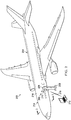
- inspection environment 200 is an example of one implementation for inspection environment 100 in Figure 1 .
- Backscatter inspection system 202 is configured to perform an inspection of aircraft 204 in inspection environment 200.
- Backscatter inspection system 202 is an example of one implementation for backscatter inspection system 102 in Figure 1 .
- backscatter inspection system 202 is a backscatter x-ray system.
- aircraft 204 is an example of one implementation for object 104 in Figure 1 .
- backscatter inspection system 202 includes moveable platform 206, radiation generation system 208, detector system 210, and computer system 212.
- Moveable platform 206, radiation generation system 208, detector system 210, and computer system 212 are examples of implementations for moveable platform 110, radiation generation system 112, detector system 114, and computer system 103, respectively, in Figure 1 .
- radiation generation system 208 and detector system 210 are connected to moveable platform 206.
- Computer system 212 is located away from moveable platform 206.
- Radiation generation system 208 is configured to generate x-rays and direct a portion of these x-rays towards fuselage 214 of aircraft 204 in the form of an x-ray beam.
- radiation generation system 208 directs the x-ray beam towards surface 216 of fuselage 214 of aircraft 204.
- Surface 216 is an exterior surface of fuselage 214.
- radiation generation system 208 may move the x-ray beam along surface 216 of fuselage 214 such that the angle of incidence of the x-ray beam with respect to surface 216 of fuselage 214 changes.
- the x-ray beam may at least partially penetrate surface 216 of fuselage 214 of aircraft 204.
- Detector system 210 is configured to detect backscatter formed in response to the x-ray beam encountering fuselage 214.
- Detector system 210 may generate image data that is sent to computer system 212 over wireless communications link 218.
- Detector system 210 is described in greater detail in Figures 3-4 .
- FIG. 3 an illustration of a cross-sectional view of an aircraft being inspected by a backscatter inspection system is depicted in accordance with an illustrative embodiment.
- a cross-sectional view of aircraft 204 from Figure 2 taken along lines 3-3, is depicted along with backscatter inspection system 202.
- Moveable platform 206 of backscatter inspection system 202 is not shown in this view such that radiation generation system 208 may be more clearly seen.
- radiation generation system 208 includes radiation source 300, housing 301, rotatable wheel 302, and motor 304.
- Radiation source 300 is an example of one implementation for radiation source 118 in Figure 1 . As depicted, radiation source 300 is located within housing 301. Housing 301 may be connected to moveable platform 206 in Figure 2 . Radiation source 300 is configured to generate and emit x-rays 306.
- Rotatable wheel 302 is associated with radiation source 300.
- Rotatable wheel 302 is an example of one implementation for rotatable wheel 128 in Figure 1 .
- Rotatable wheel 302 has number of apertures 308.
- Operation of motor 304 is configured to rotate rotatable wheel 302 such that number of apertures 308 rotate around radiation source 300.
- x-ray beam 310 is directed towards surface 216 of fuselage 214.
- the x-rays in x-ray beam 310 scatter in response to encountering fuselage 214. These scattered x-rays form backscatter 312.
- Detector system 210 detects backscatter 312. As depicted, detector system 210 has shape 314. Shape 314 is reconfigurable. In other words, shape 314 of detector system 210 may be changed.
- shape 314 is configured to substantially conform to surface shape 316 of surface 216 of fuselage 214.
- shape 314 is a convex shape with respect to radiation generation system 208 that is similar to surface shape 316 of surface 216 of fuselage 214, which is also a convex shape with respect to radiation generation system 208.
- detector system 210 includes number of sensor arrays 318 and structure 320.
- number of sensor arrays 318 includes sensor arrays 322, 324, 326, 328, and 330. These sensor arrays are associated with structure 320.
- the shape of structure 320 is shape 314 of detector system 210. In this manner, both detector system 210 and structure 320 have shape 314.
- Structure 320 comprises plurality of segments 332.
- Plurality of segments 332 includes segments 334, 336, 338, 340, and 342.
- Sensor arrays 322, 324, 326, 328, and 330 are associated with segments 334, 336, 338, 340, and 342, respectively.
- Segments 334, 336, 338, 340, and 342 may be connected to each other by flexible joints.
- segment 334 may be configured to move relative to segment 336 about a flexible joint connecting segment 334 and segment 336.
- sensor array 322 also moves relative to sensor array 324.
- One or more segments in plurality of segments 332 may be moved relative to each other such that structure 320 may have shape 314 that substantially conforms to surface shape 316 of surface 216 of fuselage 214.
- structure 320 may be bent at one or more of the flexible joints connecting plurality of segments 332 such that shape 314 of structure 320 changes to substantially conform to surface shape 316 of surface 216 of fuselage 214.
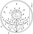
- FIG. 4 an illustration of a cross-sectional view of an aircraft being inspected by a backscatter inspection system is depicted in accordance with an illustrative embodiment.
- the cross-sectional view of aircraft 204 from Figure 3 is depicted with backscatter inspection system 202 moved into interior 400 of fuselage 214.
- radiation generation system 208 is configured to direct x-ray beam 310 towards surface 402 of fuselage 214.
- Surface 402 is an interior surface of fuselage 214.
- Backscatter 404 is formed in response to x-ray beam 310 encountering fuselage 214.
- shape 314 of detector system 210 has been changed such that shape 314 substantially conforms to surface shape 406 of surface 402 of fuselage 214.
- surface shape 406 of surface 402 has a concave shape with respect to radiation generation system 208.
- Structure 320 of detector system 210 has been bent at one or more flexible joints between plurality of segments 332 such that shape 314 of structure 320 has a concave shape with respect to radiation generation system 208 that is similar to the concave shape of surface 402 of fuselage 214.
- detector system 210 and radiation generation system 208 in backscatter inspection system 202 may be moved closer to surface 402.
- the amount of backscatter 404 detected by detector system 210 increases as detector system 210 moves closer to surface 402.
- detector system 500 is an example of one implementation for detector system 114 in Figure 1 .
- detector system 500 includes number of sensor arrays 502 associated with structure 504.
- Structure 504 takes the form of a deformable material in this example. Structure 504 is configured to be deformed such that structure 504 may have a desired shape. In this depicted example, structure 504 has wavy shape 506.
- sensor array 600 is an example of one sensor array in number of sensor arrays 502 in Figure 5 .
- sensor array 600 comprises number of sensors 602 arranged in two columns and three rows.
- Number of sensors 602 includes sensors 604, 606, 608, 610, 612, and 614.
- Each sensor in number of sensors 602 includes a scintillator and a light detector.
- sensor 604 includes scintillator 616 and light detector 618.
- light detector 618 is a micro-photomultiplier tube.
- light detector 618 may be some other suitable type of light detector.
- FIG. 7 an illustration of process for inspecting an object, in the form of a flowchart, is depicted in accordance with an illustrative embodiment.
- the process illustrated in Figure 7 may be used to inspect an object, such as object 104 in Figure 1 .
- This process may be implemented using, for example, without limitation, backscatter inspection system 102 in Figure 1 .
- the process begins by identifying a selected shape for a detector system in a backscatter inspection system (operation 700 ).
- the detector system may be detector system 114 in Figure 1 .
- the process then changes a shape of the detector system into the selected shape (operation 702 ).
- the shape of the detector system may be changed in a number of different ways using a structure in the detector system.
- the structure may be, for example, structure 144 in Figure 1 .
- Operation 702 may be performed by moving at least one of the segments in the plurality of segments relative to another segment in the plurality of segments about a flexible joint in the number of flexible joints.
- the process emits a beam towards a surface of an object (operation 704 ).
- the beam is formed using a portion of radiation emitted from a radiation source in the backscatter inspection system.
- the process detects backscatter formed in response to the beam encountering the object using the detector system having the selected shape (operation 706 ).
- the backscatter may be formed in response to at least a portion of the beam being scattered when the beam encounters the surface of the object and/or the subsurface of the object.
- the process generates image data in response to detecting the backscatter (operation 708 ).
- the process then forms an image of the object using the image data (operation 710 ).
- the process determines whether an inconsistency is present in the object using the image of the object (operation 712 ), with the process terminating thereafter.
- each block in the flowcharts or block diagrams may represent a module, segment, function, and/or a portion of an operation or step.
- one or more of the blocks may be implemented as program code, in hardware, or a combination of the program code and hardware.
- the hardware may, for example, take the form of integrated circuits that are manufactured or configured to perform one or more operations in the flowcharts or block diagrams.
- the function or functions noted in the blocks may occur out of the order noted in the figures.
- two blocks shown in succession may be executed substantially concurrently, or the blocks may sometimes be performed in the reverse order, depending upon the functionality involved.
- other blocks may be added in addition to the illustrated blocks in a flowchart or block diagram.
- an apparatus comprises a radiation source, a collimator, and a detector system.
- the radiation source is configured to emit radiation.
- the collimator is configured to form a beam using a portion of the radiation emitted by the radiation source.
- the beam is directed towards a surface of an object.
- the detector system is configured to detect backscatter formed in response to the beam encountering the object.
- a shape of the detector system is configured to be changed into a selected shape.
- the different illustrative embodiments provide a detector system that allows a smaller radiation source to be used in a backscatter inspection system. Further, with a detector system that has a shape that is reconfigurable, the size of the overall backscatter inspection system may be reduced. Still further, using light detectors based on micro-electromechanical systems technology in a detector system may reduce the cost of the detector system as compared to currently available detector systems.
Landscapes
- Chemical & Material Sciences (AREA)
- Crystallography & Structural Chemistry (AREA)
- Physics & Mathematics (AREA)
- Health & Medical Sciences (AREA)
- Life Sciences & Earth Sciences (AREA)
- Analytical Chemistry (AREA)
- Biochemistry (AREA)
- General Health & Medical Sciences (AREA)
- General Physics & Mathematics (AREA)
- Immunology (AREA)
- Pathology (AREA)
- Analysing Materials By The Use Of Radiation (AREA)
Claims (10)
- Vorrichtung, beinhaltend:eine Strahlungsquelle (118), die konfiguriert ist, Strahlung (122) auszustrahlen;einen Kollimator (120), der konfiguriert ist, einen Strahl (134) unter Verwendung eines Teils der Strahlung (122), die durch die Strahlungsquelle (118) ausgestrahlt wird, zu bilden, wobei der Strahl (134) zu einer Oberfläche (126) eines Objekts (104) gerichtet ist, wobei die Oberfläche des Objekts eine im Wesentlichen nicht ebene Oberflächenform vorsieht; undein Detektorsystem (114), das konfiguriert ist, eine Rückstreuung (136) zu erfassen, die als Reaktion darauf gebildet ist, dass der Strahl (134) auf das Objekt (104) trifft, in dem eine Form (138) des Detektorsystems (114) konfiguriert ist, im Wesentlichen der Oberflächenform des Objekts zu entsprechen, wobei die Form des Detektorsystems rekonfigurierbar ist, um einer anderen nicht ebenen Oberflächenform zu entsprechen,wobei das Detektorsystem (114) beinhaltet:eine Struktur (144), wobei die Form (138) des Detektorsystems (114) unter Verwendung der Struktur (144) rekonfigurierbar ist; undeine Zahl von Sensorarrays (142), die der Struktur (144) zugehörig sind, wobei die Zahl von Sensorarrays (142) konfiguriert ist, die Rückstreuung (136) zu erfassen, die als Reaktion darauf gebildet ist, dass der Strahl (134) auf das Objekt (104) trifft,wobei die Struktur (144) beinhaltet:mehrere Segmente (156), die durch eine Anzahl von flexiblen Gelenken (158) verbunden sind, wobei eine Bewegung von zumindest einem Segment in den mehreren Segmenten (156) relativ zu einem anderen Segment in den mehreren Segmenten (156) um ein flexibles Gelenk in der Anzahl von flexiblen Gelenken (158) die Form (138) des Detektorsystems (114) ändert.
- Vorrichtung nach Anspruch 1, wobei ein Sensorarray (146) in der Anzahl von Sensorarrays (142) beinhaltet:eine Anzahl von Sensoren (148), die in einer Anzahl von Reihen und einer Anzahl von Spalten angeordnet sind.
- Vorrichtung nach Anspruch 2, wobei ein Sensor (150) in der Anzahl von Sensoren (148) beinhaltet:einen Szintillator (152); undeinen Lichtdetektor (154).
- Vorrichtung nach Anspruch 2, wobei ein Sensor (150) in der Anzahl von Sensoren (148) einer von einem Szintillationsdetektor, einem Szintillationszähler, einem Festkörperdetektor und einem Halbleiterstrahlungsdetektor ist.
- Vorrichtung nach Anspruch 1, wobei die Oberflächenform des Objekts zumindest eine von einer konvexen Form, einer konkaven Form, einer welligen Form, einer gekrümmten Form, einer L-Form, einer U-Form und einer Ringform beinhaltet.
- Vorrichtung nach Anspruch 1, wobei die Strahlungsquelle (118) und der Kollimator (120) ein Strahlungserzeugungssystem (112) bilden und ferner beinhaltend:eine bewegliche Plattform (110), wobei zumindest eines des Strahlungserzeugungssystems (112) und des Detektorsystems (114) der beweglichen Plattform (110) zugehörig ist; undein Gehäuse (301), das mit der beweglichen Plattform (110) verbunden ist, wobei die Strahlungsquelle (118) innerhalb des Gehäuses (301) gelegen ist.
- Vorrichtung nach Anspruch 1, wobei der Kollimator (120) beinhaltet:ein drehbares Rad (128) mit einer Anzahl von Öffnungen (130), wobei das drehbare Rad (128) konfiguriert ist, sich zu drehen, während die Strahlungsquelle (118) die Strahlung (122) ausstrahlt, wobei der Teil der Strahlung (122), die durch die Strahlungsquelle (118) ausgestrahlt wird, durch eine Öffnung in der Anzahl von Öffnungen (130) hindurchgeht, um den Strahl (134) zu bilden.
- Vorrichtung nach Anspruch 1, wobei die Strahlungsquelle (118) eine Röntgenröhre ist, die Strahlung (122) Röntgenstrahlen (124) beinhaltet und der Strahl (134) ein Röntgenstrahl ist.
- Rückstreuungsröntgensystem, beinhaltend die Vorrichtung nach Anspruch 1, wobei:die Strahlungsquelle eine Röntgenröhre ist, die konfiguriert ist, Röntgenstrahlen (124) auszustrahlen; undder Kollimator (120) konfiguriert ist, unter Verwendung eines Teils der Röntgenstrahlen (124), die durch die Röntgenröhre ausgestrahlt werden, einen Röntgenstrahl zu bilden, wobei der Röntgenstrahl zu der Oberfläche (126) des Objekts (104) gerichtet ist.
- Rückstreuungsröntgensystem nach Anspruch 9, wobei ein Sensorarray (146) in der Anzahl von Sensorarrays (142) beinhaltet:eine Anzahl von Sensoren (148), wobei ein Sensor (150) in der Anzahl von Sensoren (148) beinhaltet:einen Szintillator (152); undeinen Lichtdetektor (154).
Applications Claiming Priority (2)
| Application Number | Priority Date | Filing Date | Title |
|---|---|---|---|
| US13/477,506 US8879688B2 (en) | 2012-05-22 | 2012-05-22 | Reconfigurable detector system |
| PCT/US2013/027173 WO2013176714A1 (en) | 2012-05-22 | 2013-02-21 | Reconfigurable detector system |
Publications (2)
| Publication Number | Publication Date |
|---|---|
| EP2852833A1 EP2852833A1 (de) | 2015-04-01 |
| EP2852833B1 true EP2852833B1 (de) | 2018-01-31 |
Family
ID=47844476
Family Applications (1)
| Application Number | Title | Priority Date | Filing Date |
|---|---|---|---|
| EP13708581.7A Active EP2852833B1 (de) | 2012-05-22 | 2013-02-21 | Rekonfigurierbares detektorsystem |
Country Status (5)
| Country | Link |
|---|---|
| US (1) | US8879688B2 (de) |
| EP (1) | EP2852833B1 (de) |
| JP (1) | JP6257599B2 (de) |
| CN (1) | CN104335031B (de) |
| WO (1) | WO2013176714A1 (de) |
Families Citing this family (24)
| Publication number | Priority date | Publication date | Assignee | Title |
|---|---|---|---|---|
| US9594033B2 (en) * | 2014-07-22 | 2017-03-14 | The Boeing Company | Visible X-ray indication and detection system for X-ray backscatter applications |
| WO2016123688A1 (en) * | 2015-02-06 | 2016-08-11 | Teledyne Dalsa, Inc. | Articulated segmented x-ray detector system and method |
| US9689813B2 (en) * | 2015-02-27 | 2017-06-27 | The Boeing Company | Detecting gaps between fasteners and openings |
| US9989483B2 (en) * | 2015-08-17 | 2018-06-05 | The Boeing Company | Systems and methods for performing backscatter three dimensional imaging from one side of a structure |
| US10317349B2 (en) | 2015-11-30 | 2019-06-11 | The Boeing Company | X-ray scatter systems and methods for detecting structural variations |
| US10483316B2 (en) * | 2016-01-13 | 2019-11-19 | mPower Technology, Inc. | Fabrication and operation of multi-function flexible radiation detection systems |
| US10191014B2 (en) * | 2016-08-23 | 2019-01-29 | The Boeing Company | System and method for nondestructive evaluation of a test object |
| US10541102B2 (en) * | 2016-09-14 | 2020-01-21 | The Boeing Company | X-ray back scattering for inspection of part |
| CN106290427A (zh) * | 2016-10-17 | 2017-01-04 | 北京君和信达科技有限公司 | 背散射成像方法及系统 |
| KR102550104B1 (ko) | 2016-12-09 | 2023-06-30 | 엠파워 테크놀로지 인코포레이티드 | 고성능 태양 전지, 이의 어레이 및 제조 방법 |
| PL3425377T3 (pl) * | 2017-07-05 | 2022-09-19 | Rigaku Corporation | Detektor promieniowania rentgenowskiego i technika sterowania detektorem promieniowania rentgenowskiego |
| CN108008458B (zh) * | 2017-12-29 | 2020-09-08 | 同方威视技术股份有限公司 | 车载背散射检查系统 |
| CN108227027B (zh) * | 2017-12-29 | 2020-12-01 | 同方威视技术股份有限公司 | 车载背散射检查系统 |
| US10914848B1 (en) | 2018-07-13 | 2021-02-09 | mPower Technology, Inc. | Fabrication, integration and operation of multi-function radiation detection systems |
| US12009451B2 (en) | 2018-07-30 | 2024-06-11 | mPower Technology, Inc. | In-situ rapid annealing and operation of solar cells for extreme environment applications |
| US10859719B2 (en) * | 2018-12-13 | 2020-12-08 | The Boeing Company | Adjustable multifacet x-ray sensor array |
| US11112370B2 (en) | 2019-01-04 | 2021-09-07 | The Boeing Company | Reconfigurable backscatter detector |
| US11375963B2 (en) | 2019-04-10 | 2022-07-05 | Argospect Technologies Inc. | Medical imaging systems and methods of using the same |
| US11119058B2 (en) * | 2019-05-22 | 2021-09-14 | The Boeing Company | Non-destructive inspection methods, systems and apparatuses using focusable x-ray backscatter detectors |
| US10830714B1 (en) * | 2019-07-26 | 2020-11-10 | The Boeing Company | Portable X-ray backscattering system |
| WO2021025898A1 (en) * | 2019-08-02 | 2021-02-11 | Videray Technologies, Inc. | Enclosed x-ray chopper wheel |
| IT202100026417A1 (it) * | 2021-10-14 | 2023-04-14 | Milano Politecnico | Dispositivo e sistema di rivelazione di radiazioni emesse da un campione irraggiato con un fascio di eccitazione |
| US12392736B2 (en) | 2023-03-01 | 2025-08-19 | The Boeing Company | Method and system for inspecting and measuring installed one-sided fasteners in a structure |
| WO2024228921A2 (en) | 2023-04-29 | 2024-11-07 | Videray Technologies, Inc. | Handheld x-ray system including a stand-alone detector panel |
Family Cites Families (29)
| Publication number | Priority date | Publication date | Assignee | Title |
|---|---|---|---|---|
| JPS53138778A (en) * | 1977-05-11 | 1978-12-04 | Hitachi Ltd | Stress measuring device by x-ray |
| US6243441B1 (en) | 1999-07-13 | 2001-06-05 | Edge Medical Devices | Active matrix detector for X-ray imaging |
| JP3766793B2 (ja) * | 2001-10-25 | 2006-04-19 | 株式会社日立ハイテクノロジーズ | 走査電子顕微鏡 |
| US7078702B2 (en) * | 2002-07-25 | 2006-07-18 | General Electric Company | Imager |
| US7099434B2 (en) * | 2002-11-06 | 2006-08-29 | American Science And Engineering, Inc. | X-ray backscatter mobile inspection van |
| US7400701B1 (en) * | 2004-04-09 | 2008-07-15 | American Science And Engineering, Inc. | Backscatter inspection portal |
| GB0411403D0 (en) * | 2004-05-21 | 2004-06-23 | Tissuomics Ltd | Irradiating body tissue |
| GB0411401D0 (en) * | 2004-05-21 | 2004-06-23 | Tissuomics Ltd | Penetrating radiation measurements |
| US7224772B2 (en) | 2004-07-20 | 2007-05-29 | University Of Florida Research Foundation, Inc. | Radiography by selective detection of scatter field velocity components |
| BRPI0513738A (pt) * | 2004-07-23 | 2008-05-13 | Electric Power Res Inst | sensor transdutor acústico eletromagnético flexìvel |
| JP4156572B2 (ja) * | 2004-07-28 | 2008-09-24 | アンリツ産機システム株式会社 | 物品検査装置 |
| US7249512B2 (en) | 2005-01-24 | 2007-07-31 | The Boeing Company | Non-destructive stringer inspection apparatus and method |
| WO2006102274A1 (en) * | 2005-03-21 | 2006-09-28 | American Science And Engineering, Inc. | Increased detectability and range for x-ray backscatter imaging systems |
| US7130374B1 (en) | 2005-05-11 | 2006-10-31 | University Of Florida Research Foundation, Inc. | Snapshot backscatter radiography (SBR) systems including system having dynamic collimation |
| JP4669768B2 (ja) | 2005-09-30 | 2011-04-13 | 富士フイルム株式会社 | 解像度可変型x線撮像装置及びx線ct装置 |
| WO2007051092A2 (en) * | 2005-10-24 | 2007-05-03 | American Science And Engineering, Inc. | X-ray inspection based on scatter detection |
| US7649976B2 (en) | 2006-02-10 | 2010-01-19 | The Boeing Company | System and method for determining dimensions of structures/systems for designing modifications to the structures/systems |
| US7529343B2 (en) | 2006-05-04 | 2009-05-05 | The Boeing Company | System and method for improved field of view X-ray imaging using a non-stationary anode |
| US7508910B2 (en) | 2006-05-04 | 2009-03-24 | The Boeing Company | System and methods for x-ray backscatter reverse engineering of structures |
| EP2076793B1 (de) * | 2006-10-24 | 2016-01-06 | Thermo Scientific Portable Analytical Instruments Inc. | Vorrichtung zum untersuchen von objekten unter verwendung eines kodierten strahls |
| US7535990B2 (en) | 2006-12-22 | 2009-05-19 | The Boeing Company | Low profile vision system for remote x-ray inspection |
| JP2011516838A (ja) * | 2008-03-31 | 2011-05-26 | サザン イノヴェーション インターナショナル プロプライアトリー リミテッド | スクリーニング方法および装置 |
| US7567649B1 (en) | 2008-06-25 | 2009-07-28 | The Boeing Company | Flexible detector for x-ray applications |
| EP2146226A1 (de) * | 2008-07-14 | 2010-01-20 | ICx Technologies GmbH | Detektorsystem zur Strahlungsmessung |
| US8033724B2 (en) | 2009-06-30 | 2011-10-11 | The Boeing Company | Rapid assembly and operation of an X-ray imaging system |
| WO2011011583A1 (en) * | 2009-07-24 | 2011-01-27 | Nucsafe, Inc. | Spatial sequenced backscatter portal |
| US8824632B2 (en) | 2009-07-29 | 2014-09-02 | American Science And Engineering, Inc. | Backscatter X-ray inspection van with top-down imaging |
| CN102313753B (zh) * | 2010-06-30 | 2014-07-16 | 清华大学 | 物品检测设备及其检测方法 |
| MY182655A (en) | 2011-04-15 | 2021-01-28 | American Science & Eng Inc | Backscatter system with variable size of detector array |
-
2012
- 2012-05-22 US US13/477,506 patent/US8879688B2/en active Active
-
2013
- 2013-02-21 JP JP2015513998A patent/JP6257599B2/ja active Active
- 2013-02-21 WO PCT/US2013/027173 patent/WO2013176714A1/en not_active Ceased
- 2013-02-21 EP EP13708581.7A patent/EP2852833B1/de active Active
- 2013-02-21 CN CN201380024627.4A patent/CN104335031B/zh active Active
Also Published As
| Publication number | Publication date |
|---|---|
| JP2015517672A (ja) | 2015-06-22 |
| US8879688B2 (en) | 2014-11-04 |
| EP2852833A1 (de) | 2015-04-01 |
| CN104335031B (zh) | 2017-09-08 |
| WO2013176714A1 (en) | 2013-11-28 |
| US20130315376A1 (en) | 2013-11-28 |
| JP6257599B2 (ja) | 2018-01-10 |
| CN104335031A (zh) | 2015-02-04 |
Similar Documents
| Publication | Publication Date | Title |
|---|---|---|
| US8879688B2 (en) | Reconfigurable detector system | |
| JP2015517672A5 (de) | ||
| US9123450B2 (en) | Single beam backscatter x-ray system | |
| ES2718884T3 (es) | Sistema de tomografía computarizada para carga y contenedores transportados | |
| JP6465867B2 (ja) | ミューオン検出アレイステーション | |
| US9658173B2 (en) | Portable x-ray backscattering imaging system including a radioactive source | |
| EP2993495B1 (de) | Fahrzeugmontiertes inspektionssystem | |
| EP2538206B1 (de) | Integriertes Rückstreuungs-Röntgenstrahlsystem | |
| US10024981B2 (en) | System and method for locating radiation sources | |
| US8853634B2 (en) | Resin detection system | |
| US8503610B1 (en) | X-ray inspection tool | |
| US20180321399A1 (en) | Gamma Ray Detector with Two-Dimensional Directionality | |
| US12270770B2 (en) | Systems and methods for monitoring feature sizes in digital X-ray imaging | |
| US10874364B2 (en) | Apparatus and method for three-dimensional inspection of an object by x-rays | |
| US11112370B2 (en) | Reconfigurable backscatter detector | |
| EP3770590A2 (de) | Tragbares röntgenrückstreuungssystem | |
| US8306179B2 (en) | Reconstruction of linearly moving objects with intermitten X-ray sources | |
| WO2023009793A1 (en) | Systems and methods for monitoring feature sizes in digital x-ray imaging | |
| WO2006134362A2 (en) | X-ray screening apparatus with independently moveable source and detector |
Legal Events
| Date | Code | Title | Description |
|---|---|---|---|
| PUAI | Public reference made under article 153(3) epc to a published international application that has entered the european phase |
Free format text: ORIGINAL CODE: 0009012 |
|
| 17P | Request for examination filed |
Effective date: 20141126 |
|
| AK | Designated contracting states |
Kind code of ref document: A1 Designated state(s): AL AT BE BG CH CY CZ DE DK EE ES FI FR GB GR HR HU IE IS IT LI LT LU LV MC MK MT NL NO PL PT RO RS SE SI SK SM TR |
|
| AX | Request for extension of the european patent |
Extension state: BA ME |
|
| DAX | Request for extension of the european patent (deleted) | ||
| 17Q | First examination report despatched |
Effective date: 20170125 |
|
| GRAP | Despatch of communication of intention to grant a patent |
Free format text: ORIGINAL CODE: EPIDOSNIGR1 |
|
| INTG | Intention to grant announced |
Effective date: 20170721 |
|
| GRAS | Grant fee paid |
Free format text: ORIGINAL CODE: EPIDOSNIGR3 |
|
| GRAA | (expected) grant |
Free format text: ORIGINAL CODE: 0009210 |
|
| AK | Designated contracting states |
Kind code of ref document: B1 Designated state(s): AL AT BE BG CH CY CZ DE DK EE ES FI FR GB GR HR HU IE IS IT LI LT LU LV MC MK MT NL NO PL PT RO RS SE SI SK SM TR |
|
| REG | Reference to a national code |
Ref country code: GB Ref legal event code: FG4D Ref country code: CH Ref legal event code: EP |
|
| REG | Reference to a national code |
Ref country code: AT Ref legal event code: REF Ref document number: 967837 Country of ref document: AT Kind code of ref document: T Effective date: 20180215 |
|
| REG | Reference to a national code |
Ref country code: IE Ref legal event code: FG4D |
|
| REG | Reference to a national code |
Ref country code: FR Ref legal event code: PLFP Year of fee payment: 6 |
|
| REG | Reference to a national code |
Ref country code: DE Ref legal event code: R096 Ref document number: 602013032559 Country of ref document: DE |
|
| REG | Reference to a national code |
Ref country code: NL Ref legal event code: MP Effective date: 20180131 |
|
| REG | Reference to a national code |
Ref country code: LT Ref legal event code: MG4D |
|
| REG | Reference to a national code |
Ref country code: AT Ref legal event code: MK05 Ref document number: 967837 Country of ref document: AT Kind code of ref document: T Effective date: 20180131 |
|
| PG25 | Lapsed in a contracting state [announced via postgrant information from national office to epo] |
Ref country code: LT Free format text: LAPSE BECAUSE OF FAILURE TO SUBMIT A TRANSLATION OF THE DESCRIPTION OR TO PAY THE FEE WITHIN THE PRESCRIBED TIME-LIMIT Effective date: 20180131 Ref country code: NL Free format text: LAPSE BECAUSE OF FAILURE TO SUBMIT A TRANSLATION OF THE DESCRIPTION OR TO PAY THE FEE WITHIN THE PRESCRIBED TIME-LIMIT Effective date: 20180131 Ref country code: FI Free format text: LAPSE BECAUSE OF FAILURE TO SUBMIT A TRANSLATION OF THE DESCRIPTION OR TO PAY THE FEE WITHIN THE PRESCRIBED TIME-LIMIT Effective date: 20180131 Ref country code: HR Free format text: LAPSE BECAUSE OF FAILURE TO SUBMIT A TRANSLATION OF THE DESCRIPTION OR TO PAY THE FEE WITHIN THE PRESCRIBED TIME-LIMIT Effective date: 20180131 Ref country code: NO Free format text: LAPSE BECAUSE OF FAILURE TO SUBMIT A TRANSLATION OF THE DESCRIPTION OR TO PAY THE FEE WITHIN THE PRESCRIBED TIME-LIMIT Effective date: 20180430 Ref country code: ES Free format text: LAPSE BECAUSE OF FAILURE TO SUBMIT A TRANSLATION OF THE DESCRIPTION OR TO PAY THE FEE WITHIN THE PRESCRIBED TIME-LIMIT Effective date: 20180131 |
|
| PG25 | Lapsed in a contracting state [announced via postgrant information from national office to epo] |
Ref country code: RS Free format text: LAPSE BECAUSE OF FAILURE TO SUBMIT A TRANSLATION OF THE DESCRIPTION OR TO PAY THE FEE WITHIN THE PRESCRIBED TIME-LIMIT Effective date: 20180131 Ref country code: PL Free format text: LAPSE BECAUSE OF FAILURE TO SUBMIT A TRANSLATION OF THE DESCRIPTION OR TO PAY THE FEE WITHIN THE PRESCRIBED TIME-LIMIT Effective date: 20180131 Ref country code: GR Free format text: LAPSE BECAUSE OF FAILURE TO SUBMIT A TRANSLATION OF THE DESCRIPTION OR TO PAY THE FEE WITHIN THE PRESCRIBED TIME-LIMIT Effective date: 20180501 Ref country code: SE Free format text: LAPSE BECAUSE OF FAILURE TO SUBMIT A TRANSLATION OF THE DESCRIPTION OR TO PAY THE FEE WITHIN THE PRESCRIBED TIME-LIMIT Effective date: 20180131 Ref country code: LV Free format text: LAPSE BECAUSE OF FAILURE TO SUBMIT A TRANSLATION OF THE DESCRIPTION OR TO PAY THE FEE WITHIN THE PRESCRIBED TIME-LIMIT Effective date: 20180131 Ref country code: BG Free format text: LAPSE BECAUSE OF FAILURE TO SUBMIT A TRANSLATION OF THE DESCRIPTION OR TO PAY THE FEE WITHIN THE PRESCRIBED TIME-LIMIT Effective date: 20180430 Ref country code: IS Free format text: LAPSE BECAUSE OF FAILURE TO SUBMIT A TRANSLATION OF THE DESCRIPTION OR TO PAY THE FEE WITHIN THE PRESCRIBED TIME-LIMIT Effective date: 20180531 Ref country code: AT Free format text: LAPSE BECAUSE OF FAILURE TO SUBMIT A TRANSLATION OF THE DESCRIPTION OR TO PAY THE FEE WITHIN THE PRESCRIBED TIME-LIMIT Effective date: 20180131 |
|
| REG | Reference to a national code |
Ref country code: CH Ref legal event code: PL |
|
| PG25 | Lapsed in a contracting state [announced via postgrant information from national office to epo] |
Ref country code: AL Free format text: LAPSE BECAUSE OF FAILURE TO SUBMIT A TRANSLATION OF THE DESCRIPTION OR TO PAY THE FEE WITHIN THE PRESCRIBED TIME-LIMIT Effective date: 20180131 Ref country code: IT Free format text: LAPSE BECAUSE OF FAILURE TO SUBMIT A TRANSLATION OF THE DESCRIPTION OR TO PAY THE FEE WITHIN THE PRESCRIBED TIME-LIMIT Effective date: 20180131 Ref country code: EE Free format text: LAPSE BECAUSE OF FAILURE TO SUBMIT A TRANSLATION OF THE DESCRIPTION OR TO PAY THE FEE WITHIN THE PRESCRIBED TIME-LIMIT Effective date: 20180131 Ref country code: RO Free format text: LAPSE BECAUSE OF FAILURE TO SUBMIT A TRANSLATION OF THE DESCRIPTION OR TO PAY THE FEE WITHIN THE PRESCRIBED TIME-LIMIT Effective date: 20180131 |
|
| REG | Reference to a national code |
Ref country code: DE Ref legal event code: R097 Ref document number: 602013032559 Country of ref document: DE |
|
| REG | Reference to a national code |
Ref country code: IE Ref legal event code: MM4A |
|
| REG | Reference to a national code |
Ref country code: BE Ref legal event code: MM Effective date: 20180228 |
|
| PG25 | Lapsed in a contracting state [announced via postgrant information from national office to epo] |
Ref country code: SK Free format text: LAPSE BECAUSE OF FAILURE TO SUBMIT A TRANSLATION OF THE DESCRIPTION OR TO PAY THE FEE WITHIN THE PRESCRIBED TIME-LIMIT Effective date: 20180131 Ref country code: LU Free format text: LAPSE BECAUSE OF NON-PAYMENT OF DUE FEES Effective date: 20180221 Ref country code: CH Free format text: LAPSE BECAUSE OF NON-PAYMENT OF DUE FEES Effective date: 20180228 Ref country code: CZ Free format text: LAPSE BECAUSE OF FAILURE TO SUBMIT A TRANSLATION OF THE DESCRIPTION OR TO PAY THE FEE WITHIN THE PRESCRIBED TIME-LIMIT Effective date: 20180131 Ref country code: LI Free format text: LAPSE BECAUSE OF NON-PAYMENT OF DUE FEES Effective date: 20180228 Ref country code: MC Free format text: LAPSE BECAUSE OF FAILURE TO SUBMIT A TRANSLATION OF THE DESCRIPTION OR TO PAY THE FEE WITHIN THE PRESCRIBED TIME-LIMIT Effective date: 20180131 Ref country code: SM Free format text: LAPSE BECAUSE OF FAILURE TO SUBMIT A TRANSLATION OF THE DESCRIPTION OR TO PAY THE FEE WITHIN THE PRESCRIBED TIME-LIMIT Effective date: 20180131 Ref country code: DK Free format text: LAPSE BECAUSE OF FAILURE TO SUBMIT A TRANSLATION OF THE DESCRIPTION OR TO PAY THE FEE WITHIN THE PRESCRIBED TIME-LIMIT Effective date: 20180131 |
|
| PLBE | No opposition filed within time limit |
Free format text: ORIGINAL CODE: 0009261 |
|
| STAA | Information on the status of an ep patent application or granted ep patent |
Free format text: STATUS: NO OPPOSITION FILED WITHIN TIME LIMIT |
|
| 26N | No opposition filed |
Effective date: 20181102 |
|
| PG25 | Lapsed in a contracting state [announced via postgrant information from national office to epo] |
Ref country code: IE Free format text: LAPSE BECAUSE OF NON-PAYMENT OF DUE FEES Effective date: 20180221 |
|
| PG25 | Lapsed in a contracting state [announced via postgrant information from national office to epo] |
Ref country code: SI Free format text: LAPSE BECAUSE OF FAILURE TO SUBMIT A TRANSLATION OF THE DESCRIPTION OR TO PAY THE FEE WITHIN THE PRESCRIBED TIME-LIMIT Effective date: 20180131 Ref country code: BE Free format text: LAPSE BECAUSE OF NON-PAYMENT OF DUE FEES Effective date: 20180228 |
|
| PG25 | Lapsed in a contracting state [announced via postgrant information from national office to epo] |
Ref country code: MT Free format text: LAPSE BECAUSE OF NON-PAYMENT OF DUE FEES Effective date: 20180221 |
|
| PG25 | Lapsed in a contracting state [announced via postgrant information from national office to epo] |
Ref country code: TR Free format text: LAPSE BECAUSE OF FAILURE TO SUBMIT A TRANSLATION OF THE DESCRIPTION OR TO PAY THE FEE WITHIN THE PRESCRIBED TIME-LIMIT Effective date: 20180131 |
|
| PG25 | Lapsed in a contracting state [announced via postgrant information from national office to epo] |
Ref country code: PT Free format text: LAPSE BECAUSE OF FAILURE TO SUBMIT A TRANSLATION OF THE DESCRIPTION OR TO PAY THE FEE WITHIN THE PRESCRIBED TIME-LIMIT Effective date: 20180131 |
|
| PG25 | Lapsed in a contracting state [announced via postgrant information from national office to epo] |
Ref country code: MK Free format text: LAPSE BECAUSE OF NON-PAYMENT OF DUE FEES Effective date: 20180131 Ref country code: CY Free format text: LAPSE BECAUSE OF FAILURE TO SUBMIT A TRANSLATION OF THE DESCRIPTION OR TO PAY THE FEE WITHIN THE PRESCRIBED TIME-LIMIT Effective date: 20180131 Ref country code: HU Free format text: LAPSE BECAUSE OF FAILURE TO SUBMIT A TRANSLATION OF THE DESCRIPTION OR TO PAY THE FEE WITHIN THE PRESCRIBED TIME-LIMIT; INVALID AB INITIO Effective date: 20130221 |
|
| P01 | Opt-out of the competence of the unified patent court (upc) registered |
Effective date: 20230516 |
|
| PGFP | Annual fee paid to national office [announced via postgrant information from national office to epo] |
Ref country code: GB Payment date: 20260227 Year of fee payment: 14 |
|
| PGFP | Annual fee paid to national office [announced via postgrant information from national office to epo] |
Ref country code: DE Payment date: 20260227 Year of fee payment: 14 |
|
| PGFP | Annual fee paid to national office [announced via postgrant information from national office to epo] |
Ref country code: FR Payment date: 20260225 Year of fee payment: 14 |