EP2852016A2 - Electric/electronic installation device - Google Patents
Electric/electronic installation device Download PDFInfo
- Publication number
- EP2852016A2 EP2852016A2 EP20140165106 EP14165106A EP2852016A2 EP 2852016 A2 EP2852016 A2 EP 2852016A2 EP 20140165106 EP20140165106 EP 20140165106 EP 14165106 A EP14165106 A EP 14165106A EP 2852016 A2 EP2852016 A2 EP 2852016A2
- Authority
- EP
- European Patent Office
- Prior art keywords
- electrical
- electronic installation
- installation device
- locking means
- latching
- Prior art date
- Legal status (The legal status is an assumption and is not a legal conclusion. Google has not performed a legal analysis and makes no representation as to the accuracy of the status listed.)
- Granted
Links
Images


Classifications
-
- H—ELECTRICITY
- H02—GENERATION; CONVERSION OR DISTRIBUTION OF ELECTRIC POWER
- H02G—INSTALLATION OF ELECTRIC CABLES OR LINES, OR OF COMBINED OPTICAL AND ELECTRIC CABLES OR LINES
- H02G3/00—Installations of electric cables or lines or protective tubing therefor in or on buildings, equivalent structures or vehicles
- H02G3/02—Details
- H02G3/08—Distribution boxes; Connection or junction boxes
- H02G3/12—Distribution boxes; Connection or junction boxes for flush mounting
- H02G3/121—Distribution boxes; Connection or junction boxes for flush mounting in plain walls
-
- H—ELECTRICITY
- H02—GENERATION; CONVERSION OR DISTRIBUTION OF ELECTRIC POWER
- H02G—INSTALLATION OF ELECTRIC CABLES OR LINES, OR OF COMBINED OPTICAL AND ELECTRIC CABLES OR LINES
- H02G3/00—Installations of electric cables or lines or protective tubing therefor in or on buildings, equivalent structures or vehicles
- H02G3/02—Details
- H02G3/08—Distribution boxes; Connection or junction boxes
- H02G3/086—Assembled boxes
Definitions
- the present invention is based on a designed according to the preamble of the main claim electrical / electronic installation device.
- Such electrical / electronic installation devices are often designed as switching devices or as a screen-mounted control units and usually intended to effect the switching on and off of circuits or the switching of circuits optionally via a bus system. If necessary, various information can also be displayed via such electrical / electronic installation devices.
- electrical / electronic installation devices are often designed as so-called door communication devices and provided for the operation of the bell or door intercom of a building. If required, such door communication devices can also be equipped with a camera system.
- the operation of such electrical / electronic installation devices can be done for example by adjusting an example as a button, rocker, etc. formed actuator, the functional positions can be performed, for example, groping. For operation, a so-called touch screen can also be used.
- An according to the preamble of the main claim corresponding electrical / electronic installation device is through the DE 10 2010 016 345 B4 known.
- This designed as a control unit for a building installation system electrical / electronic installation device is for a again removable mounting provided in a built-in housing, which is fixedly installed in a wall of a building.
- the electrical / electronic installation device has a functional module that can be fixed to a carrier arrangement, wherein a design cover can also be fixed to the carrier arrangement, and wherein the carrier arrangement is provided for fixing in the installation housing.
- the carrier assembly is relatively complex and also the handling for installation or removal is relatively expensive.
- the present invention is therefore an object of the invention to provide an electrical / electronic installation device, which is particularly simple and comfortable to handle with regard to the determination in and removal from the associated installation housing with automatic plaster compensation.
- a first latching means in the manner of a window-like opening and a second latching means are designed in the manner of a detent spring, because so find particularly simple design and inexpensive to manufacture and to be assembled components use.
- the electrical / electronic installation device is provided for removable mounting in a mounting housing 1.
- the installation housing 1 is in turn provided for stationary installation in or on (indoor or outdoor) buildings.
- the electrical / electronic installation device has a plurality of functional modules 3, 4 which can be fixed to a carrier arrangement 2, wherein a design cover 5 can also be fixed to the carrier arrangement 2.
- the carrier assembly 2 is provided for fixing in the installation housing 1.
- a compensating insert A is present in the housing 1, which is held in its installation depth adjustable in the housing 1.
- the compensation insert A is thus functionally attributable to the installation housing 1.
- the compensating insert A has two first locking means 9, which cooperate latching with in each case an associated second locking means 8, which are each mounted on the support assembly 2.
- a first locking means 9 are each carried out in the manner of a window-like opening and introduced into two side walls, which are arranged opposite to each other.
- the two existing on the carrier assembly 2 second locking means 8 are each carried out in the manner of a detent spring.
- Each of the two second locking means 8 has two locking legs 8a, which in each case with a own operating base 6 are provided.
- the first locking means 9 and the second locking means 8 are arranged concealed by the design cover 5.
- each of the two attached to the carrier assembly 2 second locking means 8 (detent spring), a, between the two locking legs 8a arranged holding leg 7.
- the two second locking means 8 (detent springs) are thus fixed in exact position on the carrier assembly 2.
- the latching leg 8a and the first latching means 9 designed as window-like openings are dimensionally matched to one another or designed in such a way that during the assembly of the electrical / electronic installation device in the installation housing 1 or compensating insert A a guidance in the vertical direction is ensured.
- the installation housing 1 is designed in the manner of a rectangular box and the balance insert A has a frame-like design and comes with its outer walls on the inner walls of the mounting housing 1 to the plant.
- the balance insert A has four extending in the mounting direction slots S, which cooperate with mounting screws B of the mounting housing 1. After plastering of the installation housing 1 can thus be made automatically in a simple manner, the compensation by the compensating insert A is inserted as far into the housing 1, until this with its overhanging edge region R on the Wall W comes to the plant. Subsequently, the balance insert A is fixed positionally secure by tightening the mounting screws B in the housing 1.
- each of the two second locking means 8 (detent springs) - as already described - two resiliently executed locking legs 8a, which latching with the associated first locking means 9 (window-like Openings) interact, which are introduced into the balance insert A.
- the four locking legs 8a are under bias by spring detent in its fixing position. The insertion or the taking of the fixing position is carried out simply by an indenting movement, with which the carrier assembly 2 can be fixed even without a pivoting action on the housing 1 and in the compensation insert A.
- the two locking legs 8a of one of the two second locking means 8 are actuated by an unlocking tool 10, wherein the unlocking tool 10 cooperates respectively with the actuating base 6 of the two associated locking legs 8a.
- the two locking legs 8a are released by the unlocking tool 10 designed as Entriegelungsblech from its latching with the two associated first locking means 9 of the balance insert A and brought into their removal position.
- the installation housing 1 is provided for flush mounting, which is why an automatic plaster compensation is of particular advantage.
- the electrical / electronic installation device is designed as a door communication device.
- the electrical / electronic installation device can be assigned to the exterior or the interior of an entrance door, so be installed near the entrance door in the associated wall W of the building.
- the design cover 5 is provided at its, the wall W associated rear with an elastic seal D.
- the first functional module 3 has four actuating keys and is provided for activating the associated doorbell in each case in accordance with the requirements.
- the second functional module 4 contains a substantial part of the functional components of the door intercom, so it is usually equipped with a loudspeaker, microphone, electrical / electronic control components and so on. To complicate the possibility of actuating the second locking means 8 (detent springs) for unauthorized persons, they are covered by the design cover 5.
- a strap-like holding arrangement 12 is attached to the support assembly 2, which on the one hand serves to attach a tether, which on the other hand is fixed to the housing 1, whereby a secure holding possibility for removed from the housing 1 electrical / electronic installation device is realized.
- the tether is not shown.
Landscapes
- Engineering & Computer Science (AREA)
- Architecture (AREA)
- Civil Engineering (AREA)
- Structural Engineering (AREA)
- Casings For Electric Apparatus (AREA)
Abstract
Es wird ein elektrisches/elektronisches Installationsgerät vorgeschlagen, welches zur wieder entnehmbaren Montage in einem Einbaugehäuse vorgesehen ist, wobei das Einbaugehäuse ortsfest in oder an einem Gebäude angebracht ist, wobei das elektrische/elektronische Installationsgerät zumindest ein an einer Trägeranordnung festlegbares Funktionsmodul aufweist, wobei an der Trägeranordnung eine Designabdeckung festlegbar ist und wobei die Trägeranordnung zur Festlegung in dem Einbaugehäuse vorgesehen ist. Zu dem Zweck, ein elektrisches/elektronisches Installationsgerät zu schaffen, welches hinsichtlich der Festlegung in und der Entnahme aus dem zugehörigen Einbaugehäuse bei automatischem Putzausgleich besonders einfach und komfortabel zu handhaben ist, ist im Einbaugehäuse zumindest ein, in seiner Einbautiefe verstellbarer Ausgleichseinsatz gehalten, wobei der Ausgleichseinsatz zumindest ein erstes Rastmittel aufweist, welches verrastend mit einem zweiten Rastmittel zusammenwirkt, welches an der Trägeranordnung vorhanden ist.It is proposed an electrical / electronic installation device, which is provided for removable mounting in a mounting housing, wherein the mounting housing is fixedly mounted in or on a building, wherein the electrical / electronic installation device has at least one fixable on a carrier assembly function module, wherein the Carrier assembly is a design cover can be fixed and wherein the support assembly is provided for fixing in the mounting housing. For the purpose of creating an electrical / electronic installation device, which is particularly simple and comfortable to handle with regard to the determination in and removal from the associated installation housing with automatic plaster compensation, is held in the housing at least one, adjustable in its depth compensation insert, wherein the Balancing insert has at least a first locking means which cooperating latching with a second locking means which is provided on the carrier assembly.
Description
Die vorliegende Erfindung geht von einem gemäß Oberbegriff des Hauptanspruches konzipierten elektrischen/elektronischen Installationsgerät aus.The present invention is based on a designed according to the preamble of the main claim electrical / electronic installation device.
Derartige elektrische/elektronische Installationsgeräte sind oftmals als Schaltgeräte oder als bildschirmgeführte Steuergeräte ausgeführt und in der Regel dafür vorgesehen, die Ein- und Ausschaltung von Stromkreisen bzw. die Umschaltung von Stromkreisen gegebenenfalls über ein Bussystem zu bewirken. Über solche elektrische/elektronische Installationsgeräte können gegebenenfalls auch verschiedene Informationen zur Anzeige gebracht werden. Außerdem sind solche elektrischen/elektronischen Installationsgeräte oftmals auch als sogenannte Türkommunikationsgeräte ausgeführt und zur Bedienung der Klingel bzw. Türsprechanlage eines Gebäudes vorgesehen. Solche Türkommunikationsgeräte können bei Bedarf auch mit einer Kameraanlage ausgerüstet sein. Die Betätigung solcher elektrischer/elektronischer Installationsgeräte kann zum Beispiel durch das Verstellen eines beispielsweise als Taste, Wippe usw. ausgebildeten Betätigungsgliedes erfolgen, wobei die Funktionsstellungen zum Beispiel tastend ausgeführt sein können. Zur Betätigung kann auch ein sogenannter Touchscreen Verwendung finden. Oftmals sind solche elektrischen/elektronischen Installationsgeräte zur Installation in Installationsdosen oder in Einbaugehäusen vorgesehen, wobei die zur Verwendung kommenden Befestigungsvorrichtungen, wie zum Beispiel Spreizkrallen, Schraubverbindungen usw. dafür vorgesehen sind, eine einfache Festlegung und bei Bedarf eine einfache Entnahme solcher elektrischer/elektronischer Installationsgeräte zu ermöglichen.Such electrical / electronic installation devices are often designed as switching devices or as a screen-mounted control units and usually intended to effect the switching on and off of circuits or the switching of circuits optionally via a bus system. If necessary, various information can also be displayed via such electrical / electronic installation devices. In addition, such electrical / electronic installation devices are often designed as so-called door communication devices and provided for the operation of the bell or door intercom of a building. If required, such door communication devices can also be equipped with a camera system. The operation of such electrical / electronic installation devices can be done for example by adjusting an example as a button, rocker, etc. formed actuator, the functional positions can be performed, for example, groping. For operation, a so-called touch screen can also be used. Often, such electrical / electronic installation equipment for installation in installation boxes or in built-in housings are provided, which are provided for use fastening devices, such as Spreizkrallen, screw, etc. intended for easy determination and, if necessary, a simple removal of such electrical / electronic installation equipment enable.
Ein dem Oberbegriff des Hauptanspruches entsprechendes elektrisches/elektronisches Installationsgerät ist durch die
Der vorliegenden Erfindung liegt deshalb die Aufgabe zugrunde ein elektrisches/elektronisches Installationsgerät zu schaffen, welches hinsichtlich der Festlegung in und der Entnahme aus dem zugehörigen Einbaugehäuse bei automatischem Putzausgleich besonders einfach und komfortabel zu handhaben ist.The present invention is therefore an object of the invention to provide an electrical / electronic installation device, which is particularly simple and comfortable to handle with regard to the determination in and removal from the associated installation housing with automatic plaster compensation.
Diese Aufgabe wird durch die im kennzeichnenden Teil des Hauptanspruches angegebenen Merkmale gelöst.This object is achieved by the features stated in the characterizing part of the main claim.
Bei einem solchermaßen ausgebildeten elektrischen/elektronischen Installationsgerät ist besonders vorteilhaft, dass die Festlegung im Einbaugehäuse völlig werkzeuglos durch einfaches Einsetzen bei automatischer Verriegelung beziehungsweise Verrastung erfolgt. Bei der Entnahme ist zum Lösen der Verriegelung beziehungsweise Verrastung lediglich eines der Rastmittel durch einen einfachen Vorgang zu betätigen, womit die Verrastung beziehungsweise Verriegelung gelöst wird. Danach kann das elektrische/elektronische Installationsgerät ohne weiteres Zutun einfach aus dem Einbaugehäuse entnommen werden.In such a trained electrical / electronic installation device is particularly advantageous that the determination in the installation housing is completely without tools by simple insertion with automatic locking or locking. When removing only one of the locking means to operate by a simple operation to release the locking or latching, whereby the locking or locking is released. Thereafter, the electrical / electronic installation device can be easily removed from the housing without further action.
Weiterhin ist besonders vorteilhaft, wenn zumindest ein erstes Rastmittel in Art einer fensterartigen Öffnung und ein zweites Rastmittel in Art einer Rastfeder ausgeführt sind, weil damit besonders einfach aufgebaute und kostengünstig herzustellende und zu montierende Bauteile Verwendung finden.Furthermore, it is particularly advantageous if at least a first latching means in the manner of a window-like opening and a second latching means are designed in the manner of a detent spring, because so find particularly simple design and inexpensive to manufacture and to be assembled components use.
Weitere vorteilhafte Ausgestaltungen sind in den Unteransprüchen angegeben. Anhand eines in den Zeichnungen dargestellten Ausführungsbeispieles sei der erfindungsgemäße Gegenstand näher erläutert. Dabei zeigen:
- Fig. 1:
- prinziphaft eine Explosionsdarstellung des elektrischen/elektronischen Installationsgerätes, in Zuordnung eines Einbaugehäuses in räumlicher Darstellung;
- Fig. 2:
- prinziphaft einen Zusammenbau des elektrischen/elektronischen Installationsgerätes und des Einbaugehäuses gemäß
Figur 1 - Fig. 3:
- prinziphaft eine Draufsicht auf ein elektrisches/elektronisches Installationsgerät gemäß
Figur 1 - Fig. 4:
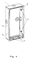
- prinziphaft einen Ausgleichseinsatz in Zuordnung eines Einbaugehäuses, räumlich in schräger Draufsicht.
- Fig. 1:
- in principle, an exploded view of the electrical / electronic installation device, in association with a built-in housing in a spatial representation;
- Fig. 2:
- in principle, an assembly of the electrical / electronic installation device and the installation housing according to
FIG. 1 in spatial representation; - 3:
- in principle, a plan view of an electrical / electronic installation device according to
FIG. 1 in the installed state; - 4:
- principle, a balance insert in association with an installation housing, spatially in oblique plan view.
Wie aus den Figuren hervorgeht, ist das elektrische/elektronische Installationsgerät zur wieder entnehmbaren Montage in ein Einbaugehäuse 1 vorgesehen. Das Einbaugehäuse 1 ist wiederum zur ortsfesten Installation in oder an (im Innenbereich oder im Außenbereich) Gebäuden vorgesehen. Das elektrische/elektronische Installationsgerät weist mehrere, an einer Trägeranordnung 2 festlegbare Funktionsmodule 3,4 auf, wobei an der Trägeranordnung 2 auch eine Designabdeckung 5 festlegbar ist. Die Trägeranordnung 2 ist zur Festlegung in dem Einbaugehäuse 1 vorgesehen. Um einen automatischen Putzausgleich auf einfache Art und Weise zu ermöglichen, ist im Einbaugehäuse 1 ein Ausgleichseinsatz A vorhanden, welcher in seiner Einbautiefe verstellbar im Einbaugehäuse 1 gehalten ist. Der Ausgleichseinsatz A ist also funktional dem Einbaugehäuse 1 zuzurechnen. Der Ausgleichseinsatz A weist zwei erste Rastmittel 9 auf, welche verrastend mit jeweils einem zugehörigen zweiten Rastmittel 8 zusammenwirken, welche jeweils an der Trägeranordnung 2 angebracht sind. Die beiden am Ausgleichseinsatz A vorhandenen ersten Rastmittel 9 sind jeweils in Art einer fensterartigen Öffnung ausgeführt und in zwei Seitenwände eingebracht, welche einander gegenüberliegend angeordnet sind. Die beiden an der Trägeranordnung 2 vorhandenen zweiten Rastmittel 8 sind jeweils in Art einer Rastfeder ausgeführt. Jedes der beiden zweiten Rastmittel 8 weist zwei Rastschenkel 8a auf, die zu ihrer Betätigung jeweils mit einer eigenen Betätigungsbasis 6 versehen sind. Die ersten Rastmittel 9 und die zweiten Rastmittel 8 sind durch die Designabdeckung 5 verdeckt angeordnet.As can be seen from the figures, the electrical / electronic installation device is provided for removable mounting in a
Wie des Weiteren aus den Figuren hervorgeht, weist jedes der beiden an der Trägeranordnung 2 angebrachte zweite Rastmittel 8 (Rastfeder) einen, zwischen den beiden Rastschenkeln 8a angeordneten Halteschenkel 7 auf. Die Anbringung der Rastfedern (zweite Rastmittel 8) an der Trägeranordnung 2 erfolgt über den Halteschenkel 7, an welchen zwei Rastnasen 7a angeformt sind, die jeweils eine entsprechend ausgeführte Rastkante 2a der Trägeranordnung 2 hintergreifen. Auf einfache Art und Weise sind somit die beiden zweiten Rastmittel 8 (Rastfedern) an der Trägeranordnung 2 positionsgenau festgelegt. Die Rastschenkel 8a und die als fensterartige Öffnungen ausgeführten ersten Rastmittel 9 sind maßlich derart aufeinander abgestimmt bzw. derart ausgelegt, dass während der Montage des elektrischen/elektronischen Installationsgerätes im Einbaugehäuse 1 bzw. Ausgleichseinsatz A eine Führung in senkrechter Richtung gewährleistet ist. Das bedeutete, dass das elektrische/elektronische Installationsgerät nicht durch eine Schwenkbewegung, sondern über eine senkrecht, hinsichtlich der Wand W verlaufende Einbaubewegung in das Einbaugehäuse 1 eingesetzt werden kann. Befindet sich das elektrische/elektronische Installationsgerät in seiner Festlegungsposition, wirken die als Rastfedern ausgeführten zweiten Rastmittel 8 unter Vorspannung mit den ersten Rastmitteln 9 zusammen. Das elektrische/elektronische Installationsgerät ist somit sicher gehalten im Einbaugehäuse 1 bzw. Ausgleichseinsatz A eingebaut.As further shown in the figures, each of the two attached to the
Wie zudem des Weiteren aus den Figuren hervorgeht, ist das Einbaugehäuse 1 in Art eines rechteckförmigen Kastens ausgeführt und der Ausgleichseinsatz A weist eine rahmenartige Ausführung auf und kommt mit seinen Außenwänden an den Innenwandungen des Einbaugehäuses 1 zur Anlage. Um auf einfache Art und Weise einen Putzausgleich zu realisieren, weist der Ausgleichseinsatz A vier in Montagerichtung verlaufende Schlitze S auf, welche mit Befestigungsschrauben B des Einbaugehäuses 1 zusammenwirken. Nach dem Einputzen des Einbaugehäuses 1 kann also auf einfache Art und Weise der Putzausgleich automatisch vorgenommen werden, indem der Ausgleichseinsatz A soweit in das Einbaugehäuse 1 eingeschoben wird, bis dieser mit seinem überkragenden Randbereich R auf der Wand W zur Anlage kommt. Anschließend wird der Ausgleichseinsatz A durch Anziehen der Befestigungsschrauben B im Einbaugehäuse 1 positionssicher festgesetzt. Um die Trägeranordnung 2 am Ausgleichseinsatz A beziehungsweise im Einbaugehäuse 1 auf einfache Art und Weise festzulegen, weist jeder der beiden zweiten Rastmittel 8 (Rastfedern) - wie bereits beschrieben - zwei federnd ausgeführte Rastschenkel 8a auf, welche verrastend mit den zugehörigen ersten Rastmitteln 9 (fensterartige Öffnungen) zusammenwirken, welche in den Ausgleichseinsatz A eingebracht sind. Automatisch schnappen die vier Rastschenkel 8a in die vier, als fensterartige Öffnungen ausgeführten ersten Rastmittel 9 ein, wenn die Trägeranordnung 2 in das Einbaugehäuse 1 beziehungsweise den Ausgleichseinsatz A eingesetzt wird. Die vier Rastschenkel 8a befinden sich unter Vorspannung durch Federrastung in ihrer Festlegungsposition. Das Einsetzen beziehungsweise die Einnahme der Festlegungsposition erfolgt einfach durch eine Eindrückbewegung, mit der die Trägeranordnung 2 selbst ohne einen Schwenkvorgang am Einbaugehäuse 1 beziehungsweise im Ausgleichseinsatz A festgelegt werden kann. Zur Entnahme der Trägeranordnung 2 aus dem Einbaugehäuse 1 werden die beiden Rastschenkel 8a eines der beiden zweiten Rastmittel 8 durch ein Entriegelungswerkzeug 10 betätigt, wobei das Entriegelungswerkzeug 10 jeweils mit der Betätigungsbasis 6 der beiden zugehörigen Rastschenkel 8a zusammenwirkt. Durch eine einfache Schiebebewegung werden die beiden Rastschenkel 8a durch das als Entriegelungsblech ausgeführte Entriegelungswerkzeug 10 aus ihrer Verrastung mit den beiden zugehörigen ersten Rastmittel 9 des Ausgleichseinsatzes A gelöst und in ihre Entnahmeposition gebracht. Die Entnahme des elektrischen/elektronischen Installationsgerätes aus dem Einbaugehäuse 1 bzw. Ausgleichseinsatz A ist nun ohne Weiteres auf bequeme Art und Weise möglich.As further shown in the figures, the
Üblicherweise ist das Einbaugehäuse 1 zur Unterputzmontage vorgesehen, weshalb ein automatischer Putzausgleich von besonderem Vorteil ist. Bei dem vorliegenden Ausführungsbeispiel ist das elektrische/elektronische Installationsgerät als Türkommunikationsgerät ausgebildet. Das elektrische/elektronische Installationsgerät kann dabei dem Außenbereich oder dem Innenbereich einer Eingangstür zugeordnet, also nahe der Eingangstür in die zugehörige Wand W des Gebäudes, eingebaut sein. Um für eine Abdichtung gegenüber der Oberfläche der Wand W Sorge zu tragen, ist die Designabdeckung 5 an ihrer, der Wand W zugeordneten Rückseite mit einer elastischen Dichtung D versehen. Das erste Funktionsmodul 3 weist bei dem vorliegenden Ausführungsbeispiel vier Betätigungstasten auf und ist dafür vorgesehen, anforderungsgerecht jeweils die zugehörige Türklingel in Funktion zu setzen. Das zweite Funktionsmodul 4 beinhaltet einen wesentlichen Teil der Funktionskomponenten der Türsprechanlage, ist also üblicherweise mit einem Lautsprecher, Mikrophon, elektrischen/elektronischen Steuerkomponenten und so weiter ausgerüstet. Um die Betätigungsmöglichkeit der zweiten Rastmittel 8 (Rastfedern) für Unbefugte zu erschweren, sind diese von der Designabdeckung 5 überdeckt.Usually, the
Wie des Weiteren aus den Figuren hervorgeht, erfolgt bei einem solchermaßen ausgebildeten elektrischen/elektronischen Installationsgerät die Festlegung im Einbaugehäuse 1 beziehungsweise am Ausgleichseinsatz A völlig werkzeuglos, weil durch einfaches Einsetzen eine automatische Verriegelung bzw. Verrastung erfolgt (Festlegungsposition). Das ist deshalb der Fall, weil beim Einsetzen die als Rastfedern ausgebildeten zweiten Rastmittel 8 im Sinne einer Federrastung mit den fensterartig ausgeführten ersten Rastmitteln 9 zusammenwirken und damit unter Vorspannung eine automatische Festlegung des elektrischen/elektronischen Installationsgerätes im Einbaugehäuse 1 beziehungsweise am Ausgleichseinsatz A bewirken. Bei der Entnahme ist zum Lösen der Verriegelung beziehungsweise Verrastung lediglich die verdeckt angeordnete Betätigungsbasis 6 der beiden Rastschenkel 8a von einem der beiden zweiten Rastmittel 8 mittels des Entriegelungswerkzeug 10 durch eine Schiebebewegung zu betätigen, womit die Verriegelung beziehungsweise Verrastung durch eine einfache, gradlinige Bewegung gelöst wird (Entnahmeposition). Danach kann das elektrische/elektronische Installationsgerät ohne weiteres Zutun einfach aus dem Einbaugehäuse 1 entnommen werden.As is further apparent from the figures, in such a trained electrical / electronic installation device fixing in the
Um bei Montage- oder Reparaturarbeiten die durchzuführenden Tätigkeiten für die damit betraute Person zu erleichtern, ist an der Trägeranordnung 2 eine laschenartige Halteanordnung 12 angebracht, welche einerseits zur Befestigung eines Halteseiles dient, welches andererseits am Einbaugehäuse 1 festgelegt ist, womit eine sichere Haltemöglichkeit für das aus dem Einbaugehäuse 1 entnommene elektrische/elektronische Installationsgerät realisiert ist. Der Einfachheit halber ist das Halteseil nicht dargestellt.In order to facilitate the activities to be performed for the person entrusted with assembly or repair work, a strap-like holding arrangement 12 is attached to the
- 11
- Einbaugehäuseinstallation housing
- 22
- Trägeranordnungcarrier assembly
- 2a2a
- Rastkantecatch edge
- 33
- Erstes FunktionsmodulFirst functional module
- 44
- Zweites FunktionsmodulSecond functional module
- 55
- Designabdeckungdesign cover
- 66
- Betätigungsbasisoperating base
- 77
- Halteschenkelholding leg
- 7a7a
- Rastnasenlocking lugs
- 88th
- Zweite RastmittelSecond locking means
- 8a8a
- Rastschenkellatching leg
- 99
- Erste RastmittelFirst locking means
- 1010
- Entriegelungswerkzeugunlocking
- AA
- Ausgleichseinsatzcompensation use
- BB
- Befestigungsschraubenmounting screws
- DD
- Dichtungpoetry
- RR
- Randbereichborder area
- SS
- Schlitzeslots
- WW
- Wandwall
Claims (10)
Priority Applications (1)
| Application Number | Priority Date | Filing Date | Title |
|---|---|---|---|
| PL14165106T PL2852016T3 (en) | 2013-09-23 | 2014-04-17 | Electric/electronic installation device |
Applications Claiming Priority (1)
| Application Number | Priority Date | Filing Date | Title |
|---|---|---|---|
| DE102013110460.6A DE102013110460B3 (en) | 2013-09-23 | 2013-09-23 | Electrical / electronic installation device |
Publications (3)
| Publication Number | Publication Date |
|---|---|
| EP2852016A2 true EP2852016A2 (en) | 2015-03-25 |
| EP2852016A3 EP2852016A3 (en) | 2015-06-03 |
| EP2852016B1 EP2852016B1 (en) | 2019-02-13 |
Family
ID=50488999
Family Applications (1)
| Application Number | Title | Priority Date | Filing Date |
|---|---|---|---|
| EP14165106.7A Active EP2852016B1 (en) | 2013-09-23 | 2014-04-17 | Electric/electronic installation device |
Country Status (4)
| Country | Link |
|---|---|
| EP (1) | EP2852016B1 (en) |
| DE (1) | DE102013110460B3 (en) |
| ES (1) | ES2725882T3 (en) |
| PL (1) | PL2852016T3 (en) |
Families Citing this family (1)
| Publication number | Priority date | Publication date | Assignee | Title |
|---|---|---|---|---|
| DE102014220307B3 (en) * | 2014-10-07 | 2016-01-07 | Berker Gmbh & Co. Kg | Fastening device for fixing a carrier arrangement of a door communication device in a mounting housing |
Citations (1)
| Publication number | Priority date | Publication date | Assignee | Title |
|---|---|---|---|---|
| DE102010016345B4 (en) | 2010-04-07 | 2011-11-24 | Berker Gmbh & Co. Kg | Control unit for a building installation system |
Family Cites Families (11)
| Publication number | Priority date | Publication date | Assignee | Title |
|---|---|---|---|---|
| AT206963B (en) * | 1957-10-24 | 1960-01-11 | Busch Jaeger Duerener Metall | Flush-mounted box with inserted support device for several installation devices |
| DE7038846U (en) * | 1970-10-21 | 1971-03-18 | Rittal-Werk R Loh Kg | Flush-mounted boxes, especially for intercoms |
| CH585472A5 (en) * | 1975-09-08 | 1977-02-28 | Feller Ag Adolf | |
| DE19525527C2 (en) * | 1995-07-13 | 1997-11-20 | Golos Selvin | Device for fastening installation devices in a flush-mounted box |
| DE19632536C2 (en) * | 1996-08-13 | 1999-05-27 | Maier & Cie C | Device for fastening a built-in device, in particular a socket |
| US5823821A (en) * | 1997-03-31 | 1998-10-20 | Tohanczyn, Jr.; Edward | Apparatus for securing an electrical outlet to an outlet box having stripped threads |
| US5913439A (en) * | 1997-08-29 | 1999-06-22 | Watlow Electric Manufacturing Co. | Mounting assembly with dual mount collar |
| EP1241741A1 (en) * | 2001-03-13 | 2002-09-18 | GIRA GIERSIEPEN GmbH. & CO. KG | Elecrical apparatus, specially multiple socket, for the installation into a mounting hole of a cable conduct |
| DE10229930B4 (en) * | 2002-07-04 | 2005-06-09 | Lic Langmatz Gmbh | Empty housing for housing a domestic connection box |
| DE102011108925A1 (en) * | 2011-07-27 | 2013-01-31 | Abb Ag | Mounting system of a station, in particular door station of a home communication system |
| EP2602888B1 (en) * | 2011-12-09 | 2015-11-25 | Schneider Electric Industries SAS | Releasable locking with angular adjustability |
-
2013
- 2013-09-23 DE DE102013110460.6A patent/DE102013110460B3/en not_active Expired - Fee Related
-
2014
- 2014-04-17 ES ES14165106T patent/ES2725882T3/en active Active
- 2014-04-17 EP EP14165106.7A patent/EP2852016B1/en active Active
- 2014-04-17 PL PL14165106T patent/PL2852016T3/en unknown
Patent Citations (1)
| Publication number | Priority date | Publication date | Assignee | Title |
|---|---|---|---|---|
| DE102010016345B4 (en) | 2010-04-07 | 2011-11-24 | Berker Gmbh & Co. Kg | Control unit for a building installation system |
Also Published As
| Publication number | Publication date |
|---|---|
| DE102013110460B3 (en) | 2014-07-31 |
| EP2852016B1 (en) | 2019-02-13 |
| ES2725882T3 (en) | 2019-09-30 |
| PL2852016T3 (en) | 2019-08-30 |
| EP2852016A3 (en) | 2015-06-03 |
Similar Documents
| Publication | Publication Date | Title |
|---|---|---|
| EP3873768A1 (en) | Charging device for electric vehicles | |
| DE102011053341A1 (en) | Electric / electronic device | |
| DE102008060347A1 (en) | Electrical/electronic installation device e.g. switch, for connection to e.g. installation network bus system of building automation system, has contact element that is component of auxiliary module which is coupled to plastic housing | |
| DE102012101609A1 (en) | Assembly module for wall mounting of LCD touch panel of display unit that is utilized for displaying information about e.g. parameter of building equipment, has diaphragm connected with base element using locking element | |
| EP2852016B1 (en) | Electric/electronic installation device | |
| DE102011000448B4 (en) | Installation device for an electrical installation system | |
| EP4016007A1 (en) | Electric/electronic installation device | |
| DE102007051335A1 (en) | Control panel for an electrical appliance | |
| DE102017006870A1 (en) | Electrical installation device | |
| DE102014103713B3 (en) | Electrical / electronic installation device | |
| EP2453541B1 (en) | Electric switching gear assembly | |
| EP2348598B1 (en) | Electrical built-in installation device for a mobile audio device | |
| DE102007045869B3 (en) | Electrical/electronic installation device e.g. push-button, for e.g. sensor installed in building, has opening provided for passage of electrical lines, and connection block provided in rear wall in region of supporting frame | |
| DE102013110461A1 (en) | Electrical / electronic installation device | |
| DE102013105893B3 (en) | Electrical / electronic installation device | |
| DE102014110652B3 (en) | Electrical / electronic installation device | |
| DE202017104726U1 (en) | Electrical installation device | |
| DE102014220307B3 (en) | Fastening device for fixing a carrier arrangement of a door communication device in a mounting housing | |
| EP2351176B1 (en) | Electrical installation apparatus | |
| DE202021001123U1 (en) | Meter plug-in terminal for connecting electrical lines to an electricity meter with three-point attachment | |
| DE202014004926U1 (en) | Plant module with fasteners | |
| EP3503310B1 (en) | Electric/electronic installation device | |
| DE102017130675A1 (en) | Electrical / electronic installation device | |
| DE102023200638B3 (en) | Accessories for an electric switch and an electric switch with such accessories | |
| DE102013105894B4 (en) | Electrical / electronic installation device |
Legal Events
| Date | Code | Title | Description |
|---|---|---|---|
| PUAI | Public reference made under article 153(3) epc to a published international application that has entered the european phase |
Free format text: ORIGINAL CODE: 0009012 |
|
| 17P | Request for examination filed |
Effective date: 20140417 |
|
| AK | Designated contracting states |
Kind code of ref document: A2 Designated state(s): AL AT BE BG CH CY CZ DE DK EE ES FI FR GB GR HR HU IE IS IT LI LT LU LV MC MK MT NL NO PL PT RO RS SE SI SK SM TR |
|
| AX | Request for extension of the european patent |
Extension state: BA ME |
|
| PUAL | Search report despatched |
Free format text: ORIGINAL CODE: 0009013 |
|
| AK | Designated contracting states |
Kind code of ref document: A3 Designated state(s): AL AT BE BG CH CY CZ DE DK EE ES FI FR GB GR HR HU IE IS IT LI LT LU LV MC MK MT NL NO PL PT RO RS SE SI SK SM TR |
|
| AX | Request for extension of the european patent |
Extension state: BA ME |
|
| RIC1 | Information provided on ipc code assigned before grant |
Ipc: H02G 3/12 20060101ALI20150428BHEP Ipc: H02G 3/08 20060101AFI20150428BHEP |
|
| R17P | Request for examination filed (corrected) |
Effective date: 20151203 |
|
| RBV | Designated contracting states (corrected) |
Designated state(s): AL AT BE BG CH CY CZ DE DK EE ES FI FR GB GR HR HU IE IS IT LI LT LU LV MC MK MT NL NO PL PT RO RS SE SI SK SM TR |
|
| STAA | Information on the status of an ep patent application or granted ep patent |
Free format text: STATUS: EXAMINATION IS IN PROGRESS |
|
| 17Q | First examination report despatched |
Effective date: 20170526 |
|
| GRAP | Despatch of communication of intention to grant a patent |
Free format text: ORIGINAL CODE: EPIDOSNIGR1 |
|
| STAA | Information on the status of an ep patent application or granted ep patent |
Free format text: STATUS: GRANT OF PATENT IS INTENDED |
|
| INTG | Intention to grant announced |
Effective date: 20180903 |
|
| GRAS | Grant fee paid |
Free format text: ORIGINAL CODE: EPIDOSNIGR3 |
|
| GRAA | (expected) grant |
Free format text: ORIGINAL CODE: 0009210 |
|
| STAA | Information on the status of an ep patent application or granted ep patent |
Free format text: STATUS: THE PATENT HAS BEEN GRANTED |
|
| AK | Designated contracting states |
Kind code of ref document: B1 Designated state(s): AL AT BE BG CH CY CZ DE DK EE ES FI FR GB GR HR HU IE IS IT LI LT LU LV MC MK MT NL NO PL PT RO RS SE SI SK SM TR |
|
| REG | Reference to a national code |
Ref country code: GB Ref legal event code: FG4D Free format text: NOT ENGLISH |
|
| REG | Reference to a national code |
Ref country code: CH Ref legal event code: EP Ref country code: AT Ref legal event code: REF Ref document number: 1096745 Country of ref document: AT Kind code of ref document: T Effective date: 20190215 |
|
| REG | Reference to a national code |
Ref country code: IE Ref legal event code: FG4D Free format text: LANGUAGE OF EP DOCUMENT: GERMAN |
|
| REG | Reference to a national code |
Ref country code: DE Ref legal event code: R096 Ref document number: 502014010788 Country of ref document: DE |
|
| REG | Reference to a national code |
Ref country code: LT Ref legal event code: MG4D |
|
| REG | Reference to a national code |
Ref country code: NL Ref legal event code: MP Effective date: 20190213 |
|
| PG25 | Lapsed in a contracting state [announced via postgrant information from national office to epo] |
Ref country code: FI Free format text: LAPSE BECAUSE OF FAILURE TO SUBMIT A TRANSLATION OF THE DESCRIPTION OR TO PAY THE FEE WITHIN THE PRESCRIBED TIME-LIMIT Effective date: 20190213 Ref country code: LT Free format text: LAPSE BECAUSE OF FAILURE TO SUBMIT A TRANSLATION OF THE DESCRIPTION OR TO PAY THE FEE WITHIN THE PRESCRIBED TIME-LIMIT Effective date: 20190213 Ref country code: NL Free format text: LAPSE BECAUSE OF FAILURE TO SUBMIT A TRANSLATION OF THE DESCRIPTION OR TO PAY THE FEE WITHIN THE PRESCRIBED TIME-LIMIT Effective date: 20190213 Ref country code: SE Free format text: LAPSE BECAUSE OF FAILURE TO SUBMIT A TRANSLATION OF THE DESCRIPTION OR TO PAY THE FEE WITHIN THE PRESCRIBED TIME-LIMIT Effective date: 20190213 Ref country code: PT Free format text: LAPSE BECAUSE OF FAILURE TO SUBMIT A TRANSLATION OF THE DESCRIPTION OR TO PAY THE FEE WITHIN THE PRESCRIBED TIME-LIMIT Effective date: 20190613 Ref country code: NO Free format text: LAPSE BECAUSE OF FAILURE TO SUBMIT A TRANSLATION OF THE DESCRIPTION OR TO PAY THE FEE WITHIN THE PRESCRIBED TIME-LIMIT Effective date: 20190513 |
|
| PG25 | Lapsed in a contracting state [announced via postgrant information from national office to epo] |
Ref country code: RS Free format text: LAPSE BECAUSE OF FAILURE TO SUBMIT A TRANSLATION OF THE DESCRIPTION OR TO PAY THE FEE WITHIN THE PRESCRIBED TIME-LIMIT Effective date: 20190213 Ref country code: GR Free format text: LAPSE BECAUSE OF FAILURE TO SUBMIT A TRANSLATION OF THE DESCRIPTION OR TO PAY THE FEE WITHIN THE PRESCRIBED TIME-LIMIT Effective date: 20190514 Ref country code: LV Free format text: LAPSE BECAUSE OF FAILURE TO SUBMIT A TRANSLATION OF THE DESCRIPTION OR TO PAY THE FEE WITHIN THE PRESCRIBED TIME-LIMIT Effective date: 20190213 Ref country code: HR Free format text: LAPSE BECAUSE OF FAILURE TO SUBMIT A TRANSLATION OF THE DESCRIPTION OR TO PAY THE FEE WITHIN THE PRESCRIBED TIME-LIMIT Effective date: 20190213 Ref country code: IS Free format text: LAPSE BECAUSE OF FAILURE TO SUBMIT A TRANSLATION OF THE DESCRIPTION OR TO PAY THE FEE WITHIN THE PRESCRIBED TIME-LIMIT Effective date: 20190613 Ref country code: BG Free format text: LAPSE BECAUSE OF FAILURE TO SUBMIT A TRANSLATION OF THE DESCRIPTION OR TO PAY THE FEE WITHIN THE PRESCRIBED TIME-LIMIT Effective date: 20190513 |
|
| REG | Reference to a national code |
Ref country code: ES Ref legal event code: FG2A Ref document number: 2725882 Country of ref document: ES Kind code of ref document: T3 Effective date: 20190930 |
|
| PG25 | Lapsed in a contracting state [announced via postgrant information from national office to epo] |
Ref country code: EE Free format text: LAPSE BECAUSE OF FAILURE TO SUBMIT A TRANSLATION OF THE DESCRIPTION OR TO PAY THE FEE WITHIN THE PRESCRIBED TIME-LIMIT Effective date: 20190213 Ref country code: CZ Free format text: LAPSE BECAUSE OF FAILURE TO SUBMIT A TRANSLATION OF THE DESCRIPTION OR TO PAY THE FEE WITHIN THE PRESCRIBED TIME-LIMIT Effective date: 20190213 Ref country code: RO Free format text: LAPSE BECAUSE OF FAILURE TO SUBMIT A TRANSLATION OF THE DESCRIPTION OR TO PAY THE FEE WITHIN THE PRESCRIBED TIME-LIMIT Effective date: 20190213 Ref country code: DK Free format text: LAPSE BECAUSE OF FAILURE TO SUBMIT A TRANSLATION OF THE DESCRIPTION OR TO PAY THE FEE WITHIN THE PRESCRIBED TIME-LIMIT Effective date: 20190213 Ref country code: SK Free format text: LAPSE BECAUSE OF FAILURE TO SUBMIT A TRANSLATION OF THE DESCRIPTION OR TO PAY THE FEE WITHIN THE PRESCRIBED TIME-LIMIT Effective date: 20190213 Ref country code: AL Free format text: LAPSE BECAUSE OF FAILURE TO SUBMIT A TRANSLATION OF THE DESCRIPTION OR TO PAY THE FEE WITHIN THE PRESCRIBED TIME-LIMIT Effective date: 20190213 |
|
| REG | Reference to a national code |
Ref country code: DE Ref legal event code: R097 Ref document number: 502014010788 Country of ref document: DE |
|
| PG25 | Lapsed in a contracting state [announced via postgrant information from national office to epo] |
Ref country code: SM Free format text: LAPSE BECAUSE OF FAILURE TO SUBMIT A TRANSLATION OF THE DESCRIPTION OR TO PAY THE FEE WITHIN THE PRESCRIBED TIME-LIMIT Effective date: 20190213 |
|
| REG | Reference to a national code |
Ref country code: CH Ref legal event code: PL |
|
| PLBE | No opposition filed within time limit |
Free format text: ORIGINAL CODE: 0009261 |
|
| STAA | Information on the status of an ep patent application or granted ep patent |
Free format text: STATUS: NO OPPOSITION FILED WITHIN TIME LIMIT |
|
| PG25 | Lapsed in a contracting state [announced via postgrant information from national office to epo] |
Ref country code: LU Free format text: LAPSE BECAUSE OF NON-PAYMENT OF DUE FEES Effective date: 20190417 Ref country code: MC Free format text: LAPSE BECAUSE OF FAILURE TO SUBMIT A TRANSLATION OF THE DESCRIPTION OR TO PAY THE FEE WITHIN THE PRESCRIBED TIME-LIMIT Effective date: 20190213 |
|
| 26N | No opposition filed |
Effective date: 20191114 |
|
| PG25 | Lapsed in a contracting state [announced via postgrant information from national office to epo] |
Ref country code: LI Free format text: LAPSE BECAUSE OF NON-PAYMENT OF DUE FEES Effective date: 20190430 Ref country code: CH Free format text: LAPSE BECAUSE OF NON-PAYMENT OF DUE FEES Effective date: 20190430 |
|
| PG25 | Lapsed in a contracting state [announced via postgrant information from national office to epo] |
Ref country code: SI Free format text: LAPSE BECAUSE OF FAILURE TO SUBMIT A TRANSLATION OF THE DESCRIPTION OR TO PAY THE FEE WITHIN THE PRESCRIBED TIME-LIMIT Effective date: 20190213 |
|
| PG25 | Lapsed in a contracting state [announced via postgrant information from national office to epo] |
Ref country code: TR Free format text: LAPSE BECAUSE OF FAILURE TO SUBMIT A TRANSLATION OF THE DESCRIPTION OR TO PAY THE FEE WITHIN THE PRESCRIBED TIME-LIMIT Effective date: 20190213 |
|
| PG25 | Lapsed in a contracting state [announced via postgrant information from national office to epo] |
Ref country code: IE Free format text: LAPSE BECAUSE OF NON-PAYMENT OF DUE FEES Effective date: 20190417 |
|
| PG25 | Lapsed in a contracting state [announced via postgrant information from national office to epo] |
Ref country code: CY Free format text: LAPSE BECAUSE OF FAILURE TO SUBMIT A TRANSLATION OF THE DESCRIPTION OR TO PAY THE FEE WITHIN THE PRESCRIBED TIME-LIMIT Effective date: 20190213 |
|
| PG25 | Lapsed in a contracting state [announced via postgrant information from national office to epo] |
Ref country code: HU Free format text: LAPSE BECAUSE OF FAILURE TO SUBMIT A TRANSLATION OF THE DESCRIPTION OR TO PAY THE FEE WITHIN THE PRESCRIBED TIME-LIMIT; INVALID AB INITIO Effective date: 20140417 Ref country code: MT Free format text: LAPSE BECAUSE OF FAILURE TO SUBMIT A TRANSLATION OF THE DESCRIPTION OR TO PAY THE FEE WITHIN THE PRESCRIBED TIME-LIMIT Effective date: 20190213 |
|
| PG25 | Lapsed in a contracting state [announced via postgrant information from national office to epo] |
Ref country code: MK Free format text: LAPSE BECAUSE OF FAILURE TO SUBMIT A TRANSLATION OF THE DESCRIPTION OR TO PAY THE FEE WITHIN THE PRESCRIBED TIME-LIMIT Effective date: 20190213 |
|
| P01 | Opt-out of the competence of the unified patent court (upc) registered |
Effective date: 20230606 |
|
| PGFP | Annual fee paid to national office [announced via postgrant information from national office to epo] |
Ref country code: DE Payment date: 20250429 Year of fee payment: 12 |
|
| PGFP | Annual fee paid to national office [announced via postgrant information from national office to epo] |
Ref country code: GB Payment date: 20250428 Year of fee payment: 12 Ref country code: ES Payment date: 20250505 Year of fee payment: 12 |
|
| PGFP | Annual fee paid to national office [announced via postgrant information from national office to epo] |
Ref country code: IT Payment date: 20250422 Year of fee payment: 12 Ref country code: BE Payment date: 20250428 Year of fee payment: 12 |
|
| PGFP | Annual fee paid to national office [announced via postgrant information from national office to epo] |
Ref country code: FR Payment date: 20250425 Year of fee payment: 12 |
|
| PGFP | Annual fee paid to national office [announced via postgrant information from national office to epo] |
Ref country code: AT Payment date: 20250402 Year of fee payment: 12 |
|
| PGFP | Annual fee paid to national office [announced via postgrant information from national office to epo] |
Ref country code: PL Payment date: 20260331 Year of fee payment: 13 |