EP2851111B1 - Luftfiltersystem und Verwendung eines Luftffilterelements in einem Luftffiltersystem - Google Patents
Luftfiltersystem und Verwendung eines Luftffilterelements in einem Luftffiltersystem Download PDFInfo
- Publication number
- EP2851111B1 EP2851111B1 EP14182365.8A EP14182365A EP2851111B1 EP 2851111 B1 EP2851111 B1 EP 2851111B1 EP 14182365 A EP14182365 A EP 14182365A EP 2851111 B1 EP2851111 B1 EP 2851111B1
- Authority
- EP
- European Patent Office
- Prior art keywords
- housing
- end disk
- filter element
- support tube
- filter system
- Prior art date
- Legal status (The legal status is an assumption and is not a legal conclusion. Google has not performed a legal analysis and makes no representation as to the accuracy of the status listed.)
- Active
Links
Images


Classifications
-
- F—MECHANICAL ENGINEERING; LIGHTING; HEATING; WEAPONS; BLASTING
- F02—COMBUSTION ENGINES; HOT-GAS OR COMBUSTION-PRODUCT ENGINE PLANTS
- F02M—SUPPLYING COMBUSTION ENGINES IN GENERAL WITH COMBUSTIBLE MIXTURES OR CONSTITUENTS THEREOF
- F02M35/00—Combustion-air cleaners, air intakes, intake silencers, or induction systems specially adapted for, or arranged on, internal-combustion engines
- F02M35/02—Air cleaners
- F02M35/024—Air cleaners using filters, e.g. moistened
- F02M35/02475—Air cleaners using filters, e.g. moistened characterised by the shape of the filter element
- F02M35/02483—Cylindrical, conical, oval, spherical or the like filter elements; wounded filter elements
-
- B—PERFORMING OPERATIONS; TRANSPORTING
- B01—PHYSICAL OR CHEMICAL PROCESSES OR APPARATUS IN GENERAL
- B01D—SEPARATION
- B01D46/00—Filters or filtering processes specially modified for separating dispersed particles from gases or vapours
- B01D46/0039—Filters or filtering processes specially modified for separating dispersed particles from gases or vapours with flow guiding by feed or discharge devices
- B01D46/0041—Filters or filtering processes specially modified for separating dispersed particles from gases or vapours with flow guiding by feed or discharge devices for feeding
- B01D46/0046—Filters or filtering processes specially modified for separating dispersed particles from gases or vapours with flow guiding by feed or discharge devices for feeding provoking a tangential stream
-
- B—PERFORMING OPERATIONS; TRANSPORTING
- B01—PHYSICAL OR CHEMICAL PROCESSES OR APPARATUS IN GENERAL
- B01D—SEPARATION
- B01D46/00—Filters or filtering processes specially modified for separating dispersed particles from gases or vapours
- B01D46/24—Particle separators, e.g. dust precipitators, using rigid hollow filter bodies
- B01D46/2403—Particle separators, e.g. dust precipitators, using rigid hollow filter bodies characterised by the physical shape or structure of the filtering element
- B01D46/2411—Filter cartridges
- B01D46/2414—End caps including additional functions or special forms
-
- B—PERFORMING OPERATIONS; TRANSPORTING
- B01—PHYSICAL OR CHEMICAL PROCESSES OR APPARATUS IN GENERAL
- B01D—SEPARATION
- B01D46/00—Filters or filtering processes specially modified for separating dispersed particles from gases or vapours
- B01D46/52—Particle separators, e.g. dust precipitators, using filters embodying folded corrugated or wound sheet material
- B01D46/521—Particle separators, e.g. dust precipitators, using filters embodying folded corrugated or wound sheet material using folded, pleated material
-
- B—PERFORMING OPERATIONS; TRANSPORTING
- B01—PHYSICAL OR CHEMICAL PROCESSES OR APPARATUS IN GENERAL
- B01D—SEPARATION
- B01D46/00—Filters or filtering processes specially modified for separating dispersed particles from gases or vapours
- B01D46/56—Filters or filtering processes specially modified for separating dispersed particles from gases or vapours with multiple filtering elements, characterised by their mutual disposition
- B01D46/62—Filters or filtering processes specially modified for separating dispersed particles from gases or vapours with multiple filtering elements, characterised by their mutual disposition connected in series
- B01D46/64—Filters or filtering processes specially modified for separating dispersed particles from gases or vapours with multiple filtering elements, characterised by their mutual disposition connected in series arranged concentrically or coaxially
-
- B—PERFORMING OPERATIONS; TRANSPORTING
- B01—PHYSICAL OR CHEMICAL PROCESSES OR APPARATUS IN GENERAL
- B01D—SEPARATION
- B01D50/00—Combinations of methods or devices for separating particles from gases or vapours
- B01D50/20—Combinations of devices covered by groups B01D45/00 and B01D46/00
-
- F—MECHANICAL ENGINEERING; LIGHTING; HEATING; WEAPONS; BLASTING
- F02—COMBUSTION ENGINES; HOT-GAS OR COMBUSTION-PRODUCT ENGINE PLANTS
- F02M—SUPPLYING COMBUSTION ENGINES IN GENERAL WITH COMBUSTIBLE MIXTURES OR CONSTITUENTS THEREOF
- F02M35/00—Combustion-air cleaners, air intakes, intake silencers, or induction systems specially adapted for, or arranged on, internal-combustion engines
- F02M35/02—Air cleaners
- F02M35/0201—Housings; Casings; Frame constructions; Lids; Manufacturing or assembling thereof
- F02M35/0202—Manufacturing or assembling; Materials for air cleaner housings
- F02M35/0203—Manufacturing or assembling; Materials for air cleaner housings by using clamps, catches, locks or the like, e.g. for disposable plug-in filter cartridges
-
- F—MECHANICAL ENGINEERING; LIGHTING; HEATING; WEAPONS; BLASTING
- F02—COMBUSTION ENGINES; HOT-GAS OR COMBUSTION-PRODUCT ENGINE PLANTS
- F02M—SUPPLYING COMBUSTION ENGINES IN GENERAL WITH COMBUSTIBLE MIXTURES OR CONSTITUENTS THEREOF
- F02M35/00—Combustion-air cleaners, air intakes, intake silencers, or induction systems specially adapted for, or arranged on, internal-combustion engines
- F02M35/02—Air cleaners
- F02M35/024—Air cleaners using filters, e.g. moistened
- F02M35/02416—Fixing, mounting, supporting or arranging filter elements; Filter element cartridges
-
- B—PERFORMING OPERATIONS; TRANSPORTING
- B01—PHYSICAL OR CHEMICAL PROCESSES OR APPARATUS IN GENERAL
- B01D—SEPARATION
- B01D2265/00—Casings, housings or mounting for filters specially adapted for separating dispersed particles from gases or vapours
- B01D2265/02—Non-permanent measures for connecting different parts of the filter
- B01D2265/021—Anti-rotational means
-
- B—PERFORMING OPERATIONS; TRANSPORTING
- B01—PHYSICAL OR CHEMICAL PROCESSES OR APPARATUS IN GENERAL
- B01D—SEPARATION
- B01D2265/00—Casings, housings or mounting for filters specially adapted for separating dispersed particles from gases or vapours
- B01D2265/02—Non-permanent measures for connecting different parts of the filter
- B01D2265/024—Mounting aids
- B01D2265/026—Mounting aids with means for avoiding false mounting
-
- B—PERFORMING OPERATIONS; TRANSPORTING
- B01—PHYSICAL OR CHEMICAL PROCESSES OR APPARATUS IN GENERAL
- B01D—SEPARATION
- B01D2265/00—Casings, housings or mounting for filters specially adapted for separating dispersed particles from gases or vapours
- B01D2265/06—Details of supporting structures for filtering material, e.g. cores
Definitions
- the invention relates to an air filter system, in particular for use as an air filter of an internal combustion engine, as well as the use of a filter element for installation in such a filter system.
- the documents US 2010/146917 A1 and US 2012/067017 A1 show circular air filter elements with projecting into the interior of the filter element end plates.
- the documents DE 42 41 586 C1 and DE 197 12 679 A1 show round air filter with housing-fixed support tube and secondary filter element.
- From the WO 2009/047196 A1 is a filter system for internal combustion engines with a filter element known.
- This filter system is used in particular for filtering the intake air of an internal combustion engine and consists of a housing and a lid for receiving the filter element, which is ensured by the design of the seals of the filter element with two ring-bead-shaped arrangements and an intermediate sealing groove, on the one hand a sealing effect and on the other an axial support of the filter element is achieved in a housing.
- plastic for sealing vibration-loaded elements a design is required, which works reliably even with extreme temperature fluctuations.
- a secondary element which is positioned inside a filter element of the filter system.
- the secondary element has the task of keeping the outlet of the filter system still closed when replacing the filter element, so that no dirt can penetrate into this area while the filter element is being cleaned or replaced.
- the purified air passes through the secondary element which has a nonwoven overlay on a supporting structure.
- the secondary element is attached via a screw thread to the outlet of the outlet and at the same time sealed by an O-ring in this area.
- the filter elements of air filters after a certain period of operation.
- the service life of an air filter can be a few days (construction machinery) up to several months.
- the secondary element which is arranged on the clean air side, remains in the filter system.
- the secondary element also heavily loaded with dirt, so it must also be replaced, otherwise the air flow is reduced too much.
- the reliable and process-reliable sealing of filter element and secondary element in a housing is particularly important in order to protect the intake tract of a subsequent internal combustion engine from penetrating dirt.
- An object of the invention is therefore to provide a filter system in which a reliable seal between the region of the unfiltered and the region of the filtered medium is possible, which maintained both during operation and in particular after an easy installation replacement of filter element and / or Secondary element can be reliably restored.
- Another object of the invention is to provide a filter element and a secondary element for installation in such a filter system.
- a filter system comprising a housing with a longitudinal axis, a lid which closes the housing at one end face, an inlet arranged on the housing for supplying a medium to be filtered and one on the housing arranged outlet for discharging the filtered medium, an exchangeable filter element, which is arranged in the housing and a filter body, a first disposed on one end side open end plate and a second disposed on the opposite end face end plate comprises, and a housing-fixed support tube, which in the interior of the filter element is arranged concentrically about the longitudinal axis and in particular serves for the radial support of the filter element comprises.
- the filter element according to the invention with the second end plate resting on the support tube resting against an inner cover contour is mounted against rotation and so firmly pressed between the support tube and cover.
- the storage of the filter element itself in the housing is less sensitive and clear to environmental influences such as water entry, high humidity, and thereby occurring softening / deformation of the filter paper of the filter body during operation.
- this provides a reliable seal between the region of the unfiltered and the region of the filtered medium, which can be maintained both during operation and can be reliably restored, in particular after a replacement of filter element and / or secondary element easy to install.
- a plurality of eccentric support nipples arranged in a circle around the longitudinal axis and provided with regular or irregular spacing are provided on the second end disk.
- the support nubs are arranged on a circle with the diameter of the support tube.
- the filter body may for example consist of a zigzag-folded (pleated) filter bellows and be executed closed annular.
- the folding can be produced for example by knife folding, for longer filter body, or rotational folding.
- the filter bellows may for example consist of paper or cellulose or of a mixed fiber of plastic and cellulose.
- the filter bellows may also have a smooth surface, rolled and / or designed in different embossing shapes Be performed surface for stiffening and / or creation of cavities for dust deposition.
- the filter bellows may have a coating and / or impregnation to repel moisture. It may alternatively be coated with nanofibers.
- the filter body may further be structurally stiffened with a filament winding, at least one circulating melt adhesive bead or a grid.
- Thread winding is understood to mean a thread soaked in hot melt adhesive which is wound onto the circumference of the filter body formed by the outer folding edges, the thread being stiffened and being connected to the pleat tips during curing of the hot melt adhesive.
- the filter element is designed as a main filter element, on the clean side and / or in the interior of which a secondary filter element can still be arranged.
- the filter system may comprise a replaceable secondary element having an open end and a closed end disposed inside the support tube and attached to the open end in a housing seat.
- the filter element with the second end disk on the support tube and / or on the closed end of the secondary element lying resting against an inner cover contour can be mounted against rotation.
- the secondary element may be pressed into the housing seat or be pressed by applying force on the second end plate in the housing seat.
- the support tube may have at its end facing the second end plate recesses with which the second end plate is toothed or toothed.
- the clawing of the support tube in the material of the end plate makes the filter element less sensitive to vibration.
- the cover of the housing has rib-shaped elevations with which the second end disk of the filter element is toothed or toothed.
- the additional anti-rotation effect of the claw with the rib-shaped elevations in the lid favors the vibration resistance of the storage of the filter element in the housing even further.
- the second end disk has an outer, middle support surface which preferably extends perpendicular to the central axis or longitudinal axis of the filter element.
- a parallel, inner support surface is further preferably formed by the inside of the second end plate.
- the second end disk can have supporting nubs for the axial and / or radial power transmission between the cover and the second end disk. In this way, the force exerted on the closing of the cover force can be passed through the end plate through this and introduced into the support tube, resulting in a fixed mounting of the filter element.
- the second end disk can also have supporting knobs for the axial and / or radial force transmission between the cover and the secondary element.
- the force exerted on the closing of the lid force can be passed through the end plate through this and introduced into the secondary element, whereby this in turn can be pressed firmly into its housing seat. This is a fixed storage of the secondary element and at the same time good sealing between unfiltered and filtered area of the filter system is possible.
- the second end disk as well as the first end disk, consist of a polyurethane foam or an elastomer.
- the end plate of several plastic components, so as to ensure optimum deformability over a wide temperature range, as it can occur in practice. So thermoplastic materials are not excluded. Both end plates can be welded or glued to the filter body to effect a stable connection.
- the inner cover contour can be formed, for example, in an area as an annular groove, in which support studs engage so that a radial support on the radial walls of the groove is possible.
- a central Abstütznoppe in the region of the longitudinal axis of the filter element and a plurality of annular or circular around the longitudinal axis arranged around, regularly or irregularly spaced, eccentric Abstweilnoppen provided at the second end plate.
- the support nubs are preferably made in one piece and / or of the same material with the second end disk.
- the central Abstütznoppe may preferably form the outer, central support surface.
- the radial position, i. the distance from the center of the second end disk of the eccentric Abstütznoppen is preferably selected so that the eccentric AbstNeillnoppen are arranged in direct axial continuation of a support tube of a corresponding housing.
- the eccentric Abstweilnoppen for example, arranged on a circle with the diameter of the support tube.
- the power flow is preferably carried out purely axially from the support tube via the second end plate and the eccentric Abstweilnoppen on the inner lid contour of the lid.
- the inner lid contour has in the middle of the lid preferably on a flat surface on which the central Abstweilnoppe is supportable.
- the second end disk is preferably elastic at least in the area annularly enclosed by the filter body designed so that the central region can be pressed with the central Abstweilnoppe from the secondary element elastically outwards until it rests against the lid.
- the eccentric Abstweilnoppen relative to the central Abstütznoppe slightly shifted towards open end plate.
- the second end plate is slightly biased and facilitates the removal of the filter element from its frictional sealing seat on the open end plate, as with the cover removed train on the outer regions of the second end plate and thus the filter body is exercised ,
- rib-shaped preferably radially extending, more preferably easily in the interior of the filter housing extending, surveys mounted with which interlock or dig the elastic material of the second end plate , so that the filter element is thereby secured against possible rotation during vibration during operation.
- the elevations are preferably pressed into the eccentric Abstütznoppen the second end plate, so that a positive connection in the direction of rotation about the longitudinal axis is achieved.
- recesses are also conceivable additionally or alternatively at the end of the support tube facing the second end plate, which likewise enable toothing or clawing of the support tube with the second end disc so as to ensure a rotation-proof securing of the filter element in the event of vibrations.
- the second end plate connects, for example, positively with the second end plate facing the end of the support tube, for example, a resilient second end plate penetrate into the recesses by deformation and / or compression during assembly, so that a positive connection in the direction of rotation about the longitudinal axis is achieved.
- a further embodiment is advantageous, in which the second end plate of an example cast, compared to the housing material and support tube material (both usually injection molded thermoplastics, in particular glass fiber content, or metal) soft material is used, expediently polyurethane foam or a similar elastic material, preferably having a hardness in the range of about 10-30 Shore A.
- the distance between the inner surface of the second end disk and the axial outer surfaces of the support studs is preferably equal to or more preferably selected to be slightly larger than the distance between the inner surface of the cover in the region of the longitudinal axis, i. in the center, and the axial end of the secondary element or between the inner surface of the lid in the region of the inner lid contour and the support tube.
- At least one of said distances at the second end disk is designed with an excess of 1-5 mm, preferably based on the distances defined by the cover on the one hand and the support pipe and the secondary element on the other hand. In this way, a reliable fixed bearing of the filter element can be ensured.
- the first end plate may have a radial seal relative to the housing.
- This has the advantage that in addition to a good seal and thus a secure filter effect, a radial guidance of the filter element in the housing can be effected by the radial seal and the axial clamping of the support studs in the lid and thus a very stable mounting of the filter element is formed in the housing.
- the secondary element which is connected to the housing, remain when changing the filter element in the housing. In this way it is ensured that the adjoining the outlet of the filter housing further air duct is protected from contamination during the exchange process.
- a cyclone separator may be provided in the region of the inlet of the filter system and a dirt outlet may be provided on the housing or on the lid.
- This cyclone separator consists of a guide geometry, which sets the medium to be filtered into a rotation. Through this rotation, the dirt in the Concentrated area of the housing wall and discharged at a suitable location via a dirt outlet.
- the filter system can be used as an air filter, in particular as an air filter of an internal combustion engine.
- the safe operation of internal combustion engines is also based on a safe and cheap filtering of the intake air for combustion operation.
- the filter element described represents an economical possibility for this.
- the filter system as a particle filter, in particular as a particle filter of an internal combustion engine.
- the safe installation and economic interchangeability of the filter element described are of crucial importance.
- the invention relates to a filter element for installation in a filter system and preferably with one or more features as described above and below, wherein the filter element can be arranged replaceably in the housing of the filter system.
- the use of such a filter element in a described filter system provides a reliable seal between the area of the unfiltered and the area of the filtered medium, which can be maintained both during operation and in particular can be reliably restored after an easy replacement of the filter element.
- the invention relates to a secondary element for installation in a filter system as described above, wherein the secondary element is interchangeable in the housing of the filter system can be arranged.
- the use of such a secondary element in a described filter system provides a reliable seal between the area of the unfiltered and the area of the filtered medium, which can be maintained both during operation and can be reliably restored after a replacement of the secondary element that is easy to assemble.
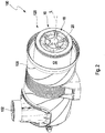
- FIG. 1 shows a perspective view of a filter system 100 according to an embodiment of the invention with tangential inlet 102, centric outlet 104 and bottom dirt outlet 106. Shown is a round filter design comprising a housing 108 which is closed at an end face 120 with a lid 110.
- dust-laden air flows through the inlet 102, which is arranged tangentially to the housing wall and internally installed air filter element, also tangentially into the raw air flow surrounding the air filter element, so that the air is set inside the housing 108 in a rotational movement.
- a direct penetration of the air entering through the inlet 102 into the folds of the air filter element present in the inlet region is prevented by a flow protection on the filter element, which is formed, for example, by a film surrounding the filter element in the inflow region and forming a part of the filter element.
- the onflow protection can also be formed by a wall surrounding the filter element in the inflow region and extending from the outlet-side, axial housing wall into the interior of the filter housing. Filter element and Anströmtik are not shown in the drawing. Due to the cyclone effect caused by the rotational movement of the air, centrifugal forces act on the dust particles of the flowing air, so that they can be partly deposited on the housing wall and can flow out of the filter system 100 via the dirt outlet 106. As a result, the filter element is less stressed. The cleaned air can be removed via the central outlet 104 from the housing 108.
- FIG. 2 shows a perspective view of a filter system 100 according to an embodiment of the invention with the cover removed from the housing 108.
- a mounted filter element 10 with a filter body 12 which is closed with a second end plate 18 can be seen.
- the end face 120, facing side of the second end plate 18 are support studs 20 for supporting the end plate 18 on a cover (not shown) to recognize.
- FIG. 3 is further a perspective view of a filter system 100 according to FIG. 2 shown with removed filter element. It can be seen at the open end of the housing 108, the end face 120, a housing-fixed support tube 14 which is arranged (with the filter element mounted) in the interior of the filter element and this supports radially inside and protects against collapse. In the resting state of the system, however, the support tube is spaced from the non-perfused filter body. As a result, the assembly of the filter element is not unnecessarily complicated by additional friction and reduces the risk of damage to the filter medium during installation of the filter element 10. Concentric with the longitudinal axis of the filter system 100, a secondary element 28 is provided in the interior of the support tube 14. Shown is the closed end 55 of the secondary element 28, which is designed as a handle 56 for easy removal of the inserted secondary element 28 from the housing 108 and the support tube 14.
- FIG. 4 a longitudinal section through a filter system 100 according to an embodiment of the invention with tangential inlet 102, centric outlet 104 and bottom-side dirt outlet 106 is shown.
- the housing 108 of the filter system 100 is closed at the end face 120 with a cover 110.
- a filter element 10, which comprises a concentric about the longitudinal axis L filter body 12 is at two opposite end faces 15, 17 with a first open and a second end plate 16, 18, which may be made of polyurethane foam or an elastomer, completed.
- the filter body 12 may, for example, consist of a zigzag-folded (pleated) filter bellows and be of annular design. The folding can be produced for example by knife folding, for longer filter body 12, or rotational folding.
- the filter bellows may for example consist of paper, cellulose or a mixed fiber of plastic and cellulose and smooth surface, rolled and / or be designed in various embossing molds shaped surface for stiffening and / or creation of cavities for dust deposition.
- the filter bellows may have a coating and / or impregnation to repel moisture. It may alternatively be coated with nanofibers.
- the filter body 12 may further be structurally stiffened with a filament winding.
- the second end plate 18 has support studs 20, which are arranged axially outwardly extending and when mounted in the female housing 108 to the housing 108, more precisely the cover 110 of the housing 108 preferably in the region of an inner cover contour 114 of the lid 110 adjacent axially support, wherein the inner cover contour 114 is formed, for example, in an area as an annular groove, in which engage the Abstütznoppen, so that a radial support on the radial walls of the groove is possible.
- a central Abstütznoppe 202 in the region of the longitudinal axis L of the filter element 10 and a plurality of annular or circular around the longitudinal axis L around arranged, regularly or irregularly spaced, eccentric Abstütznoppen 20 are provided on the second end plate 18.
- the support knobs are preferably made in one piece and / or of the same material as the second end disk 18.
- the radial position, ie the distance from the center of the second end disk of the eccentric support studs 20, is preferably selected such that the eccentric support studs are arranged in direct axial continuation of the support pipe 14.
- the diameter of the circle on which the eccentric Abstweilnoppen 20, preferably with their centers, are arranged, with the diameter of the support tube 14, preferably with the mean between the inner and outer diameter of the support tube 14 matches.
- the eccentric Abstweilnoppen 20 are arranged on a circle with the diameter of the support tube 14 and / or the eccentric Abstweilnoppen 20 are arranged radially in the region of the cross section of the support tube 14.
- the inner lid contour 114 preferably has a flat surface in the middle of the lid 110, on which the central support knob 202 can be supported.
- the second end plate 18 is preferably elastically formed at least in the region annularly enclosed by the filter body 12 such that the central region with the central support nipple can be pressed elastically outwards by the secondary element 28 until it bears against the cover.
- the eccentric support nubs 20 are then slightly displaced in the direction of the open end disk 16 in relation to the central support nub 202. Then, when the housing cover 18 is removed for changing the filter element, the second end plate 18 is slightly biased and facilitates the removal of the filter element 10 from its frictional sealing seat on the open end plate 16.
- the housing Support tube 14 disposed concentrically about the longitudinal axis L and connected at the outlet end of the support tube 14 fixed to the housing 108, for example snapped, glued or welded.
- the support tube 14 facing surface of the second end plate 18 rests on the open, the end plate 18 facing the end of the support tube 14. If when closing the lid 110, the inner lid contour 114 of the lid 110 presses on the end plate 18, this force is passed through the end plate 18 via the support nubs 20 on the end plate 18, since it can be supported on the support tube 14.
- the power flow is preferably carried out purely axially from the support tube 14 via the second end plate 18 and the eccentric Abstütznoppen 20 on the inner cover contour 114 of the lid 110.
- elevations 112 are mounted, with which the elastic material of the second end plate 18 can interlock or dig, so that the filter element 10 is thereby secured against possible rotation during vibration during operation.
- the elevations are pressed into the eccentric Abstütznoppen 20 of the second end plate, so that a positive connection in the direction of rotation about the longitudinal axis L is achieved.
- recesses 22 are also conceivable on the end plate 18 facing the end of the support tube 14, which allow a further toothing or clawing of the support tube 14 with the end plate 18 so as to ensure a further rotation of the filter element 10 by vibrations.
- the second end disk is pressed into the recesses 22, so that a positive connection in the direction of rotation about the longitudinal axis L is achieved.
- a second end plate made of, for example cast, compared to the housing material and support tube material (both usually injection molded thermoplastics, in particular with glass fiber content, or metal) soft material, expediently polyurethane foam or a similar elastic material , preferably with a hardness in the range of about 10-30 shore A.
- the distance between the inner surface of the second end plate 18 and the axial outer surfaces of the Abstütznoppen 20, 202 is preferably equal to or preferably selected slightly larger or designed as the distance between the inner surface of the lid 110 in the region of the longitudinal axis, ie in the center, and The axial end of the secondary element 28 or between the inner surface of the lid 110 in the region of the inner lid contour 114 and the support tube 14.
- the second end plate is made of a cast polyurethane foam or a similar elastic material
- the thickness of the second end plate, and thus also the abovementioned distances defined by the second end plate, can easily be metered by the amount of metered into the casting shell
- Polyurethane are set.
- the casting shell is open on one side and takes up the filter body prior to dosing of the polyurethane, wherein the casting shell clearly defines the axially outwardly facing shape of the second end plate 18 and the inner surface is formed by the freely foaming in the casting shell and then curing polyurethane.
- the degree of a possible elastic compression is in each case from the FIGS. 7 and 8th clearly visible in all areas in which the drawings slightly exaggerated material collisions for better visibility, which manifest in reality in elastic deformations, here essentially the material of the end plates.
- a radial seal 26 is attached to the first end disk 16, by means of which the filter element 10 seals the unfiltered against the filtered air space.
- Dust-laden air can flow in through the inlet 102 in the direction of the arrow 40, which in this case is shown as a tangential inlet and by means of which a cyclone separator 36 causes rotational movement of the air to enable cyclone operation. Dust particles can be deposited by the rotational movement partially pre-deposited on the inner housing wall and through the dirt outlet 106 when installing the filter housing 108 in a horizontal position downwards by gravity from the Filter system 100 are emptied. The air flows during operation after partial separation of the dust particles through the filter body 12 in the direction of arrow 42, 44 into the interior 50 of the filter element. Dust particles, depending on the filter medium, are suspended in the filter medium above a certain size. Depending on the dust input therefore the filter element 10 must be replaced after a certain life. Via the outlet 104, the filtered air flows in the direction of arrow 46.
- a secondary element 28 is mounted, which consists essentially of a supporting structure, the body 52 with a relatively permeable filter medium, such as a nonwoven, and when replacing the filter element 10 in the housing 108 to protect the further air flow, for example an internal combustion engine, remains against penetrating dust particles and other objects.
- the secondary element 28 is inserted with the open end 54 in a housing seat 58 on the outlet side of the housing 108.
- the second end plate 18 of the filter element 10 is in the region of its center and / or the longitudinal axis and the central Abstütznoppe 202, whereby upon closing the housing cover 110, a force on the central Abstütznoppe 202 of the end plate 18 in the closed end of the secondary element 28, which is for example designed as a handle 56, with which it can be removed from the housing seat 58 and thus the housing 108 again, can be passed and the secondary element 28 is pressed so firmly into its housing seat 58.
- the filter element 10 is clamped in addition to the support tube 14 via the second end plate 18 axially against the cover 110 and thus against the housing 108 and thereby experiences a fixed bearing on the end face 17, the cover-side end of the filter element 10.
- the length of the support tube 14 and the secondary element in each case designed so that the second end plate 18 rests exclusively on the secondary element 28 or the support tube 14.
- the second end plate 18 can be applied both to the secondary element 18 and to the support tube 14, since individual applications of an air filter according to the invention without secondary element 28 are also conceivable.
- a solution in which the second end plate 18 rests exclusively on the secondary element 28 would be conceivable for applications in which a rotation of the filter element 10 during operation is not critical or hindered by other means.
- the filter element 10 can be used as an air filter, in particular as an air filter of an internal combustion engine. In principle, however, a use as a particle filter in a similar design is conceivable.
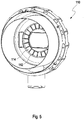
- FIG. 5 shows an interior view of a lid 110 of a housing of a filter system with rib-shaped elevations 112 in the inner cover contour 114 according to an embodiment of the invention.
- FIG. 6 is a perspective view of a secondary element 28 according to an embodiment of the invention shown.
- the second end plate of the filter element can be supported and thus introduce the force into the secondary element to press it into the housing seat and thus the unfiltered against the filtered space in the interior of the secondary element 28th seal.
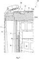
- FIG. 7 shows a section through the lid-side part of a filter system 100 according to an embodiment of the invention. It is a part of the filter element 10, consisting of filter body 12 and second end plate 18, and in the interior of the filter element 10, the housing side mounted support tube 14 and also mounted in a housing seat secondary element 28 is shown. After mounting the filter element 10 in the housing 108 and closing the lid 110 on the end face 120 presses this on the second end plate 18 via the support knobs 20. The end plate 18 presses on the other side on the end plate 18 facing the end of the support tube 14 and on the closed end 55 of the secondary element 28 with the handle 56. In the drawing, a penetration of the end plate 18 with the cover 110, the support tube 14 and the secondary element 28 is shown.
- the end plate 18 Since the material of the end plate 18 expediently polyurethane foam or a similar elastic Material is, the end plate 18 is pressed in reality between the cover 110, support tube 14 and secondary element 28 and thus transfers the force from the cover 110 to the support tube 14 and the secondary element 28. In this way, the filter element 10 is firmly clamped on the end plate 18 and thus firmly stored. In addition, the end plate 18 also presses the secondary element 28 firmly into its housing seat.
- FIG. 8 is a section through the outlet side portion 104 of a filter system according to an embodiment of the invention. It can be seen on the one hand that on the opposite end face 15 of the filter element 10 to the first end plate 16, a radial seal 26 is mounted, with the aid of which the filter element 10 seals the unfiltered against the filtered air space. On the other hand, it can be clearly seen in the section how the support tube 14 is connected to the housing 108 at the outlet end via a latching connection 60. The secondary element 28, however, is inserted into a housing seat 58 and is therefore expediently pressed into the housing seat 58 via the closed end and the second end disk of the filter element.
- FIG. 8 further shows a flexible film, which is designed as Anströmschutz.
- the film is attached to the outer periphery of the filter body 12 over the outer surface of the filter body 12 and connected along an interface, for example by means of an ultrasonic weld to form an endless, annular semi-finished and embedded in the second end plate.
Landscapes
- Engineering & Computer Science (AREA)
- Chemical & Material Sciences (AREA)
- Chemical Kinetics & Catalysis (AREA)
- Combustion & Propulsion (AREA)
- Mechanical Engineering (AREA)
- General Engineering & Computer Science (AREA)
- Manufacturing & Machinery (AREA)
- Physics & Mathematics (AREA)
- Geometry (AREA)
- Filtering Of Dispersed Particles In Gases (AREA)
Priority Applications (1)
| Application Number | Priority Date | Filing Date | Title |
|---|---|---|---|
| EP18205867.7A EP3470129B1 (de) | 2013-09-02 | 2014-08-27 | Luftfiltersystem und luftfilterelement für ein luftfiltersystem |
Applications Claiming Priority (1)
| Application Number | Priority Date | Filing Date | Title |
|---|---|---|---|
| DE102013014488.4A DE102013014488A1 (de) | 2013-09-02 | 2013-09-02 | Filtersystem und Filterelement für ein Filtersystem |
Related Child Applications (1)
| Application Number | Title | Priority Date | Filing Date |
|---|---|---|---|
| EP18205867.7A Division EP3470129B1 (de) | 2013-09-02 | 2014-08-27 | Luftfiltersystem und luftfilterelement für ein luftfiltersystem |
Publications (2)
| Publication Number | Publication Date |
|---|---|
| EP2851111A1 EP2851111A1 (de) | 2015-03-25 |
| EP2851111B1 true EP2851111B1 (de) | 2018-11-21 |
Family
ID=51662989
Family Applications (2)
| Application Number | Title | Priority Date | Filing Date |
|---|---|---|---|
| EP14182365.8A Active EP2851111B1 (de) | 2013-09-02 | 2014-08-27 | Luftfiltersystem und Verwendung eines Luftffilterelements in einem Luftffiltersystem |
| EP18205867.7A Active EP3470129B1 (de) | 2013-09-02 | 2014-08-27 | Luftfiltersystem und luftfilterelement für ein luftfiltersystem |
Family Applications After (1)
| Application Number | Title | Priority Date | Filing Date |
|---|---|---|---|
| EP18205867.7A Active EP3470129B1 (de) | 2013-09-02 | 2014-08-27 | Luftfiltersystem und luftfilterelement für ein luftfiltersystem |
Country Status (6)
| Country | Link |
|---|---|
| EP (2) | EP2851111B1 (pl) |
| CN (1) | CN104421062B (pl) |
| DE (1) | DE102013014488A1 (pl) |
| ES (1) | ES2932249T3 (pl) |
| PL (1) | PL3470129T3 (pl) |
| TR (1) | TR201901172T4 (pl) |
Families Citing this family (20)
| Publication number | Priority date | Publication date | Assignee | Title |
|---|---|---|---|---|
| ATE372162T1 (de) | 2002-10-28 | 2007-09-15 | Donaldson Co Inc | Luftfilter; auswechselbare filterpatrone; und verfahren |
| KR102439990B1 (ko) * | 2016-03-08 | 2022-09-06 | 케이앤드엔 엔지니어링, 인크. | 초-주름형 차량 공기 필터 |
| BR112019004604A2 (pt) * | 2016-09-15 | 2019-06-18 | Mahle International Gmbh | filtro de ar |
| WO2018050236A1 (en) * | 2016-09-15 | 2018-03-22 | Mahle International Gmbh | Air filter |
| WO2018050234A1 (en) | 2016-09-15 | 2018-03-22 | Mahle International Gmbh | Air filter |
| DE102016013844A1 (de) * | 2016-11-22 | 2018-05-24 | Mann + Hummel Gmbh | Rundfilterelement mit längs gestreckter Querschnittsform |
| CN115671832B (zh) * | 2017-03-20 | 2026-03-17 | 康明斯过滤Ip公司 | 带有顶部肋的内部过滤器元件的过滤器组件 |
| DE102018001183A1 (de) | 2017-04-21 | 2018-10-25 | Mann+Hummel Gmbh | Luftfilter mit geringem Druckverlust |
| US11426692B2 (en) | 2017-07-20 | 2022-08-30 | Cummins Filtration Ip, Inc. | Radial seal air filter |
| DE102018116471B4 (de) * | 2017-07-25 | 2023-06-01 | Mann+Hummel Gmbh | Filterelement und Filtersystem mit einem Filterelement |
| CN107676203B (zh) * | 2017-11-10 | 2024-01-30 | 郑良 | 初级空气滤清器 |
| CN111757776B (zh) | 2018-01-12 | 2022-01-25 | 康明斯滤清系统知识产权公司 | 易于维修的空气过滤器 |
| US12070714B2 (en) | 2018-06-07 | 2024-08-27 | Optima Pharma Containment Gmbh | Filter unit for a barrier system and barrier system, in particular isolator |
| US12172116B2 (en) | 2018-10-23 | 2024-12-24 | Cummins Filtration Ip, Inc. | Air filter assembly with a permeable baffle |
| FR3090050B1 (fr) * | 2018-12-18 | 2020-12-25 | Sogefi Filtration Spa | Filtre a air, en particulier avec un element filtrant lavable servant a verrouiller le boitier de filtre, et utilisation comme pre-filtre |
| EP3756746B1 (en) | 2019-06-27 | 2023-05-03 | MANN+HUMMEL GmbH | Filter system having a primary and a secondary filter element and secondary filter element for such a filter system |
| EP3756747A1 (en) * | 2019-06-27 | 2020-12-30 | Mann+Hummel GmbH | Filter system having a primary and a secondary filter element and primary filter element for such a filter system |
| EP3756748A1 (en) | 2019-06-27 | 2020-12-30 | Mann+Hummel GmbH | Filter system having a primary and a secondary filter element and secondary filter element for such a filter system |
| WO2021101756A1 (en) | 2019-11-18 | 2021-05-27 | Cummins Filtration Inc. | Low restriction air filter |
| WO2021211378A1 (en) | 2020-04-14 | 2021-10-21 | Cummins Filtration Inc. | Filter element with closed endcap forming a seal positioned at different axial distances |
Citations (1)
| Publication number | Priority date | Publication date | Assignee | Title |
|---|---|---|---|---|
| DE19712679A1 (de) * | 1997-03-26 | 1998-10-01 | Mann & Hummel Filter | Luftfilter |
Family Cites Families (7)
| Publication number | Priority date | Publication date | Assignee | Title |
|---|---|---|---|---|
| US4720292B1 (en) * | 1986-07-14 | 1991-09-10 | Cylindrical air filter with lightweight housing and radially directed seal | |
| DE4241586C1 (de) * | 1992-12-10 | 1994-01-27 | Mann & Hummel Filter | Luftfilter |
| DE10327441A1 (de) * | 2003-06-18 | 2005-01-05 | Daimlerchrysler Ag | Ansaugluftfilter |
| EP2086663B2 (en) * | 2006-10-06 | 2018-04-11 | Donaldson Company, Inc. | Air cleaner |
| US8066791B2 (en) * | 2007-07-20 | 2011-11-29 | Donaldson Company, Inc. | Air cleaner arrangements with internal and external support for cartridge; components; and, methods |
| DE202007013822U1 (de) | 2007-10-02 | 2009-02-19 | Mann+Hummel Gmbh | Filterelement und Filtersystem |
| DE102011120387B4 (de) * | 2010-12-15 | 2015-05-28 | Mann + Hummel Gmbh | Luftfilteranordnung und Filtervorrichtung mit einer Luftfilteranordnung |
-
2013
- 2013-09-02 DE DE102013014488.4A patent/DE102013014488A1/de not_active Ceased
-
2014
- 2014-08-27 TR TR2019/01172T patent/TR201901172T4/tr unknown
- 2014-08-27 ES ES18205867T patent/ES2932249T3/es active Active
- 2014-08-27 EP EP14182365.8A patent/EP2851111B1/de active Active
- 2014-08-27 PL PL18205867.7T patent/PL3470129T3/pl unknown
- 2014-08-27 EP EP18205867.7A patent/EP3470129B1/de active Active
- 2014-09-02 CN CN201410441258.5A patent/CN104421062B/zh active Active
Patent Citations (1)
| Publication number | Priority date | Publication date | Assignee | Title |
|---|---|---|---|---|
| DE19712679A1 (de) * | 1997-03-26 | 1998-10-01 | Mann & Hummel Filter | Luftfilter |
Also Published As
| Publication number | Publication date |
|---|---|
| EP3470129B1 (de) | 2022-10-05 |
| DE102013014488A1 (de) | 2015-03-05 |
| CN104421062B (zh) | 2019-02-12 |
| EP3470129A1 (de) | 2019-04-17 |
| EP2851111A1 (de) | 2015-03-25 |
| CN104421062A (zh) | 2015-03-18 |
| ES2932249T3 (es) | 2023-01-17 |
| PL3470129T3 (pl) | 2023-02-06 |
| TR201901172T4 (tr) | 2019-02-21 |
Similar Documents
| Publication | Publication Date | Title |
|---|---|---|
| EP2851111B1 (de) | Luftfiltersystem und Verwendung eines Luftffilterelements in einem Luftffiltersystem | |
| EP2227307B1 (de) | Filtersystem | |
| EP2742986B1 (de) | Luftfiltersystem, Luftfilterelement und Verfahren zum Austausch eines Luftfilterelements | |
| DE102014000927A1 (de) | Filterelement | |
| EP2764905A1 (de) | Filterkörper | |
| EP2765298B1 (de) | Filterelement | |
| DE102015103619A1 (de) | Vorrichtung zum Reinigen von flüssigen oder gasförmigen Medien und Abscheideelement für die Vorrichtung | |
| DE102014012948A1 (de) | Filtersystem und Filterelement für ein Filtersystem | |
| EP2851110A1 (de) | Filterelement und Filtersystem mit einem Filterelement | |
| EP2862614B2 (de) | Filtersystem mit Filterelement | |
| WO2014202450A1 (de) | Filterelement, filtergehäuse eines luftfilters und luftfilter | |
| WO2016169838A1 (de) | Sekundärelement für ein filtersystem sowie filtersystem mit einem sekundärelement | |
| EP2764904B1 (de) | Filterelement | |
| WO2008037448A1 (de) | Ringfiltereinsatz für ein filter | |
| EP2853305A1 (de) | Filterelement und Filtersystem mit einem Filterelement | |
| DE102014012579B4 (de) | Filterelement, dessen Verwendung und Filtersystem | |
| DE102014012578B4 (de) | Filtersystem und dessen Verwendung | |
| DE102013014498B4 (de) | Filterelement, dessen Verwendung und Filtersystem | |
| DE102014012947B4 (de) | Luftfiltersystem | |
| DE102014001608A1 (de) | Luftfilterelement | |
| DE102014012944A1 (de) | Filtersystem mit Filterelement | |
| DE102014014319A1 (de) | Sekundärelement für ein Filtersystem | |
| DE202013011866U1 (de) | Filterelement und Filtersystem mit einem Filterelement |
Legal Events
| Date | Code | Title | Description |
|---|---|---|---|
| PUAI | Public reference made under article 153(3) epc to a published international application that has entered the european phase |
Free format text: ORIGINAL CODE: 0009012 |
|
| 17P | Request for examination filed |
Effective date: 20140827 |
|
| AK | Designated contracting states |
Kind code of ref document: A1 Designated state(s): AL AT BE BG CH CY CZ DE DK EE ES FI FR GB GR HR HU IE IS IT LI LT LU LV MC MK MT NL NO PL PT RO RS SE SI SK SM TR |
|
| AX | Request for extension of the european patent |
Extension state: BA ME |
|
| R17P | Request for examination filed (corrected) |
Effective date: 20150414 |
|
| RBV | Designated contracting states (corrected) |
Designated state(s): AL AT BE BG CH CY CZ DE DK EE ES FI FR GB GR HR HU IE IS IT LI LT LU LV MC MK MT NL NO PL PT RO RS SE SI SK SM TR |
|
| 17Q | First examination report despatched |
Effective date: 20160802 |
|
| STAA | Information on the status of an ep patent application or granted ep patent |
Free format text: STATUS: EXAMINATION IS IN PROGRESS |
|
| GRAP | Despatch of communication of intention to grant a patent |
Free format text: ORIGINAL CODE: EPIDOSNIGR1 |
|
| STAA | Information on the status of an ep patent application or granted ep patent |
Free format text: STATUS: GRANT OF PATENT IS INTENDED |
|
| INTG | Intention to grant announced |
Effective date: 20180620 |
|
| GRAS | Grant fee paid |
Free format text: ORIGINAL CODE: EPIDOSNIGR3 |
|
| GRAA | (expected) grant |
Free format text: ORIGINAL CODE: 0009210 |
|
| STAA | Information on the status of an ep patent application or granted ep patent |
Free format text: STATUS: THE PATENT HAS BEEN GRANTED |
|
| RAP1 | Party data changed (applicant data changed or rights of an application transferred) |
Owner name: MANN + HUMMEL GMBH |
|
| AK | Designated contracting states |
Kind code of ref document: B1 Designated state(s): AL AT BE BG CH CY CZ DE DK EE ES FI FR GB GR HR HU IE IS IT LI LT LU LV MC MK MT NL NO PL PT RO RS SE SI SK SM TR |
|
| REG | Reference to a national code |
Ref country code: CH Ref legal event code: EP |
|
| REG | Reference to a national code |
Ref country code: IE Ref legal event code: FG4D Free format text: LANGUAGE OF EP DOCUMENT: GERMAN |
|
| REG | Reference to a national code |
Ref country code: DE Ref legal event code: R096 Ref document number: 502014010127 Country of ref document: DE |
|
| REG | Reference to a national code |
Ref country code: AT Ref legal event code: REF Ref document number: 1066901 Country of ref document: AT Kind code of ref document: T Effective date: 20181215 |
|
| REG | Reference to a national code |
Ref country code: NL Ref legal event code: MP Effective date: 20181121 |
|
| PG25 | Lapsed in a contracting state [announced via postgrant information from national office to epo] |
Ref country code: ES Free format text: LAPSE BECAUSE OF FAILURE TO SUBMIT A TRANSLATION OF THE DESCRIPTION OR TO PAY THE FEE WITHIN THE PRESCRIBED TIME-LIMIT Effective date: 20181121 Ref country code: IS Free format text: LAPSE BECAUSE OF FAILURE TO SUBMIT A TRANSLATION OF THE DESCRIPTION OR TO PAY THE FEE WITHIN THE PRESCRIBED TIME-LIMIT Effective date: 20190321 Ref country code: NO Free format text: LAPSE BECAUSE OF FAILURE TO SUBMIT A TRANSLATION OF THE DESCRIPTION OR TO PAY THE FEE WITHIN THE PRESCRIBED TIME-LIMIT Effective date: 20190221 Ref country code: LT Free format text: LAPSE BECAUSE OF FAILURE TO SUBMIT A TRANSLATION OF THE DESCRIPTION OR TO PAY THE FEE WITHIN THE PRESCRIBED TIME-LIMIT Effective date: 20181121 Ref country code: HR Free format text: LAPSE BECAUSE OF FAILURE TO SUBMIT A TRANSLATION OF THE DESCRIPTION OR TO PAY THE FEE WITHIN THE PRESCRIBED TIME-LIMIT Effective date: 20181121 Ref country code: BG Free format text: LAPSE BECAUSE OF FAILURE TO SUBMIT A TRANSLATION OF THE DESCRIPTION OR TO PAY THE FEE WITHIN THE PRESCRIBED TIME-LIMIT Effective date: 20190221 Ref country code: FI Free format text: LAPSE BECAUSE OF FAILURE TO SUBMIT A TRANSLATION OF THE DESCRIPTION OR TO PAY THE FEE WITHIN THE PRESCRIBED TIME-LIMIT Effective date: 20181121 Ref country code: LV Free format text: LAPSE BECAUSE OF FAILURE TO SUBMIT A TRANSLATION OF THE DESCRIPTION OR TO PAY THE FEE WITHIN THE PRESCRIBED TIME-LIMIT Effective date: 20181121 |
|
| PG25 | Lapsed in a contracting state [announced via postgrant information from national office to epo] |
Ref country code: AL Free format text: LAPSE BECAUSE OF FAILURE TO SUBMIT A TRANSLATION OF THE DESCRIPTION OR TO PAY THE FEE WITHIN THE PRESCRIBED TIME-LIMIT Effective date: 20181121 Ref country code: RS Free format text: LAPSE BECAUSE OF FAILURE TO SUBMIT A TRANSLATION OF THE DESCRIPTION OR TO PAY THE FEE WITHIN THE PRESCRIBED TIME-LIMIT Effective date: 20181121 Ref country code: SE Free format text: LAPSE BECAUSE OF FAILURE TO SUBMIT A TRANSLATION OF THE DESCRIPTION OR TO PAY THE FEE WITHIN THE PRESCRIBED TIME-LIMIT Effective date: 20181121 Ref country code: NL Free format text: LAPSE BECAUSE OF FAILURE TO SUBMIT A TRANSLATION OF THE DESCRIPTION OR TO PAY THE FEE WITHIN THE PRESCRIBED TIME-LIMIT Effective date: 20181121 Ref country code: PT Free format text: LAPSE BECAUSE OF FAILURE TO SUBMIT A TRANSLATION OF THE DESCRIPTION OR TO PAY THE FEE WITHIN THE PRESCRIBED TIME-LIMIT Effective date: 20190321 Ref country code: GR Free format text: LAPSE BECAUSE OF FAILURE TO SUBMIT A TRANSLATION OF THE DESCRIPTION OR TO PAY THE FEE WITHIN THE PRESCRIBED TIME-LIMIT Effective date: 20190222 |
|
| PG25 | Lapsed in a contracting state [announced via postgrant information from national office to epo] |
Ref country code: CZ Free format text: LAPSE BECAUSE OF FAILURE TO SUBMIT A TRANSLATION OF THE DESCRIPTION OR TO PAY THE FEE WITHIN THE PRESCRIBED TIME-LIMIT Effective date: 20181121 Ref country code: PL Free format text: LAPSE BECAUSE OF FAILURE TO SUBMIT A TRANSLATION OF THE DESCRIPTION OR TO PAY THE FEE WITHIN THE PRESCRIBED TIME-LIMIT Effective date: 20181121 Ref country code: DK Free format text: LAPSE BECAUSE OF FAILURE TO SUBMIT A TRANSLATION OF THE DESCRIPTION OR TO PAY THE FEE WITHIN THE PRESCRIBED TIME-LIMIT Effective date: 20181121 |
|
| REG | Reference to a national code |
Ref country code: DE Ref legal event code: R097 Ref document number: 502014010127 Country of ref document: DE |
|
| PG25 | Lapsed in a contracting state [announced via postgrant information from national office to epo] |
Ref country code: EE Free format text: LAPSE BECAUSE OF FAILURE TO SUBMIT A TRANSLATION OF THE DESCRIPTION OR TO PAY THE FEE WITHIN THE PRESCRIBED TIME-LIMIT Effective date: 20181121 Ref country code: SM Free format text: LAPSE BECAUSE OF FAILURE TO SUBMIT A TRANSLATION OF THE DESCRIPTION OR TO PAY THE FEE WITHIN THE PRESCRIBED TIME-LIMIT Effective date: 20181121 Ref country code: RO Free format text: LAPSE BECAUSE OF FAILURE TO SUBMIT A TRANSLATION OF THE DESCRIPTION OR TO PAY THE FEE WITHIN THE PRESCRIBED TIME-LIMIT Effective date: 20181121 Ref country code: SK Free format text: LAPSE BECAUSE OF FAILURE TO SUBMIT A TRANSLATION OF THE DESCRIPTION OR TO PAY THE FEE WITHIN THE PRESCRIBED TIME-LIMIT Effective date: 20181121 |
|
| PLBE | No opposition filed within time limit |
Free format text: ORIGINAL CODE: 0009261 |
|
| STAA | Information on the status of an ep patent application or granted ep patent |
Free format text: STATUS: NO OPPOSITION FILED WITHIN TIME LIMIT |
|
| 26N | No opposition filed |
Effective date: 20190822 |
|
| PG25 | Lapsed in a contracting state [announced via postgrant information from national office to epo] |
Ref country code: SI Free format text: LAPSE BECAUSE OF FAILURE TO SUBMIT A TRANSLATION OF THE DESCRIPTION OR TO PAY THE FEE WITHIN THE PRESCRIBED TIME-LIMIT Effective date: 20181121 |
|
| PG25 | Lapsed in a contracting state [announced via postgrant information from national office to epo] |
Ref country code: CH Free format text: LAPSE BECAUSE OF NON-PAYMENT OF DUE FEES Effective date: 20190831 Ref country code: LI Free format text: LAPSE BECAUSE OF NON-PAYMENT OF DUE FEES Effective date: 20190831 Ref country code: LU Free format text: LAPSE BECAUSE OF NON-PAYMENT OF DUE FEES Effective date: 20190827 Ref country code: MC Free format text: LAPSE BECAUSE OF FAILURE TO SUBMIT A TRANSLATION OF THE DESCRIPTION OR TO PAY THE FEE WITHIN THE PRESCRIBED TIME-LIMIT Effective date: 20181121 |
|
| REG | Reference to a national code |
Ref country code: BE Ref legal event code: MM Effective date: 20190831 |
|
| PG25 | Lapsed in a contracting state [announced via postgrant information from national office to epo] |
Ref country code: IE Free format text: LAPSE BECAUSE OF NON-PAYMENT OF DUE FEES Effective date: 20190827 |
|
| PG25 | Lapsed in a contracting state [announced via postgrant information from national office to epo] |
Ref country code: BE Free format text: LAPSE BECAUSE OF NON-PAYMENT OF DUE FEES Effective date: 20190831 |
|
| REG | Reference to a national code |
Ref country code: AT Ref legal event code: MM01 Ref document number: 1066901 Country of ref document: AT Kind code of ref document: T Effective date: 20190827 |
|
| PG25 | Lapsed in a contracting state [announced via postgrant information from national office to epo] |
Ref country code: AT Free format text: LAPSE BECAUSE OF NON-PAYMENT OF DUE FEES Effective date: 20190827 |
|
| PG25 | Lapsed in a contracting state [announced via postgrant information from national office to epo] |
Ref country code: CY Free format text: LAPSE BECAUSE OF FAILURE TO SUBMIT A TRANSLATION OF THE DESCRIPTION OR TO PAY THE FEE WITHIN THE PRESCRIBED TIME-LIMIT Effective date: 20181121 |
|
| PG25 | Lapsed in a contracting state [announced via postgrant information from national office to epo] |
Ref country code: HU Free format text: LAPSE BECAUSE OF FAILURE TO SUBMIT A TRANSLATION OF THE DESCRIPTION OR TO PAY THE FEE WITHIN THE PRESCRIBED TIME-LIMIT; INVALID AB INITIO Effective date: 20140827 Ref country code: MT Free format text: LAPSE BECAUSE OF FAILURE TO SUBMIT A TRANSLATION OF THE DESCRIPTION OR TO PAY THE FEE WITHIN THE PRESCRIBED TIME-LIMIT Effective date: 20181121 |
|
| PG25 | Lapsed in a contracting state [announced via postgrant information from national office to epo] |
Ref country code: MK Free format text: LAPSE BECAUSE OF FAILURE TO SUBMIT A TRANSLATION OF THE DESCRIPTION OR TO PAY THE FEE WITHIN THE PRESCRIBED TIME-LIMIT Effective date: 20181121 |
|
| P01 | Opt-out of the competence of the unified patent court (upc) registered |
Effective date: 20230601 |
|
| PGFP | Annual fee paid to national office [announced via postgrant information from national office to epo] |
Ref country code: DE Payment date: 20250820 Year of fee payment: 12 |
|
| PGFP | Annual fee paid to national office [announced via postgrant information from national office to epo] |
Ref country code: IT Payment date: 20250825 Year of fee payment: 12 Ref country code: TR Payment date: 20250819 Year of fee payment: 12 |
|
| PGFP | Annual fee paid to national office [announced via postgrant information from national office to epo] |
Ref country code: GB Payment date: 20250820 Year of fee payment: 12 |
|
| PGFP | Annual fee paid to national office [announced via postgrant information from national office to epo] |
Ref country code: FR Payment date: 20250829 Year of fee payment: 12 |