EP2850971A1 - Perfected hanging-bracket - Google Patents
Perfected hanging-bracket Download PDFInfo
- Publication number
- EP2850971A1 EP2850971A1 EP14183329.3A EP14183329A EP2850971A1 EP 2850971 A1 EP2850971 A1 EP 2850971A1 EP 14183329 A EP14183329 A EP 14183329A EP 2850971 A1 EP2850971 A1 EP 2850971A1
- Authority
- EP
- European Patent Office
- Prior art keywords
- bracket
- base
- screw
- hanging
- hanging bracket
- Prior art date
- Legal status (The legal status is an assumption and is not a legal conclusion. Google has not performed a legal analysis and makes no representation as to the accuracy of the status listed.)
- Granted
Links
- 230000001105 regulatory effect Effects 0.000 claims abstract description 8
- 230000008844 regulatory mechanism Effects 0.000 claims abstract description 7
- 230000007246 mechanism Effects 0.000 claims abstract description 6
- 241001661918 Bartonia Species 0.000 claims 2
- 239000002184 metal Substances 0.000 description 2
- 238000005352 clarification Methods 0.000 description 1
- 230000010355 oscillation Effects 0.000 description 1
Images
Classifications
-
- A—HUMAN NECESSITIES
- A47—FURNITURE; DOMESTIC ARTICLES OR APPLIANCES; COFFEE MILLS; SPICE MILLS; SUCTION CLEANERS IN GENERAL
- A47B—TABLES; DESKS; OFFICE FURNITURE; CABINETS; DRAWERS; GENERAL DETAILS OF FURNITURE
- A47B95/00—Fittings for furniture
- A47B95/008—Suspension fittings for cabinets to be hung on walls
-
- A—HUMAN NECESSITIES
- A47—FURNITURE; DOMESTIC ARTICLES OR APPLIANCES; COFFEE MILLS; SPICE MILLS; SUCTION CLEANERS IN GENERAL
- A47B—TABLES; DESKS; OFFICE FURNITURE; CABINETS; DRAWERS; GENERAL DETAILS OF FURNITURE
- A47B96/00—Details of cabinets, racks or shelf units not covered by a single one of groups A47B43/00 - A47B95/00; General details of furniture
- A47B96/06—Brackets or similar supporting means for cabinets, racks or shelves
- A47B96/07—Brackets or similar supporting means for cabinets, racks or shelves adjustable in themselves
Definitions
- the present invention relates to a perfected hanging bracket for the assembly of wall-cupboards, such as, for example, wall-units and base-units for kitchens and bathrooms, and other items of furniture which must be cantilever-assembled on a supporting wall.
- Metal hanging-brackets structurally consisting of a shaped base having a substantially rectangular configuration, are known.
- a bracket protruding from the base, with a hook-shaped end, is assembled on said base, in an adjustable position.
- the base is designed for being fixed to a shoulder of the wall-cupboard by fixing means, such as screws and/or pressure- or expansion- pins, or other fixing means, whereas the hook is destined for being hooked to a support - a dowel, plate, shaped bar, or similar product - fixed to the wall.
- Two regulation mechanisms cooperate with said bracket, suitable for regulating the height (vertical) and depth, respectively, of the bracket itself.
- the wall-cupboard can be assembled to a wall in the desired position, also with respect to adjacent cupboards.
- a hanging-bracket of this type is described and illustrated, for example, in international patent applications PCT/EP2009/005627 and PCT/EP2009/005628 to which reference should be made for clarifications and which should be considered as being an integral part of the present patent application.
- Hanging-brackets of the type briefly described above are fixed to the shoulder of the piece of furniture, either manually or using an automated assembly line equipped with a vibrating feeder, which serves for feeding the hanging-bracket in the correct position, to the automatic fixing unit of the same to the shoulder of the cupboard.
- the vibration of the vibrating feeder tends to tighten or loosen (depending on the rotation direction, clockwise or anticlockwise, of the vibrating feeder) the regulation screws of the height and depth of the above-mentioned mechanisms with which the hanging-bracket is equipped.
- An objective of the present invention is to overcome the above drawback of the known art, by providing a hanging-bracket with regulation mechanisms of the height and depth, equipped with regulation screws whose position can in no way be accidentally modified by the vibrations of a vibrating feeder, or similar tool.
- a metal hanging-bracket produced according to the invention is indicated as a whole with 20 and is structurally composed of a shaped base or shell 21, having a substantially rectangular configuration, on which a bracket 22 is assembled in an adjustable position (with the possibility of rotation and translation).
- said bracket 22 comprises two opposite sides or flanks 23, which envelop the base 21, protruding from the latter with a hook-shaped end 24.
- Two regulation mechanisms cooperate with said bracket 22, a first 25 for regulating the height, a second 26 for regulating the depth.
- the hanging-bracket thus structured is fixed to the shoulder of the cupboard, for example by means of self-threading screws (not shown) which pass through holes 27 of the base 21.
- the hook 24 is suitable for being hooked to a support fixed to the wall, for example a dowel, a plate, a bar, or equivalent means.
- the first height (vertical) regulation mechanism 25 comprises a lunette 28 guided to slide on the base 21.
- the lower end of said lunette 28 acts on the bracket 22, whereas the upper end cooperates with a regulation screw 29 which is screwed onto a nut 30 blocked on the base 21.
- Said screw 29 has a head 31 with an imprint for an operating tool.
- the stem of the screw 29 is supported by means of arched supports 32 of the base 21.
- the second mechanism for regulating the depth 26 consists of a regulation screw 33 acting on the end of the bracket 22 opposite the hook 24.
- Said screw 33 is screwed onto a nut 34 blocked on the bracket 22.
- the stem of the screw 33 is supported by the bracket 22 and by an arched support 35 of the base 21, said support 35, together with end teeth 39 of the base 21 itself, defining a containment seat 40 for the head 41, with an imprint 42, of the screw 33.
- an undesired accidental rotation (screwing or unscrewing) of the screws 29 and 33 - caused, for example, by a vibrating feeder - is prevented, by completely pulling the bracket 22 against the base (21) by tightening the screw 33: this maneuver compels the bracket 22 to acquire the horizontal position illustrated in figures 1 and 2 of the drawings.
- the screw 29 cannot be screwed (as it is pushing the lunette 28 and consequently the bracket 22, which is blocked in a horizontal position by the tightening of the screw 33) and cannot be unscrewed (as, thanks to a deformation d in its threading which is engaged with the nut 30, it creates friction with the rotation which prevents the same).
- the deformation d is obtained by means of a punch 36 and a counter-punch 37 between which the hanging-bracket 20 is positioned.
- FIGs 12, 13 show a hanging-bracket completely identical to that illustrated in figures 1-11 , with the exception of the fixing means to the shoulder of the cupboard; pressure pins 38 (so-called doubels) are in fact envisaged instead of holes 27 for screws.
Abstract
Description
- The present invention relates to a perfected hanging bracket for the assembly of wall-cupboards, such as, for example, wall-units and base-units for kitchens and bathrooms, and other items of furniture which must be cantilever-assembled on a supporting wall.
- Metal hanging-brackets structurally consisting of a shaped base having a substantially rectangular configuration, are known.
- A bracket protruding from the base, with a hook-shaped end, is assembled on said base, in an adjustable position.
- The base is designed for being fixed to a shoulder of the wall-cupboard by fixing means, such as screws and/or pressure- or expansion- pins, or other fixing means, whereas the hook is destined for being hooked to a support - a dowel, plate, shaped bar, or similar product - fixed to the wall.
- Two regulation mechanisms cooperate with said bracket, suitable for regulating the height (vertical) and depth, respectively, of the bracket itself.
- The wall-cupboard can be assembled to a wall in the desired position, also with respect to adjacent cupboards.
- A hanging-bracket of this type is described and illustrated, for example, in international patent applications
PCT/EP2009/005627 PCT/EP2009/005628 - Hanging-brackets of the type briefly described above, are fixed to the shoulder of the piece of furniture, either manually or using an automated assembly line equipped with a vibrating feeder, which serves for feeding the hanging-bracket in the correct position, to the automatic fixing unit of the same to the shoulder of the cupboard.
- As is well-known to experts in the field, the vibration of the vibrating feeder tends to tighten or loosen (depending on the rotation direction, clockwise or anticlockwise, of the vibrating feeder) the regulation screws of the height and depth of the above-mentioned mechanisms with which the hanging-bracket is equipped.
- This is a serious drawback, as said regulation screws of the height and depth of the hanging-bracket, translate and acquire a position which is different from that established by the manufacturer of the hanging-bracket for a correct use of the same, for both manual or automatic fixing of the same to the shoulder of the cupboard, and also for a simple, correct and rapid assembly of the cupboard to the support fixed to the wall.
- An objective of the present invention is to overcome the above drawback of the known art, by providing a hanging-bracket with regulation mechanisms of the height and depth, equipped with regulation screws whose position can in no way be accidentally modified by the vibrations of a vibrating feeder, or similar tool.
- This objective is achieved by a hanging-bracket having the characteristics specified in
claim 1 and enclosed sub-claims. - The structural and functional characteristics of the invention and its advantages with respect to the known art will appear clearly understandable from the following description referring to the enclosed drawings, which illustrate embodiment examples of the invention itself.
- In the drawings:
-
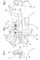
Figure 1 is a raised view taken according to the arrow A offigure 4 ; -
Figure 2 is a raised view taken according to the arrow B offigure 4 ; -
Figure 3 is a raised view taken according to the arrow C offigure 1 ; -
Figure 4 is a raised view taken according to the arrow D offigure 1 ; -
Figure 5 is a plan view taken according to the arrow E offigure 1 ; -
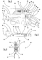
Figures 6 and 7 are two perspective views illustrating the hanging-bracket offigures 1-5 ; -
Figure 8 is a sectional view taken according to the line VIII-VIII offigure 1 ; -
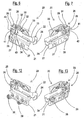
Figures 9, 10 and 11 are enlarged sectional details illustrating processing phases of the hanging-bracket according to the invention; and -
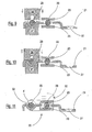
Figures 12 and 13 are perspective views similar tofigures 6 and 7 , illustrating the same hanging-bracket equipped with different means for fixing it to the shoulder of the piece of furniture. - With particular reference to
figures 1-8 of the drawings, a metal hanging-bracket produced according to the invention is indicated as a whole with 20 and is structurally composed of a shaped base orshell 21, having a substantially rectangular configuration, on which abracket 22 is assembled in an adjustable position (with the possibility of rotation and translation). - As can be clearly seen from the drawings, said
bracket 22 comprises two opposite sides orflanks 23, which envelop thebase 21, protruding from the latter with a hook-shaped end 24. - Two regulation mechanisms cooperate with said
bracket 22, a first 25 for regulating the height, asecond 26 for regulating the depth. - The hanging-bracket thus structured is fixed to the shoulder of the cupboard, for example by means of self-threading screws (not shown) which pass through
holes 27 of thebase 21. - The
hook 24, on the other hand, is suitable for being hooked to a support fixed to the wall, for example a dowel, a plate, a bar, or equivalent means. - More specifically, the first height (vertical)
regulation mechanism 25 comprises alunette 28 guided to slide on thebase 21. The lower end of saidlunette 28 acts on thebracket 22, whereas the upper end cooperates with aregulation screw 29 which is screwed onto anut 30 blocked on thebase 21. - Said screw 29 has a
head 31 with an imprint for an operating tool. The stem of thescrew 29 is supported by means ofarched supports 32 of thebase 21. - The second mechanism for regulating the
depth 26 consists of aregulation screw 33 acting on the end of thebracket 22 opposite thehook 24. - Said
screw 33 is screwed onto anut 34 blocked on thebracket 22. The stem of thescrew 33 is supported by thebracket 22 and by anarched support 35 of thebase 21, saidsupport 35, together withend teeth 39 of thebase 21 itself, defining acontainment seat 40 for thehead 41, with animprint 42, of thescrew 33. - From the above description with reference to
Figures 1-7 , and as is well-known to experts in the field, once the cupboard has been assembled to the wall, the rotation of the height-regulation screw 29 will cause an oscillation around thearea 43 of thebracket 22 in the direction of the arrow F, whereas a rotation of the depth-regulation screw 33 will cause a translation of thesame arm 22 in the direction of the arrow F1. - The functioning of the height and depth regulation mechanisms of the hanging-bracket in question is also illustrated and described in detail in the above-mentioned international patent applications
PCT/ EP2009/005627 PCT/EP2009/005628 - According to the invention, an undesired accidental rotation (screwing or unscrewing) of the
screws 29 and 33 - caused, for example, by a vibrating feeder - is prevented, by completely pulling thebracket 22 against the base (21) by tightening the screw 33: this maneuver compels thebracket 22 to acquire the horizontal position illustrated infigures 1 and2 of the drawings. With thebracket 22 in an exactly horizontal position, thescrew 29 cannot be screwed (as it is pushing thelunette 28 and consequently thebracket 22, which is blocked in a horizontal position by the tightening of the screw 33) and cannot be unscrewed (as, thanks to a deformation d in its threading which is engaged with thenut 30, it creates friction with the rotation which prevents the same). - Said deformation d in the threading of the
screw 29 can be clearly seen in the enlargement offigure 11 . - As can be clearly seen in
figures 9 and 10 , the deformation d is obtained by means of apunch 36 and acounter-punch 37 between which the hanging-bracket 20 is positioned. -
Figures 12, 13 show a hanging-bracket completely identical to that illustrated infigures 1-11 , with the exception of the fixing means to the shoulder of the cupboard; pressure pins 38 (so-called doubels) are in fact envisaged instead ofholes 27 for screws. - The objective indicated in the preamble of the description, has therefore been achieved.
- The protection scope of the invention is defined by the following claims.
Claims (9)
- A perfected hanging bracket (20) for the assembly of wall-cupboards of the type comprising, in combination:a shaped base (21) on which a bracket (22) is assembled, whose position is adjustable, with the possibility of rotating and translating, said bracket (22) having a hook-shaped end (24) protruding from said base (21), two regulation mechanisms, the first (25) for adjusting the height and a second (26) for adjusting the depth, cooperating with said bracket (22), the first mechanism (25) for regulating the height comprises a lunette (28) guided to slide on the base (21), the lower end of said lunette (28) acting on the bracket (22) whereas the upper end cooperates with a regulation screw (29), the second mechanism (26) for regulating the depth, consists of a regulation screw (33) which acts on the end of the bracket (22) opposite to the hook (24), characterized in that an undesired accidental rotation (screwing or unscrewing) of said screws (29) and (33) is prevented by completely pulling the bracket (22) against the base (21) by tightening the screw (33), said manoeuvre compelling the bracket (22) to acquire a horizontal position, the screw (29) cannot therefore be screwed by pushing the lunette (28) and consequently the bracket (22), which is blocked in a horizontal position by the tightening of the screw (33) and cannot be unscrewed as, thanks to a deformation (d) in its threading, it creates friction with the rotation which prevents it.
- The hanging bracket according to claim 1, characterized in that said regulation screw (29) is screwed onto a nut (30) blocked on the base (21).
- The hanging bracket according to claim 1, characterized in that said regulation screw (33) is screwed onto a nut (34) blocked on the bracket (22).
- The hanging bracket according to claim 1, characterized in that said bracket (22) comprises two opposite sides (23), which enclose the base (21) and protrude from the latter by means of said hook-shaped end (24).
- The hanging bracket according to claim 1, characterized in that the screw stem (29) is supported by means of arched supports (32) of the base (21).
- The hanging bracket according to claim 1, characterized in that the screw stem (33) is supported by the bracket (22) and by an arched support (35) of the base (21), and said support (35), together with terminal teeth (39) of the same base (21), defines a containment seat (40) for a head (41) of said screw (33).
- The hanging bracket according to claim 1, characterized in that said base (21) has holes (27) for the passage of fixing screws of the hanging bracket to the shoulder of the piece of furniture.
- The hanging bracket according to claim 1, characterized in that said base (21) has pins (38) for fixing the hanging bracket to the shoulder of the piece of furniture.
- The hanging bracket according to claim 1, characterized in that said base (21) has a substantially rectangular configuration.
Applications Claiming Priority (1)
| Application Number | Priority Date | Filing Date | Title |
|---|---|---|---|
| IT001546A ITMI20131546A1 (en) | 2013-09-19 | 2013-09-19 | PERFECT FIBERGLASS |
Publications (2)
| Publication Number | Publication Date |
|---|---|
| EP2850971A1 true EP2850971A1 (en) | 2015-03-25 |
| EP2850971B1 EP2850971B1 (en) | 2016-04-27 |
Family
ID=49585513
Family Applications (1)
| Application Number | Title | Priority Date | Filing Date |
|---|---|---|---|
| EP14183329.3A Active EP2850971B1 (en) | 2013-09-19 | 2014-09-03 | Process to prevent an accidental rotation of adjustment screws of a hanging bracket |
Country Status (5)
| Country | Link |
|---|---|
| EP (1) | EP2850971B1 (en) |
| ES (1) | ES2583062T3 (en) |
| IT (1) | ITMI20131546A1 (en) |
| PL (1) | PL2850971T3 (en) |
| RU (1) | RU2654446C2 (en) |
Cited By (1)
| Publication number | Priority date | Publication date | Assignee | Title |
|---|---|---|---|---|
| CN111182817A (en) * | 2017-10-03 | 2020-05-19 | 莱昂纳多有限责任公司 | Hidden tear-resistant suspension bracket assembly with accurate depth adjustment |
Citations (3)
| Publication number | Priority date | Publication date | Assignee | Title |
|---|---|---|---|---|
| DE9102703U1 (en) * | 1991-03-07 | 1991-05-23 | Paul Hettich Gmbh & Co, 4983 Kirchlengern, De | |
| WO2010012503A1 (en) * | 2008-07-29 | 2010-02-04 | Leonardo S.R.L. | Adjustable wall cupboard holder group for anchoring a cupboard to the wall |
| WO2010121687A1 (en) * | 2009-04-24 | 2010-10-28 | Leonardo S.R.L. | Release preventing system for wall cupboards |
Family Cites Families (4)
| Publication number | Priority date | Publication date | Assignee | Title |
|---|---|---|---|---|
| SU1498669A1 (en) * | 1987-04-06 | 1989-08-07 | Предприятие П/Я А-7460 | Device for storing piece cargoes |
| DE102006032227A1 (en) * | 2006-07-07 | 2008-01-10 | Rieber Gmbh & Co. Kg | Mobile field/camping cooker has an intermediate base for the burners and a working surface dimensioned to take standard cooking pots |
| DE202007006355U1 (en) * | 2007-05-03 | 2008-07-10 | OCé PRINTING SYSTEMS GMBH | Transport crate for transporting high-quality, heavy goods |
| DE202013101802U1 (en) * | 2013-04-25 | 2014-07-28 | Delbrouck Gmbh | transport case |
-
2013
- 2013-09-19 IT IT001546A patent/ITMI20131546A1/en unknown
-
2014
- 2014-09-03 ES ES14183329.3T patent/ES2583062T3/en active Active
- 2014-09-03 PL PL14183329.3T patent/PL2850971T3/en unknown
- 2014-09-03 EP EP14183329.3A patent/EP2850971B1/en active Active
- 2014-09-11 RU RU2014136799A patent/RU2654446C2/en active
Patent Citations (3)
| Publication number | Priority date | Publication date | Assignee | Title |
|---|---|---|---|---|
| DE9102703U1 (en) * | 1991-03-07 | 1991-05-23 | Paul Hettich Gmbh & Co, 4983 Kirchlengern, De | |
| WO2010012503A1 (en) * | 2008-07-29 | 2010-02-04 | Leonardo S.R.L. | Adjustable wall cupboard holder group for anchoring a cupboard to the wall |
| WO2010121687A1 (en) * | 2009-04-24 | 2010-10-28 | Leonardo S.R.L. | Release preventing system for wall cupboards |
Cited By (2)
| Publication number | Priority date | Publication date | Assignee | Title |
|---|---|---|---|---|
| CN111182817A (en) * | 2017-10-03 | 2020-05-19 | 莱昂纳多有限责任公司 | Hidden tear-resistant suspension bracket assembly with accurate depth adjustment |
| CN111182817B (en) * | 2017-10-03 | 2022-02-11 | 莱昂纳多有限责任公司 | Hidden tear-resistant suspension bracket assembly with accurate depth adjustment |
Also Published As
| Publication number | Publication date |
|---|---|
| RU2654446C2 (en) | 2018-05-17 |
| PL2850971T3 (en) | 2016-10-31 |
| ITMI20131546A1 (en) | 2015-03-20 |
| ES2583062T3 (en) | 2016-09-16 |
| EP2850971B1 (en) | 2016-04-27 |
| RU2014136799A (en) | 2016-04-10 |
Similar Documents
| Publication | Publication Date | Title |
|---|---|---|
| EP2557963B1 (en) | A hooking device for hooking a drawer to a longitudinal guide | |
| RU2661118C2 (en) | Pincer nail correction instrument | |
| EP2215373B1 (en) | Speed nut | |
| US20120146476A1 (en) | Tolerance adaptive slide connection assemblies | |
| RU2512872C2 (en) | Fittings | |
| EP3457890B1 (en) | Automatically activated anti-disengagement system for a hidden hanging bracket for wall cupboards | |
| EP2850971B1 (en) | Process to prevent an accidental rotation of adjustment screws of a hanging bracket | |
| US20080226417A1 (en) | Spring Nut | |
| RU2008133651A (en) | DEVICE FOR FASTENING FACE PANELS OF DRAWERS | |
| US2651483A (en) | Typewriter retaining bracket | |
| RU2016150702A (en) | HIDDEN MOUNTING RACK HOLDER WITH AN IMPROVED DISCONNECTION PREVENTION SYSTEM FOR WALL CABINETS | |
| US9683357B2 (en) | System and method for installing an undermount sink | |
| JP2017532070A (en) | Visible hanging bracket for wall cabinet with improved detachment prevention system | |
| JP2008133641A (en) | Pull handle device and cabinet equipped with the same | |
| ES2727504B2 (en) | Flange adjustable to the thickness of the flange of an elevator guide | |
| JP6148890B2 (en) | Faucet mounting device | |
| EP2947232B1 (en) | Wall system of coating panels and hanging brackets with a vertical regulation device | |
| EP2149316B1 (en) | Improved mounting device for hanging furniture | |
| AU2015252163A1 (en) | Device for the tool-free mounting of modules on a top-hat rail and for the destruction-free, tool-free unmounting of the same | |
| JP2002017454A (en) | Leg length adjustor for desk, etc. | |
| KR101437099B1 (en) | Support bar assembly for hanger and mounting piece | |
| US20180115091A1 (en) | Battery clamp and method for manufacturing a battery clamp | |
| US20170089381A1 (en) | Fastening device for fastening an object to a wall, and fastening system | |
| JP2007282705A (en) | Device for fixing display hook | |
| JP2016116321A (en) | Fastening fixture |
Legal Events
| Date | Code | Title | Description |
|---|---|---|---|
| PUAI | Public reference made under article 153(3) epc to a published international application that has entered the european phase |
Free format text: ORIGINAL CODE: 0009012 |
|
| 17P | Request for examination filed |
Effective date: 20140903 |
|
| AK | Designated contracting states |
Kind code of ref document: A1 Designated state(s): AL AT BE BG CH CY CZ DE DK EE ES FI FR GB GR HR HU IE IS IT LI LT LU LV MC MK MT NL NO PL PT RO RS SE SI SK SM TR |
|
| AX | Request for extension of the european patent |
Extension state: BA ME |
|
| R17P | Request for examination filed (corrected) |
Effective date: 20150709 |
|
| RBV | Designated contracting states (corrected) |
Designated state(s): AL AT BE BG CH CY CZ DE DK EE ES FI FR GB GR HR HU IE IS IT LI LT LU LV MC MK MT NL NO PL PT RO RS SE SI SK SM TR |
|
| GRAP | Despatch of communication of intention to grant a patent |
Free format text: ORIGINAL CODE: EPIDOSNIGR1 |
|
| INTG | Intention to grant announced |
Effective date: 20151112 |
|
| RIN1 | Information on inventor provided before grant (corrected) |
Inventor name: CATTANEO, CARLO |
|
| GRAS | Grant fee paid |
Free format text: ORIGINAL CODE: EPIDOSNIGR3 |
|
| GRAA | (expected) grant |
Free format text: ORIGINAL CODE: 0009210 |
|
| AK | Designated contracting states |
Kind code of ref document: B1 Designated state(s): AL AT BE BG CH CY CZ DE DK EE ES FI FR GB GR HR HU IE IS IT LI LT LU LV MC MK MT NL NO PL PT RO RS SE SI SK SM TR |
|
| REG | Reference to a national code |
Ref country code: GB Ref legal event code: FG4D |
|
| REG | Reference to a national code |
Ref country code: CH Ref legal event code: EP |
|
| REG | Reference to a national code |
Ref country code: AT Ref legal event code: REF Ref document number: 793775 Country of ref document: AT Kind code of ref document: T Effective date: 20160515 |
|
| REG | Reference to a national code |
Ref country code: IE Ref legal event code: FG4D |
|
| REG | Reference to a national code |
Ref country code: DE Ref legal event code: R096 Ref document number: 602014001702 Country of ref document: DE |
|
| REG | Reference to a national code |
Ref country code: LT Ref legal event code: MG4D |
|
| REG | Reference to a national code |
Ref country code: NL Ref legal event code: MP Effective date: 20160427 |
|
| REG | Reference to a national code |
Ref country code: ES Ref legal event code: FG2A Ref document number: 2583062 Country of ref document: ES Kind code of ref document: T3 Effective date: 20160916 |
|
| REG | Reference to a national code |
Ref country code: FR Ref legal event code: PLFP Year of fee payment: 3 |
|
| PG25 | Lapsed in a contracting state [announced via postgrant information from national office to epo] |
Ref country code: NL Free format text: LAPSE BECAUSE OF FAILURE TO SUBMIT A TRANSLATION OF THE DESCRIPTION OR TO PAY THE FEE WITHIN THE PRESCRIBED TIME-LIMIT Effective date: 20160427 |
|
| PG25 | Lapsed in a contracting state [announced via postgrant information from national office to epo] |
Ref country code: FI Free format text: LAPSE BECAUSE OF FAILURE TO SUBMIT A TRANSLATION OF THE DESCRIPTION OR TO PAY THE FEE WITHIN THE PRESCRIBED TIME-LIMIT Effective date: 20160427 Ref country code: LT Free format text: LAPSE BECAUSE OF FAILURE TO SUBMIT A TRANSLATION OF THE DESCRIPTION OR TO PAY THE FEE WITHIN THE PRESCRIBED TIME-LIMIT Effective date: 20160427 Ref country code: NO Free format text: LAPSE BECAUSE OF FAILURE TO SUBMIT A TRANSLATION OF THE DESCRIPTION OR TO PAY THE FEE WITHIN THE PRESCRIBED TIME-LIMIT Effective date: 20160727 |
|
| PG25 | Lapsed in a contracting state [announced via postgrant information from national office to epo] |
Ref country code: LV Free format text: LAPSE BECAUSE OF FAILURE TO SUBMIT A TRANSLATION OF THE DESCRIPTION OR TO PAY THE FEE WITHIN THE PRESCRIBED TIME-LIMIT Effective date: 20160427 Ref country code: SE Free format text: LAPSE BECAUSE OF FAILURE TO SUBMIT A TRANSLATION OF THE DESCRIPTION OR TO PAY THE FEE WITHIN THE PRESCRIBED TIME-LIMIT Effective date: 20160427 Ref country code: RS Free format text: LAPSE BECAUSE OF FAILURE TO SUBMIT A TRANSLATION OF THE DESCRIPTION OR TO PAY THE FEE WITHIN THE PRESCRIBED TIME-LIMIT Effective date: 20160427 Ref country code: PT Free format text: LAPSE BECAUSE OF FAILURE TO SUBMIT A TRANSLATION OF THE DESCRIPTION OR TO PAY THE FEE WITHIN THE PRESCRIBED TIME-LIMIT Effective date: 20160829 Ref country code: HR Free format text: LAPSE BECAUSE OF FAILURE TO SUBMIT A TRANSLATION OF THE DESCRIPTION OR TO PAY THE FEE WITHIN THE PRESCRIBED TIME-LIMIT Effective date: 20160427 Ref country code: GR Free format text: LAPSE BECAUSE OF FAILURE TO SUBMIT A TRANSLATION OF THE DESCRIPTION OR TO PAY THE FEE WITHIN THE PRESCRIBED TIME-LIMIT Effective date: 20160728 |
|
| PG25 | Lapsed in a contracting state [announced via postgrant information from national office to epo] |
Ref country code: BE Free format text: LAPSE BECAUSE OF FAILURE TO SUBMIT A TRANSLATION OF THE DESCRIPTION OR TO PAY THE FEE WITHIN THE PRESCRIBED TIME-LIMIT Effective date: 20160427 |
|
| REG | Reference to a national code |
Ref country code: DE Ref legal event code: R097 Ref document number: 602014001702 Country of ref document: DE |
|
| PG25 | Lapsed in a contracting state [announced via postgrant information from national office to epo] |
Ref country code: DK Free format text: LAPSE BECAUSE OF FAILURE TO SUBMIT A TRANSLATION OF THE DESCRIPTION OR TO PAY THE FEE WITHIN THE PRESCRIBED TIME-LIMIT Effective date: 20160427 Ref country code: EE Free format text: LAPSE BECAUSE OF FAILURE TO SUBMIT A TRANSLATION OF THE DESCRIPTION OR TO PAY THE FEE WITHIN THE PRESCRIBED TIME-LIMIT Effective date: 20160427 Ref country code: RO Free format text: LAPSE BECAUSE OF FAILURE TO SUBMIT A TRANSLATION OF THE DESCRIPTION OR TO PAY THE FEE WITHIN THE PRESCRIBED TIME-LIMIT Effective date: 20160427 Ref country code: CZ Free format text: LAPSE BECAUSE OF FAILURE TO SUBMIT A TRANSLATION OF THE DESCRIPTION OR TO PAY THE FEE WITHIN THE PRESCRIBED TIME-LIMIT Effective date: 20160427 Ref country code: SK Free format text: LAPSE BECAUSE OF FAILURE TO SUBMIT A TRANSLATION OF THE DESCRIPTION OR TO PAY THE FEE WITHIN THE PRESCRIBED TIME-LIMIT Effective date: 20160427 |
|
| PG25 | Lapsed in a contracting state [announced via postgrant information from national office to epo] |
Ref country code: SM Free format text: LAPSE BECAUSE OF FAILURE TO SUBMIT A TRANSLATION OF THE DESCRIPTION OR TO PAY THE FEE WITHIN THE PRESCRIBED TIME-LIMIT Effective date: 20160427 |
|
| PLBE | No opposition filed within time limit |
Free format text: ORIGINAL CODE: 0009261 |
|
| STAA | Information on the status of an ep patent application or granted ep patent |
Free format text: STATUS: NO OPPOSITION FILED WITHIN TIME LIMIT |
|
| 26N | No opposition filed |
Effective date: 20170130 |
|
| PG25 | Lapsed in a contracting state [announced via postgrant information from national office to epo] |
Ref country code: MC Free format text: LAPSE BECAUSE OF FAILURE TO SUBMIT A TRANSLATION OF THE DESCRIPTION OR TO PAY THE FEE WITHIN THE PRESCRIBED TIME-LIMIT Effective date: 20160427 |
|
| PG25 | Lapsed in a contracting state [announced via postgrant information from national office to epo] |
Ref country code: SI Free format text: LAPSE BECAUSE OF FAILURE TO SUBMIT A TRANSLATION OF THE DESCRIPTION OR TO PAY THE FEE WITHIN THE PRESCRIBED TIME-LIMIT Effective date: 20160427 |
|
| REG | Reference to a national code |
Ref country code: IE Ref legal event code: MM4A |
|
| PG25 | Lapsed in a contracting state [announced via postgrant information from national office to epo] |
Ref country code: IE Free format text: LAPSE BECAUSE OF NON-PAYMENT OF DUE FEES Effective date: 20160903 |
|
| PG25 | Lapsed in a contracting state [announced via postgrant information from national office to epo] |
Ref country code: LU Free format text: LAPSE BECAUSE OF NON-PAYMENT OF DUE FEES Effective date: 20160903 |
|
| REG | Reference to a national code |
Ref country code: FR Ref legal event code: PLFP Year of fee payment: 4 |
|
| REG | Reference to a national code |
Ref country code: CH Ref legal event code: PL |
|
| PG25 | Lapsed in a contracting state [announced via postgrant information from national office to epo] |
Ref country code: HU Free format text: LAPSE BECAUSE OF FAILURE TO SUBMIT A TRANSLATION OF THE DESCRIPTION OR TO PAY THE FEE WITHIN THE PRESCRIBED TIME-LIMIT; INVALID AB INITIO Effective date: 20140903 |
|
| PG25 | Lapsed in a contracting state [announced via postgrant information from national office to epo] |
Ref country code: MT Free format text: LAPSE BECAUSE OF NON-PAYMENT OF DUE FEES Effective date: 20160930 Ref country code: CY Free format text: LAPSE BECAUSE OF FAILURE TO SUBMIT A TRANSLATION OF THE DESCRIPTION OR TO PAY THE FEE WITHIN THE PRESCRIBED TIME-LIMIT Effective date: 20160427 Ref country code: MK Free format text: LAPSE BECAUSE OF FAILURE TO SUBMIT A TRANSLATION OF THE DESCRIPTION OR TO PAY THE FEE WITHIN THE PRESCRIBED TIME-LIMIT Effective date: 20160427 Ref country code: IS Free format text: LAPSE BECAUSE OF FAILURE TO SUBMIT A TRANSLATION OF THE DESCRIPTION OR TO PAY THE FEE WITHIN THE PRESCRIBED TIME-LIMIT Effective date: 20160427 |
|
| PG25 | Lapsed in a contracting state [announced via postgrant information from national office to epo] |
Ref country code: LI Free format text: LAPSE BECAUSE OF NON-PAYMENT OF DUE FEES Effective date: 20170930 Ref country code: BG Free format text: LAPSE BECAUSE OF FAILURE TO SUBMIT A TRANSLATION OF THE DESCRIPTION OR TO PAY THE FEE WITHIN THE PRESCRIBED TIME-LIMIT Effective date: 20160427 Ref country code: CH Free format text: LAPSE BECAUSE OF NON-PAYMENT OF DUE FEES Effective date: 20170930 |
|
| REG | Reference to a national code |
Ref country code: AT Ref legal event code: UEP Ref document number: 793775 Country of ref document: AT Kind code of ref document: T Effective date: 20160427 |
|
| REG | Reference to a national code |
Ref country code: FR Ref legal event code: PLFP Year of fee payment: 5 |
|
| PG25 | Lapsed in a contracting state [announced via postgrant information from national office to epo] |
Ref country code: TR Free format text: LAPSE BECAUSE OF FAILURE TO SUBMIT A TRANSLATION OF THE DESCRIPTION OR TO PAY THE FEE WITHIN THE PRESCRIBED TIME-LIMIT Effective date: 20160427 Ref country code: AL Free format text: LAPSE BECAUSE OF FAILURE TO SUBMIT A TRANSLATION OF THE DESCRIPTION OR TO PAY THE FEE WITHIN THE PRESCRIBED TIME-LIMIT Effective date: 20160427 |
|
| P01 | Opt-out of the competence of the unified patent court (upc) registered |
Effective date: 20230610 |
|
| PGFP | Annual fee paid to national office [announced via postgrant information from national office to epo] |
Ref country code: GB Payment date: 20230927 Year of fee payment: 10 Ref country code: AT Payment date: 20230821 Year of fee payment: 10 |
|
| PGFP | Annual fee paid to national office [announced via postgrant information from national office to epo] |
Ref country code: PL Payment date: 20230822 Year of fee payment: 10 Ref country code: FR Payment date: 20230925 Year of fee payment: 10 Ref country code: DE Payment date: 20230927 Year of fee payment: 10 |
|
| PGFP | Annual fee paid to national office [announced via postgrant information from national office to epo] |
Ref country code: ES Payment date: 20231002 Year of fee payment: 10 |
|
| PGFP | Annual fee paid to national office [announced via postgrant information from national office to epo] |
Ref country code: IT Payment date: 20230925 Year of fee payment: 10 |