JP6148890B2 - Faucet mounting device - Google Patents
Faucet mounting device Download PDFInfo
- Publication number
- JP6148890B2 JP6148890B2 JP2013082413A JP2013082413A JP6148890B2 JP 6148890 B2 JP6148890 B2 JP 6148890B2 JP 2013082413 A JP2013082413 A JP 2013082413A JP 2013082413 A JP2013082413 A JP 2013082413A JP 6148890 B2 JP6148890 B2 JP 6148890B2
- Authority
- JP
- Japan
- Prior art keywords
- hole
- male screw
- fixing member
- main body
- faucet
- Prior art date
- Legal status (The legal status is an assumption and is not a legal conclusion. Google has not performed a legal analysis and makes no representation as to the accuracy of the status listed.)
- Active
Links
Images


Landscapes
- Domestic Plumbing Installations (AREA)
- Dowels (AREA)
Description
本発明は、シンクやカウンター等の天板に形成されている取付孔に対して、上側から水栓を取付けるために用いられる水栓取付装置に関する。 The present invention relates to a faucet attachment device used for attaching a faucet from above to an attachment hole formed in a top plate such as a sink or a counter.
シンクやカウンター等の天板に形成されている取付孔に対して、上側から水栓を取付けるための水栓取付装置としては、例えば、水栓が取付けられる円筒状の台座と、台座の下側に配置される円環状の座金具と、上側から台座を通して座金具に接続されている可撓性を有した連結材と、台座の貫通孔を通して座金具のネジ孔に締結可能な雄ネジ部材と、を備えた水栓取付装置が提案されている(特許文献1)。 The faucet attachment device for attaching the faucet from the upper side to the attachment hole formed in the top plate of the sink or counter, for example, is a cylindrical pedestal to which the faucet is attached, and the lower side of the pedestal An annular seat fitting disposed on the top, a flexible connecting member connected to the seat fitting from the upper side through the pedestal, and a male screw member that can be fastened to the screw hole of the seat fitting through the through hole of the pedestal Have been proposed (Patent Document 1).
この特許文献1の水栓取付装置は、円環状の座金具が半円弧状に折り畳むことができ、座金具を折り畳んだ状態で、天板の取付孔に上側から座金具を挿入し、天板の下側で折り畳んだ座金具を展開させると共に、連結材により座金具を引上げて天板の下面に密着させ、台座の貫通孔を通して座金具のネジ孔に雄ネジ部材を締結する。これにより、台座と座金具とによって天板が挟持され、天板の上側に台座が固定された状態となる。そして、天板の上側に固定された台座に水栓を取付けることによって、取付孔に対して上側から水栓を取付けることができる。
In the faucet mounting device of
ところで、特許文献1の水栓取付装置では、折り畳んだ座金具を、取付孔を通して天板の下側で展開させなければならず、座金具の展開に手間がかかる問題があった。これに対して、この折り畳み可能な円環状の座金具を、馬蹄形状に形成された挟み込み部材に置き換え、挟み込み部材の一方の先端から取付孔に挿入して天板の下側へ位置させることができるようにした水栓取付装置が提案されている(特許文献2)。
By the way, in the faucet attachment apparatus of
しかしながら、特許文献1及び特許文献2の水栓取付装置では、取付孔を通して天板の下側に配置した座金具や挟み込み部材に対して、台座の貫通孔を通して座金具等のネジ孔に雄ネジ部材を締結させる際に、座金具等を引上げる連結材が可撓性を有しているため、台座の貫通孔と座金具等のネジ孔との位置が合わせ難く、雄ネジ部材の締結作業、つまり、台座の固定作業に手間がかかる問題があった。
However, in the faucet mounting devices of
そこで、本発明は上記の実情に鑑み、シンクやカウンター等の天板の取付孔に対して上側から容易に固定することが可能な水栓取付装置の提供を課題とする。 In view of the above circumstances, an object of the present invention is to provide a faucet mounting device that can be easily fixed from above to a mounting hole of a top plate such as a sink or a counter.
上記の課題を解決するために、本発明に係る水栓取付装置は、「水栓が取付けられる円筒状の上本体部、該上本体部の内周面から膨出していると共に下面が該上本体部の下面よりも下方へ突出している一対の膨出部、前記上本体部の下端外周面から外方へ延出している円環状のフランジ部、一対の前記膨出部の一方において上下に貫通している第一貫通孔、及び該第一貫通孔が貫通している前記膨出部とは異なる該膨出部を上下に貫通している第二貫通孔を有している上固定部材と、該上固定部材の前記第一貫通孔が貫通している前記膨出部において前記第一貫通孔に隣接した位置から下方へ延出しており、外周が多角形に形成されている棒状のガイド部材と、前記第一貫通孔よりも大径の第一頭部、該第一頭部から下方へ棒状に延びており外径が前記第一貫通孔よりも小径で外周に雄ネジが形成されている第一雄ネジ部、及び該第一雄ネジ部の外径よりも外方へ延出している延出部、を有しており、前記第一頭部よりも下側が前記第一貫通孔に挿入されていると共に、前記第一頭部を前記上本体部の上面に当接させた時に下端が前記ガイド部材の下端と略同じ高さとなる長さに形成されている第一雄ネジ部材と、前記第二貫通孔よりも大径の第二頭部、該第二頭部から下方へ棒状に延びており外径が前記第二貫通孔よりも小径で外周に雄ネジが形成されている第二雄ネジ部、及び該第二雄ネジ部の下端から下方へ向うに従って径が小さくなる円錐台状の突起部、を有しており、前記第二頭部よりも下側が前記第二貫通孔に挿入されている第二雄ネジ部材と、平面視の外形がC字状に形成されている下本体部、該下本体部を上下に貫通しており前記ガイド部材が摺動可能且つ回転不能に挿入されているガイド孔、前記下本体部を上下に貫通しており内周面に前記第一雄ネジ部と螺合する雌ネジが形成されている第一雌ネジ孔、及び前記下本体部を上下に貫通しており内周面に前記第二雄ネジ部と螺合する雌ネジが形成されている第二雌ネジ孔、を有しており、前記ガイド孔に前記ガイド部材を挿通させることにより、上下方向の軸周りに回転不能とされる下固定部材とを具備している」ことを特徴とする。 In order to solve the above-described problems, the faucet mounting device according to the present invention includes a cylindrical upper body portion to which a faucet is attached, a bulge from an inner peripheral surface of the upper body portion, and a lower surface of the upper body portion. A pair of bulging portions projecting downward from the lower surface of the main body portion, an annular flange portion extending outward from the outer peripheral surface of the lower end of the upper main body portion, and one of the pair of bulging portions vertically An upper fixing member having a first through hole penetrating through and a second through hole vertically penetrating through the bulging portion different from the bulging portion through which the first through hole penetrates And a bar-like shape that extends downward from a position adjacent to the first through-hole in the bulging portion through which the first through-hole of the upper fixing member passes, and whose outer periphery is formed in a polygonal shape. A guide member, a first head having a diameter larger than that of the first through hole, and extending downward from the first head in a bar shape A first male screw portion having a diameter smaller than that of the first through-hole and having a male screw formed on the outer periphery, and an extending portion extending outward from the outer diameter of the first male screw portion, And the lower side of the first head is inserted into the first through hole, and the lower end of the guide member is brought into contact with the upper surface of the upper main body. substantially a first male threaded member which is formed at the same height as the become long and the bottom end, the second head of larger diameter than the second through hole, the outer extends in a rod shape from said second head downward A second male screw portion having a diameter smaller than that of the second through hole and having a male screw formed on the outer periphery thereof, and a truncated cone-shaped protrusion that decreases in diameter as it goes downward from the lower end of the second male screw portion the has, the second and the second male thread member the lower is inserted into the second through-hole than the head, the C-shaped profile in plan view A lower main body formed, a guide hole penetrating the lower main body up and down and the guide member being slidably and non-rotatably inserted; an inner circumference passing through the lower main body up and down A first female screw hole in which a female screw to be screwed with the first male screw part is formed on the surface, and the lower main body part are vertically penetrated and screwed with the second male screw part on the inner peripheral surface. second female screw hole female screw is formed to have a, wherein by inserting the guide member in the guide hole, and a lower fixing member that will be unable to rotate around the vertical axis "
ここで、「多角形」としては、四角形、六角形、等を例示することができる。また、「延出部」としては、軸部に対して着脱自在としても良いし、軸部に取外し不能とされていても良い。 Here, examples of the “polygon” include a quadrangle, a hexagon, and the like. In addition, the “extending portion” may be detachable from the shaft portion, or may not be removable from the shaft portion.
本発明の水栓取付装置は、シンクやカウンター等の天板の水栓を取付ける位置において、上本体部を貫通している第一貫通孔及び第二貫通孔が臨む内径の取付孔に対して、上側から固定することができる。具体的には、まず、第二雄ネジ部材を上固定部材から外し、第一貫通孔に挿入されている第一雄ネジ部材の第一頭部を上本体部の上面に当接させると共に、第一雄ネジ部材の下端の延出部に下固定部材を当接させた状態とする。これにより、上固定部材からガイド部材と第一雄ネジ部材が隣接した状態で下方へ延出していると共に、それらガイド部材と第一雄ネジ部材の下端に下固定部材が位置し、上固定部材に対して下固定部材が最も離れた状態となる。 The faucet mounting device according to the present invention has a first through hole penetrating the upper main body portion and an inner diameter mounting hole facing the second through hole at a position where a faucet of a top plate such as a sink or a counter is mounted. Can be fixed from above. Specifically, first, the second male screw member is removed from the upper fixing member, the first head of the first male screw member inserted into the first through hole is brought into contact with the upper surface of the upper main body part, The lower fixing member is brought into contact with the extended portion at the lower end of the first male screw member. As a result, the guide member and the first male screw member extend downward from the upper fixing member, and the lower fixing member is positioned at the lower ends of the guide member and the first male screw member. The lower fixing member is in the most distant state.
この状態で、天板の取付孔に上側から下固定部材を傾けた状態で挿入し、天板の下側に下固定部材を位置させてから、天板に上固定部材を載置する。そして、第一雄ネジ部材を上方へ移動させることにより、第一雄ネジ部材の下端の延出部に当接している下固定部材を、第一雄ネジ部材と共に上昇させ、下固定部材を天板の下面に当接させる。この際に、ガイド部材が、下固定部材のガイド孔に摺動可能且つ回転不能に挿入されていることから、下固定部材は上下に延びた軸周りに対して回転することなく上昇する。つまり、下固定部材は、その第二雌ネジ孔が、上固定部材の第二貫通孔に対して同軸上に位置したままの状態で上昇する。 In this state, the lower fixing member is inserted into the mounting hole of the top plate in an inclined state from the upper side, the lower fixing member is positioned on the lower side of the top plate, and then the upper fixing member is placed on the top plate. Then, by moving the first male screw member upward, the lower fixing member in contact with the extending portion at the lower end of the first male screw member is raised together with the first male screw member, and the lower fixing member is It contacts the lower surface of the plate. At this time, since the guide member is inserted into the guide hole of the lower fixing member so as to be slidable and non-rotatable, the lower fixing member rises without rotating around the axis extending vertically. That is, the lower fixing member ascends with the second female screw hole positioned coaxially with respect to the second through hole of the upper fixing member.
そして、下固定部材を天板の下面に当接させた状態で、上固定部材の第二貫通孔に上側から第二雄ネジ部材の第二雄ネジ部を挿入して、第二雄ネジ部材を締め付ける方向へ回転させると、第二雄ネジ部が下固定部材の第二雌ネジ孔と螺合することとなる。この状態で第二雄ネジ部材を締め付けることにより、第二雄ネジ部材側において上固定部材と下固定部材とで天板が挟まれた状態で締結される。 Then, with the lower fixing member in contact with the lower surface of the top plate, the second male screw member of the second male screw member is inserted from above into the second through hole of the upper fixing member, and the second male screw member Is rotated in the tightening direction, the second male screw portion is screwed into the second female screw hole of the lower fixing member. By tightening the second male screw member in this state, the second male screw member is fastened with the top plate sandwiched between the upper fixing member and the lower fixing member.
その後、第一雄ネジ部材を締め付ける方向へ回転させて第一雄ネジ部材を締め付けることにより、第一雄ネジ部材側においても上固定部材と下固定部材とで天板が挟まれた状態で締結される。これにより、天板に水栓取付装置が固定された状態となり、この水栓取付装置の上固定部材に水栓を取付けることにより、天板に水栓を取付けることができる。 After that, by rotating the first male screw member in the tightening direction and tightening the first male screw member, the top male plate is fastened with the upper fixing member and the lower fixing member sandwiched on the first male screw member side. Is done. Thus, the faucet attachment device is fixed to the top plate, and the faucet can be attached to the top plate by attaching the faucet to the upper fixing member of the faucet attachment device.
このように、本発明の水栓取付装置によれば、天板に形成されている取付孔に対して、上側から下固定部材を挿入させた上で、第一雄ネジ部材を介して上方へ移動させて天板の下面に当接させるだけで、上固定部材の第二貫通孔と、下固定部材の第二雌ネジ孔とを一致させることができるため、第二雄ネジ部材を第二雌ネジ孔へ簡単に螺合させることができ、水栓取付装置を天板の取付孔に対して上側から容易に固定することができる。 Thus, according to the faucet mounting device of the present invention, the lower fixing member is inserted into the mounting hole formed in the top plate from above, and then upward through the first male screw member. Since the second through hole of the upper fixing member and the second female screw hole of the lower fixing member can be made to coincide with each other simply by moving and contacting the lower surface of the top plate, the second male screw member can be It can be easily screwed into the female screw hole, and the faucet attachment device can be easily fixed to the attachment hole of the top plate from above.
本発明の水栓取付装置によれば、円筒状の上本体部の内側に第一貫通孔や第二貫通孔、及びガイド部材が配置されることとなるため、第一貫通孔や第二貫通孔を上本体部の円筒部分で貫通させるようにした場合と比較して、上本体部の外径を同じとした場合、上本体部の内径(内側の広さ)を相対的に大きくすることができる。従って、水栓の下端から下方へ延出している供給管を、筒状の上本体部に対して通し易くすることができ、水栓の取付作業を行い易くすることができる。 According to the faucet mounting device of the present invention, since the first through hole, the second through hole, and the guide member are arranged inside the cylindrical upper main body, the first through hole and the second through hole are arranged. Compared to the case where the hole is made to penetrate through the cylindrical portion of the upper main body, the inner diameter (inside width) of the upper main body is relatively increased when the outer diameter of the upper main body is the same. Can do. Accordingly, the supply pipe extending downward from the lower end of the faucet can be easily passed through the cylindrical upper main body, and the faucet can be easily attached.
また、本発明に係る水栓取付装置は、上記の構成に加えて、「前記第一雄ネジ部材は、前記第一雄ネジ部の下端から下方へ棒状に延びており外径が該第一雄ネジ部よりも小径の軸部を更に有しており、該軸部の下端に前記延出部が備えられている」ことを特徴としても良い。 In addition to the above-described configuration, the faucet mounting device according to the present invention may include: “The first male screw member extends downward from the lower end of the first male screw portion in a bar shape and has an outer diameter of the first male screw member. It further includes a shaft portion having a smaller diameter than the male screw portion, and the extension portion is provided at the lower end of the shaft portion.
ところで、第一雄ネジ部や第二雄ネジ部の長さとしては、本発明の水栓取付装置が固定される天板の厚さに対して、下固定部材の厚さ(上下方向の高さ)を加えた長さが少なくとも必要である。これら第一雄ネジ部等が最小限の長さの場合では、天板に固定する前の上固定部材と下固定部材との間が狭くなるため、下固定部材を取付孔に挿入しようとすると、上固定部材が天板に当ってしまい、取付孔に挿入させることができなくなる問題がある。そこで、第一雄ネジ部等を充分に長くして上固定部材から下固定部材が遠く離れるようにすることにより、下固定部材を取付孔に挿入させる時に上固定部材が天板に当らないようにして、取付孔へ挿入させられるようにすることが考えられる。しかしながら、第一雄ネジ部等を充分に長くした場合、第一雌ネジ孔や第二雌ネジ孔に螺合させて締め付ける際に、第一雄ネジ部材や第二雄ネジ部材を回転させる回数が必要以上に多くなり、固定作業に手間がかかる問題が生じる。 By the way, as for the length of the first male screw portion and the second male screw portion, the thickness of the lower fixing member (the height in the vertical direction) is larger than the thickness of the top plate to which the faucet mounting device of the present invention is fixed. At least the length added). In the case where these first male threaded portions have a minimum length, the space between the upper fixing member and the lower fixing member before being fixed to the top plate becomes narrow, so when trying to insert the lower fixing member into the mounting hole There is a problem that the upper fixing member hits the top plate and cannot be inserted into the mounting hole. Therefore, by making the first male screw part long enough so that the lower fixing member is far away from the upper fixing member, the upper fixing member does not hit the top plate when the lower fixing member is inserted into the mounting hole. Thus, it is conceivable to make it possible to insert into the mounting hole. However, when the first male screw part is sufficiently long, the number of times the first male screw member or the second male screw member is rotated when screwed into the first female screw hole or the second female screw hole and tightened. There is a problem that the amount of fixing becomes more than necessary and the fixing work is troublesome.
これに対して、本発明では、第一雄ネジ部材の第一雄ネジ部の下端に小径の軸部を備えると共に、その軸部の下端に延出部を備えているため、例えば、第一雄ネジ部の長さを必要最小限の長さとした場合、軸部の下端に下固定部材を位置させることにより上固定部材から下固定部材を充分に離すことができ、下固定部材を取付孔へ挿入し易くすることができると共に、第一雄ネジ部材により締結させる際に、第一雄ネジ部材を回転させる回数を必要最小限にすることができ、固定作業にかかる手間を少なくすることができる。 On the other hand, in the present invention, since a small-diameter shaft portion is provided at the lower end of the first male screw portion of the first male screw member and an extension portion is provided at the lower end of the shaft portion, for example, the first When the length of the male screw part is the minimum necessary length, the lower fixing member can be sufficiently separated from the upper fixing member by positioning the lower fixing member at the lower end of the shaft part. When the first male screw member is fastened, the number of rotations of the first male screw member can be minimized and the time required for fixing work can be reduced. it can.
このように、本発明によれば、シンクやカウンター等の天板の取付孔に対して上側から容易に固定することが可能な水栓取付装置を提供できる。 Thus, according to the present invention, it is possible to provide a faucet attachment device that can be easily fixed from above to the attachment holes of the top plate such as a sink or a counter.
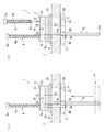
本発明の一実施形態である水栓取付装置1について、図1及び図2を参照して詳細に説明する。本実施形態の水栓取付装置1は、シンクやカウンター等の天板Tに形成されている取付孔Hに、上側から水栓Sを取付けるために用いられる。水栓取付装置1は、水栓Sが取付けられると共に天板Tの上側に取付孔Hを覆うように載置される上固定部材2と、天板Tを挟んで上固定部材2の下側に配置される下固定部材3と、天板Tを挟んで上固定部材2と下固定部材3とを締結する第一雄ネジ部材4及び第二雄ネジ部材5と、上固定部材2から下固定部材3を貫通して下方へ延出する六角柱状のガイド部材6と、を備えている。図1では、水栓Sとして湯水混合水栓を記載しており、水栓Sの下端から水側と湯側の二つの供給管S1が下方へ延出している。
A
上固定部材2は、水栓Sが取付けられる円筒状の上本体部2aと、上本体部2aの下端外周面から外方へ延出している円環状のフランジ部2bと、上本体部2aの内周面において周方向の一部から膨出している第一膨出部2cと、第一膨出部2cとは上本体部2aの内周面において周方向の異なる位置から膨出している第二膨出部2dと、第一膨出部2cを上下に貫通している第一貫通孔2eと、第二膨出部2dを上下に貫通している第二貫通孔2fと、を備えている。また、上固定部材2は、上本体部2aの外周面の下部において内周側へ凹んでいる環状の保持溝2gと、上本体部2aの外周面を貫通していると共に内面に雌ネジが形成されている水栓固定孔2hと、を備えている。
The
上固定部材2は、円筒状の上本体部2aの内径が、天板Tの取付孔Hの内径と略同じに形成されている。また、フランジ部2bの外径は、取付孔Hよりも大径に形成されている。第一膨出部2c及び第二膨出部2dは、上面が上本体部2aの上面よりも下方へ窪んでいる。また、第一膨出部2c及び第二膨出部2dは、下面が、上本体部2aの下面よりも下方へ突出している。詳細な図示は省略するが、第一膨出部2c及び第二膨出部2dは、上本体部2aの図1において左右方向の中心を通る線に対して対称に形成されていると共に、上本体部2aの中心よりも図1において紙面の奥側に夫々形成されている。これにより、水栓Sから下方へ延びている供給管S1を、上本体部2a内を貫通させるためのスペースが確保されている。本実施形態では、図1において左側を第一膨出部2c、右側を第二膨出部2dとしている。
The
第一貫通孔2e及び第二貫通孔2fは、第一膨出部2c及び第二膨出部2dにおいて可及的に互いに遠ざかった位置に形成されている。第一膨出部2cでは、その下面の第一貫通孔2eに隣接した位置にガイド部材6の上端側が固定されている。これにより、第一膨出部2cからガイド部材6が下方へ延出した状態となる。保持溝2gには、上本体部2aの外周と水栓Sの下端内周との間のガタツキを防止するためのゴム等の弾性体からなるOリング7が装着保持される。
The first through
下固定部材3は、平面視の外形がC字状に形成されている下本体部3aと、下本体部3aを上下に貫通しており内周面に同じ雌ネジが形成されている第一雌ネジ孔3b及び第二雌ネジ孔3cと、第一雌ネジ孔3bに隣接した位置で下本体部3aを上下に貫通しておりガイド部材6が挿入されているガイド孔3dと、を備えている。また、下固定部材3は、上面の全面に上端が尖った複数の突部3eを備えている。下固定部材3は、上下の高さが、上固定部材2の高さの約1/2に形成されている。本実施形態では、図1において左側を第一雌ネジ孔3b、右側を第二雌ネジ孔3cとしている。
The
下固定部材3の下本体部3aは、C字状の外周側が、上固定部材2のフランジ部2bの外径よりも大径の円弧状に形成されている。また、下本体部3aは、C字状の内周側が、上固定部材2の上本体部2aと第一膨出部2c及び第二膨出部2dとで形成されている内周形状の一部と略同じ形状に形成されている。第一雌ネジ孔3b及び第二雌ネジ孔3cは、平面視において上固定部材2の第一貫通孔2e及び第二貫通孔2fと同じ位置に形成されている。
The lower
ガイド孔3dは、内周形状がガイド部材6の外周形状よりも若干大きい六角柱形状に形成されている。これにより、ガイド孔3dがガイド部材6を挿入させた状態では、ガイド部材6の長手方向へは相対的に移動(摺動)させることができるものの、ガイド部材6の軸芯周りには回転不能である。
The
第一雄ネジ部材4は、上固定部材2の第一貫通孔2eよりも大径の第一頭部4aと、第一頭部4aから下方へ棒状に延びており外径が貫通孔2dよりも小径で外周に雄ネジが形成されている第一雄ネジ部4bと、第一雄ネジ部4bの下端から下方へ棒状に延びており外径が第一雄ネジ部4bよりも小径の軸部4cと、及び軸部4cの下端から第一雄ネジ部4bの外径よりも外方へ延出している延出部4d、を備えている。
The first male screw member 4 has a
第一雄ネジ部材4の第一雄ネジ部4bは、下固定部材3の第一雌ネジ孔3bの雌ネジと螺合する雄ネジが形成されている。この第一雄ネジ部4bは、その軸方向の長さが、上本体部2aの内径(取付孔Hの直径)の約2倍に形成されている。軸部4cは、外周面が滑らかな円柱状に形成されている。また、軸部4cは、その軸方向の長さが、第一雄ネジ部4bの長さの約1/2に形成されている。延出部4dは、図2(b)に示すように、本実施形態では、Eリングとされており、軸部4cの外周下端に形成されている溝4eに着脱自在に取付けられている。
The first
第一雄ネジ部材4は、延出部4dを取外した状態とすることにより、上固定部材2の第一貫通孔2eや下固定部材3の第一雌ネジ孔3bに、第一雄ネジ部4bや軸部4cを挿通させることができる。また、貫通孔2dや第一雌ネジ孔3bに、第一雄ネジ部4bや軸部4cを挿通した状態で、延出部4dを取付けることにより、第一貫通孔2eや第一雌ネジ孔3b等から抜けないようにすることができる。
The first male screw member 4 is in a state in which the extending
第二雄ネジ部材5は、上固定部材2の第二貫通孔2fよりも大径の第二頭部5aと、第二頭部5aから下方へ棒状に延びており外径が貫通孔2dよりも小径で外周に雄ネジが形成されている第二雄ネジ部5bと、第二雄ネジ部5bの下端から下方へ向うに従って径が小さくなる円錐台状の突起部5cと、を備えている。
The second
第二雄ネジ部材5の第二雄ネジ部5bは、下固定部材3の第二雌ネジ孔3cの雌ネジと螺合する雄ネジが形成されている。この第二雄ネジ部5bは、軸方向の長さが、第一雄ネジ部4bの長さと同じに形成されている。
The second
ガイド部材6は、棒状で外周が六角形に形成されており、下端に下方へ向うに従って径が小さくなる円錐台状の突起部6aを備えている。このガイド部材6は、水栓取付装置1を天板Tの取付孔Hに固定した状態で、その下端が第一雄ネジ部材4の下端と略おなじ高さとなる長さに形成されている。
The
本実施形態の水栓取付装置1は、真鍮やステンレス、亜鉛ダイカスト等の耐食性に優れた金属によって形成されている。
The
次に、本実施形態の水栓取付装置1を天板Tの取付孔Hに上側から固定する方法を、主に図3乃至図5を参照して説明する。水栓取付装置1は、上固定部材2の第一膨出部2c及び第二膨出部2dにおいて上本体部2aから下方へ突出している部分を挿入することができる大きさの取付孔Hに取付けることができ、第一膨出部2c及び第二膨出部2dの下方へ突出している部分の外周径よりも若干大きい径の取付孔Hに取付けることができる。この水栓取付装置1は、取付孔Hに固定する前の状態では、第二雄ネジ部材5が上固定部材2から取外されており、上固定部材2の第一貫通孔2eに挿入されている第一雄ネジ部材4とガイド部材6に、下固定部材3が挿通されている。また、上固定部材2の下面に、薄い円環状のパッキン8が貼り付けられている(図1等を参照)。このパッキン8により、上固体部材2と天板Tとの間を水密にシールすることができる他、上固定部材2と天板Tとのガタツキをなくすことができ、上固定部材2を介して水栓Sを安定した状態に取付けることができる。
Next, a method for fixing the
固定する前の状態で、第一雄ネジ部材4の第一頭部4aを第一膨出部2cの上面に当接させると共に、第一雄ネジ部材4の下端の延出部4dに下固定部材3を当接させた状態とする(図2において第二雄ネジ部材5を外した状態)。これにより、上固定部材2に対して下固定部材3が最も離れた状態となる。
In a state before being fixed, the
この状態で、下固定部材3において第二雌ネジ孔3c側の端部から天板Tの取付孔Hに挿入されるように全体を傾けて、天板Tの上側から取付孔Hに下固定部材3を挿入し(図3(a)を参照)、天板Tの下側に下固定部材3を位置させてから、天板Tに上固定部材2を載置する(図3(b)を参照)。この際に、上固定部材2において第一膨出部2c及び第二膨出部2dの上本体部2aから下方へ突出している部位を、取付孔H内に挿入させた後に、上固定部材2を天板Tの上面に沿って移動させて、取付孔Hの軸芯と上固定部材2の軸芯とを合わせる。
In this state, the
上固定部材2を天板Tに載置したら、次に、第一雄ネジ部材4を上方へ移動させることにより、第一雄ネジ部材4の下端の延出部4dに当接している下固定部材3を、第一雄ネジ部材4と共に上昇させ、下固定部材3を天板Tの下面に当接させる(図4(c)を参照)。この際に、ガイド部材6が、下固定部材3のガイド孔3dに摺動可能且つ回転不能に挿入されていることから、下固定部材3は上下に延びた軸周りに対して回転することなく上昇する。つまり、下固定部材3は、その第二雌ネジ孔3cが、上固定部材2の第二膨出部2dの第二貫通孔2fに対して同軸上に位置したままの状態で上昇する。
After the upper fixing
そして、下固定部材3を天板Tの下面に当接させた状態で、上固定部材2の第二貫通孔2fに上側から第二雄ネジ部材5の第二雄ネジ部5bを挿入させて(図4(d)を参照)、上固定部材2を貫通させた上で、その下端を下固定部材3の第二雌ネジ孔3cに挿入させる。この際に、第二雄ネジ部材5の下端には、突起部5cが備えられているため、第二雄ネジ部材5の下端を第二雌ネジ孔3cへ容易に挿入させることができる。そして、第二雄ネジ部材5を締め付ける方向へ回転させると、第二雄ネジ部5が下固定部材3の第二雌ネジ孔3cと螺合することとなる。そして、第二雄ネジ部材5を締め付けることにより、第二雄ネジ部材5側において上固定部材2と下固定部材3とで天板Tが挟まれた状態で締結される(図5(e)を参照)。
Then, with the
その後、第一雄ネジ部材4を下降させて、第一雄ネジ部4bの下端を下固定部材3の第一雌ネジ孔3bに挿入させると共に、第一雄ネジ部材4を締め付ける方向へ回転させることにより、第一雄ネジ部材4の第一雄ネジ部4bが下固定部材3の第一雌ネジ孔3bと螺合することとなる。そして、第一雄ネジ部材4を締め付けることにより、第一雄ネジ部材4側においても上固定部材2と下固定部材3とで天板Tが挟まれた状態で締結される(図5(f)を参照)。
Thereafter, the first male screw member 4 is lowered, the lower end of the first
これら第一雄ネジ部材4及び第二雄ネジ部材5の締め付けにより、下固定部材3の複数の突部3eが、天板Tの下面に突き刺さり、下固定部材3が天板Tの面に沿った方向へ動くのが規制される。従って、天板Tの取付孔Hに対して水栓取付装置1が位置不動に固定された状態となる。
By tightening the first male screw member 4 and the second
天板Tの取付孔Hに水栓取付装置1を固定したら、上固定部材2の保持溝2gにOリング7を装着保持させる。その後、取付ける水栓Sの下端から延びている二つの供給管S1を、上固定部材2における上本体部2aの筒内の空きスペース及び取付孔Hを通して、天板Tの下側へ延出させる。そして、水栓Sの下端に上固定部材2の上本体部2aを挿入させた上で、水栓Sの外側から図示しないビスを上固定部材2の水栓固定孔2fに捩じ込むことにより、水栓Sが天板Tに取付けられる(図1を参照)。
When the
このように、本実施形態の水栓取付装置1によれば、ガイド部材6によって下固定部材3を回動不能としており、上固定部材2の第二貫通孔2fと、下固定部材3の第二雌ネジ孔3cとを一致させることができるため、第二雄ネジ部材5を第二雌ネジ孔3cへ簡単に螺合させることができ、水栓取付装置1を天板Tの取付孔Hに対して上側から容易に固定することができる。
Thus, according to the
また、第一雄ネジ部材4の第一雄ネジ部4bの下端に小径の軸部4cを備えているため、例えば、第一雄ネジ部4bの長さを必要最小限の長さとした場合、軸部4cの下端に下固定部材3を位置させることにより上固定部材2から下固定部材3を充分に離れるようにすることができ、下固定部材3を取付孔Hへ挿入し易くすることができると共に、第一雄ネジ部材4により締結させる際に、第一雄ネジ部材4を回転させる回数を必要最小限にすることができ、固定作業にかかる手間を少なくすることができる。
Moreover, since the small-
更に、第二雄ネジ部材5の下端に突起部5cを備えているため、ガタツキ等によって第二雄ネジ部5bの下端の中心が第二雌ネジ孔3cの中心とずれてしまっても、下端の突起部5cが第二雌ネジ孔3cに挿入されることにより、その下端の中心を第二雌ネジ孔3cの中心へ誘導することができ、第二雌ネジ孔3cに対して第二雄ネジ部5bを容易に螺合させることができる。
Furthermore, since the
以上、本発明について好適な実施形態を挙げて説明したが、本発明は上記の実施形態に限定されるものではなく、以下に示すように、本発明の要旨を逸脱しない範囲において、種々の改良及び設計の変更が可能である。 The present invention has been described with reference to the preferred embodiments. However, the present invention is not limited to the above-described embodiments, and various improvements can be made without departing from the scope of the present invention as described below. And design changes are possible.
例えば、上記の実施形態では、第一雄ネジ部材5の突起部5cとして、着脱自在なEリングとしたものを示したが、これに限定するものではなく、カシメ加工やバーリング加工等により取外し不能な突起部5cとしても良い。
For example, in the above-described embodiment, the
1 水栓取付装置
2 上固定部材
2a 上本体部
2b フランジ部
2c 第一膨出部
2d 第二膨出部
2e 第一貫通孔
2f 第二貫通孔
3 下固定部材
3a 下本体部
3b 第一雌ネジ孔
3c 第二雌ネジ孔
3d ガイド孔
3e 突部
4 第一雄ネジ部材
4a 第一頭部
4b 第一雄ネジ部
4c 軸部
4d 延出部
4e 溝
5 第二雄ネジ部材
5a 第二頭部
5b 第二雄ネジ部
5c 突起部
6 ガイド部材
T 天板
H 取付孔
S 水栓
DESCRIPTION OF
Claims (2)
該上固定部材の前記第一貫通孔が貫通している前記膨出部において前記第一貫通孔に隣接した位置から下方へ延出しており、外周が多角形に形成されている棒状のガイド部材と、
前記第一貫通孔よりも大径の第一頭部、該第一頭部から下方へ棒状に延びており外径が前記第一貫通孔よりも小径で外周に雄ネジが形成されている第一雄ネジ部、及び該第一雄ネジ部の外径よりも外方へ延出している延出部、を有しており、前記第一頭部よりも下側が前記第一貫通孔に挿入されていると共に、前記第一頭部を前記上本体部の上面に当接させた時に下端が前記ガイド部材の下端と略同じ高さとなる長さに形成されている第一雄ネジ部材と、
前記第二貫通孔よりも大径の第二頭部、該第二頭部から下方へ棒状に延びており外径が前記第二貫通孔よりも小径で外周に雄ネジが形成されている第二雄ネジ部、及び該第二雄ネジ部の下端から下方へ向うに従って径が小さくなる円錐台状の突起部、を有しており、前記第二頭部よりも下側が前記第二貫通孔に挿入されている第二雄ネジ部材と、
平面視の外形がC字状に形成されている下本体部、該下本体部を上下に貫通しており前記ガイド部材が摺動可能且つ回転不能に挿入されているガイド孔、前記下本体部を上下に貫通しており内周面に前記第一雄ネジ部と螺合する雌ネジが形成されている第一雌ネジ孔、及び前記下本体部を上下に貫通しており内周面に前記第二雄ネジ部と螺合する雌ネジが形成されている第二雌ネジ孔、を有しており、前記ガイド孔に前記ガイド部材を挿通させることにより、上下方向の軸周りに回転不能とされる下固定部材と
を具備していることを特徴とする水栓取付装置。 A cylindrical upper main body portion to which a water faucet is attached , a pair of bulged portions that bulge from the inner peripheral surface of the upper main body portion and whose lower surface protrudes downward from the lower surface of the upper main body portion, the upper main body An annular flange portion extending outward from the outer peripheral surface of the lower end of the portion, a first through hole penetrating vertically in one of the pair of bulging portions , and the first through hole are penetrating An upper fixing member having a second through hole penetrating up and down the bulging portion different from the bulging portion ;
A bar-shaped guide member that extends downward from a position adjacent to the first through-hole in the bulging portion through which the first through-hole of the upper fixing member passes and has a polygonal outer periphery When,
A first head having a diameter larger than that of the first through-hole, a rod extending downward from the first head, an outer diameter being smaller than that of the first through-hole, and a male screw formed on the outer periphery. A first male screw portion and an extending portion extending outward from the outer diameter of the first male screw portion, and the lower side of the first head is inserted into the first through hole. And a first male screw member formed such that the lower end is substantially the same height as the lower end of the guide member when the first head is brought into contact with the upper surface of the upper main body part,
The is the second head of larger diameter, the male screw on the outer periphery with a diameter smaller than the outer diameter extends in a rod shape downwardly from the second head said second through-hole is formed than the second through hole A second male screw portion, and a truncated cone-shaped protruding portion whose diameter decreases as it goes downward from the lower end of the second male screw portion, and the lower side of the second head is the second through hole. A second male screw member inserted into
Lower body part having a C-shaped outer shape in plan view, a guide hole penetrating vertically through the lower body part, and the guide member being slidably and non-rotatably inserted therein, the lower body part The first female screw hole in which an internal thread is formed on the inner peripheral surface of the first male screw portion, and the lower main body portion is formed on the inner peripheral surface. A second female screw hole in which a female screw is formed to be screwed with the second male screw part, and the guide member is inserted into the guide hole so that it cannot rotate around the vertical axis. faucet mounting apparatus characterized in that it comprises a lower fixing member that will be the.
前記第一雄ネジ部の下端から下方へ棒状に延びており外径が該第一雄ネジ部よりも小径の軸部を更に有しており、
該軸部の下端に前記延出部が備えられていることを特徴とする請求項1に記載の水栓取付装置。 The first male screw member is
The first male screw part further extends from the lower end of the first male screw part downward and has a shaft part whose outer diameter is smaller than that of the first male screw part,
The faucet mounting device according to claim 1 , wherein the extending portion is provided at a lower end of the shaft portion .
Priority Applications (1)
| Application Number | Priority Date | Filing Date | Title |
|---|---|---|---|
| JP2013082413A JP6148890B2 (en) | 2013-04-10 | 2013-04-10 | Faucet mounting device |
Applications Claiming Priority (1)
| Application Number | Priority Date | Filing Date | Title |
|---|---|---|---|
| JP2013082413A JP6148890B2 (en) | 2013-04-10 | 2013-04-10 | Faucet mounting device |
Publications (3)
| Publication Number | Publication Date |
|---|---|
| JP2014205950A JP2014205950A (en) | 2014-10-30 |
| JP2014205950A5 JP2014205950A5 (en) | 2016-04-07 |
| JP6148890B2 true JP6148890B2 (en) | 2017-06-14 |
Family
ID=52119727
Family Applications (1)
| Application Number | Title | Priority Date | Filing Date |
|---|---|---|---|
| JP2013082413A Active JP6148890B2 (en) | 2013-04-10 | 2013-04-10 | Faucet mounting device |
Country Status (1)
| Country | Link |
|---|---|
| JP (1) | JP6148890B2 (en) |
Families Citing this family (2)
| Publication number | Priority date | Publication date | Assignee | Title |
|---|---|---|---|---|
| CN109024781A (en) * | 2018-09-28 | 2018-12-18 | 厦门大锦工贸有限公司 | The faucet and its installation method of Fast Installation on a kind of platform |
| DE102021118070A1 (en) | 2021-07-13 | 2023-01-19 | Grohe Ag | Device and method for fastening a sanitary fitting |
Family Cites Families (3)
| Publication number | Priority date | Publication date | Assignee | Title |
|---|---|---|---|---|
| JP4472062B2 (en) * | 1999-08-23 | 2010-06-02 | 三菱レイヨン株式会社 | Fixing device |
| JP2009215834A (en) * | 2008-03-12 | 2009-09-24 | Toto Ltd | Fixing implement for faucet, and faucet attached to the same |
| US8528129B2 (en) * | 2010-12-01 | 2013-09-10 | Globe Union Industrial Corp. | Fixing structure of a faucet and an operating method thereof |
-
2013
- 2013-04-10 JP JP2013082413A patent/JP6148890B2/en active Active
Also Published As
| Publication number | Publication date |
|---|---|
| JP2014205950A (en) | 2014-10-30 |
Similar Documents
| Publication | Publication Date | Title |
|---|---|---|
| US7647939B2 (en) | Water inlet device for a faucet | |
| US11019965B2 (en) | Bathtub drain flange assembly | |
| JP6148890B2 (en) | Faucet mounting device | |
| US10030369B2 (en) | Faucet assembly fixture | |
| US20080099091A1 (en) | Combination spout stop/bottom bushing | |
| CN112681458A (en) | Simple to operate's tap fixing base | |
| TR201806973T4 (en) | A method and apparatus for securing a tap to an assembly. | |
| US20070119509A1 (en) | Spout plumbing device | |
| JP2011089381A (en) | Faucet apparatus | |
| CN110130444A (en) | Faucet assembly and its installation method | |
| US8739327B2 (en) | Single handle faucet and a connecting structure thereof | |
| JP6366965B2 (en) | Mounting structure and water discharge device provided with mounting structure | |
| JP6548002B2 (en) | Cover tap | |
| JP5425971B2 (en) | Hose storage faucet mounting structure | |
| US10030370B1 (en) | Top mounting faucet assembly | |
| KR200474415Y1 (en) | Water control rot equipped on water faucet | |
| CA2979272C (en) | Top mounting faucet assembly | |
| JP6086228B2 (en) | Faucet device | |
| US20190119888A1 (en) | Water faucet | |
| JP5310025B2 (en) | Wall faucet and its mounting method | |
| JP3117646U (en) | Faucet mounting device | |
| JP2009102919A (en) | Mounting structure of hose storage faucet | |
| JP5961829B2 (en) | Water discharge device | |
| JP5242127B2 (en) | Article mounting structure | |
| JP2014205950A5 (en) |
Legal Events
| Date | Code | Title | Description |
|---|---|---|---|
| A521 | Request for written amendment filed |
Free format text: JAPANESE INTERMEDIATE CODE: A523 Effective date: 20160219 |
|
| A621 | Written request for application examination |
Free format text: JAPANESE INTERMEDIATE CODE: A621 Effective date: 20160219 |
|
| A977 | Report on retrieval |
Free format text: JAPANESE INTERMEDIATE CODE: A971007 Effective date: 20161007 |
|
| A131 | Notification of reasons for refusal |
Free format text: JAPANESE INTERMEDIATE CODE: A131 Effective date: 20161025 |
|
| A521 | Request for written amendment filed |
Free format text: JAPANESE INTERMEDIATE CODE: A523 Effective date: 20161212 |
|
| TRDD | Decision of grant or rejection written | ||
| A01 | Written decision to grant a patent or to grant a registration (utility model) |
Free format text: JAPANESE INTERMEDIATE CODE: A01 Effective date: 20170509 |
|
| A61 | First payment of annual fees (during grant procedure) |
Free format text: JAPANESE INTERMEDIATE CODE: A61 Effective date: 20170522 |
|
| R150 | Certificate of patent or registration of utility model |
Ref document number: 6148890 Country of ref document: JP Free format text: JAPANESE INTERMEDIATE CODE: R150 |
|
| R250 | Receipt of annual fees |
Free format text: JAPANESE INTERMEDIATE CODE: R250 |
|
| R250 | Receipt of annual fees |
Free format text: JAPANESE INTERMEDIATE CODE: R250 |