EP2849691B1 - Flow regulation valve for controlling inflation rate of a balloon deploying a scaffold - Google Patents
Flow regulation valve for controlling inflation rate of a balloon deploying a scaffold Download PDFInfo
- Publication number
- EP2849691B1 EP2849691B1 EP13723645.1A EP13723645A EP2849691B1 EP 2849691 B1 EP2849691 B1 EP 2849691B1 EP 13723645 A EP13723645 A EP 13723645A EP 2849691 B1 EP2849691 B1 EP 2849691B1
- Authority
- EP
- European Patent Office
- Prior art keywords
- flow
- inflation
- balloon
- valve
- fluid
- Prior art date
- Legal status (The legal status is an assumption and is not a legal conclusion. Google has not performed a legal analysis and makes no representation as to the accuracy of the status listed.)
- Not-in-force
Links
Images


Classifications
-
- A—HUMAN NECESSITIES
- A61—MEDICAL OR VETERINARY SCIENCE; HYGIENE
- A61F—FILTERS IMPLANTABLE INTO BLOOD VESSELS; PROSTHESES; DEVICES PROVIDING PATENCY TO, OR PREVENTING COLLAPSING OF, TUBULAR STRUCTURES OF THE BODY, e.g. STENTS; ORTHOPAEDIC, NURSING OR CONTRACEPTIVE DEVICES; FOMENTATION; TREATMENT OR PROTECTION OF EYES OR EARS; BANDAGES, DRESSINGS OR ABSORBENT PADS; FIRST-AID KITS
- A61F2/00—Filters implantable into blood vessels; Prostheses, i.e. artificial substitutes or replacements for parts of the body; Appliances for connecting them with the body; Devices providing patency to, or preventing collapsing of, tubular structures of the body, e.g. stents
- A61F2/95—Instruments specially adapted for placement or removal of stents or stent-grafts
- A61F2/958—Inflatable balloons for placing stents or stent-grafts
-
- A—HUMAN NECESSITIES
- A61—MEDICAL OR VETERINARY SCIENCE; HYGIENE
- A61M—DEVICES FOR INTRODUCING MEDIA INTO, OR ONTO, THE BODY; DEVICES FOR TRANSDUCING BODY MEDIA OR FOR TAKING MEDIA FROM THE BODY; DEVICES FOR PRODUCING OR ENDING SLEEP OR STUPOR
- A61M25/00—Catheters; Hollow probes
- A61M25/10—Balloon catheters
- A61M25/1018—Balloon inflating or inflation-control devices
- A61M25/10184—Means for controlling or monitoring inflation or deflation
- A61M25/10185—Valves
-
- A—HUMAN NECESSITIES
- A61—MEDICAL OR VETERINARY SCIENCE; HYGIENE
- A61M—DEVICES FOR INTRODUCING MEDIA INTO, OR ONTO, THE BODY; DEVICES FOR TRANSDUCING BODY MEDIA OR FOR TAKING MEDIA FROM THE BODY; DEVICES FOR PRODUCING OR ENDING SLEEP OR STUPOR
- A61M25/00—Catheters; Hollow probes
- A61M25/10—Balloon catheters
- A61M25/104—Balloon catheters used for angioplasty
-
- A—HUMAN NECESSITIES
- A61—MEDICAL OR VETERINARY SCIENCE; HYGIENE
- A61M—DEVICES FOR INTRODUCING MEDIA INTO, OR ONTO, THE BODY; DEVICES FOR TRANSDUCING BODY MEDIA OR FOR TAKING MEDIA FROM THE BODY; DEVICES FOR PRODUCING OR ENDING SLEEP OR STUPOR
- A61M39/00—Tubes, tube connectors, tube couplings, valves, access sites or the like, specially adapted for medical use
- A61M39/22—Valves or arrangement of valves
- A61M39/24—Check- or non-return valves
- A61M2039/2413—Check- or non-return valves designed to reduce and or shut-off the flow when a certain maximum flow limit is exceeded
-
- A—HUMAN NECESSITIES
- A61—MEDICAL OR VETERINARY SCIENCE; HYGIENE
- A61M—DEVICES FOR INTRODUCING MEDIA INTO, OR ONTO, THE BODY; DEVICES FOR TRANSDUCING BODY MEDIA OR FOR TAKING MEDIA FROM THE BODY; DEVICES FOR PRODUCING OR ENDING SLEEP OR STUPOR
- A61M5/00—Devices for bringing media into the body in a subcutaneous, intra-vascular or intramuscular way; Accessories therefor, e.g. filling or cleaning devices, arm-rests
- A61M5/14—Infusion devices, e.g. infusing by gravity; Blood infusion; Accessories therefor
- A61M5/168—Means for controlling media flow to the body or for metering media to the body, e.g. drip meters, counters ; Monitoring media flow to the body
- A61M5/16877—Adjusting flow; Devices for setting a flow rate
Definitions
- This invention relates to a flow regulator.
- This invention relates generally to methods of treatment with radially expandable endoprostheses that are adapted to be implanted in a bodily lumen.
- An "endoprosthesis” corresponds to an artificial device that is placed inside the body.
- a “lumen” refers to a cavity of a tubular organ such as a blood vessel.
- a scaffold is an example of such an endoprosthesis.
- Stents are generally cylindrically shaped devices that function to hold open and sometimes expand a segment of a blood vessel or other anatomical lumen such as urinary tracts and bile ducts. Stents are often used in the treatment of atherosclerotic stenosis in blood vessels.
- Steps refers to a narrowing or constriction of a bodily passage or orifice.
- stents reinforce body vessels and prevent vasospasm and acute closure, as well as tack up dissections. Stents also reduce restenosis following angioplasty in the vascular system.
- Restenosis refers to the reoccurrence of stenosis in a blood vessel or heart valve after it has been treated (as by balloon angioplasty, stenting, or valvuloplasty) with apparent success.
- Stents are typically composed of a scaffold or scaffolding that includes a pattern or network of interconnecting structural elements or struts, formed from wires, tubes, or sheets of material rolled into a cylindrical shape. This scaffold gets its name because it physically holds open and, if desired, expands the wall of a passageway in a patient.
- stents are capable of being compressed or crimped onto a catheter so that they can be delivered to and deployed at a treatment site.
- Stents are typically implanted by use of a catheter which is inserted at an easily accessible location and then advanced through the vasculature to the deployment site.
- the stent is initially maintained in a radially compressed or collapsed state to enable it to be maneuvered through a body lumen. Once in position, the stent is usually deployed either automatically by the removal of a restraint, actively by the inflation of a balloon about which the stent is carried on the deployment catheter, or both.
- the stent In reference to balloon expandable stents, the stent is mounted on and crimped to the balloon portion the catheter.
- the catheter is introduced transluminally with the stent mounted on the balloon and the stent and balloon are positioned at the location of a lesion.
- the balloon is then inflated to expand the stent to a larger diameter to implant it in the artery at the lesion.
- An optimal clinical outcome requires correct sizing and deployment of the stent.
- stent deployment An important aspect of stent deployment is the rapidity with which the stent is expanded. For balloon deployed stents, this is controlled by the balloon inflation rate. Inflation is usually achieved through manual inflation/deflation devices (indeflators) or an indeflator unit that possesses some automation.
- indeflators manual inflation/deflation devices
- indeflator unit that possesses some automation.
- Stents made from biostable or non-degradable materials such as metals that do not corrode or have minimal corrosion during a patient's lifetime, have become the standard of care for percutaneous coronary intervention (PCI) as well as in peripheral applications, such as the superficial femoral artery (SFA).
- PCI percutaneous coronary intervention
- SFA superficial femoral artery
- Such stents, especially antiproliferative drug coated stents have been shown to be capable of preventing early and later recoil and restenosis.
- a bioresorbable stent or scaffold obviates the permanent metal implant in vessel, allowing late expansive luminal and vessel remodeling, leaving only healed native vessel tissue after the full resorption of the scaffold.
- Stents fabricated from bioresorbable, biodegradable, bioabsorbable, and/or bioerodable materials such as bioabsorbable polymers can be designed to completely absorb only after or some time after the clinical need for them has ended.
- US 6,050,973 discloses an apparatus for limiting the pressure of inflation fluid injected into one or more balloons of a catheter device comprising a reservoir chamber having an inlet port coupled in fluid communication with an inflation/deflation device and a plurality of outlet ports coupled in fluid communication with a plurality of cylindrical housings.
- the present invention relates to a flow regulator according to claim 1.
- Various embodiments are set out in the dependent claims.
- the present invention includes apparatuses for controlling the inflation rate of a balloon that deploys a stent. More specifically, the apparatuses and accompanying method provide a flow regulator for regulating flow of an inflation fluid in a stent delivery balloon catheter.
- the present invention incorporates a regulator valve in the flow path of an inflation lumen between a pressurized fluid source and a balloon.
- the valve regulates the flow of liquid used to inflate the balloon.
- the valve is adapted to restrict flow and to respond to increases in pressure which may be applied by an inflation device to assure a desired inflation rate.
- the valve is designed to offer little or no resistance to fluid evacuation, allowing the balloon to be deflated quickly.
- the embodiments of the flow regulator valve of the present invention may be connected in line with a deployment balloon to be utilized in carrying a scaffold into position and deployment thereof.
- the regulator valve could be incorporated directly in the proximal hub of the balloon catheter.
- the regulator valve could be constructed as a separate component which is attachable to a balloon delivery catheter or inflation pump. The invention can be incorporated into an inflation device as well.
- Such scaffolds can include a support structure in the form of a scaffold made of a material that is bioresorbable, for example, a bioresorbable polymer such as a lactide-based polymer.
- the scaffold is designed to completely resorb away from an implant site after treatment of an artery is completed.
- the scaffold can further include a drug, such as an antiproliferative or antiinflammatory agent.
- a polymer coating disposed over the scaffold can include the drug which is released from the coating after implantation of the stent.
- the polymer of the coating may also be bioresorbable.
- the present invention is not limited for use with bioresorbable scaffolds or even stents. It is also applicable to various polymeric scaffolds /stents, metallic stents, stent-grafts, and generally tubular medical devices in the treatment of bodily lumens where it is desirable to control the expansion of such devices in the lumens.
- a stent or scaffold can include a plurality of cylindrical rings connected or coupled with linking elements.
- the rings may have an undulating sinusoidal structure.
- the cylindrical rings When deployed in a section of a vessel, the cylindrical rings are load bearing and support the vessel wall at an expanded diameter or a diameter range due to cyclical forces in the vessel.
- Load bearing refers to supporting of the load imposed by radially inward directed forces.
- Structural elements, such as the linking elements or struts are generally non-load bearing, serving to maintain connectivity between the rings.
- a stent may include a scaffold composed of a pattern or network of interconnecting structural elements or struts.
- FIG. 1 illustrates a portion of an exemplary stent or scaffold pattern 100 shown in a flattened view.
- the pattern 100 of FIG. 1 represents a tubular scaffold structure so that a cylindrical axis A-A is parallel to the central or longitudinal axis of the scaffold.
- FIG. 1 shows the scaffold in a state prior to crimping or after deployment.
- Pattern 100 is composed of a plurality of ring struts 102 and link struts 104.
- the ring struts 102 form a plurality of cylindrical rings, for example, rings 106 and 108, arranged about the cylindrical axis A-A.
- the rings have an undulating or sinusoidal structure with alternating crests or peaks 116 and troughs or valleys 118.
- the rings are connected by the link struts 104.
- the scaffold has an open framework of struts and links that define a generally tubular body with gaps 110 in the body defined by rings and struts.
- a cylindrical tube may be formed into this open framework of struts and links by a laser cutting device that cuts such a pattern into a thin-walled tube that may initially have no gaps in the tube wall.
- FIG. 1 The structural pattern in FIG. 1 is merely exemplary and serves to illustrate the basic structure and features of a stent pattern.
- a stent such as stent 100 may be fabricated from a polymeric tube or a sheet by rolling and bonding the sheet to form the tube.
- a tube or sheet can be formed by extrusion or injection molding.
- a stent pattern, such as the one pictured in FIG. 1 can be formed on a tube or sheet with a technique such as laser cutting or chemical etching.
- a bioresorbable scaffold like a metallic stent, is tightly compressed onto a balloon. Plastic deformation of the crimped scaffold induced by the crimping process helps retain that the scaffold on the balloon. Once it is positioned at an implant site, the bioresorbable scaffold is expanded by the balloon. The expansion of the scaffold induces areas of plastic stress in the bioresorbable material to cause the scaffold to achieve and maintain the appropriate diameter on deployment.
- An exemplary scaffold for coronary applications has the stent pattern described in US 2010/0004735 .
- Other examples of stent patterns suitable for bioresorbable polymers are found in US 2008/0275537 , specifically, the pattern depicted in FIG. 15.
- a stent or scaffold delivery system includes a hollow catheter with an inflation lumen.
- a proximal end of the catheter has a catheter hub that connects to an inflation device, which can be an indeflator.
- the distal end of the catheter is connected to a stent-balloon assembly.
- the balloon prior to insertion into a patient, the balloon is in a deflated state in a low profile configuration with the stent crimped thereon.
- the inflation device has access to a source of inflation fluid.
- the inflation device injects inflation fluid into the inflation lumen of the catheter.
- the fluid flows through the inflation lumen into the balloon.
- the pressure therein increases with time, causing the balloon to inflate and expand the stent.
- the balloon is deflated and withdrawn from the implant site, leaving the stent at the implant site apposed against the vessel wall.
- the balloon is deflated by a negative pressure in the inflation lumen imposed by the inflation device which withdraws inflation fluid from the balloon.
- An exemplary inflation device is the 20/30 Indeflator Inflation Device made by Abbott Vascular-Cardiac Therapies of Temecula, CA, USA.
- the indeflator includes a pressure injector at a proximal end and an exit port at a distal end at the tip of a flexible tube that connects to a catheter hub.
- the inflation device has a chamber for holding inflation fluid for injecting into the catheter.
- the inflation device has a pressure gauge that measures the pressure of the injected inflation fluid.
- a typical inflation device has a handle for manual control by a physician of injection of inflation fluid. The handle is turned which moves a piston to inject inflation fluid which increases the pressure of the inflation fluid in the catheter and balloon. The rate that the handle is turned determines the injection rate and thus the rate of pressure increase.
- the inflation fluid itself may assist the physician in visualizing the catheter and balloon during delivery.
- a fluid that is visible to an imaging technique such as x-ray fluoroscopy or magnetic resonance imaging (MRI)
- MRI magnetic resonance imaging
- a contrast agent can include a radiopaque agent or a magnetic resonance imaging agent.
- Radiopaque refers to the ability of a substance to absorb x-rays.
- An MRI contrast agent alters the relaxation behavior of hydrogen nuclei or has a magnetic susceptibility that allows it to be visible with MRI.
- Polymers that are stiff or rigid under conditions within a human body are promising for use as a scaffold material.
- polymers that have a glass transition temperature (Tg) sufficiently above human body temperature should be stiff or rigid upon implantation.
- Tg glass transition temperature
- PLLA poly(L-lactide)
- PLLA-based polymers have both relatively high strength and stiffness at human body temperature.
- the advantages of a slower inflation rate during deployment for metallic stents may also apply to bioresorbable scaffolds.
- the inventors have hypothesized that an additional rationale for a slower inflation rate for polymer scaffolds or stents is that potential for damage (e.g., fracture, breaking of struts) to a polymer scaffold increases at higher inflation rate.
- the susceptibility of a polymer scaffold to damage may be a function of inflation rate.
- the potential for damage to a polymer scaffold at higher inflation rates may be greater than for metal stents.
- Certain polymers may have suitable strength and stiffness properties, however, such polymers tend to have lower ultimate elongation (i.e., elongation at break) or ductility than metals. This potential weakness can be mitigated by a combination of scaffold design and polymer processing. Also, polymers (e.g., PLLA) exhibit viscoelastic behavior where the accumulated stress in the material is a function of the strain history, including the strain rate. Therefore, bioresorbable polymer scaffolds may be more susceptible to strut material damage as the inflation or expansion rate increases.
- the inventors have observed that deployment begins at the ends of the stent or scaffold and propagates toward the middle.
- the reasons for most balloon expandable stents to deploy first at the ends is the presence of balloon tapers, and the fact that the stent margins define discontinuities where the stent is easier to deform.
- This deployment pattern of first at the ends is often referred to as "dogboning.”
- the stent or scaffold deploys from the ends towards the center. This has the appearance of two expansion waves propagating towards each other.
- the inventors hypothesize that a high rate of crest opening in the middle increases risk of premature fractures.
- the inventors further hypothesize that employing directional control on inflation will drive overall more consistent deployment speed and eliminate the potential for premature fractures.
- bioresorbable polymer scaffolds may be more susceptible to damage at higher inflation rates.
- Bench tests on bioresorbable scaffolds were performed to evaluate the effect of inflation rate on damage.
- the scaffolds used in the test have a pattern similar to that shown in FIG. 15 of US 2008/0275537 .
- the scaffolds are 3 mm in diameter and 18 mm long.
- the thickness and width of the scaffold struts is about 150 microns.
- Detailed discussion of the manufacturing process of the bioresorbable scaffold can be found elsewhere, e.g., U.S. Patent Publication No. 2007/0283552 .
- the test involved moving two parallel pins apart that are disposed within and along the axis of a scaffold. As the pins were extended or moved apart, the load applied to the scaffold was measured as a function of extension of the pins. Four runs were performed at different rates to simulate different inflation rates. A discontinuity in the load vs. extension curves indicates the extension at which failure of ring struts occur. Table 1 below shows the extension at which ring struts fractured for each run. The data is Table 1 shows that as the extension rate increases, the extension at break or fracture of the scaffold decreases. These results imply that damage to a polymer scaffold depends on the inflation rate of a balloon during deployment.
- the inflation rate can be expressed in terms of the pressure of the inflation fluid within the inflation lumen and the balloon, for example, in psi/sec. While this inflation rate may be readily measured with a manual indeflator that contains a pressure gauge calibrated to psi, a more correct measure of inflation rate is the volumetric flow rate which has units of volume/time.
- Interventional procedures sometimes require a fast inflation of a balloon, stent, or scaffold.
- One reason would be the presence of a coronary perforation. Balloons by themselves, or balloons with scaffolds, are inflated rapidly to hold perforations closed and, hopefully, seal them. The patient may be experiencing other forms of duress such as ischemia induced angina, tachycardia, of fibrillation which pushes the physician to perform the procedure rapidly.
- Physician training may be used to achieve compliance of a low inflation rate, such as 41.4 kPa/sec (6 psi/sec) inflation rate.
- a low inflation rate such as 41.4 kPa/sec (6 psi/sec) inflation rate.
- IFU Instructions for Use
- Physicians are accustomed to current stent devices that, while they have specific inflation rates dictated in their respective Instructions for Use (IFU), do not experience undue consequences if they are inflated quickly.
- IFU Instructions for Use
- the stress behavior of the material is not a strong function of strain rate, unlike polymers.
- a variety of indeflator devices are used in the marketplace to control the inflation rate and each require a different style of physical manipulation for each indeflator. For example, some indeflators require turning a T-shaped handle while others have the physician turning a round knob.
- the volume of inflation fluid displaced by one rotation is not necessarily the same between different models of manual indeflators.
- the speed that the indeflator knob has to be turned to achieve a specified low inflation rate depends on balloon size. For example, for a 28 mm balloon, the indeflator knob is turned faster for a 41.4 kPa/sec (6 psi/sec) rate than for an 8 mm balloon as the 8 mm scaffold has a smaller volume balloon.
- Schemes to control the inflation rate are preferably modifications of the balloon delivery catheter that would work with any indeflator.
- One such scheme is a capillary type of restrictor which is a small diameter tube that is placed inside the catheter hub in the balloon inflation flow path.
- a capillary restrictor which is a small diameter tube that is placed inside the catheter hub in the balloon inflation flow path.
- the restriction to contrast flow through a capillary restrictor is symmetrical meaning the balloon will inflate slowly and also deflate slowly.
- pressure drops as high as 16 atm can be applied to the capillary restrictor, this dictates the diameter of the restrictor to comply with a low inflation rate such as 41.4 kPa/sec (6 psi/sec).
- the pressure drop to deflate the balloon is no more than atmospheric pressure plus systolic pressure with a vacuum applied at the catheter hub. This pressure difference is no more than 1.5 atm leading to a deflation rate of the balloon that will be very slow.
- a simple capillary restrictor can be overpowered by aggressive indeflator use.
- the flow through the capillary restrictor is proportional to the pressure applied. If the pressure upstream to the capillary restrictor is raised to 20 atm, the flow will exceed the targeted low inflation rate limit such as 6 psi/sec if the restrictor was designed to control the flow with a 10 atm pressure head.
- Embodiments of the flow regulating valves of the present invention have the following desirable properties.
- the valve regulates the balloon inflation to be a target inflation rate or less than a selected low inflation rate, for example, 41.4 kPa/sec (6 psi/ sec), for any size balloon.
- the valve maintains the selected inflation rate independent of the applied pressure by the indeflator.
- the regulating valve would respond to the applied pressure to increase resistance to flow at higher applied pressures, and decrease resistance to flow at lower applied pressures.
- the flow regulating valve can offer resistance to flow the same or approximately the same as a length of catheter with no valve during balloon deflation.
- the flow regulating valve can optionally be present during balloon leak testing and offer no impediments to the test.
- the flow regulating valve can be small, fit within the catheter hub, and not require any redesign, or enlargement, of the package used to store a stent, balloon, and catheter assembly.
- the flow regulating valve may be tunable, or adjustable, to function properly with the first through fifth properties with different size balloons.
- the flow regulating valve is designed such that the valve controls the inflation rate as desired (e.g., the first property above) even after a terminal sterilization process, such as electron beam (e-beam) sterilization.
- the valve components can be made of materials that whose properties are changed by e-beam exposure. Therefore, the valves should be designed to take into account such exposure during sterilization.
- HBLT hydraulic burst leak tester
- the actual volumetric flow rate for different sized balloons that corresponds to selected low inflation rate can be obtained from the HBLT.
- V 2 ⁇ LR
- R and L are the balloon radius and length, respectively.
- dV / dt 2 ⁇ L dR / dt , which is the volumetric flow rate (Q).
- dR/dt is the change in radius of the scaffold with time, the quantity to be controlled, and is directly proportional to the volumetric flow rate Q. Therefore, for a valve to control the dR/dt, the valve should hold Q constant independent of the pressure applied to the valve.
- a test system for designing a flow regulating valve cannot rely solely on the indeflator pressure gauge.
- the test system should apply a known pressure of fluid to the valve and measure the resulting volumetric flow rate.
- the flow regulating valve should ideally generate a volumetric flow rate versus pressure curve as shown in FIG. 2 . In actuality, the curve would not be a perfectly straight line but would have the volumetric flow rate decrease at very low pressures, and intersect the origin at zero applied pressure.
- the applied pressure is the independent variable and the volumetric flow rate is the dependent variable.
- Methods for deployment of a stent using embodiments of the inventive flow regulator valves include injecting an inflation fluid from a fluid source such an indeflator into an inflation lumen of a catheter in fluid communication with the delivery balloon.
- the catheter includes the fluid regulator valve in a path of the inflation fluid between the fluid source and the balloon.
- the valve maintains a pressurization rate of the inflation fluid within a specified range which controls the volumetric flow rate and, consequently, the inflation rate of the balloon.
- a flow regulator for regulating flow of an inflation fluid to a balloon catheter includes a valve body enclosing a control chamber, a slidable restrictor body positioned within the control chamber, and a valve seat positioned within the control chamber distal to the valve body.
- the control chamber includes a passageway for fluid flow.
- a proximal end of the valve body has a proximal flow orifice for connection with a catheter in fluid communication with an inflation device.
- a distal end of the valve body has a distal flow orifice for connection with the balloon catheter.
- the slidable restrictor body is positioned within the control chamber around a section of the passageway which allows fluid flow distally or proximally through the section.
- the valve seat positioned distal to the restrictor body includes a valve seat orifice which allows fluid to flow out to the distal flow orifice.
- the valve can further incorporate a biasing element that applies a biasing force that opposes distal sliding of the restrictor body.
- the inflation fluid flows distally during balloon inflation and proximally during deflation.
- the slidable restrictor body slide is operable to slide distally in response to fluid flow in the distal direction toward the valve seat during inflation of the balloon. As a proximal end of the restrictor body approaches the valve seat they cooperate to increase restriction to fluid flow which controls the pressurization rate of the balloon to within a specified range.
- the slidable restrictor body is further operable to slide proximally in response to fluid flow in the proximal direction during deflation of the balloon without increasing restriction of the proximal fluid flow.
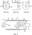
- FIGs. 3 , 4A-C , and 5-7 An exemplary embodiment of this first set of embodiments of a flow regulator valve is shown in FIGs. 3 , 4A-C , and 5-7 .
- FIG. 3 depicts a longitudinal cross section of a valve 200 which includes a cylindrical valve body 202.
- Valve body 202 is formed of a cylindrical wall 204 that encloses a control volume 210 that includes a passage way between a proximal end 206 to a distal end 208 of valve 200.
- Valve body 202 further includes proximal wall 212 and distal wall 214 at the respective ends of cylindrical valve body 202.
- Valve body 202 further includes a proximal orifice 216 in proximal wall 212 that is in fluid communication with a fluid source such as an indeflator (not shown). Valve body 202 is connected to a proximal catheter section 218 with an inflation lumen 220 that leads into proximal orifice 216.
- a fluid source such as an indeflator (not shown).
- Valve body 202 is connected to a proximal catheter section 218 with an inflation lumen 220 that leads into proximal orifice 216.
- valve body 202 has a distal orifice 222 in distal wall 214 that is in fluid communication with a delivery balloon (not shown).
- Valve body 202 is connected to a distal catheter section 224 with an inflation lumen 226 that leads into distal orifice 222.
- a cylindrical slide 228 is positioned within control volume 210 of valve body 202.
- Slide 228 has cylindrical walls 230 that enclose a passage way for flow of inflation fluid through valve body 202.
- Slide 228 further includes a distal wall 232 with two slide openings 233 which allow flow of inflation fluid distally or proximally.
- Slide 228 is positioned such that its cylindrical axis coincides with valve body 202.
- Slide 228 is slidable distally or proximally within valve body 202.
- Slide 228 has a proximal edge 229 which when abutting against inner surface of distal wall 212, prevents further proximal sliding of slide 228.
- the outer diameter of slide 228 is close to or equal to the inner diameter of valve body 202.
- the ratio of outer diameter of slide 228 and the inner diameter of valve body 202 is between 0.9 and 1 or between 0.9 and 0.99. In the configuration shown in FIG. 3 , slide 228 is in the proximal-most position.
- Valve 200 further includes a spring 234 positioned within control volume 210 between wall 232 of slide 228 and an inner surface of distal wall 214 of valve body 202.
- Spring 234 applies a proximally directed compression force that opposes the distal sliding of slide 228. In the configuration of FIG. 3 , spring 234 is in a minimum or zero force state.
- Valve 200 further includes a tubular valve seat 236 which extends proximally from distal wall 214 into control volume 210 to a valve seat edge 238.
- Valve seat 236 has a valve seat opening 240 for inflation fluid to flow to distal orifice 222.
- Valve seat 236 can be a rigid plastic or metal tube with a lumen for fluid flow.
- the valve is in its rest configuration or the configuration with a low flow rate which does not cause distal sliding of slide 228.
- a configuration may correspond to an inflation pressure between 1 and 18 atm.
- the upper limit of the inflation pressure may also be 8 atm or 24 atm.
- inflation fluid from the fluid source flows through inflation lumen 220 and proximal orifice 216, as shown by arrow 227, into control volume 210 of valve body 202.
- the inflation fluid flows through the volume enclosed by slide 228 and through slide openings 233.
- the inflation fluid then flows into valve seat 236 through valve seat opening 240 and then through distal orifice 222 into distal catheter section 224, as shown by arrow 231.
- FIGs. 4A-C depicts three cross-sectional views of cylindrical slide 228.
- FIG 4A is the view from the proximal side or left directed side from looking inside slide 228.
- FIG. 4A depicts a proximal surface of distal wall 232, distal openings 233 in distal wall 232, and proximal edge 229.
- FIG. 4B depicts the longitudinal cross-section of slide 228.
- FIG. 4C shows a distal surface of distal wall 232 of slide 228 and distal openings 233.
- slide 228 is shaped like a piston with the two openings or holes 233 therein.
- the holes are positioned symmetrically, i.e., equidistant from the center of the surface of distal wall 232 and proximal edge 229 (or inner surface of wall 230).
- the symmetric positioning of holes 233 allows the slide to move freely along the inner surface of wall 204 of valve body 202 without binding against the walls. This is due to the symmetry of the frictional forces applied to the slide by the fluid flow. Other configurations and numbers of holes are possible.
- FIG 5 depicts a configuration in which slide 228 has slid to the right and restriction to fluid flow increases.
- the restriction in the fluid flow arises due to the close proximity of section 232A of wall 232 to valve seat opening 240.
- section 232A interferes with the direct flow of fluid into valve seat opening 240. Fluid must flow around section 232A to enter valve seat opening 240.
- the gap between section 232A and valve seat edge 238 of valve seat 236 is the area available for flow into valve seat opening 240.
- valve 200 can attain a closed configuration or state such that slide 228 moves far enough to the right that proximal wall 232 engages or contacts valve seat edge 238 of valve seat 236, which is the furthest that slide 228 can slide to the right.
- FIG. 6 depicts a closed configuration of valve 200 in which slide 228 is moved to a right-most or maximal distal position.
- proximal wall 232 engages or contacts valve seat edge 238 of valve seat 236.
- the area available for fluid flow of distal opening 240 of valve seat 236 is a minimum resulting in a maximal restriction of flow since the gap between proximal wall 232 and valve seat edge 238 is at a minimum.
- Section 232A of wall 232 blocks most of the cross-sectional area of distal opening 240.
- fluid flows into two small openings where section 232A does not block distal opening 240.
- spring 234 is fully compressed.
- FIG. 7 depicts cylindrical slide 228 in the configuration of FIG. 6 viewed from the left or from a distal position. Proximal edge 238 of valve seat 236 is shown in phantom as dashed lines. As shown in FIG. 7 , openings 233 in wall 232 of slide 228 partially overlap with distal opening 240 of valve seat 236 to form two small openings 246. Therefore, even when closed all of the way, some fluid can still pass through the flow regulating valve, as shown by arrows 244.
- valve does not completely close, even at high applied pressure. This is to avoid the valve completely closing off which prevents additional inflation fluid from being administered unless the indeflator pressure is released.
- openings 246 are shown. These openings may be sized so that even if the indeflator were suddenly ramped to a high pressure such as above 12, 14, or 18 atm, the scaffold would be inflated at the desired rate. However, the physician would ideally not raise the pressure above the value targeted for the selected scaffold diameter.
- openings shown in the surface of slide 228 is exemplary and other configurations are possible.
- the surface of the slides includes openings.
- the openings are aligned with a valve seat opening such that when the surface contacts the valve seat edge, the valve seat opening is partially, but not completely blocked by a surface of the slide surface. At least a portion of the slide openings overlap the valve seat opening upon contact. The overlapping portions are an opening(s) for fluid flow when valve is completely closed.
- Another exemplary configuration for the cylindrical slide is one small opening in the center and the two holes set off to the side.
- the small hole in the center would be the high pressure bleed hole.
- This configuration would be less sensitive to alignment as the two holes set off to the side (233 for example) would not overlap at all with valve seat edge 238. With this design, should the slide shift from side to side within the valve body due to looser tolerances, the fluid flow paths through holes in wall 232 would be unaffected.
- slide 228 When the balloon is deflated, fluid flow is reversed, causing slide 228 to move completely to the left with no increase in resistance to fluid flow caused by interference of flow due to close proximity of slide 228 and valve seat 236.
- the resistance to flow due to the valve in this configuration may be the same or approximately the same as a length of catheter with no valve during balloon deflation.
- Slide 228 returns to the rest position depicted in FIG. 3 with proximal edge 229 abutting inner surface 212 of valve body 202.
- valve 200 may not be cylindrical in cross section
- the valve body and restrictor body may be conduits with other cross sectional shapes such as square or rectangular.
- the orientation of cylindrical slide could conceivably be reversed with wall 232 being situated at the proximal end of the slide.
- the valve seat 236 would need to be extended longer in the proximal direction in order to appropriately engage section 232A of wall 232.
- spring 234 would be situated inside the cylindrical slide, but would still have its distal end abutting distal wall 214.
- the position of the holes for fluid flow, 233, and the valve seat 236 would be switched.
- the valve seat would be on cylindrical slide as a tube extending from wall 232. Holes 233 would then be positioned in distal wall 214. This configuration has the challenge that the region of greatest pressure drop is not necessarily associated with the cylindrical slide, and this may alter the valve sensitivity.
- Valve 200 may be present in the catheter during the manufacturing process of the scaffold-balloon-catheter assembly. For example, if the balloon is pressurized with air during crimping, the valve would not activate as the low viscosity of air will not move the slide. Similarly, the catheter may be leak tested with the valve in place as air will not activate the valve.
- valve body diameter the valve body diameter
- valve body length the valve body length
- slide diameter the slide diameter
- slide length the valve length
- spring constant the valve opening(s) size
- slide opening(s) position(s) the slide opening(s) position(s)
- slide opening(s) spacing the valve body diameter, valve body length, slide diameter, slide length, spring constant.
- the basic shape can be input into a computational fluid mechanics software.
- Inflation media has a viscosity in the range of 2-4 cP and can be modeled as a Newtonian fluid. Modeling the valve behavior on the computer allows an approximate design to be established. Then, prototype valves could be machined with bodies of a metal such as aluminum, slides of metal or rigid plastic such as Delrin (polyoxymethylene) made by DuPont, and springs of a metal such as 300 series stainless steel. Once the design is finalized, the valve body and cylindrical slide may be injection molded or machined. Assembly of the final valve may be done with solvent welding, adhesive gluing, or ultrasonic welding.
- Different balloon sizes require a different volumetric flow rate to achieve the desired scaffold inflation rate.
- different target volumetric flow rates could be achieved. Adjustment of these slide parameters to achieve the desired fluid flow rate for each balloon size allows the use of different cylindrical slides with the same valve body and spring. For example, a large balloon will allow a larger volumetric flow rate to achieve the target scaffold inflation rate. This might be achieved by simply making the though holes in the cylindrical slide larger.
- valves of the flow regulators according to the invention can be designed such that the restriction of flow does not start until the pressure exceeds a specified maximum pressure. Prior to reaching this specified maximum pressure, the pressurization rate can be higher than the maximum specified pressurization rate.
- the maximum specified pressure may be about 2atm, about 3 atm, about 4 atm, 2 to 4 atm, 2 to 3 atm, or 3 to 4 atm.
- the pressurization rate can be up to 27.6, 41.4, 68.9, 137.9 kPa/sec (4, 6, 10, 20 psi/sec), about 206.8 kPa/sec (30 psi/sec), 68.9 to 137.9 kPa/sec (10 to 20 psi/sec), or 137.9 to 206.8 kPa/sec (20 to 30 psi/sec).
- the pressurization rate below the maximum specified pressure may be entirely under the control of the operator of the inflation device.
- the average pressurization rate between the maximum specified pressure and the maximum deployment pressure may be controlled to be about 27.6, 34.5, 41.4, 48.3, 55.2, 68.9 kPa/sec (4, 5, 6, 7, 8, 10 psi/sec), 41.4 to 55.2 kPa/sec (6 to 8 psi/ sec), 41.4 to 68.9 kPa/sec (6 to 10 psi/sec), 55.2 to 68.9 kPa/sec (8 to 10 psi/sec).
- the instantaneous pressurization rate may also be controlled to within these ranges.
- the maximum deployment pressure can depend on the desired diameter of deployment.
- the maximum pressure may be about 7 atm, about 8 atm, about 10 atm, about 12 atm, about 14 atm, about 16 atm, about 18 atm, 7 to 8 atm, 8 to 10 atm, or 10 to 24 atm.
Landscapes
- Health & Medical Sciences (AREA)
- Heart & Thoracic Surgery (AREA)
- Life Sciences & Earth Sciences (AREA)
- Engineering & Computer Science (AREA)
- Biomedical Technology (AREA)
- Animal Behavior & Ethology (AREA)
- Veterinary Medicine (AREA)
- Public Health (AREA)
- General Health & Medical Sciences (AREA)
- Hematology (AREA)
- Pulmonology (AREA)
- Anesthesiology (AREA)
- Child & Adolescent Psychology (AREA)
- Biophysics (AREA)
- Vascular Medicine (AREA)
- Transplantation (AREA)
- Oral & Maxillofacial Surgery (AREA)
- Cardiology (AREA)
- Media Introduction/Drainage Providing Device (AREA)
- Safety Valves (AREA)
Applications Claiming Priority (2)
| Application Number | Priority Date | Filing Date | Title |
|---|---|---|---|
| US13/471,263 US9289319B2 (en) | 2012-05-14 | 2012-05-14 | Flow regulation valve for controlling inflation rate of a balloon deploying a scaffold |
| PCT/US2013/039980 WO2013173127A1 (en) | 2012-05-14 | 2013-05-07 | Flow regulation valve for controlling inflation rate of a balloon deploying a scaffold |
Publications (2)
| Publication Number | Publication Date |
|---|---|
| EP2849691A1 EP2849691A1 (en) | 2015-03-25 |
| EP2849691B1 true EP2849691B1 (en) | 2018-12-05 |
Family
ID=48464128
Family Applications (1)
| Application Number | Title | Priority Date | Filing Date |
|---|---|---|---|
| EP13723645.1A Not-in-force EP2849691B1 (en) | 2012-05-14 | 2013-05-07 | Flow regulation valve for controlling inflation rate of a balloon deploying a scaffold |
Country Status (5)
| Country | Link |
|---|---|
| US (2) | US9289319B2 (enExample) |
| EP (1) | EP2849691B1 (enExample) |
| JP (1) | JP6220867B2 (enExample) |
| HK (1) | HK1208615A1 (enExample) |
| WO (1) | WO2013173127A1 (enExample) |
Families Citing this family (18)
| Publication number | Priority date | Publication date | Assignee | Title |
|---|---|---|---|---|
| US10231770B2 (en) | 2015-01-09 | 2019-03-19 | Medtronic Holding Company Sárl | Tumor ablation system |
| CN110944689B (zh) | 2017-06-07 | 2022-12-09 | 施菲姆德控股有限责任公司 | 血管内流体运动设备、系统和使用方法 |
| EP3710076B1 (en) | 2017-11-13 | 2023-12-27 | Shifamed Holdings, LLC | Intravascular fluid movement devices, systems, and methods of use |
| WO2019152875A1 (en) | 2018-02-01 | 2019-08-08 | Shifamed Holdings, Llc | Intravascular blood pumps and methods of use and manufacture |
| CN108744152B (zh) * | 2018-07-09 | 2020-10-23 | 程其明 | 输液器 |
| WO2020028537A1 (en) | 2018-07-31 | 2020-02-06 | Shifamed Holdings, Llc | Intravascaular blood pumps and methods of use |
| US12220570B2 (en) | 2018-10-05 | 2025-02-11 | Shifamed Holdings, Llc | Intravascular blood pumps and methods of use |
| EP3996797A4 (en) | 2019-07-12 | 2023-08-02 | Shifamed Holdings, LLC | INTRAVASCULAR BLOOD PUMPS AND METHOD OF USE AND METHOD OF MAKING |
| US11654275B2 (en) | 2019-07-22 | 2023-05-23 | Shifamed Holdings, Llc | Intravascular blood pumps with struts and methods of use and manufacture |
| EP4010046A4 (en) | 2019-08-07 | 2023-08-30 | Calomeni, Michael | Catheter blood pumps and collapsible pump housings |
| WO2021062260A1 (en) | 2019-09-25 | 2021-04-01 | Shifamed Holdings, Llc | Catheter blood pumps and collapsible blood conduits |
| WO2021062270A1 (en) | 2019-09-25 | 2021-04-01 | Shifamed Holdings, Llc | Catheter blood pumps and collapsible pump housings |
| WO2021062265A1 (en) | 2019-09-25 | 2021-04-01 | Shifamed Holdings, Llc | Intravascular blood pump systems and methods of use and control thereof |
| WO2021119478A1 (en) | 2019-12-11 | 2021-06-17 | Shifamed Holdings, Llc | Descending aorta and vena cava blood pumps |
| EP4065042A4 (en) * | 2020-01-10 | 2023-01-11 | Meril Life Sciences Pvt Ltd | STENT SYSTEM FOR TREATMENT OF DIFFUSED LESIONS IN FORCATED ARTERIES |
| US12446961B2 (en) | 2020-02-10 | 2025-10-21 | Bolt Medical, Inc. | System and method for pressure monitoring within a catheter system |
| US11484355B2 (en) | 2020-03-02 | 2022-11-01 | Medtronic Holding Company Sàrl | Inflatable bone tamp and method for use of inflatable bone tamp |
| JP7145549B1 (ja) | 2022-04-26 | 2022-10-03 | トーフレ株式会社 | 流量調整ユニット及び流量調整ユニットを組み入れたファインバブル発生機能付き給水装置 |
Citations (1)
| Publication number | Priority date | Publication date | Assignee | Title |
|---|---|---|---|---|
| US6050973A (en) * | 1998-09-14 | 2000-04-18 | Ave Connaught | Pressure limiting device |
Family Cites Families (17)
| Publication number | Priority date | Publication date | Assignee | Title |
|---|---|---|---|---|
| US3795246A (en) * | 1973-01-26 | 1974-03-05 | Bard Inc C R | Venocclusion device |
| US4429856A (en) * | 1981-12-18 | 1984-02-07 | Mallinckrodt, Inc. | Inflation valve |
| US4957483A (en) * | 1988-10-21 | 1990-09-18 | Den-Tal-Ez, Inc. | Sterilizable syringe |
| US5514110A (en) * | 1993-03-22 | 1996-05-07 | Teh; Eutiquio L. | Automatic flow control device |
| US5437632A (en) * | 1993-06-02 | 1995-08-01 | Target Therapeutics, Inc. | Variable stiffness balloon catheter |
| US6458096B1 (en) | 1996-04-01 | 2002-10-01 | Medtronic, Inc. | Catheter with autoinflating, autoregulating balloon |
| US5893868A (en) | 1997-03-05 | 1999-04-13 | Scimed Life Systems, Inc. | Catheter with removable balloon protector and stent delivery system with removable stent protector |
| US6419657B1 (en) * | 2000-08-22 | 2002-07-16 | Advanced Cardiovascular Systems, Inc. | Flow regulator valve to optimize stent deployment and method of using the same |
| US20030078538A1 (en) | 2000-12-28 | 2003-04-24 | Neale Paul V. | Inflation device for dual balloon catheter |
| US7971333B2 (en) | 2006-05-30 | 2011-07-05 | Advanced Cardiovascular Systems, Inc. | Manufacturing process for polymetric stents |
| US7921874B2 (en) * | 2004-11-12 | 2011-04-12 | Cook Medical Technologies Llc | Flow variation valve assembly |
| US8388673B2 (en) | 2008-05-02 | 2013-03-05 | Abbott Cardiovascular Systems Inc. | Polymeric stent |
| US8002817B2 (en) | 2007-05-04 | 2011-08-23 | Abbott Cardiovascular Systems Inc. | Stents with high radial strength and methods of manufacturing same |
| US8162902B2 (en) | 2008-04-04 | 2012-04-24 | Becton, Dickinson And Company | Systems and methods for providing an automatic occlusion device |
| ES2378012B1 (es) | 2009-01-29 | 2013-02-12 | Innova Salud Desarrollos Sanitarios S.L. | Dispositivo para la administración de productos inyectables con caudal controlado. |
| US9168361B2 (en) * | 2010-04-30 | 2015-10-27 | Abbott Cardiovascular Systems Inc. | Balloon catheter exhibiting rapid inflation and deflation |
| EP2563446A1 (en) | 2010-04-30 | 2013-03-06 | Abbott Cardiovascular Systems Inc. | Improved balloon catheter exhibiting rapid inflation and deflation |
-
2012
- 2012-05-14 US US13/471,263 patent/US9289319B2/en not_active Expired - Fee Related
-
2013
- 2013-05-07 HK HK15109309.0A patent/HK1208615A1/xx unknown
- 2013-05-07 JP JP2015512687A patent/JP6220867B2/ja not_active Expired - Fee Related
- 2013-05-07 EP EP13723645.1A patent/EP2849691B1/en not_active Not-in-force
- 2013-05-07 WO PCT/US2013/039980 patent/WO2013173127A1/en not_active Ceased
-
2016
- 2016-02-04 US US15/015,945 patent/US10441448B2/en not_active Expired - Fee Related
Patent Citations (1)
| Publication number | Priority date | Publication date | Assignee | Title |
|---|---|---|---|---|
| US6050973A (en) * | 1998-09-14 | 2000-04-18 | Ave Connaught | Pressure limiting device |
Also Published As
| Publication number | Publication date |
|---|---|
| JP6220867B2 (ja) | 2017-10-25 |
| US20130304182A1 (en) | 2013-11-14 |
| HK1208615A1 (en) | 2016-03-11 |
| EP2849691A1 (en) | 2015-03-25 |
| WO2013173127A1 (en) | 2013-11-21 |
| US20160158046A1 (en) | 2016-06-09 |
| US9289319B2 (en) | 2016-03-22 |
| JP2015519947A (ja) | 2015-07-16 |
| US10441448B2 (en) | 2019-10-15 |
Similar Documents
| Publication | Publication Date | Title |
|---|---|---|
| EP2849691B1 (en) | Flow regulation valve for controlling inflation rate of a balloon deploying a scaffold | |
| US9517151B2 (en) | Control of balloon inflation rate during deployment of scaffold | |
| JP6032821B2 (ja) | 圧潰復元可能なポリマースキャフォールドの作製方法 | |
| CA1281504C (en) | Expandable intraluminal graft, and apparatus for implanting an expandable intraluminal graft | |
| JP2933226B2 (ja) | 伸張可能な管腔内脈管移植片及び身体通路の管腔を伸張させる装置 | |
| US5195984A (en) | Expandable intraluminal graft | |
| EP1755485B1 (en) | Method and system for stent retention using an adhesive | |
| CN112399832A (zh) | 在扩张时缩短从而为血管运动产生空间的可吸收血管内装置 | |
| JP2009500121A (ja) | 管腔内の動脈瘤治療のためのシステム及び方法 | |
| US20180360626A1 (en) | Shape change structure for treatment of nasal conditions including sinusitis | |
| JP2012500673A (ja) | 方向性のある拡張をする脈管内器具 | |
| JPH1119219A (ja) | ステント | |
| CN107835676B (zh) | 气囊导管 | |
| CN104906682A (zh) | 铰接气囊导管及其使用方法 | |
| JP2008509784A (ja) | 血管遮断装置 | |
| WO2016057402A1 (en) | Stent with elongating struts | |
| EP1836998B1 (en) | Split sheath delivery system for self expanding stents | |
| HK1206584B (en) | Control of balloon inflation rate during deployment of scaffold | |
| CN119421676A (zh) | 可变直径支架 |
Legal Events
| Date | Code | Title | Description |
|---|---|---|---|
| PUAI | Public reference made under article 153(3) epc to a published international application that has entered the european phase |
Free format text: ORIGINAL CODE: 0009012 |
|
| 17P | Request for examination filed |
Effective date: 20141215 |
|
| AK | Designated contracting states |
Kind code of ref document: A1 Designated state(s): AL AT BE BG CH CY CZ DE DK EE ES FI FR GB GR HR HU IE IS IT LI LT LU LV MC MK MT NL NO PL PT RO RS SE SI SK SM TR |
|
| AX | Request for extension of the european patent |
Extension state: BA ME |
|
| RAP1 | Party data changed (applicant data changed or rights of an application transferred) |
Owner name: ABBOTT CARDIOVASCULAR SYSTEMS INC. |
|
| DAX | Request for extension of the european patent (deleted) | ||
| REG | Reference to a national code |
Ref country code: HK Ref legal event code: DE Ref document number: 1208615 Country of ref document: HK |
|
| 17Q | First examination report despatched |
Effective date: 20160818 |
|
| STAA | Information on the status of an ep patent application or granted ep patent |
Free format text: STATUS: EXAMINATION IS IN PROGRESS |
|
| GRAP | Despatch of communication of intention to grant a patent |
Free format text: ORIGINAL CODE: EPIDOSNIGR1 |
|
| STAA | Information on the status of an ep patent application or granted ep patent |
Free format text: STATUS: GRANT OF PATENT IS INTENDED |
|
| INTG | Intention to grant announced |
Effective date: 20180704 |
|
| GRAS | Grant fee paid |
Free format text: ORIGINAL CODE: EPIDOSNIGR3 |
|
| GRAA | (expected) grant |
Free format text: ORIGINAL CODE: 0009210 |
|
| STAA | Information on the status of an ep patent application or granted ep patent |
Free format text: STATUS: THE PATENT HAS BEEN GRANTED |
|
| AK | Designated contracting states |
Kind code of ref document: B1 Designated state(s): AL AT BE BG CH CY CZ DE DK EE ES FI FR GB GR HR HU IE IS IT LI LT LU LV MC MK MT NL NO PL PT RO RS SE SI SK SM TR |
|
| REG | Reference to a national code |
Ref country code: GB Ref legal event code: FG4D |
|
| REG | Reference to a national code |
Ref country code: CH Ref legal event code: EP |
|
| REG | Reference to a national code |
Ref country code: AT Ref legal event code: REF Ref document number: 1072136 Country of ref document: AT Kind code of ref document: T Effective date: 20181215 |
|
| REG | Reference to a national code |
Ref country code: IE Ref legal event code: FG4D |
|
| REG | Reference to a national code |
Ref country code: DE Ref legal event code: R096 Ref document number: 602013047758 Country of ref document: DE |
|
| REG | Reference to a national code |
Ref country code: NL Ref legal event code: FP |
|
| REG | Reference to a national code |
Ref country code: AT Ref legal event code: MK05 Ref document number: 1072136 Country of ref document: AT Kind code of ref document: T Effective date: 20181205 |
|
| REG | Reference to a national code |
Ref country code: LT Ref legal event code: MG4D |
|
| PG25 | Lapsed in a contracting state [announced via postgrant information from national office to epo] |
Ref country code: ES Free format text: LAPSE BECAUSE OF FAILURE TO SUBMIT A TRANSLATION OF THE DESCRIPTION OR TO PAY THE FEE WITHIN THE PRESCRIBED TIME-LIMIT Effective date: 20181205 Ref country code: AT Free format text: LAPSE BECAUSE OF FAILURE TO SUBMIT A TRANSLATION OF THE DESCRIPTION OR TO PAY THE FEE WITHIN THE PRESCRIBED TIME-LIMIT Effective date: 20181205 Ref country code: HR Free format text: LAPSE BECAUSE OF FAILURE TO SUBMIT A TRANSLATION OF THE DESCRIPTION OR TO PAY THE FEE WITHIN THE PRESCRIBED TIME-LIMIT Effective date: 20181205 Ref country code: NO Free format text: LAPSE BECAUSE OF FAILURE TO SUBMIT A TRANSLATION OF THE DESCRIPTION OR TO PAY THE FEE WITHIN THE PRESCRIBED TIME-LIMIT Effective date: 20190305 Ref country code: BG Free format text: LAPSE BECAUSE OF FAILURE TO SUBMIT A TRANSLATION OF THE DESCRIPTION OR TO PAY THE FEE WITHIN THE PRESCRIBED TIME-LIMIT Effective date: 20190305 Ref country code: LT Free format text: LAPSE BECAUSE OF FAILURE TO SUBMIT A TRANSLATION OF THE DESCRIPTION OR TO PAY THE FEE WITHIN THE PRESCRIBED TIME-LIMIT Effective date: 20181205 Ref country code: FI Free format text: LAPSE BECAUSE OF FAILURE TO SUBMIT A TRANSLATION OF THE DESCRIPTION OR TO PAY THE FEE WITHIN THE PRESCRIBED TIME-LIMIT Effective date: 20181205 Ref country code: LV Free format text: LAPSE BECAUSE OF FAILURE TO SUBMIT A TRANSLATION OF THE DESCRIPTION OR TO PAY THE FEE WITHIN THE PRESCRIBED TIME-LIMIT Effective date: 20181205 |
|
| PG25 | Lapsed in a contracting state [announced via postgrant information from national office to epo] |
Ref country code: AL Free format text: LAPSE BECAUSE OF FAILURE TO SUBMIT A TRANSLATION OF THE DESCRIPTION OR TO PAY THE FEE WITHIN THE PRESCRIBED TIME-LIMIT Effective date: 20181205 Ref country code: SE Free format text: LAPSE BECAUSE OF FAILURE TO SUBMIT A TRANSLATION OF THE DESCRIPTION OR TO PAY THE FEE WITHIN THE PRESCRIBED TIME-LIMIT Effective date: 20181205 Ref country code: RS Free format text: LAPSE BECAUSE OF FAILURE TO SUBMIT A TRANSLATION OF THE DESCRIPTION OR TO PAY THE FEE WITHIN THE PRESCRIBED TIME-LIMIT Effective date: 20181205 Ref country code: GR Free format text: LAPSE BECAUSE OF FAILURE TO SUBMIT A TRANSLATION OF THE DESCRIPTION OR TO PAY THE FEE WITHIN THE PRESCRIBED TIME-LIMIT Effective date: 20190306 |
|
| PG25 | Lapsed in a contracting state [announced via postgrant information from national office to epo] |
Ref country code: PT Free format text: LAPSE BECAUSE OF FAILURE TO SUBMIT A TRANSLATION OF THE DESCRIPTION OR TO PAY THE FEE WITHIN THE PRESCRIBED TIME-LIMIT Effective date: 20190405 Ref country code: CZ Free format text: LAPSE BECAUSE OF FAILURE TO SUBMIT A TRANSLATION OF THE DESCRIPTION OR TO PAY THE FEE WITHIN THE PRESCRIBED TIME-LIMIT Effective date: 20181205 Ref country code: PL Free format text: LAPSE BECAUSE OF FAILURE TO SUBMIT A TRANSLATION OF THE DESCRIPTION OR TO PAY THE FEE WITHIN THE PRESCRIBED TIME-LIMIT Effective date: 20181205 Ref country code: IT Free format text: LAPSE BECAUSE OF FAILURE TO SUBMIT A TRANSLATION OF THE DESCRIPTION OR TO PAY THE FEE WITHIN THE PRESCRIBED TIME-LIMIT Effective date: 20181205 |
|
| PG25 | Lapsed in a contracting state [announced via postgrant information from national office to epo] |
Ref country code: EE Free format text: LAPSE BECAUSE OF FAILURE TO SUBMIT A TRANSLATION OF THE DESCRIPTION OR TO PAY THE FEE WITHIN THE PRESCRIBED TIME-LIMIT Effective date: 20181205 Ref country code: SM Free format text: LAPSE BECAUSE OF FAILURE TO SUBMIT A TRANSLATION OF THE DESCRIPTION OR TO PAY THE FEE WITHIN THE PRESCRIBED TIME-LIMIT Effective date: 20181205 Ref country code: RO Free format text: LAPSE BECAUSE OF FAILURE TO SUBMIT A TRANSLATION OF THE DESCRIPTION OR TO PAY THE FEE WITHIN THE PRESCRIBED TIME-LIMIT Effective date: 20181205 Ref country code: IS Free format text: LAPSE BECAUSE OF FAILURE TO SUBMIT A TRANSLATION OF THE DESCRIPTION OR TO PAY THE FEE WITHIN THE PRESCRIBED TIME-LIMIT Effective date: 20190405 Ref country code: SK Free format text: LAPSE BECAUSE OF FAILURE TO SUBMIT A TRANSLATION OF THE DESCRIPTION OR TO PAY THE FEE WITHIN THE PRESCRIBED TIME-LIMIT Effective date: 20181205 |
|
| REG | Reference to a national code |
Ref country code: DE Ref legal event code: R097 Ref document number: 602013047758 Country of ref document: DE |
|
| PLBE | No opposition filed within time limit |
Free format text: ORIGINAL CODE: 0009261 |
|
| STAA | Information on the status of an ep patent application or granted ep patent |
Free format text: STATUS: NO OPPOSITION FILED WITHIN TIME LIMIT |
|
| PG25 | Lapsed in a contracting state [announced via postgrant information from national office to epo] |
Ref country code: DK Free format text: LAPSE BECAUSE OF FAILURE TO SUBMIT A TRANSLATION OF THE DESCRIPTION OR TO PAY THE FEE WITHIN THE PRESCRIBED TIME-LIMIT Effective date: 20181205 Ref country code: SI Free format text: LAPSE BECAUSE OF FAILURE TO SUBMIT A TRANSLATION OF THE DESCRIPTION OR TO PAY THE FEE WITHIN THE PRESCRIBED TIME-LIMIT Effective date: 20181205 |
|
| 26N | No opposition filed |
Effective date: 20190906 |
|
| REG | Reference to a national code |
Ref country code: CH Ref legal event code: PL |
|
| PG25 | Lapsed in a contracting state [announced via postgrant information from national office to epo] |
Ref country code: CH Free format text: LAPSE BECAUSE OF NON-PAYMENT OF DUE FEES Effective date: 20190531 Ref country code: LI Free format text: LAPSE BECAUSE OF NON-PAYMENT OF DUE FEES Effective date: 20190531 Ref country code: MC Free format text: LAPSE BECAUSE OF FAILURE TO SUBMIT A TRANSLATION OF THE DESCRIPTION OR TO PAY THE FEE WITHIN THE PRESCRIBED TIME-LIMIT Effective date: 20181205 |
|
| REG | Reference to a national code |
Ref country code: BE Ref legal event code: MM Effective date: 20190531 |
|
| PG25 | Lapsed in a contracting state [announced via postgrant information from national office to epo] |
Ref country code: LU Free format text: LAPSE BECAUSE OF NON-PAYMENT OF DUE FEES Effective date: 20190507 |
|
| PG25 | Lapsed in a contracting state [announced via postgrant information from national office to epo] |
Ref country code: TR Free format text: LAPSE BECAUSE OF FAILURE TO SUBMIT A TRANSLATION OF THE DESCRIPTION OR TO PAY THE FEE WITHIN THE PRESCRIBED TIME-LIMIT Effective date: 20181205 |
|
| PG25 | Lapsed in a contracting state [announced via postgrant information from national office to epo] |
Ref country code: BE Free format text: LAPSE BECAUSE OF NON-PAYMENT OF DUE FEES Effective date: 20190531 |
|
| PG25 | Lapsed in a contracting state [announced via postgrant information from national office to epo] |
Ref country code: FR Free format text: LAPSE BECAUSE OF NON-PAYMENT OF DUE FEES Effective date: 20190531 |
|
| PGFP | Annual fee paid to national office [announced via postgrant information from national office to epo] |
Ref country code: IE Payment date: 20200429 Year of fee payment: 8 Ref country code: DE Payment date: 20200417 Year of fee payment: 8 Ref country code: NL Payment date: 20200421 Year of fee payment: 8 |
|
| PGFP | Annual fee paid to national office [announced via postgrant information from national office to epo] |
Ref country code: GB Payment date: 20200429 Year of fee payment: 8 |
|
| PG25 | Lapsed in a contracting state [announced via postgrant information from national office to epo] |
Ref country code: CY Free format text: LAPSE BECAUSE OF FAILURE TO SUBMIT A TRANSLATION OF THE DESCRIPTION OR TO PAY THE FEE WITHIN THE PRESCRIBED TIME-LIMIT Effective date: 20181205 |
|
| PG25 | Lapsed in a contracting state [announced via postgrant information from national office to epo] |
Ref country code: MT Free format text: LAPSE BECAUSE OF FAILURE TO SUBMIT A TRANSLATION OF THE DESCRIPTION OR TO PAY THE FEE WITHIN THE PRESCRIBED TIME-LIMIT Effective date: 20181205 Ref country code: HU Free format text: LAPSE BECAUSE OF FAILURE TO SUBMIT A TRANSLATION OF THE DESCRIPTION OR TO PAY THE FEE WITHIN THE PRESCRIBED TIME-LIMIT; INVALID AB INITIO Effective date: 20130507 |
|
| REG | Reference to a national code |
Ref country code: DE Ref legal event code: R119 Ref document number: 602013047758 Country of ref document: DE |
|
| REG | Reference to a national code |
Ref country code: HK Ref legal event code: WD Ref document number: 1208615 Country of ref document: HK |
|
| REG | Reference to a national code |
Ref country code: NL Ref legal event code: MM Effective date: 20210601 |
|
| GBPC | Gb: european patent ceased through non-payment of renewal fee |
Effective date: 20210507 |
|
| PG25 | Lapsed in a contracting state [announced via postgrant information from national office to epo] |
Ref country code: IE Free format text: LAPSE BECAUSE OF NON-PAYMENT OF DUE FEES Effective date: 20210507 Ref country code: GB Free format text: LAPSE BECAUSE OF NON-PAYMENT OF DUE FEES Effective date: 20210507 Ref country code: DE Free format text: LAPSE BECAUSE OF NON-PAYMENT OF DUE FEES Effective date: 20211201 |
|
| PG25 | Lapsed in a contracting state [announced via postgrant information from national office to epo] |
Ref country code: NL Free format text: LAPSE BECAUSE OF NON-PAYMENT OF DUE FEES Effective date: 20210601 |
|
| PG25 | Lapsed in a contracting state [announced via postgrant information from national office to epo] |
Ref country code: MK Free format text: LAPSE BECAUSE OF FAILURE TO SUBMIT A TRANSLATION OF THE DESCRIPTION OR TO PAY THE FEE WITHIN THE PRESCRIBED TIME-LIMIT Effective date: 20181205 |