EP2849262A1 - Elément de batterie présentant une structure amorphe et module de batterie le comprenant - Google Patents
Elément de batterie présentant une structure amorphe et module de batterie le comprenant Download PDFInfo
- Publication number
- EP2849262A1 EP2849262A1 EP13787997.9A EP13787997A EP2849262A1 EP 2849262 A1 EP2849262 A1 EP 2849262A1 EP 13787997 A EP13787997 A EP 13787997A EP 2849262 A1 EP2849262 A1 EP 2849262A1
- Authority
- EP
- European Patent Office
- Prior art keywords
- battery
- battery cell
- cell according
- electrode terminals
- viewed
- Prior art date
- Legal status (The legal status is an assumption and is not a legal conclusion. Google has not performed a legal analysis and makes no representation as to the accuracy of the status listed.)
- Granted
Links
- 230000000994 depressogenic effect Effects 0.000 claims abstract description 32
- HBBGRARXTFLTSG-UHFFFAOYSA-N Lithium ion Chemical compound [Li+] HBBGRARXTFLTSG-UHFFFAOYSA-N 0.000 claims description 6
- 229910001416 lithium ion Inorganic materials 0.000 claims description 6
- 229910052751 metal Inorganic materials 0.000 claims description 6
- 239000002184 metal Substances 0.000 claims description 6
- 239000011347 resin Substances 0.000 claims description 6
- 229920005989 resin Polymers 0.000 claims description 6
- 229920000642 polymer Polymers 0.000 claims description 4
- 229910052782 aluminium Inorganic materials 0.000 claims description 3
- XAGFODPZIPBFFR-UHFFFAOYSA-N aluminium Chemical compound [Al] XAGFODPZIPBFFR-UHFFFAOYSA-N 0.000 claims description 3
- 239000000463 material Substances 0.000 claims description 3
- 238000003860 storage Methods 0.000 claims description 2
- 238000004519 manufacturing process Methods 0.000 description 10
- 238000000429 assembly Methods 0.000 description 8
- 230000000712 assembly Effects 0.000 description 8
- 230000010354 integration Effects 0.000 description 6
- WHXSMMKQMYFTQS-UHFFFAOYSA-N Lithium Chemical compound [Li] WHXSMMKQMYFTQS-UHFFFAOYSA-N 0.000 description 4
- 229910052744 lithium Inorganic materials 0.000 description 4
- 238000010276 construction Methods 0.000 description 3
- 238000003466 welding Methods 0.000 description 3
- 239000003792 electrolyte Substances 0.000 description 2
- 238000012986 modification Methods 0.000 description 2
- 230000004048 modification Effects 0.000 description 2
- 238000007789 sealing Methods 0.000 description 2
- 238000007792 addition Methods 0.000 description 1
- 230000001747 exhibiting effect Effects 0.000 description 1
- 238000002474 experimental method Methods 0.000 description 1
- 238000009434 installation Methods 0.000 description 1
- 230000001788 irregular Effects 0.000 description 1
- 238000002955 isolation Methods 0.000 description 1
- 230000014759 maintenance of location Effects 0.000 description 1
- 230000035515 penetration Effects 0.000 description 1
- 238000006467 substitution reaction Methods 0.000 description 1
Images


Classifications
-
- H—ELECTRICITY
- H01—ELECTRIC ELEMENTS
- H01M—PROCESSES OR MEANS, e.g. BATTERIES, FOR THE DIRECT CONVERSION OF CHEMICAL ENERGY INTO ELECTRICAL ENERGY
- H01M50/00—Constructional details or processes of manufacture of the non-active parts of electrochemical cells other than fuel cells, e.g. hybrid cells
- H01M50/10—Primary casings, jackets or wrappings of a single cell or a single battery
- H01M50/116—Primary casings, jackets or wrappings of a single cell or a single battery characterised by the material
- H01M50/124—Primary casings, jackets or wrappings of a single cell or a single battery characterised by the material having a layered structure
-
- H—ELECTRICITY
- H01—ELECTRIC ELEMENTS
- H01M—PROCESSES OR MEANS, e.g. BATTERIES, FOR THE DIRECT CONVERSION OF CHEMICAL ENERGY INTO ELECTRICAL ENERGY
- H01M50/00—Constructional details or processes of manufacture of the non-active parts of electrochemical cells other than fuel cells, e.g. hybrid cells
- H01M50/50—Current conducting connections for cells or batteries
- H01M50/531—Electrode connections inside a battery casing
-
- H—ELECTRICITY
- H01—ELECTRIC ELEMENTS
- H01M—PROCESSES OR MEANS, e.g. BATTERIES, FOR THE DIRECT CONVERSION OF CHEMICAL ENERGY INTO ELECTRICAL ENERGY
- H01M10/00—Secondary cells; Manufacture thereof
- H01M10/05—Accumulators with non-aqueous electrolyte
- H01M10/052—Li-accumulators
-
- H—ELECTRICITY
- H01—ELECTRIC ELEMENTS
- H01M—PROCESSES OR MEANS, e.g. BATTERIES, FOR THE DIRECT CONVERSION OF CHEMICAL ENERGY INTO ELECTRICAL ENERGY
- H01M10/00—Secondary cells; Manufacture thereof
- H01M10/05—Accumulators with non-aqueous electrolyte
- H01M10/052—Li-accumulators
- H01M10/0525—Rocking-chair batteries, i.e. batteries with lithium insertion or intercalation in both electrodes; Lithium-ion batteries
-
- H—ELECTRICITY
- H01—ELECTRIC ELEMENTS
- H01M—PROCESSES OR MEANS, e.g. BATTERIES, FOR THE DIRECT CONVERSION OF CHEMICAL ENERGY INTO ELECTRICAL ENERGY
- H01M50/00—Constructional details or processes of manufacture of the non-active parts of electrochemical cells other than fuel cells, e.g. hybrid cells
- H01M50/10—Primary casings, jackets or wrappings of a single cell or a single battery
- H01M50/102—Primary casings, jackets or wrappings of a single cell or a single battery characterised by their shape or physical structure
- H01M50/103—Primary casings, jackets or wrappings of a single cell or a single battery characterised by their shape or physical structure prismatic or rectangular
-
- H—ELECTRICITY
- H01—ELECTRIC ELEMENTS
- H01M—PROCESSES OR MEANS, e.g. BATTERIES, FOR THE DIRECT CONVERSION OF CHEMICAL ENERGY INTO ELECTRICAL ENERGY
- H01M50/00—Constructional details or processes of manufacture of the non-active parts of electrochemical cells other than fuel cells, e.g. hybrid cells
- H01M50/10—Primary casings, jackets or wrappings of a single cell or a single battery
- H01M50/102—Primary casings, jackets or wrappings of a single cell or a single battery characterised by their shape or physical structure
- H01M50/105—Pouches or flexible bags
-
- H—ELECTRICITY
- H01—ELECTRIC ELEMENTS
- H01M—PROCESSES OR MEANS, e.g. BATTERIES, FOR THE DIRECT CONVERSION OF CHEMICAL ENERGY INTO ELECTRICAL ENERGY
- H01M50/00—Constructional details or processes of manufacture of the non-active parts of electrochemical cells other than fuel cells, e.g. hybrid cells
- H01M50/10—Primary casings, jackets or wrappings of a single cell or a single battery
- H01M50/116—Primary casings, jackets or wrappings of a single cell or a single battery characterised by the material
- H01M50/117—Inorganic material
- H01M50/119—Metals
-
- H—ELECTRICITY
- H01—ELECTRIC ELEMENTS
- H01M—PROCESSES OR MEANS, e.g. BATTERIES, FOR THE DIRECT CONVERSION OF CHEMICAL ENERGY INTO ELECTRICAL ENERGY
- H01M50/00—Constructional details or processes of manufacture of the non-active parts of electrochemical cells other than fuel cells, e.g. hybrid cells
- H01M50/10—Primary casings, jackets or wrappings of a single cell or a single battery
- H01M50/116—Primary casings, jackets or wrappings of a single cell or a single battery characterised by the material
- H01M50/121—Organic material
-
- H—ELECTRICITY
- H01—ELECTRIC ELEMENTS
- H01M—PROCESSES OR MEANS, e.g. BATTERIES, FOR THE DIRECT CONVERSION OF CHEMICAL ENERGY INTO ELECTRICAL ENERGY
- H01M50/00—Constructional details or processes of manufacture of the non-active parts of electrochemical cells other than fuel cells, e.g. hybrid cells
- H01M50/10—Primary casings, jackets or wrappings of a single cell or a single battery
- H01M50/172—Arrangements of electric connectors penetrating the casing
- H01M50/174—Arrangements of electric connectors penetrating the casing adapted for the shape of the cells
- H01M50/178—Arrangements of electric connectors penetrating the casing adapted for the shape of the cells for pouch or flexible bag cells
-
- H—ELECTRICITY
- H01—ELECTRIC ELEMENTS
- H01M—PROCESSES OR MEANS, e.g. BATTERIES, FOR THE DIRECT CONVERSION OF CHEMICAL ENERGY INTO ELECTRICAL ENERGY
- H01M50/00—Constructional details or processes of manufacture of the non-active parts of electrochemical cells other than fuel cells, e.g. hybrid cells
- H01M50/20—Mountings; Secondary casings or frames; Racks, modules or packs; Suspension devices; Shock absorbers; Transport or carrying devices; Holders
- H01M50/204—Racks, modules or packs for multiple batteries or multiple cells
- H01M50/207—Racks, modules or packs for multiple batteries or multiple cells characterised by their shape
- H01M50/211—Racks, modules or packs for multiple batteries or multiple cells characterised by their shape adapted for pouch cells
-
- H—ELECTRICITY
- H01—ELECTRIC ELEMENTS
- H01M—PROCESSES OR MEANS, e.g. BATTERIES, FOR THE DIRECT CONVERSION OF CHEMICAL ENERGY INTO ELECTRICAL ENERGY
- H01M50/00—Constructional details or processes of manufacture of the non-active parts of electrochemical cells other than fuel cells, e.g. hybrid cells
- H01M50/50—Current conducting connections for cells or batteries
- H01M50/531—Electrode connections inside a battery casing
- H01M50/54—Connection of several leads or tabs of plate-like electrode stacks, e.g. electrode pole straps or bridges
-
- H—ELECTRICITY
- H01—ELECTRIC ELEMENTS
- H01M—PROCESSES OR MEANS, e.g. BATTERIES, FOR THE DIRECT CONVERSION OF CHEMICAL ENERGY INTO ELECTRICAL ENERGY
- H01M50/00—Constructional details or processes of manufacture of the non-active parts of electrochemical cells other than fuel cells, e.g. hybrid cells
- H01M50/50—Current conducting connections for cells or batteries
- H01M50/543—Terminals
- H01M50/547—Terminals characterised by the disposition of the terminals on the cells
- H01M50/55—Terminals characterised by the disposition of the terminals on the cells on the same side of the cell
-
- H—ELECTRICITY
- H01—ELECTRIC ELEMENTS
- H01M—PROCESSES OR MEANS, e.g. BATTERIES, FOR THE DIRECT CONVERSION OF CHEMICAL ENERGY INTO ELECTRICAL ENERGY
- H01M50/00—Constructional details or processes of manufacture of the non-active parts of electrochemical cells other than fuel cells, e.g. hybrid cells
- H01M50/50—Current conducting connections for cells or batteries
- H01M50/543—Terminals
- H01M50/552—Terminals characterised by their shape
- H01M50/553—Terminals adapted for prismatic, pouch or rectangular cells
- H01M50/557—Plate-shaped terminals
-
- H—ELECTRICITY
- H01—ELECTRIC ELEMENTS
- H01M—PROCESSES OR MEANS, e.g. BATTERIES, FOR THE DIRECT CONVERSION OF CHEMICAL ENERGY INTO ELECTRICAL ENERGY
- H01M2220/00—Batteries for particular applications
- H01M2220/20—Batteries in motive systems, e.g. vehicle, ship, plane
-
- H—ELECTRICITY
- H01—ELECTRIC ELEMENTS
- H01M—PROCESSES OR MEANS, e.g. BATTERIES, FOR THE DIRECT CONVERSION OF CHEMICAL ENERGY INTO ELECTRICAL ENERGY
- H01M2220/00—Batteries for particular applications
- H01M2220/30—Batteries in portable systems, e.g. mobile phone, laptop
-
- Y—GENERAL TAGGING OF NEW TECHNOLOGICAL DEVELOPMENTS; GENERAL TAGGING OF CROSS-SECTIONAL TECHNOLOGIES SPANNING OVER SEVERAL SECTIONS OF THE IPC; TECHNICAL SUBJECTS COVERED BY FORMER USPC CROSS-REFERENCE ART COLLECTIONS [XRACs] AND DIGESTS
- Y02—TECHNOLOGIES OR APPLICATIONS FOR MITIGATION OR ADAPTATION AGAINST CLIMATE CHANGE
- Y02E—REDUCTION OF GREENHOUSE GAS [GHG] EMISSIONS, RELATED TO ENERGY GENERATION, TRANSMISSION OR DISTRIBUTION
- Y02E60/00—Enabling technologies; Technologies with a potential or indirect contribution to GHG emissions mitigation
- Y02E60/10—Energy storage using batteries
-
- Y—GENERAL TAGGING OF NEW TECHNOLOGICAL DEVELOPMENTS; GENERAL TAGGING OF CROSS-SECTIONAL TECHNOLOGIES SPANNING OVER SEVERAL SECTIONS OF THE IPC; TECHNICAL SUBJECTS COVERED BY FORMER USPC CROSS-REFERENCE ART COLLECTIONS [XRACs] AND DIGESTS
- Y02—TECHNOLOGIES OR APPLICATIONS FOR MITIGATION OR ADAPTATION AGAINST CLIMATE CHANGE
- Y02P—CLIMATE CHANGE MITIGATION TECHNOLOGIES IN THE PRODUCTION OR PROCESSING OF GOODS
- Y02P70/00—Climate change mitigation technologies in the production process for final industrial or consumer products
- Y02P70/50—Manufacturing or production processes characterised by the final manufactured product
-
- Y—GENERAL TAGGING OF NEW TECHNOLOGICAL DEVELOPMENTS; GENERAL TAGGING OF CROSS-SECTIONAL TECHNOLOGIES SPANNING OVER SEVERAL SECTIONS OF THE IPC; TECHNICAL SUBJECTS COVERED BY FORMER USPC CROSS-REFERENCE ART COLLECTIONS [XRACs] AND DIGESTS
- Y02—TECHNOLOGIES OR APPLICATIONS FOR MITIGATION OR ADAPTATION AGAINST CLIMATE CHANGE
- Y02T—CLIMATE CHANGE MITIGATION TECHNOLOGIES RELATED TO TRANSPORTATION
- Y02T10/00—Road transport of goods or passengers
- Y02T10/60—Other road transportation technologies with climate change mitigation effect
- Y02T10/70—Energy storage systems for electromobility, e.g. batteries
Definitions
- the present invention relates to a battery cell of a novel structure and a battery pack including the same and, more particularly, to a battery cell configured to have a structure in which an electrode assembly that can be charged and discharged is mounted in a plate-shaped battery case, a cathode terminal and an anode terminal protrude from one end of the battery case, the electrode terminals deviate to one side from a vertical central axis of a battery body when viewed from above, and a depressed portion is formed at one side of the battery body.
- a lithium secondary battery may be classified as a cylindrical battery, a prismatic battery, or a pouch-shaped battery. Based on the type of an electrolyte, a lithium secondary battery may be also classified as a lithium ion battery, a lithium ion polymer battery, or a lithium polymer battery.
- a recent trend in the miniaturization of mobile devices has increased the demand for a prismatic battery or a pouch-shaped battery, which has a small thickness.
- much interest is currently focused on such a pouch-shaped battery because it is easy to modify the shape of the pouch-shaped battery, the manufacturing cost of the pouch-shaped battery is low, and the pouch-shaped battery is lightweight.
- a pouch-shaped battery is a battery having an electrode assembly and an electrolyte in a pouch-shaped battery case, made of a laminate sheet including a resin layer and a metal layer, in a sealed state.
- the electrode assembly mounted in the battery case is configured in a jelly-roll (wound) type structure, a stacked type structure, or a combination (stacked/folded) type structure.
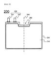
- FIG. 1 is a view typically showing the structure of a pouch-shaped secondary battery including a stacked type electrode assembly.
- a pouch-shaped secondary battery 10 is configured to have a structure in which an electrode assembly 30, including cathodes, anodes, and separators disposed respectively between the cathodes and the anodes, is mounted in a pouch-shaped battery case 20 in a sealed state such that two electrode leads 40 and 41 electrically connected to cathode and anode tabs 31 and 32 of the electrode assembly 30 are exposed to the outside.
- the battery case 20 includes a case body 21 having a depressed receiving part 23, in which the electrode assembly 30 is located, and a cover 22 integrally connected to the case body 21.
- the battery case 20 is made of a laminate sheet including an outer resin layer 20A constituting the outermost portion of the laminate sheet, an isolation metal layer 20B preventing penetration of materials, and an inner resin layer 20C for sealing.
- the cathode tabs 31 and the anode tabs 32 of the stacked type electrode assembly 30 are respectively coupled to the electrode leads 40 and 41 by welding.
- insulative films 50 are attached to the top and bottom of each of the electrode leads 40 and 41 to prevent the occurrence of a short circuit between a thermal welding device (not shown) and the electrode leads 40 and 41 and to secure sealing between the electrode leads 40 and 41 and the battery case 20 when the upper end 24 of the case body 21 and the upper end of the cover 22 are thermally welded to each other using the thermal welding device.
- the above-mentioned battery cells are configured to have the same size or the same capacity to constitute a battery pack. For this reason, in order to manufacture a lightweight and thin battery pack in consideration of the design of a device, to which the battery pack is applied, it is necessary to reduce the capacity of the battery pack or modify the design of the device such that the size of the device is increased. Furthermore, electrical connection is complicated during modification of the design of the device with the result that it is difficult to manufacture a battery pack satisfying desired conditions.
- the present invention has been made to solve the above problems, and other technical problems that have yet to be resolved.
- a battery cell configured to have a novel structure in which an electrode assembly that can be charged and discharged is mounted in a plate-shaped battery case, a cathode terminal and an anode terminal protrude from one end of the battery case such that the electrode terminals deviate to one side, and a depressed portion is formed at one side of the battery body, based on which battery cells having various capacities and sizes can be manufactured.
- a battery module including the above battery cells which is mounted in various spaces of a device to which the battery module is applied, whereby it is possible to maximally utilize an internal space of the device, the battery module may be mounted even in a space in which it is difficult to mount a conventional battery module as well as a narrow and small space, and it is possible to provide a battery cell having a novel structure based on which it is possible to design various types of battery modules and a battery module including the same.
- a battery cell configured to have a structure in which an electrode assembly that can be charged and discharged is mounted in a plate-shaped battery case, a cathode terminal and an anode terminal protrude from one end of the battery case, the electrode terminals deviate to one side from a vertical central axis of a battery body when viewed from above, and a depressed portion is formed at one side of the battery body.
- the battery cell according to the present invention is based on the specific structure as described above. Consequently, it is possible to manufacture battery cells having various capacities and sizes based on the battery cell according to the present invention.
- a battery module including the battery cell according to the present invention may be mounted in various spaces of a device to which the battery module is applied. Consequently, it is possible to maximally utilize an internal space of the device.
- the battery module according to the present invention may be mounted even in a space in which it is difficult to mount a conventional battery module as well as a narrow and small space. Consequently, it is possible to design various types of battery modules.
- the battery cell may be a lithium ion battery or a lithium ion polymer battery.
- the present invention is not limited thereto.
- the battery cell may be a thin battery generally having a small thickness.
- the battery cell may be a prismatic battery or a pouch-shaped battery.
- the battery case may be made of a laminate sheet including a metal layer and a resin layer.
- a representative example of the battery cell may be a pouch-shaped battery including a battery case made of a laminate sheet including aluminum and resin.
- the pouch-shaped battery may be configured to have a structure in which an electrode assembly of a cathode/separator/anode structure is mounted in a battery case in a state in which the electrode assembly is connected to electrode terminals protruding outward from the battery case.
- the metal layer may be made of an aluminum material.
- the electrode terminals deviate to one side from the vertical central axis of the battery body when viewed from above.
- the vertical central axis of the battery body when viewed from above means an axis passing just through the middle of the battery body in a vertical direction when viewed from above.
- a plurality of axes passing just through the middle of the battery body in the vertical direction may be provided.
- the axes may have the same length.
- the axes may be classified into a minor axis having a small length and a major axis having a larger length than the minor axis.
- the electrode terminals are located at one end of the battery cell on a minor axis thereof.
- the electrode terminals may deviate from a central axis of the battery body.
- a deviation degree of the electrode terminals may be changed depending upon various conditions.
- the electrode terminals may deviate from the central axis of the battery body to such an extent that the electrode terminals completely depart from the vertical central axis of the battery body when viewed from above.
- the expression “the electrode terminals completely depart from the vertical central axis of the battery body” may mean that the electrode terminals are formed in a state in which the electrode terminals are spaced apart from the vertical central axis of the battery body.
- each of the electrode terminals may have a width equivalent to 1/20 to 1/5 the width of the battery body although the width of each of the electrode terminals is not particularly restricted.
- the width of each of the electrode terminals is about 1/10 the width of the battery body and the electrode terminals deviate from the central axis of the battery body to such an extent that the electrode terminals completely depart from the vertical central axis of the battery body when viewed from above, it is possible to further increase the width of the depressed portion formed at one end of the battery body and to flexibly design the width of the depressed portion based on various shapes of the device to which the battery cell is applied.
- the depressed portion may be formed at the same side as one side of the battery body from which the electrode terminals protrude when viewed from above.
- the depressed portion may have a width equivalent to 1/5 to 1/2 the width of the battery body when viewed from above and a depth equivalent to 1/20 to 1/2 the length of the battery body when viewed from above although the width and depth of the depressed portion are not particularly restricted.
- the depressed portion may be symmetric with respect to the vertical central axis of the battery body when viewed from above.
- the width, depth, and symmetry of the depressed portion may be changed in design based on various conditions, such as the shape, inner space, and interference with other parts, of a device to which the battery cell is applied.
- the present invention provides a battery cell configured to have a structure in which an electrode assembly that can be charged and discharged is mounted in a plate-shaped battery case, a cathode terminal and an anode terminal protrude from one end of the battery case, the electrode terminals deviate to one side from a vertical central axis of a battery body when viewed from above, a depressed portion is formed at one side of the battery body, and the electrode assembly has a thickness increased in one direction in vertical section.
- the electrode assembly may be configured to have a structure in which two or more electrodes or unit cells having different planar sizes are stacked.
- Each of the unit cells may be a stacked type electrode assembly including a cathode, an anode, and a separator, the electrode assembly being configured to have a stacked structure in which the cathode and the anode are stacked in a state in which the separator is disposed between the cathode and the anode.
- the electrode assembly may be a combination type electrode assembly.
- the width, depth, and stacked structure of the depressed portion may be changed in design based on various conditions, such as the shape, inner space, and interference with other parts, of a device to which the battery cell is applied.
- the battery cell having the above-described structure may be flexibly designed and manufactured based on the shape and internal space of the device.
- a battery module including the battery cell with the above-stated construction as a unit battery, wherein the battery cell includes two or more battery cells.
- the battery module includes battery cells which are flexibly designed and manufactured based on the shape and internal space of a device. Consequently, the battery module according to the present invention has high inner space utilization and integration.
- the present invention provides a battery module configured to have a structure in which two or more unit batteries having different planar sizes or capacities are arranged in a plane, each of the unit batteries has electrode terminals deviating to one side from a vertical central axis of a battery body when viewed from above, and a depressed portion is formed at one side of the battery body.
- each of the unit batteries may include an electrode assembly that can be charged and discharged, the electrode assembly being mounted in a plate-shaped battery case, and the electrode terminals may protrude from one end of the battery case.
- the electrode terminals of the unit batteries may be electrically connected to each other via a cable, a bus bar, or a circuit board disposed at one side or opposite sides of each of the unit batteries.
- the battery module with the above-stated construction includes battery cells which are flexibly designed and manufactured based on the shape and internal space of a device. Consequently, the battery module according to the present invention has high inner space utilization and integration.
- a device including the battery module with the above-stated construction as a power source.
- the device may be selected from among a mobile phone, a portable computer, a smart phone, a tablet PC, a smart pad, a netbook computer, a light electronic vehicle (LEV), an electric vehicle, a hybrid electric vehicle, a plug-in hybrid electric vehicle, and a power storage device.
- LEV light electronic vehicle
- the structure of the device and a method of manufacturing the device are well known in the art to which the present invention pertains and, therefore, a detailed description thereof will be omitted.
- FIG. 2 is a plan view typically showing a battery cell according to an embodiment of the present invention.
- a battery cell 200 is configured to have a structure in which an electrode assembly 210 of a cathode/separator/anode structure is mounted in a pouch-shaped battery case 220.
- the battery cell 200 is configured to have a quadrangular plate-shaped structure. That is, the battery cell 100 is configured to have a thin rectangular parallelepiped structure when viewed three-dimensionally.
- a cathode terminal 231 and an anode terminal 232 protrude from one end of the battery case 220.
- the electrode terminals 231 and 232 deviate to one side from a vertical central axis 240 of the battery case 220 when viewed from above.
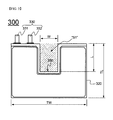
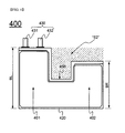
- FIGS. 3 and 4 are vertical sectional views showing battery cells according to other embodiments of the present invention.
- an area S1 of a depressed portion 350 formed at one side of a battery cell 300 may be flexibly changed in design based on a width W and a length L of the depressed portion 350.
- a depressed portion 450 is formed at one side of a battery cell 400.
- a battery case 420 is partitioned into a left case part 401 and a right case part 402.
- An area S2 of the depressed portion 450 formed based on lengths BL and BR of the left case part 401 and the right case part 402 may be flexibly changed in design based on conditions of a device to which the battery cell is applied.
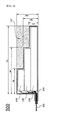
- FIG. 5 is a side view, in vertical section, showing a battery cell according to a further embodiment of the present invention.
- electrode assemblies 510, 520, and 530 having different lengths AL, BL, and CL and different capacities are mounted in a battery case 501 in a state in which the electrode assemblies 510, 520, and 530 are vertically stacked.
- the electrode assemblies 510, 520, and 530 which are vertically stacked are configured to have a structure in which the thickness of the vertically stacked electrode assemblies 510, 520, and 530 increases toward an electrode terminal 502 protruding outward from the battery case 501.
- the capacities of the electrode assemblies 510, 520, and 530 are proportional to the product of the lengths AL, BL, and CL, heights AH-BH, BH-CH, and CH, and widths (not shown) of the respective electrode assemblies 510, 520, and 530.
- a spare space S3 is defined at the right upper end of the battery cell 500 due to the electrode assemblies 510, 520, and 530 having different sizes.
- the spare space is inversely proportional to the lengths, the heights, and the widths of the electrode assemblies 510, 520, and 530.
- the spare space is provided to cope with conditions, such as an irregular inner space or interference with other parts, of a device to which the battery cell is applied.
- a thickness increase direction and a degree of stack thickness increase may also be flexibly changed in design based on applied conditions.
- FIG. 6 is a plan view typically showing a battery pack including battery cells according to an embodiment of the present invention.
- battery cells 610, 620, 630, and 640 are mounted on a circuit board 601.
- electrode terminals 611, 612, 621, and 622 of the respective battery cells 610, 620, 630, and 640 are electrically connected to one another or connected to external output terminals 603 and 604 via a circuit 602 formed on the circuit board 601.
- the two battery cells 610 and 620 are mounted at the left part of the circuit board 601 such that depressed portions 613 and 623 of the respective battery cells 610 and 620 are engaged with each other.
- the engagement-based structure is not achieved by conventional rectangular battery cells.
- the battery cells may be flexibly changed in design based on various conditions of the circuit board 601. Consequently, the battery module constituted by the battery cells according to the present invention has remarkably improved internal integration.
- the battery cells 630 and 640 are arranged at the right part of the circuit board 601 such that depressed portions 633 and 643 of the respective battery cells 630 and 640 are opposite to each other.
- a spare space S4 is defined by the two depressed portions 633 and 643.
- another spare space S5 is defined by a depressed portion 653 formed at a battery cell 650 arranged in vertical parallel.
- the upper and lower spare spaces S4 and S5 may be used as installation spaces for electronic circuit parts (not shown) or as spaces to avoid spatial interference with other parts.
- the battery pack including the battery cells according to the present invention may be flexibly changed in design based on conditions of a device to which the battery pack is applied, thereby achieving remarkably improved internal integration.
- a battery cell according to the present invention is configured to have a structure in which an electrode assembly that can be charged and discharged is mounted in a plate-shaped battery case, a cathode terminal and an anode terminal protrude from one end of the battery case such that the cathode terminal and the anode terminal deviate to one side, and a depressed portion is formed at one side of a battery body. Consequently, it is possible to manufacture battery cells having various capacities and sizes.
- a battery module including the above battery cells according to the present invention may be mounted in various spaces of a device to which the battery module is applied. Consequently, it is possible to maximally utilize an internal space of the device. Furthermore, the battery module according to the present invention may be mounted even in a space in which it is difficult to mount a conventional battery module as well as a narrow and small space. Consequently, it is possible to provide a battery cell having a novel structure based on which it is possible to design various types of battery modules and a battery module including the same.
Applications Claiming Priority (2)
| Application Number | Priority Date | Filing Date | Title |
|---|---|---|---|
| KR1020120047854A KR101403388B1 (ko) | 2012-05-07 | 2012-05-07 | 비정형 구조의 전지셀 및 이를 포함하는 전지모듈 |
| PCT/KR2013/003930 WO2013168948A1 (fr) | 2012-05-07 | 2013-05-07 | Elément de batterie présentant une structure amorphe et module de batterie le comprenant |
Publications (3)
| Publication Number | Publication Date |
|---|---|
| EP2849262A1 true EP2849262A1 (fr) | 2015-03-18 |
| EP2849262A4 EP2849262A4 (fr) | 2015-12-16 |
| EP2849262B1 EP2849262B1 (fr) | 2017-07-05 |
Family
ID=49550928
Family Applications (1)
| Application Number | Title | Priority Date | Filing Date |
|---|---|---|---|
| EP13787997.9A Active EP2849262B1 (fr) | 2012-05-07 | 2013-05-07 | Elément de batterie présentant une structure irreguliere et module de batterie le comprenant |
Country Status (6)
| Country | Link |
|---|---|
| US (1) | US9548475B2 (fr) |
| EP (1) | EP2849262B1 (fr) |
| JP (1) | JP6112579B2 (fr) |
| KR (1) | KR101403388B1 (fr) |
| CN (1) | CN104247094B (fr) |
| WO (1) | WO2013168948A1 (fr) |
Cited By (2)
| Publication number | Priority date | Publication date | Assignee | Title |
|---|---|---|---|---|
| EP2927986A4 (fr) * | 2013-03-04 | 2015-12-16 | Lg Chemical Ltd | Cellule de batterie ayant une partie manquante et bloc-batterie comprenant celle-ci |
| TWI643387B (zh) * | 2015-11-30 | 2018-12-01 | 南韓商Lg化學股份有限公司 | 具有改善密封可靠性的電池盒的不規則結構的電池單元 |
Families Citing this family (24)
| Publication number | Priority date | Publication date | Assignee | Title |
|---|---|---|---|---|
| KR101590979B1 (ko) * | 2014-03-18 | 2016-02-03 | 주식회사 엘지화학 | 비대칭 구조 및 만입 구조를 포함하는 전지셀 |
| KR101723035B1 (ko) * | 2014-10-22 | 2017-04-04 | 주식회사 엘지화학 | 가스 센서를 포함하는 전지셀 |
| WO2016085020A1 (fr) * | 2014-11-25 | 2016-06-02 | 엘지전자 주식회사 | Dispositif d'affichage portable |
| WO2016092889A1 (fr) * | 2014-12-09 | 2016-06-16 | 日本碍子株式会社 | Dispositif équipé d'une batterie |
| KR20160108115A (ko) * | 2015-03-04 | 2016-09-19 | 주식회사 엘지화학 | 전극 리드를 통한 전기 연결 구조를 효율적으로 구성할 수 있는 비정형 구조의 전지셀 |
| KR101800932B1 (ko) * | 2015-03-16 | 2017-11-23 | 주식회사 엘지화학 | 스텝드 배터리 |
| WO2016195438A1 (fr) * | 2015-06-04 | 2016-12-08 | 주식회사 엘지화학 | Élément de batterie, et module de batterie et bloc-batterie le comprenant |
| KR101994842B1 (ko) * | 2015-07-27 | 2019-07-01 | 주식회사 엘지화학 | 내부 공간 활용을 극대화할 수 있는 구조의 전극판 및 이를 포함하는 이차전지 또는 캐패시터 |
| KR101826142B1 (ko) | 2015-08-27 | 2018-02-07 | 삼성에스디아이 주식회사 | 전극 조립체 및 그 제조 방법과 이차 전지 |
| KR102107000B1 (ko) | 2015-12-14 | 2020-05-06 | 주식회사 엘지화학 | 전극판에 만입부가 형성되어 있는 전극조립체 및 이를 포함하는 이차전지 |
| KR102082655B1 (ko) * | 2015-12-17 | 2020-02-28 | 주식회사 엘지화학 | 모서리가 절취되어 있는 구조의 전극조립체 제조방법 및 이를 사용하여 제조되는 전극조립체 |
| CN109196704A (zh) * | 2016-05-31 | 2019-01-11 | 株式会社村田制作所 | 蓄电设备 |
| CN110121797B (zh) | 2017-01-12 | 2022-06-24 | 株式会社村田制作所 | 二次电池 |
| KR102125531B1 (ko) | 2017-02-14 | 2020-06-30 | 주식회사 엘지화학 | 수평방향의 상보적인 패턴을 가지는 전극들을 포함하는 캐패시터 |
| WO2018211941A1 (fr) * | 2017-05-19 | 2018-11-22 | 株式会社村田製作所 | Accumulateur et son procédé de fabrication |
| JP6866922B2 (ja) * | 2017-06-01 | 2021-04-28 | 株式会社村田製作所 | 二次電池の製造方法 |
| WO2019044615A1 (fr) * | 2017-08-31 | 2019-03-07 | 株式会社村田製作所 | Dispositif accumulateur de puissance |
| US10673038B2 (en) * | 2018-03-23 | 2020-06-02 | Chongqing Jinkang New Energy Vehicle Co., Ltd. | Battery cells for battery packs in electric vehicles |
| KR102351248B1 (ko) | 2018-12-10 | 2022-01-17 | 주식회사 엘지에너지솔루션 | 이차전지용 케이스, 이차전지 및 전지 모듈 |
| KR102372383B1 (ko) * | 2018-12-26 | 2022-03-07 | 주식회사 엘지에너지솔루션 | 에너지 밀도가 향상된 구조를 갖는 배터리 모듈, 이를 포함하는 배터리 팩 및 자동차 |
| CN109786844B (zh) * | 2019-01-22 | 2021-05-04 | 华为技术有限公司 | 一种电池及其封装方法和终端 |
| CN109904355A (zh) * | 2019-03-08 | 2019-06-18 | 易佰特新能源科技有限公司 | 一种异形锂离子电池及其制造方法 |
| CN117594855A (zh) * | 2021-02-09 | 2024-02-23 | 荣耀终端有限公司 | 电池和电子设备 |
| WO2023063330A1 (fr) * | 2021-10-13 | 2023-04-20 | 株式会社Gsユアサ | Élément de stockage d'énergie |
Family Cites Families (16)
| Publication number | Priority date | Publication date | Assignee | Title |
|---|---|---|---|---|
| US6040078A (en) * | 1997-03-06 | 2000-03-21 | Mitsubishi Chemical Corporation | Free form battery apparatus |
| JP2000133317A (ja) * | 1998-10-26 | 2000-05-12 | Mitsubishi Chemicals Corp | 自由形状電池装置 |
| JP4273369B2 (ja) * | 1999-06-14 | 2009-06-03 | 株式会社ジーエス・ユアサコーポレーション | 枠付き電池 |
| KR100440934B1 (ko) * | 2002-02-06 | 2004-07-21 | 삼성에스디아이 주식회사 | 이차전지 |
| JP2005038613A (ja) * | 2003-07-15 | 2005-02-10 | Ngk Spark Plug Co Ltd | 板型電池 |
| KR100896134B1 (ko) * | 2005-06-23 | 2009-05-08 | 주식회사 엘지화학 | 편향된 양방향 전극단자를 가지고 있는 전지 및 이를포함하고 있는 전지모듈 |
| JP4208865B2 (ja) * | 2005-07-07 | 2009-01-14 | 株式会社東芝 | 非水電解質電池及び電池パック |
| WO2008023903A1 (fr) * | 2006-08-21 | 2008-02-28 | Lg Chem, Ltd. | Accumulateur secondaire de type poche présentant des propriétés de sécurité améliorées et une excellente aptitude au traitement |
| KR101023870B1 (ko) * | 2009-01-08 | 2011-03-22 | 삼성에스디아이 주식회사 | 파우치형 리튬 이차전지 |
| KR20100109842A (ko) * | 2009-04-01 | 2010-10-11 | 주식회사 엘지화학 | 지지부재를 포함하고 있는 이차전지 |
| KR101040826B1 (ko) | 2009-09-28 | 2011-06-14 | 삼성에스디아이 주식회사 | 이차전지 |
| KR101154872B1 (ko) * | 2010-01-12 | 2012-06-18 | 주식회사 엘지화학 | 신규한 구조의 전극조립체 |
| CN103098256B (zh) * | 2010-03-19 | 2016-01-20 | 株式会社Lg化学 | 袋式壳体和包括该袋式壳体的电池组 |
| US9040187B2 (en) * | 2010-07-13 | 2015-05-26 | Apple, Inc. | Battery pack with cells of different capacities electrically coupled in parallel |
| US8940429B2 (en) * | 2010-07-16 | 2015-01-27 | Apple Inc. | Construction of non-rectangular batteries |
| US20140113184A1 (en) * | 2012-10-18 | 2014-04-24 | Apple Inc. | Three-dimensional non-rectangular battery cell structures |
-
2012
- 2012-05-07 KR KR1020120047854A patent/KR101403388B1/ko active IP Right Grant
-
2013
- 2013-05-07 WO PCT/KR2013/003930 patent/WO2013168948A1/fr active Application Filing
- 2013-05-07 JP JP2015508878A patent/JP6112579B2/ja active Active
- 2013-05-07 CN CN201380021763.8A patent/CN104247094B/zh active Active
- 2013-05-07 EP EP13787997.9A patent/EP2849262B1/fr active Active
-
2014
- 2014-10-16 US US14/515,848 patent/US9548475B2/en active Active
Cited By (3)
| Publication number | Priority date | Publication date | Assignee | Title |
|---|---|---|---|---|
| EP2927986A4 (fr) * | 2013-03-04 | 2015-12-16 | Lg Chemical Ltd | Cellule de batterie ayant une partie manquante et bloc-batterie comprenant celle-ci |
| TWI643387B (zh) * | 2015-11-30 | 2018-12-01 | 南韓商Lg化學股份有限公司 | 具有改善密封可靠性的電池盒的不規則結構的電池單元 |
| US10790478B2 (en) | 2015-11-30 | 2020-09-29 | Lg Chem, Ltd. | Battery cell of irregular structure with improved sealing reliability of cell case |
Also Published As
| Publication number | Publication date |
|---|---|
| EP2849262B1 (fr) | 2017-07-05 |
| CN104247094A (zh) | 2014-12-24 |
| WO2013168948A1 (fr) | 2013-11-14 |
| JP6112579B2 (ja) | 2017-04-12 |
| JP2015518256A (ja) | 2015-06-25 |
| KR101403388B1 (ko) | 2014-06-03 |
| US20150037664A1 (en) | 2015-02-05 |
| KR20130124622A (ko) | 2013-11-15 |
| US9548475B2 (en) | 2017-01-17 |
| CN104247094B (zh) | 2017-06-13 |
| EP2849262A4 (fr) | 2015-12-16 |
Similar Documents
| Publication | Publication Date | Title |
|---|---|---|
| US9548475B2 (en) | Battery cell of irregular structure and battery module employed with the same | |
| EP3151307B1 (fr) | Module de batterie et bloc-batterie le comprenant | |
| US10056577B2 (en) | Battery cell of novel structure | |
| EP2562842B1 (fr) | Module de batterie | |
| KR102052588B1 (ko) | 이차전지 팩 | |
| KR101402657B1 (ko) | 비정형 구조의 전지팩 | |
| KR101754613B1 (ko) | 전극 어셈블리의 고정구조를 포함하는 이차 전지 | |
| KR20150134304A (ko) | 라운드 코너를 포함하는 전지셀 | |
| EP2958177B1 (fr) | Ensemble électrode à coins arrondis | |
| KR101440890B1 (ko) | 전지 팩 | |
| KR20140100032A (ko) | 단차 구조를 포함하는 전지셀 | |
| KR102332343B1 (ko) | 전지 모듈 | |
| US9786874B2 (en) | Electrode having round corner | |
| KR20150133165A (ko) | 단차 구조를 포함하는 전지셀 | |
| KR101763265B1 (ko) | 계단 구조의 전극조립체에 대응하는 트리밍부가 형성되어 있는 전지케이스를 포함하는 전지셀 | |
| KR101580086B1 (ko) | 복합 구조로 형성된 전극조립체 | |
| US9012059B2 (en) | Secondary battery | |
| KR101725903B1 (ko) | 계단 구조의 전극조립체에 대응하는 돌출부가 형성되어 있는 전지케이스를 포함하는 전지셀 | |
| KR20150025207A (ko) | 리튬 이차전지 및 이를 포함하는 전지팩 | |
| KR20170014476A (ko) | 원형 전극을 포함하는 원통형 이차전지 | |
| KR20210076770A (ko) | 이차 전지용 전지 케이스 및 파우치 형 이차 전지 | |
| KR102576583B1 (ko) | 배터리 셀 | |
| EP2916365A1 (fr) | Dispositif électrique comprenant un coin arrondi | |
| KR20160054268A (ko) | 이차전지셀 및 이를 포함하는 배터리 모듈 | |
| KR101876614B1 (ko) | 복합 구조로 형성된 전극조립체 |
Legal Events
| Date | Code | Title | Description |
|---|---|---|---|
| PUAI | Public reference made under article 153(3) epc to a published international application that has entered the european phase |
Free format text: ORIGINAL CODE: 0009012 |
|
| 17P | Request for examination filed |
Effective date: 20141022 |
|
| AK | Designated contracting states |
Kind code of ref document: A1 Designated state(s): AL AT BE BG CH CY CZ DE DK EE ES FI FR GB GR HR HU IE IS IT LI LT LU LV MC MK MT NL NO PL PT RO RS SE SI SK SM TR |
|
| AX | Request for extension of the european patent |
Extension state: BA ME |
|
| DAX | Request for extension of the european patent (deleted) | ||
| RA4 | Supplementary search report drawn up and despatched (corrected) |
Effective date: 20151118 |
|
| RIC1 | Information provided on ipc code assigned before grant |
Ipc: H01M 2/30 20060101ALI20151112BHEP Ipc: H01M 10/0525 20100101ALN20151112BHEP Ipc: H01M 2/26 20060101ALI20151112BHEP Ipc: H01M 2/02 20060101AFI20151112BHEP |
|
| 17Q | First examination report despatched |
Effective date: 20160819 |
|
| REG | Reference to a national code |
Ref country code: DE Ref legal event code: R079 Ref document number: 602013023171 Country of ref document: DE Free format text: PREVIOUS MAIN CLASS: H01M0002260000 Ipc: H01M0002020000 |
|
| GRAP | Despatch of communication of intention to grant a patent |
Free format text: ORIGINAL CODE: EPIDOSNIGR1 |
|
| RIC1 | Information provided on ipc code assigned before grant |
Ipc: H01M 10/0525 20100101ALN20170125BHEP Ipc: H01M 2/02 20060101AFI20170125BHEP Ipc: H01M 2/26 20060101ALI20170125BHEP Ipc: H01M 2/30 20060101ALI20170125BHEP |
|
| INTG | Intention to grant announced |
Effective date: 20170208 |
|
| RIN1 | Information on inventor provided before grant (corrected) |
Inventor name: KWON, SUNGJIN Inventor name: KIM, KI WOONG Inventor name: JUNG, HYUN CHUL Inventor name: KANG, KYOUNG WON |
|
| GRAS | Grant fee paid |
Free format text: ORIGINAL CODE: EPIDOSNIGR3 |
|
| GRAA | (expected) grant |
Free format text: ORIGINAL CODE: 0009210 |
|
| AK | Designated contracting states |
Kind code of ref document: B1 Designated state(s): AL AT BE BG CH CY CZ DE DK EE ES FI FR GB GR HR HU IE IS IT LI LT LU LV MC MK MT NL NO PL PT RO RS SE SI SK SM TR |
|
| REG | Reference to a national code |
Ref country code: GB Ref legal event code: FG4D |
|
| REG | Reference to a national code |
Ref country code: CH Ref legal event code: EP |
|
| REG | Reference to a national code |
Ref country code: AT Ref legal event code: REF Ref document number: 907158 Country of ref document: AT Kind code of ref document: T Effective date: 20170715 |
|
| REG | Reference to a national code |
Ref country code: IE Ref legal event code: FG4D |
|
| REG | Reference to a national code |
Ref country code: DE Ref legal event code: R096 Ref document number: 602013023171 Country of ref document: DE |
|
| REG | Reference to a national code |
Ref country code: NL Ref legal event code: MP Effective date: 20170705 |
|
| REG | Reference to a national code |
Ref country code: AT Ref legal event code: MK05 Ref document number: 907158 Country of ref document: AT Kind code of ref document: T Effective date: 20170705 |
|
| REG | Reference to a national code |
Ref country code: LT Ref legal event code: MG4D |
|
| PG25 | Lapsed in a contracting state [announced via postgrant information from national office to epo] |
Ref country code: HR Free format text: LAPSE BECAUSE OF FAILURE TO SUBMIT A TRANSLATION OF THE DESCRIPTION OR TO PAY THE FEE WITHIN THE PRESCRIBED TIME-LIMIT Effective date: 20170705 Ref country code: LT Free format text: LAPSE BECAUSE OF FAILURE TO SUBMIT A TRANSLATION OF THE DESCRIPTION OR TO PAY THE FEE WITHIN THE PRESCRIBED TIME-LIMIT Effective date: 20170705 Ref country code: AT Free format text: LAPSE BECAUSE OF FAILURE TO SUBMIT A TRANSLATION OF THE DESCRIPTION OR TO PAY THE FEE WITHIN THE PRESCRIBED TIME-LIMIT Effective date: 20170705 Ref country code: NO Free format text: LAPSE BECAUSE OF FAILURE TO SUBMIT A TRANSLATION OF THE DESCRIPTION OR TO PAY THE FEE WITHIN THE PRESCRIBED TIME-LIMIT Effective date: 20171005 Ref country code: SE Free format text: LAPSE BECAUSE OF FAILURE TO SUBMIT A TRANSLATION OF THE DESCRIPTION OR TO PAY THE FEE WITHIN THE PRESCRIBED TIME-LIMIT Effective date: 20170705 Ref country code: NL Free format text: LAPSE BECAUSE OF FAILURE TO SUBMIT A TRANSLATION OF THE DESCRIPTION OR TO PAY THE FEE WITHIN THE PRESCRIBED TIME-LIMIT Effective date: 20170705 Ref country code: FI Free format text: LAPSE BECAUSE OF FAILURE TO SUBMIT A TRANSLATION OF THE DESCRIPTION OR TO PAY THE FEE WITHIN THE PRESCRIBED TIME-LIMIT Effective date: 20170705 |
|
| PG25 | Lapsed in a contracting state [announced via postgrant information from national office to epo] |
Ref country code: LV Free format text: LAPSE BECAUSE OF FAILURE TO SUBMIT A TRANSLATION OF THE DESCRIPTION OR TO PAY THE FEE WITHIN THE PRESCRIBED TIME-LIMIT Effective date: 20170705 Ref country code: ES Free format text: LAPSE BECAUSE OF FAILURE TO SUBMIT A TRANSLATION OF THE DESCRIPTION OR TO PAY THE FEE WITHIN THE PRESCRIBED TIME-LIMIT Effective date: 20170705 Ref country code: BG Free format text: LAPSE BECAUSE OF FAILURE TO SUBMIT A TRANSLATION OF THE DESCRIPTION OR TO PAY THE FEE WITHIN THE PRESCRIBED TIME-LIMIT Effective date: 20171005 Ref country code: RS Free format text: LAPSE BECAUSE OF FAILURE TO SUBMIT A TRANSLATION OF THE DESCRIPTION OR TO PAY THE FEE WITHIN THE PRESCRIBED TIME-LIMIT Effective date: 20170705 Ref country code: GR Free format text: LAPSE BECAUSE OF FAILURE TO SUBMIT A TRANSLATION OF THE DESCRIPTION OR TO PAY THE FEE WITHIN THE PRESCRIBED TIME-LIMIT Effective date: 20171006 Ref country code: IS Free format text: LAPSE BECAUSE OF FAILURE TO SUBMIT A TRANSLATION OF THE DESCRIPTION OR TO PAY THE FEE WITHIN THE PRESCRIBED TIME-LIMIT Effective date: 20171105 Ref country code: PL Free format text: LAPSE BECAUSE OF FAILURE TO SUBMIT A TRANSLATION OF THE DESCRIPTION OR TO PAY THE FEE WITHIN THE PRESCRIBED TIME-LIMIT Effective date: 20170705 |
|
| REG | Reference to a national code |
Ref country code: DE Ref legal event code: R097 Ref document number: 602013023171 Country of ref document: DE |
|
| REG | Reference to a national code |
Ref country code: FR Ref legal event code: PLFP Year of fee payment: 6 |
|
| PG25 | Lapsed in a contracting state [announced via postgrant information from national office to epo] |
Ref country code: RO Free format text: LAPSE BECAUSE OF FAILURE TO SUBMIT A TRANSLATION OF THE DESCRIPTION OR TO PAY THE FEE WITHIN THE PRESCRIBED TIME-LIMIT Effective date: 20170705 Ref country code: DK Free format text: LAPSE BECAUSE OF FAILURE TO SUBMIT A TRANSLATION OF THE DESCRIPTION OR TO PAY THE FEE WITHIN THE PRESCRIBED TIME-LIMIT Effective date: 20170705 Ref country code: CZ Free format text: LAPSE BECAUSE OF FAILURE TO SUBMIT A TRANSLATION OF THE DESCRIPTION OR TO PAY THE FEE WITHIN THE PRESCRIBED TIME-LIMIT Effective date: 20170705 |
|
| PLBE | No opposition filed within time limit |
Free format text: ORIGINAL CODE: 0009261 |
|
| STAA | Information on the status of an ep patent application or granted ep patent |
Free format text: STATUS: NO OPPOSITION FILED WITHIN TIME LIMIT |
|
| PG25 | Lapsed in a contracting state [announced via postgrant information from national office to epo] |
Ref country code: SM Free format text: LAPSE BECAUSE OF FAILURE TO SUBMIT A TRANSLATION OF THE DESCRIPTION OR TO PAY THE FEE WITHIN THE PRESCRIBED TIME-LIMIT Effective date: 20170705 Ref country code: EE Free format text: LAPSE BECAUSE OF FAILURE TO SUBMIT A TRANSLATION OF THE DESCRIPTION OR TO PAY THE FEE WITHIN THE PRESCRIBED TIME-LIMIT Effective date: 20170705 Ref country code: SK Free format text: LAPSE BECAUSE OF FAILURE TO SUBMIT A TRANSLATION OF THE DESCRIPTION OR TO PAY THE FEE WITHIN THE PRESCRIBED TIME-LIMIT Effective date: 20170705 Ref country code: IT Free format text: LAPSE BECAUSE OF FAILURE TO SUBMIT A TRANSLATION OF THE DESCRIPTION OR TO PAY THE FEE WITHIN THE PRESCRIBED TIME-LIMIT Effective date: 20170705 |
|
| 26N | No opposition filed |
Effective date: 20180406 |
|
| PG25 | Lapsed in a contracting state [announced via postgrant information from national office to epo] |
Ref country code: SI Free format text: LAPSE BECAUSE OF FAILURE TO SUBMIT A TRANSLATION OF THE DESCRIPTION OR TO PAY THE FEE WITHIN THE PRESCRIBED TIME-LIMIT Effective date: 20170705 |
|
| REG | Reference to a national code |
Ref country code: CH Ref legal event code: PL |
|
| REG | Reference to a national code |
Ref country code: BE Ref legal event code: MM Effective date: 20180531 |
|
| PG25 | Lapsed in a contracting state [announced via postgrant information from national office to epo] |
Ref country code: MC Free format text: LAPSE BECAUSE OF FAILURE TO SUBMIT A TRANSLATION OF THE DESCRIPTION OR TO PAY THE FEE WITHIN THE PRESCRIBED TIME-LIMIT Effective date: 20170705 |
|
| REG | Reference to a national code |
Ref country code: IE Ref legal event code: MM4A |
|
| PG25 | Lapsed in a contracting state [announced via postgrant information from national office to epo] |
Ref country code: CH Free format text: LAPSE BECAUSE OF NON-PAYMENT OF DUE FEES Effective date: 20180531 Ref country code: LI Free format text: LAPSE BECAUSE OF NON-PAYMENT OF DUE FEES Effective date: 20180531 |
|
| PG25 | Lapsed in a contracting state [announced via postgrant information from national office to epo] |
Ref country code: LU Free format text: LAPSE BECAUSE OF NON-PAYMENT OF DUE FEES Effective date: 20180507 |
|
| PG25 | Lapsed in a contracting state [announced via postgrant information from national office to epo] |
Ref country code: IE Free format text: LAPSE BECAUSE OF NON-PAYMENT OF DUE FEES Effective date: 20180507 |
|
| PG25 | Lapsed in a contracting state [announced via postgrant information from national office to epo] |
Ref country code: BE Free format text: LAPSE BECAUSE OF NON-PAYMENT OF DUE FEES Effective date: 20180531 |
|
| PG25 | Lapsed in a contracting state [announced via postgrant information from national office to epo] |
Ref country code: MT Free format text: LAPSE BECAUSE OF NON-PAYMENT OF DUE FEES Effective date: 20180507 |
|
| PG25 | Lapsed in a contracting state [announced via postgrant information from national office to epo] |
Ref country code: TR Free format text: LAPSE BECAUSE OF FAILURE TO SUBMIT A TRANSLATION OF THE DESCRIPTION OR TO PAY THE FEE WITHIN THE PRESCRIBED TIME-LIMIT Effective date: 20170705 |
|
| PG25 | Lapsed in a contracting state [announced via postgrant information from national office to epo] |
Ref country code: PT Free format text: LAPSE BECAUSE OF FAILURE TO SUBMIT A TRANSLATION OF THE DESCRIPTION OR TO PAY THE FEE WITHIN THE PRESCRIBED TIME-LIMIT Effective date: 20170705 Ref country code: HU Free format text: LAPSE BECAUSE OF FAILURE TO SUBMIT A TRANSLATION OF THE DESCRIPTION OR TO PAY THE FEE WITHIN THE PRESCRIBED TIME-LIMIT; INVALID AB INITIO Effective date: 20130507 |
|
| PG25 | Lapsed in a contracting state [announced via postgrant information from national office to epo] |
Ref country code: CY Free format text: LAPSE BECAUSE OF FAILURE TO SUBMIT A TRANSLATION OF THE DESCRIPTION OR TO PAY THE FEE WITHIN THE PRESCRIBED TIME-LIMIT Effective date: 20170705 Ref country code: MK Free format text: LAPSE BECAUSE OF NON-PAYMENT OF DUE FEES Effective date: 20170705 |
|
| PG25 | Lapsed in a contracting state [announced via postgrant information from national office to epo] |
Ref country code: AL Free format text: LAPSE BECAUSE OF FAILURE TO SUBMIT A TRANSLATION OF THE DESCRIPTION OR TO PAY THE FEE WITHIN THE PRESCRIBED TIME-LIMIT Effective date: 20170705 |
|
| REG | Reference to a national code |
Ref country code: DE Ref legal event code: R079 Ref document number: 602013023171 Country of ref document: DE Free format text: PREVIOUS MAIN CLASS: H01M0002020000 Ipc: H01M0050100000 |
|
| P01 | Opt-out of the competence of the unified patent court (upc) registered |
Effective date: 20230408 |
|
| PGFP | Annual fee paid to national office [announced via postgrant information from national office to epo] |
Ref country code: FR Payment date: 20230420 Year of fee payment: 11 Ref country code: DE Payment date: 20230420 Year of fee payment: 11 |
|
| REG | Reference to a national code |
Ref country code: GB Ref legal event code: 732E Free format text: REGISTERED BETWEEN 20230824 AND 20230831 |
|
| PGFP | Annual fee paid to national office [announced via postgrant information from national office to epo] |
Ref country code: GB Payment date: 20230420 Year of fee payment: 11 |
|
| REG | Reference to a national code |
Ref country code: DE Ref legal event code: R081 Ref document number: 602013023171 Country of ref document: DE Owner name: LG ENERGY SOLUTION, LTD., KR Free format text: FORMER OWNER: LG CHEM, LTD., SEOUL, KR |