EP2849260A1 - Wiederaufladbare Batterie - Google Patents
Wiederaufladbare Batterie Download PDFInfo
- Publication number
- EP2849260A1 EP2849260A1 EP14183877.1A EP14183877A EP2849260A1 EP 2849260 A1 EP2849260 A1 EP 2849260A1 EP 14183877 A EP14183877 A EP 14183877A EP 2849260 A1 EP2849260 A1 EP 2849260A1
- Authority
- EP
- European Patent Office
- Prior art keywords
- battery
- contact
- water
- separating means
- film separating
- Prior art date
- Legal status (The legal status is an assumption and is not a legal conclusion. Google has not performed a legal analysis and makes no representation as to the accuracy of the status listed.)
- Granted
Links
Images




Classifications
-
- H—ELECTRICITY
- H01—ELECTRIC ELEMENTS
- H01M—PROCESSES OR MEANS, e.g. BATTERIES, FOR THE DIRECT CONVERSION OF CHEMICAL ENERGY INTO ELECTRICAL ENERGY
- H01M50/00—Constructional details or processes of manufacture of the non-active parts of electrochemical cells other than fuel cells, e.g. hybrid cells
- H01M50/20—Mountings; Secondary casings or frames; Racks, modules or packs; Suspension devices; Shock absorbers; Transport or carrying devices; Holders
- H01M50/204—Racks, modules or packs for multiple batteries or multiple cells
- H01M50/207—Racks, modules or packs for multiple batteries or multiple cells characterised by their shape
- H01M50/213—Racks, modules or packs for multiple batteries or multiple cells characterised by their shape adapted for cells having curved cross-section, e.g. round or elliptic
-
- H—ELECTRICITY
- H02—GENERATION; CONVERSION OR DISTRIBUTION OF ELECTRIC POWER
- H02J—ELECTRIC POWER NETWORKS; CIRCUIT ARRANGEMENTS OR SYSTEMS FOR SUPPLYING OR DISTRIBUTING ELECTRIC POWER; SYSTEMS FOR STORING ELECTRIC ENERGY
- H02J7/00—Circuit arrangements for charging or discharging batteries or for supplying loads from batteries
- H02J7/70—Circuit arrangements for charging or discharging batteries or for supplying loads from batteries characterised by the mechanical construction
- H02J7/751—Circuit arrangements for charging or discharging batteries or for supplying loads from batteries characterised by the mechanical construction concerning the insertion or the connection of the batteries
-
- H—ELECTRICITY
- H01—ELECTRIC ELEMENTS
- H01M—PROCESSES OR MEANS, e.g. BATTERIES, FOR THE DIRECT CONVERSION OF CHEMICAL ENERGY INTO ELECTRICAL ENERGY
- H01M50/00—Constructional details or processes of manufacture of the non-active parts of electrochemical cells other than fuel cells, e.g. hybrid cells
- H01M50/20—Mountings; Secondary casings or frames; Racks, modules or packs; Suspension devices; Shock absorbers; Transport or carrying devices; Holders
- H01M50/296—Mountings; Secondary casings or frames; Racks, modules or packs; Suspension devices; Shock absorbers; Transport or carrying devices; Holders characterised by terminals of battery packs
-
- H—ELECTRICITY
- H01—ELECTRIC ELEMENTS
- H01M—PROCESSES OR MEANS, e.g. BATTERIES, FOR THE DIRECT CONVERSION OF CHEMICAL ENERGY INTO ELECTRICAL ENERGY
- H01M50/00—Constructional details or processes of manufacture of the non-active parts of electrochemical cells other than fuel cells, e.g. hybrid cells
- H01M50/50—Current conducting connections for cells or batteries
-
- Y—GENERAL TAGGING OF NEW TECHNOLOGICAL DEVELOPMENTS; GENERAL TAGGING OF CROSS-SECTIONAL TECHNOLOGIES SPANNING OVER SEVERAL SECTIONS OF THE IPC; TECHNICAL SUBJECTS COVERED BY FORMER USPC CROSS-REFERENCE ART COLLECTIONS [XRACs] AND DIGESTS
- Y02—TECHNOLOGIES OR APPLICATIONS FOR MITIGATION OR ADAPTATION AGAINST CLIMATE CHANGE
- Y02E—REDUCTION OF GREENHOUSE GAS [GHG] EMISSIONS, RELATED TO ENERGY GENERATION, TRANSMISSION OR DISTRIBUTION
- Y02E60/00—Enabling technologies; Technologies with a potential or indirect contribution to GHG emissions mitigation
- Y02E60/10—Energy storage using batteries
Definitions
- the invention is based on a battery device, in particular tool battery device, with a sealing device which is provided to at least dustproof and / or watertight seal at least one electrical area, with a first electrical contact and at least a second electrical contact, which are provided to a electrical operating energy and / or transmit information.
- the rechargeable battery device has at least one water-film separating means which is intended to prevent a formation of a direct water film between the first contact and the second contact, in particular when water enters in at least one operating state.
- a “sealing device” is to be understood, in particular, as a device which appears appropriate to a person skilled in the art and which is suitable for preventing penetration of dust and / or moisture into the cell block.
- the sealing device prevents penetration of dust and / or moisture into one in particular substantially entire area between the battery cells of the cell block.
- a “sealing device” should not be understood to mean a device which seals or electrically insulates a single battery cell.
- an "electrical area” is to be understood as an area in which an electrical system and / or electronics are at least partially arranged.
- an electrical system except for the contacts, in particular electronics, is arranged at least substantially completely in the electrical area.
- only the electrical contacts are arranged outside the electrical area.
- the electrical system preferably comprises rechargeable battery cells, electrical connection means and electronics of the rechargeable battery.
- at least one cell block and advantageously the electronics are arranged in the electrical area.
- a "cell block” is to be understood, in particular, as a unit having a plurality of rechargeable batteries, which are intended to deliver an electrical energy, in particular to a tool.
- the cell block comprises at least two rechargeable battery cells, advantageously at least eight rechargeable battery cells, particularly advantageously at least 16 battery cells.
- the battery cells are arranged stationary relative to each other.
- a heat dissipation means of the cell block arranges the battery cells relative to one another.
- the cell block has a cell block housing, which is intended to fasten the heat dissipation means and, advantageously, the battery cells to one another.
- the cell block forms an assembly at least during an assembly step.
- the cell block is provided to provide an electrical energy having a voltage greater than 12 volts, more preferably greater than 20 volts.
- the cell block is intended to provide electrical energy with a voltage less than 50 volts.
- the cell block, and thus the battery has a storage capacity of less than 1000 watt-hours, advantageously less than 500 watt-hours, particularly advantageously less than 250 watt-hours.
- the cell block, and thus the rechargeable battery has a storage capacity of more than 10 watt-hours, advantageously more than 25 watt-hours, particularly advantageously more than 100 watt-hours.
- an “electronics” is to be understood in particular as meaning a device which influences at least one electric current in a gas, in a conductor, in a vacuum and / or advantageously in a semiconductor.
- the electronics preferably have at least one transistor, more preferably at least one microprocessor.
- the sealing device prevents ingress of water and / or dust into the cell block
- the sealing device protects the cell block according to the standard IEC 60529 at least with the protection class IP55, preferably IP 67, particularly preferably IP 68.
- electrical contacts of the rechargeable battery are arranged in a region which lies outside a region protected by the sealing device It is intended to transmit energy and / or information to a tool connected to the tool interface of the rechargeable battery,
- the contact has a contact tulip or a contact pin,
- an electrical energy should be generated under an "electrical operating energy” be provided, which is intended to carry out an intended main function of the tool.
- a "water-film separating agent” is to be understood as meaning a means which is intended to prevent a malfunction of water between the electrical contacts.
- the water film separating means interrupts a direct water film between the electrical contacts in at least one operating state.
- the water film separating means is provided to prevent a connection between two water films, each touching one of the contacts.
- the water film separating agent separates the water film, at least when an area between the contacts is emptied of water after complete flooding.
- the battery device has a plurality of water-film separating agents, particularly preferably two water-film separating agents.
- the battery device could have exactly one water film separating agent.
- a "direct water film” is to be understood, in particular, as meaning a water layer adhering to a surface, which connects the first contact and the second contact on a path which substantially corresponds to a shortest distance between the contacts outside the electrical area.
- the water film release agent prevents a water film in at least one operating condition whose path between the contacts is shorter than twice the shortest distance between the contacts, advantageously shorter than one and a half times the shortest distance of the contacts. Due to the inventive design of the battery device, a fault current between the contacts can be advantageously reduced so far that a malfunction and corrosion are avoided by electrolysis.
- the rechargeable battery device has a housing part which at least partially forms the water-film separating means, as a result of which cost-effective production can be achieved.
- a “housing part” is to be understood in particular as a component of an outer housing of the battery device.
- a housing part of a cell block housing of the cell block of the battery device forms the water film separating means.
- a housing part of a rechargeable battery outer housing of the rechargeable battery device in particular a cover part of the rechargeable battery outer housing, could form the water film separating means.
- the water film separating means could be formed as a separate component.
- the term "form" in this context should be understood to mean that the housing part has a shape which, in at least one operating state, prevents a direct water film between the first contact and the second contact in at least one operating state.
- the water film separating agent is at least partially formed by a hydrophobic material, whereby the water film can be separated particularly effectively.
- a “hydrophobic material” is to be understood in particular as meaning a material which has a contact angle with water greater than 60 degrees, advantageously greater than 90 degrees.
- the hydrophobic material forms at least one surface of the water film release agent.
- the agent forming the water-film release agent is formed completely from a hydrophobic material.
- the means forming the water film release agent may be at least partially coated with a hydrophobic material, for example Teflon.
- the water-film separating means is arranged between the first contact, which transmits the electrical operating energy in one operation, and the second contact, which transmits information in particular in at least one operating state to a tool and / or a battery charger, whereby an influence of Operating voltage of the operating power to a signal that transmits the information to the tool, can be advantageously reduced.
- the term "between” in this context is intended to mean that at least one effective area of the water film separating agent and advantageously the water film separating agent itself lies on at least one straight line, starting from the water film separating means on a first side the first contact and on a second, other side cuts the second contact.
- the battery device has at least one third contact, which transmits the electrical operating energy during operation, as a result of which structurally simple information transmission can be achieved.
- the second contact between the first contact and the third contact is arranged, whereby between the first contact and the third contact structurally simple a large distance is possible, resulting in a low fault current between the contacts through the water film.
- the battery device has two water-film separating means, one of which is always arranged between two of the contacts.
- the water film separating means delimits at least one water discharge slot, whereby a small space requirement can be achieved, in contrast to a construction with partitions.
- a "water drainage slit” is to be understood in particular as a slit which is intended to remove water from areas between the contacts in the direction of a gravitational force.
- the water drainage slots lead the water into a housing of the battery device.
- the battery device has a plurality of water-film separating means defining a plurality of water drainage slots.
- the water drainage slot along a flow direction on a constant width.
- the water drainage slot could have different widths along the drainage direction.
- the water film separating means could have a diaphragm which is arranged on a side of the housing part facing away from the contacts and is arranged at least partially in the direction of drainage of the water outlet slot.
- the water-film separating agent form a partition wall, whereby a malfunction can be achieved by a faulty current, even with a lot of water between the contacts, especially even in a completely flooded area.
- a “partition” is to be understood to mean a device which separates a space in which the first contact is arranged and a space in which the second contact is arranged.
- the battery device has a plurality of water-film separating means, which form a plurality of partitions.
- a battery, in particular tool battery proposed with a battery device according to the invention.
- a “rechargeable battery” is to be understood as meaning a rechargeable battery which is intended to supply a tool with electrical energy.
- the expert appears appropriate tool, but advantageously a drill, a hammer drill, a percussion hammer, a saw, a planer, a screwdriver, a milling cutter, a grinder, an angle grinder, a construction site measuring device, a multi-function tool and / or advantageously a garden implement, in particular a lawnmower understood.
- the battery could be provided to provide an at least partially electrically powered bicycle with electrical energy.
- the battery of a user to supply a device is non-destructive and in particular tool-free connectable to the device and separable from the device.
- a battery charger in particular a tool battery charger, proposed with a battery device according to the invention.
- a “battery charger” is to be understood in particular as a device which is intended to convert a supply voltage, in particular an on-board voltage and / or a mains voltage, into a charging voltage.
- the battery charger is intended to control a charging process and / or to regulate advantageous.
- the battery device according to the invention should not be limited to the application and embodiment described above.
- the rechargeable battery device according to the invention may have a different number from a number of individual elements, components and units mentioned herein for fulfilling a mode of operation described herein.
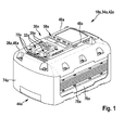
- FIGS. 1 to 4 show a battery 34a of a system with the battery 34a and one in the FIGS. 5 to 7 illustrated battery charger 36b.
- the battery 34a is designed as a tool battery.
- the battery 34a has a rechargeable battery device 10a according to the invention.
- the rechargeable battery device 10a is intended, when used in a humid environment, to protect an electrical area 14a of the rechargeable battery 34a and a tool interface 38a of the rechargeable battery 34a from damage and malfunction by dust, dirt and water.
- the battery 34a has a cell block 40a and a battery outer housing 42a.
- the battery outer housing 42a encloses the cell block 40a.
- the battery outer housing 42a has a main body 44a and a cover housing part 46a.
- the tool interface 38a is disposed on the lid housing part 46a.
- the lid housing part 46a forms an upper side of the battery 34a.
- the lid housing part 46a is formed as a plastic part.
- the tool interface 38a is intended to make a mechanical and an electrical connection with a tool, with a bicycle or with the battery charger 36b.
- the tool interface 38a has guide rails 48a and at least one latching means 50a.
- the guide rails 48a and the locking means 50a are formed by the battery outer housing 42a.
- the tool interface 38a has a first contact 16a, a second contact 18a and a third contact 30a. Between the first contact 16a and the third contact 30a is an operating voltage of the cell block 40a.
- the second contact 18a transmits information between the cell block 40a and the tool, the bicycle or the battery charger 36b in at least one operating state.
- the second contact 18a is disposed between the first contact 16a and the third contact 30a.
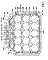
- Cell block 40a includes heat sink 52a, multiple battery cells 54a, cell block housing 56a, electronics 58a, and fasteners 60a.
- the electronics 58a are designed to monitor battery voltages and temperatures of the battery cells 54a and to avoid damaging the battery cells 54a.
- the cell block housing 56a is provided to connect the heat sinks 52a, the battery cells 54a, the electronics 58a, and the fasteners 60a to an assembly that forms the cell block 40a.
- the cell block housing 56a delimits the electrical area 14a, in which the electronics 58a and the battery cells 54a are arranged.
- the contacts 16a, 18a, 30a of the tool interface 38a are partially encapsulated in the cell block housing 56a.
- the cell block housing 56a has air conditioning openings 62a, which are closed by a waterproof, breathable membrane not shown here.
- a sealing device 12a of the rechargeable battery device 10a is provided to seal the electrical area 14a of the cell block 40a which is spanned by the cell block housing 56a.
- the sealing device 12a has a sealing film 64a, a first sealing means 66a and a second sealing means 68a.
- the sealing film 64a is tubular. Alternatively, a sealing film could be bag-shaped.
- the sealing film 64a is formedsschrumpfend.
- the sealing film 64a abuts the cell block 40a at a front side, at a rear side, and at both lateral sides.
- the sealing film 64a covers these sides at least substantially completely.
- the first sealant 66a is formed as a sealant.
- the first sealant 66a is formed as a butyl sealant.
- the first sealing means 66a is provided to seal a gap between the cell block housing 56a and the sealing film 64a.
- the first sealant 66a prevents intrusion of dust and / or moisture into the cell block 40a.
- the second sealing means 68a seals off an underside of the cell block 40a facing away from the tool interface 38a.
- the second sealant 68a is formed as a self-adhesive film.
- the second sealing means 68a closes an opening of the tubular sealing film 64a facing away from the tool interface 38a.
- the sealing device 12 encloses the cell block 40 on five sides.
- the sixth side is sealed by the cell block housing 56a.
- the battery device 10a has a plurality of water film separating means 20a, 22a, 24a.
- the water-film separating means 20a, 22a, 24a are provided to prevent formation of a direct water film between the first contact 16a, the second contact 18a and / or the third contact 30a in at least one operating state.
- the water-film separating means 20a, 22a, 24a are each operatively disposed between the first contact 16a and the second contact 18a or between the second contact 18a and the third contact 30a.
- the first contact 16a and the third contact 30a are formed as contact tulips.
- the second contact 16a has two separately formed contact springs, which are deflected outwards.
- Two of the water film separating means 20a are formed by a housing part 26a which is formed as the lid housing part 46a of the battery outer housing 42a. These two water film separating means 20a are formed as water drainage slits 32a bounded by the housing part 26a. Water can escape from a region of the contacts 16a, 18a, 30a through the water drain slits 32a when the battery 34a with the cover housing part 46a is arranged downwards in the battery charger 36b.
- the water drainage slots 32a are spatially arranged between contact slots 70a through which contacts 16b, 18b, 30b of the battery charger 36b contact the contacts 16a, 18a, 30a of the battery 34a.
- the water drainage slots 32a are aligned parallel to the contact slots 70a.
- the water drainage slots 32a have a main extension, which is aligned parallel to a coupling direction 72a of the tool interface 38a.
- the water drainage slots 32a have a width, in particular perpendicular to the main extension, which is greater than a droplet size of the particular running one Water film, which is given by a surface tension of the water and a material of the water film separating means 20a.
- Two more of the water film separating means 22a are also formed by the housing part 26a, which is formed as the lid housing part 46a of the battery outer housing 42a.
- the two water-film separating means 22a are formed as partitions formed by the housing part 26a.
- One of these water film separating means 22a is disposed between the first contact 16a and the second contact 18a, and another of these water film separating means 22a is disposed between the second contact 18a and the third contact 30a.
- the water-film separating means 22a have a main extension, which is aligned parallel to the coupling direction 72a of the tool interface 38a.
- the water-film separating means 22a extend on a plane perpendicular to a straight line connecting the contacts 16a, 18a, 30a in a shortest path.
- Two of the water film separating means 24a are formed by a housing part 28a of the cell block housing 56a.
- the water-film separating means 24a itself are formed as partitions.
- the water-film separating means 24a have a main extension parallel to a main extension of the contacts 16a, 18a, 30a, which corresponds to more than 50% of the main extension of one of the contacts 16a, 18a, 30a.
- the water-film separating means 24a are provided to fix at least one of the contacts 16a, 18a, 30a, here the second contact 18a.
- the water film separating means 24a are arranged at a distance from the second contact 18a so that the second contact 18b can spring out.
- the lid housing part 46a and the cell block housing 56a and thus the water film separating means 20a, 22a, 24a are made of a hydrophobic material.
- the main body 44a of the battery outer housing 42a has a bottom element 74a and two heat radiation means 76a.
- the bottom element 74a bounds the battery 34a on a lower side, on a front side and on a rear side, in each case based on a coupling direction 72a of the tool interface 38a.
- the bottom element 74a forms four corners adjacent to the underside.
- the bottom member 74a is formed as a plastic part.
- the two heat-radiating means 76a bound the battery 34a on a lateral side, respectively.
- the heat-radiating means 76a are formed as aluminum bodies.
- the heat radiation 76a have cooling fins on an outer side.
- the heat-radiating means 76a, the base body 44a and the lid housing part 46a are screwed together. Together, the heat radiating means 76a, the base body 44a, and the lid housing part 46a completely enclose the cell block 40a.
- a battery could have one or more heat-radiating means, for example at the front, at the back and / or at the bottom.
- the heat sink 52a is designed to dissipate heat from the cell block 40a during a charging and discharging operation.
- the heat sink 52a extends along a straight line through the entire cell block 40a.
- the battery cells 54a are arranged on two opposite sides of the heat sink 52a.
- the heat dissipation means 52a define partially cylindrical recesses which are provided to at least partially receive the rechargeable battery cells 54a.
- one of the attachment means 60a is arranged in each case.
- the attachment means 60a prevent direct contact between the heat sink 52a and the battery cells 54a.
- the fastening means 60a are designed as electrically insulating and in particular partially elastic layer elements.
- the fastening means 60a consist of a material which appears appropriate to a person skilled in the art and has good thermal conductivity.
- the heat sink 52a and the heat radiating means 76a are formed as components formed separately from each other.
- the heat sink 52a and the heat radiating means 76a are connected to each other by screws 78a.
- the screws 78a press one of the heat sink 52a and one of the heat radiating means 76a from two different sides against the sealing film 64a.
- the screws 78a cause a pressing force on the sealing film 64a.
- the heat-dissipating means 52a and the heat-radiating means 76a abut against the sealing film 64a in a planar manner.
- Heat generated during charging and discharging in the battery cells 54a conducts the fixing means 60a to the heat dissipating means 52a.
- the heat sink 52a conducts this heat out of the cell block 40a to the sealing film 64a.
- the sealing film 64a conducts a substantial portion of the heat to the heat radiation means 76a. Another portion of the heat conducts the screws 78a to the heat radiation means 76a.
- the heat radiating means 76a releases the heat to a vicinity of the battery 34a by blasting and convection.
- FIGS. 5 to 7 a further embodiment of the invention is shown.
- the following descriptions and the drawings are essentially limited to the differences between the exemplary embodiments, wherein with respect to identically named components, in particular with regard to components having the same reference numerals, in principle also to the drawing and / or the description of the other embodiments, in particular FIGS. 1 to 4 , can be referenced.
- To distinguish the embodiments of the letter a is the reference numerals of the embodiment in the FIGS. 1 to 4 readjusted.
- the letter a is replaced by the letter b.
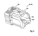
- FIGS. 5 to 7 show the battery charger 36b of a system with in the FIGS. 1 to 4 illustrated battery 34a and the battery charger 36b.
- the battery charger 36b is formed as a tool battery charger.
- the battery charger 36b has a battery device 10b, an electronics housing 80b, a battery housing 82b, an electronics 84b and a cooling device 86b.
- the battery device 10b is designed as a tool battery device.
- the battery device 10b comprises a sealing device 12b, a battery interface 88b, a plurality of water film separating means 20b and a housing part 26b.
- the electronics housing 80b is formed as a metal housing.
- the electronics housing 80b has cooling ribs on at least one outer side.
- the sealing device 12b is provided to at least dust-tight and / or watertight to close an electrical area 14b, spanned by the electronics housing 80b, in which the electronics 84b is arranged.
- the sealing device 12b comprises a sealing means 90b, which seals a gap between a cover element 92b of the electronics housing 80b and a base body 94b of the electronics housing 80b.
- the sealing device 12b comprises two cable seals 96b, 98b.
- a first of the cable seals 96b is provided to seal a supply cable 100b of the battery charger 36b, to which a mains and / or an on-board voltage is applied, in a recess of the electronics housing 80b.
- a second of the cable seals 98b is provided to seal a non-illustrated cable of the battery charger 36b, which contacts the cooling device 86b and battery interface 88b.
- the battery interface 88b is intended to be in the FIGS. 1 to 4 battery 34a to be contacted mechanically and electrically.
- the battery interface 88b points the first contact 16b, the second contact 18b, and the third contact 30b.
- the first contact 16b and the third contact 30b are provided to jointly transmit a charging energy to the battery 34a.
- the second contact 18b in particular together with the first contact 16b and / or the third contact 30b, is intended to transmit information between the battery 34a and the electronics 84b.
- the contacts 16b, 18b, 30b are of the in FIG. 7 Attached housing part 26b of the battery device 10b fixed.
- the housing part 26b is connected to the battery receiving housing 82b.
- the housing part 26b and the battery housing housing 82b may be integrally formed.
- the housing part 26b forms the two water film separating means 20b.
- the water film separating means 20b each delimit a water drainage slit 32b. Water can flow out of a region between the contacts 16b, 18b, 30b into the battery receiving housing 82b through the water drainage slots 32b.
- the water film separating means 20b have a main extension parallel to a main extension of the contacts 16b, 18b, 30b, which is larger than the main extension of the contacts 16b, 18b, 30b.
- the water film separating means 20b extend in two directions parallel to the main extension of the contacts 16b, 18b, 30b via the contacts 16b, 18b, 30b.
- the housing part 26b has webs 102b which, in a region spaced from the contacts 16b, 18b, 30b, bridge the water drainage slots 32b and thus stabilize them mechanically.
- the water drainage slots 32b extend into a region which intersects a main extension plane of one of the contacts 16b, 18b, 30b.
- the contacts 16b, 18b, 30b are arranged on two surfaces 104b, 106b, which are aligned perpendicular to each other.
- the water drainage slots 32b abut both surfaces 104b, 106b.
- the water drainage slots 32b interrupt at least one of the two surfaces 104b, 106b, but preferably both surfaces 104b, 106b, between the contacts 16b, 18b, 30b.
- one water film separating means in particular a water discharge slot, could be arranged on each of the two surfaces 104b, 106b.
- One of the water film separating means 20b is operatively and in particular spatially arranged between the first contact 16b and the second contact 18b.
- One of the water film separating means 20b is effective and in particular spatially between the second contact 18b and the third contact 30b.
- the water film separating means 20b prevent, in at least one operating state, formation of a direct water film between the first contact 16b and the second contact 18b and / or the second contact 18b and the third contact 30b.
- the battery accommodating housing 82b has openings on a lower side, not shown, through which the expired by the water drainage slots 32b water and / or dirt from the battery housing housing 82b can emerge.
- Components of the electronics 84 which generate a high waste heat during operation, are thermally connected to the cover element 92b of the electronics housing 80b.
- the cover element 92b and the base body 94b of the electronics housing 80b are thermally decoupled in part by the sealing means 90b.
- the cover element 92b has a higher temperature during operation than the base body 94b.
- the main body 94b has outer sides that can be touched by an operator.
- the lid member 92b is covered by the battery accommodating case 82b.
- the battery housing 82b is formed as a plastic housing.
- the battery receiving housing 82b encloses a battery receiving area 108b, in which the battery 34a is arranged during a charging process, on at least one level completely.
- the battery accommodating housing 82b encloses the battery receiving area 108b in a tunnel shape.
- the cooling device 86b has a fan 110b which, during a charging process, moves an air flow 112b through the battery receiving housing 82b and thereby cools the battery 34a.
- the fan 110b moves the air flow 112b past the lid member 92b for cooling the lid member 92b.
- the cover element 92b has at least in one area cooling fins, at which the air flow 112b passes.
- a distance 114a of the two water-film separating means 20a of the battery 34a and a distance 114b of the two water-film separating means 20b of the battery charger 36b, each of which has the water discharge slots 32a; Limit 32b, each perpendicular to the coupling direction 72a, are in at least a portion of the water drainage slots 32a; 32b same.
- water that is in the battery outer casing 42a can drain through the water drainage slots 32a of the battery 34a and the water drainage slots 32b of the battery charger 36b.
Landscapes
- Chemical & Material Sciences (AREA)
- Chemical Kinetics & Catalysis (AREA)
- Electrochemistry (AREA)
- General Chemical & Material Sciences (AREA)
- Engineering & Computer Science (AREA)
- Power Engineering (AREA)
- Battery Mounting, Suspending (AREA)
- Secondary Cells (AREA)
- Sealing Battery Cases Or Jackets (AREA)
Abstract
Description
- Es ist bereits eine Akkuvorrichtung, insbesondere eine Werkzeugakkuvorrichtung, mit einer Dichtvorrichtung, die dazu vorgesehen ist, zumindest einen Elektrikbereich wenigstens staubdicht und/oder wasserdicht zu verschließen, mit einem ersten elektrischen Kontakt und zumindest einem zweiten elektrischen Kontakt, die dazu vorgesehen sind, eine elektrische Betriebsenergie und/oder Informationen zu übertragen, vorgeschlagen worden.
- Die Erfindung geht aus von einer Akkuvorrichtung, insbesondere Werkzeugakkuvorrichtung, mit einer Dichtvorrichtung, die dazu vorgesehen ist, zumindest einen Elektrikbereich wenigstens staubdicht und/oder wasserdicht zu verschließen, mit einem ersten elektrischen Kontakt und zumindest einem zweiten elektrischen Kontakt, die dazu vorgesehen sind, eine elektrische Betriebsenergie und/oder Informationen zu übertragen.
- Es wird vorgeschlagen, dass die Akkuvorrichtung zumindest ein Wasserfilmtrennmittel aufweist, das dazu vorgesehen ist, eine Bildung eines direkten Wasserfilms zwischen dem ersten Kontakt und dem zweiten Kontakt insbesondere bei einem Eindringen von Wasser in zumindest einem Betriebszustand zu verhindern. Unter einer "Dichtvorrichtung" soll insbesondere eine, dem Fachmann als sinnvoll erscheinende Vorrichtung verstanden werden, die dazu geeignet ist, ein Eindringen von Staub und/oder Feuchtigkeit in den Zellblock zu verhindern. Insbesondere verhindert die Dichtvorrichtung ein Eindringen von Staub und/oder Feuchtigkeit in einen insbesondere im Wesentlichen gesamten Bereich zwischen den Akkuzellen des Zellblocks. Insbesondere soll unter einer "Dichtvorrichtung" keine Vorrichtung verstanden werden, die eine einzelne Akkuzelle abdichtet oder elektrisch isoliert. Unter "vorgesehen" soll insbesondere speziell programmiert, ausgelegt und/oder ausgestattet verstanden werden. Darunter, dass ein Objekt zu einer bestimmten Funktion vorgesehen ist, soll insbesondere verstanden werden, dass das Objekt diese bestimmte Funktion in zumindest einem Anwendungs- und/oder Betriebszustand erfüllt und/oder ausführt. Insbesondere soll unter einem "Elektrikbereich" ein Bereich verstanden werden, in dem eine Elektrik und/oder eine Elektronik zumindest teilweise angeordnet ist. Vorzugsweise ist eine Elektrik bis auf die Kontakte, insbesondere eine Elektronik, zumindest im Wesentlichen vollständig in dem Elektrikbereich angeordnet. Vorzugsweise sind lediglich die elektrischen Kontakte außerhalb des Elektrikbereichs angeordnet. Vorzugsweise umfasst die Elektrik Akkuzellen, elektrische Verbindungsmittel und eine Elektronik des Akkus. Vorzugsweise sind in dem Elektrikbereich zumindest ein Zellblock und vorteilhaft die Elektronik angeordnet. Unter einem "Zellblock" soll insbesondere eine Einheit mit mehreren Akkuzellen verstanden werden, die dazu vorgesehen sind, eine elektrische Energie insbesondere an ein Werkzeug abzugeben. Vorzugsweise umfasst der Zellblock zumindest zwei Akkuzellen, vorteilhaft zumindest acht Akkuzellen, besonders vorteilhaft zumindest 16 Akkuzellen. Vorteilhaft sind die Akkuzellen relativ zueinander ortsfest angeordnet. Besonders vorteilhaft ordnet ein Wärmeableitmittel des Zellblocks die Akkuzellen relativ zueinander an. Insbesondere weist der Zellblock ein Zellblockgehäuse auf, das dazu vorgesehen ist, das Wärmeableitmittel und vorteilhaft damit die Akkuzellen aneinander zu befestigen. Insbesondere bildet der Zellblock zumindest bei einem Montageschritt eine Baugruppe. Bevorzugt ist der Zellblock dazu vorgesehen, eine elektrische Energie mit einer Spannung größer als 12 Volt, besonders vorteilhaft größer als 20 Volt, bereitzustellen. Insbesondere ist der Zellblock dazu vorgesehen, eine elektrische Energie mit einer Spannung kleiner als 50 Volt bereitzustellen. Insbesondere weist der Zellblock, und damit der Akku, eine Speicherkapazität von weniger als 1000 Wattstunden, vorteilhaft weniger als 500 Wattstunden, besonders vorteilhaft weniger als 250 Wattstunden, auf. Insbesondere weist der Zellblock, und damit der Akku, eine Speicherkapazität von mehr als 10 Wattstunden, vorteilhaft mehr als 25 Wattstunden, besonders vorteilhaft mehr als 100 Wattstunden, auf. Unter einer "Elektronik" soll insbesondere eine Vorrichtung verstanden werden, die zumindest einen elektrischen Strom in einem Gas, in einem Leiter, in einem Vakuum und/oder vorteilhaft in einem Halbleiter beeinflusst. Vorzugsweise weist die Elektronik zumindest einen Transistor, besonders bevorzugt zumindest einen Mikroprozessor auf. Insbesondere soll unter der Wendung "vor einem Eindringen von Staub und/oder Feuchtigkeit schützen" verstanden werden, dass die Dichtvorrichtung in zumindest einem Betriebszustand ein Eindringen von Wasser und/oder Staub in den Zellblock verhindert. Vorzugsweise schützt die Dichtvorrichtung den Zellblock gemäß der Norm IEC 60529 zumindest mit der Schutzklasse IP55, vorzugsweise IP67, besonders bevorzugt IP68. Vorzugsweise sind elektrische Kontakte des Akkus, insbesondere Energiekontakte und Kommunikationskontakte des Akkus, in einem Bereich angeordnet, der außerhalb eines von der Dichtvorrichtung geschützten Bereichs liegt. Unter einem "Kontakt" soll insbesondere ein elektrisch leitfähiges Mittel verstanden werden, das dazu vorgesehen ist, eine Energie und/oder eine Information auf ein mit der Werkzeugschnittstelle des Akkus verbundenes Werkzeug zu übertragen. Vorzugsweise weist der Kontakt eine Kontakttulpe oder einen Kontaktstift auf. Insbesondere soll unter einer "elektrischen Betriebsenergie" eine elektrische Energie verstanden werden, die zur Ausführung einer vorgesehenen Hauptfunktion des Werkzeugs vorgesehen ist. Insbesondere soll unter einem "Wasserfilmtrennmittel" ein Mittel verstanden werden, das dazu vorgesehen ist, eine Funktionsstörung durch Wasser zwischen den elektrischen Kontakten zu vermeiden. Vorzugsweise unterbricht das Wasserfilmtrennmittel in zumindest einem Betriebszustand einen direkten Wasserfilm zwischen den elektrischen Kontakten. Alternativ oder zusätzlich ist das Wasserfilmtrennmittel dazu vorgesehen, eine Verbindung zwischen zwei Wasserfilmen zu verhindern, die jeweils einen der Kontakte berühren. Insbesondere trennt das Wasserfilmtrennmittel den Wasserfilm, zumindest wenn ein Bereich zwischen den Kontakten nach einer vollständigen Flutung mit Wasser entleert wird. Vorzugsweise weist die Akkuvorrichtung mehrere Wasserfilmtrennmittel, besonders bevorzugt zwei Wasserfilmtrennmittel, auf. Alternativ könnte die Akkuvorrichtung genau ein Wasserfilmtrennmittel aufweisen. Unter einem "direkten Wasserfilm" soll insbesondere eine an einer Oberfläche haftende Wasserschicht verstanden werden, die den ersten Kontakt und den zweiten Kontakt auf einem Weg verbindet, der im Wesentlichen einem kürzesten Abstand zwischen den Kontakten außerhalb des Elektrikbereichs entspricht. Unter "im Wesentlichen" soll in diesem Zusammenhang verstanden werden, dass das Wasserfilmtrennmittel einen Wasserfilm in zumindest einem Betriebszustand verhindert, dessen Weg zwischen den Kontakten kürzer ist als zweimal der kürzeste Abstand der Kontakte, vorteilhaft kürzer als eineinhalbmal der kürzeste Abstand der Kontakte. Durch die erfindungsgemäße Ausgestaltung der Akkuvorrichtung kann ein Fehlstrom zwischen den Kontakten vorteilhaft so weit reduziert werden, dass eine Fehlfunktion und Korrosion durch Elektrolyse vermieden werden.
- In einer weiteren Ausgestaltung wird vorgeschlagen, dass die Akkuvorrichtung ein Gehäuseteil aufweist, das die Wasserfilmtrennmittel zumindest teilweise bildet, wodurch eine kostengünstige Fertigung erreicht werden kann. Unter einem "Gehäuseteil" soll insbesondere ein Bauteil eines Außengehäuses der Akkuvorrichtung verstanden werden. Vorzugsweise bildet ein Gehäuseteil eines Zellblockgehäuses des Zellblocks der Akkuvorrichtung das Wasserfilmtrennmittel. Alternativ oder zusätzlich könnte ein Gehäuseteil eines Akkuaußengehäuses der Akkuvorrichtung, insbesondere ein Deckelteil des Akkuaußengehäuses, das Wasserfilmtrennmittel bilden. Des Weiteren könnte das Wasserfilmtrennmittel als ein eigenständiges Bauteil ausgebildet sein. Insbesondere soll unter dem Begriff "bilden" in diesem Zusammenhang verstanden werden, dass das Gehäuseteil eine Form aufweist, die in zumindest einem Betriebszustand einen direkten Wasserfilm zwischen dem ersten Kontakt und dem zweiten Kontakt in zumindest einem Betriebszustand verhindert.
- Des Weiteren wird vorgeschlagen, dass das Wasserfilmtrennmittel zumindest teilweise von einem hydrophoben Material gebildet ist, wodurch der Wasserfilm besonders effektiv getrennt werden kann. Unter einem "hydrophoben Material" soll insbesondere ein Material verstanden werden, das einen Kontaktwinkel mit Wasser größer als 60 Grad vorteilhaft größer als 90 Grad, aufweist. Vorzugsweise bildet das hydrophobe Material zumindest eine Oberfläche des Wasserfilmtrennmittels. Besonders vorteilhaft ist das das Wasserfilmtrennmittel bildende Mittel vollständig aus einem hydrophoben Material gebildet. Alternativ oder zusätzlich könnte das das Wasserfilmtrennmittel bildende Mittel zumindest teilweise mit einem hydrophoben Material, beispielsweise Teflon, beschichtet sein.
- Ferner wird vorgeschlagen, dass das Wasserfilmtrennmittel zwischen dem ersten Kontakt, der bei einem Betrieb die elektrische Betriebsenergie überträgt, und dem zweiten Kontakt, der in zumindest einem Betriebszustand Informationen insbesondere an ein Werkzeug und/oder ein Akkuladegerät überträgt, angeordnet ist, wodurch ein Einfluss einer Betriebsspannung der Betriebsenergie auf ein Signal, das die Informationen an das Werkzeug überträgt, vorteilhaft reduziert werden kann. Insbesondere soll unter dem Begriff "zwischen" in diesem Zusammenhang verstanden werden, dass zumindest ein Wirkungsbereich des Wasserfilmtrennmittels und vorteilhaft das Wasserfilmtrennmittel selbst auf zumindest einer Geraden liegt, die von dem Wasserfilmtrennmittel ausgehend auf einer ersten Seite den ersten Kontakt und auf einer zweiten, anderen Seite den zweiten Kontakt schneidet.
- Zudem wird vorgeschlagen, dass die Akkuvorrichtung zumindest einen dritten Kontakt aufweist, der bei einem Betrieb die elektrische Betriebsenergie überträgt, wodurch eine konstruktiv einfache Informationsübertragung erreicht werden kann.
- Weiterhin wird vorgeschlagen, dass der zweite Kontakt zwischen dem ersten Kontakt und dem dritten Kontakt angeordnet ist, wodurch zwischen dem ersten Kontakt und dem dritten Kontakt konstruktiv einfach ein großer Abstand möglich ist, was zu einem geringen Fehlstrom zwischen den Kontakten durch den Wasserfilm führt. Vorzugsweise weist die Akkuvorrichtung zwei Wasserfilmtrennmittel auf, von denen immer eines zwischen zwei der Kontakte angeordnet ist.
- In einer vorteilhaften Ausbildung der Erfindung wird vorgeschlagen, dass das Wasserfilmtrennmittel zumindest einen Wasserablaufschlitz begrenzt, wodurch ein im Gegensatz zu einer Konstruktion mit Trennwänden geringer Platzbedarf erreicht werden kann. Unter einem "Wasserablaufschlitz" soll insbesondere ein Schlitz verstanden werden, der dazu vorgesehen ist, Wasser aus Bereichen zwischen den Kontakten in Richtung einer Schwerkraft abzuführen. Insbesondere führen die Wasserablaufschlitze das Wasser in ein Gehäuse der Akkuvorrichtung hinein. Vorzugsweise weist die Akkuvorrichtung mehrere Wasserfilmtrennmittel auf, die mehrere Wasserablaufschlitze begrenzen. Vorzugsweise weist der Wasserablaufschlitz entlang einer Ablaufrichtung eine gleichbleibende Breite auf. Alternativ könnte der Wasserablaufschlitz entlang der Ablaufrichtung unterschiedliche Breiten aufweisen. Des Weiteren könnte das Wasserfilmtrennmittel eine Blende aufweisen, die auf einer den Kontakten abgewandten Seite des Gehäuseteils angeordnet ist und zumindest teilweise in der Ablaufrichtung des Wasserablaufschlitzes angeordnet ist. Durch die Blende kann bei einem Betrachter ein vorteilhaft geschlossener Eindruck erreicht werden und ein Eindringen von größeren Objekten in einem von dem Gehäuseteil begrenzten Bereich verhindert werden
- Des Weiteren wird vorgeschlagen, dass das Wasserfilmtrennmittel eine Trennwand bildet, wodurch eine Fehlfunktion durch einen Fehlstrom auch bei viel Wasser zwischen den Kontakten, insbesondere bei auch bei einem vollständig gefluteten Bereich, erreicht werden kann. Insbesondere soll unter einer "Trennwand" ein Mittel verstanden werden, das einen Raum, in dem der erste Kontakt angeordnet ist, und einen Raum, in dem der zweite Kontakt angeordnet ist, voneinander trennt. Vorzugsweise weist die Akkuvorrichtung mehrere Wasserfilmtrennmittel auf, die mehrere Trennwände bilden. Ferner wird ein Akku, insbesondere Werkzeugakku, mit einer erfindungsgemäßen Akkuvorrichtung vorgeschlagen. Insbesondere soll unter einem "Werkzeugakku" ein Akku verstanden werden, der dazu vorgesehen ist, ein Werkzeug mit elektrischer Energie zu versorgen. Insbesondere soll unter einem "Werkzeug" ein, dem Fachmann als sinnvoll erscheinendes Werkzeug, vorteilhaft jedoch eine Bohrmaschine, ein Bohrhammer, ein Schlaghammer, eine Säge, ein Hobel, ein Schrauber, eine Fräse, ein Schleifer, ein Winkelschleifer, ein Baustellenmessgerät, ein Multifunktionswerkzeug und/oder vorteilhaft ein Gartengerät, insbesondere ein Rasenmäher, verstanden werden. Alternativ oder zusätzlich könnte der Akku dazu vorgesehen sein, ein zumindest teilweise elektrisch angetriebenes Fahrrad mit elektrischer Energie zu versorgen. Insbesondere ist der Akku von einem Bediener zur Versorgung eines Geräts zerstörungsfrei und insbesondere werkzeuglos mit dem Gerät verbindbar und von dem Gerät trennbar.
- Zudem wird ein Akkuladegerät, insbesondere ein Werkzeugakkuladegerät, mit einer erfindungsgemäßen Akkuvorrichtung vorgeschlagen. Unter einem "Akkuladegerät" soll insbesondere ein Gerät verstanden werden, das dazu vorgesehen ist, eine Versorgungsspannung, insbesondere eine Bordspannung und/oder eine Netzspannung, in eine Ladespannung zu wandeln. Vorzugsweise ist das Akkuladegerät dazu vorgesehen, einen Ladevorgang zu steuern und/oder vorteilhaft zu regeln.
- Die erfindungsgemäße Akkuvorrichtung soll hierbei nicht auf die oben beschriebene Anwendung und Ausführungsform beschränkt sein. Insbesondere kann die erfindungsgemäße Akkuvorrichtung zu einer Erfüllung einer hierin beschriebenen Funktionsweise eine von einer hierin genannten Anzahl von einzelnen Elementen, Bauteilen und Einheiten abweichende Anzahl aufweisen.
- Weitere Vorteile ergeben sich aus der folgenden Zeichnungsbeschreibung. In der Zeichnung sind zwei Ausführungsbeispiele der Erfindung dargestellt. Die Zeichnung, die Beschreibung und die Ansprüche enthalten zahlreiche Merkmale in Kombination. Der Fachmann wird die Merkmale zweckmäßigerweise auch einzeln betrachten und zu sinnvollen weiteren Kombinationen zusammenfassen.
- Es zeigen:
- Fig. 1
- einen Akku mit einer erfindungsgemäßen Akkuvorrichtung in einer perspektivischen Darstellung,
- Fig. 2
- einen Schnitt durch eine Werkzeugschnittstelle des Akkus aus
Figur 1 , - Fig. 3
- einen Zellblock, Kontakte und eine Dichtvorrichtung des Akkus aus
Figur 1 in einer perspektivischen Darstellung, - Fig. 4
- eine Schnittdarstellung des Akkus aus
Figur 1 , - Fig. 5
- ein Akkuladegerät mit einer erfindungsgemäßen Akkuvorrichtung in einer perspektivischen Darstellung,
- Fig. 6
- eine Schnittdarstellung des Akkuladegeräts aus
Figur 4 und - Fig. 7
- ein die Wasserfilmtrennmittel aufweisendes Gehäuseteil des Akkuladegeräts aus
Figur 4 in einer perspektivischen Darstellung. -
Figuren 1 bis 4 zeigen einen Akku 34a eines Systems mit dem Akku 34a und einem in denFiguren 5 bis 7 dargestellten Akkuladegerät 36b. Der Akku 34a ist als ein Werkzeugakku ausgebildet. Der Akku 34a weist eine erfindungsgemäße Akkuvorrichtung 10a auf. Die Akkuvorrichtung 10a ist dazu vorgesehen, bei einem Einsatz in einer feuchten Umgebung einen Elektrikbereich 14a des Akkus 34a und eine Werkzeugschnittstelle 38a des Akkus 34a vor eine Beschädigung und einer Fehlfunktion durch Staub, Schmutz und Wasser zu schützen. - Des Weiteren weist der Akku 34a einen Zellblock 40a und ein Akkuaußengehäuse 42a auf. Das Akkuaußengehäuse 42a umschließt den Zellblock 40a. Das Akkuaußengehäuse 42a weist einen Grundkörper 44a und ein Deckelgehäuseteil 46a auf. Die Werkzeugschnittstelle 38a ist an dem Deckelgehäuseteil 46a angeordnet. Das Deckelgehäuseteil 46a bildet eine Oberseite des Akkus 34a. Das Deckelgehäuseteil 46a ist als ein Kunststoffteil ausgebildet.
- Die Werkzeugschnittstelle 38a ist dazu vorgesehen, eine mechanische und eine elektrische Verbindung mit einem Werkzeug, mit einem Fahrrad oder mit dem Akkuladegerät 36b herzustellen. Zur mechanischen Verbindung weist die Werkzeugschnittstelle 38a Führungsschienen 48a und zumindest ein Rastmittel 50a auf. Die Führungsschienen 48a und das Rastmittel 50a werden von dem Akkuaußengehäuse 42a gebildet. Die Werkzeugschnittstelle 38a weist einen ersten Kontakt 16a, einen zweiten Kontakt 18a und einen dritten Kontakt 30a auf. Zwischen dem ersten Kontakt 16a und dem dritten Kontakt 30a liegt eine Betriebsspannung des Zellblocks 40a an. Der zweite Kontakt 18a überträgt in zumindest einem Betriebszustand Informationen zwischen dem Zellblock 40a und dem Werkzeug, dem Fahrrad oder dem Akkuladegerät 36b. Der zweite Kontakt 18a ist zwischen dem ersten Kontakt 16a und dem dritten Kontakt 30a angeordnet.
- Der Zellblock 40a weist Wärmeableitmittel 52a, mehrere Akkuzellen 54a, ein Zellblockgehäuse 56a, eine Elektronik 58a und Befestigungsmittel 60a auf. Die Elektronik 58a ist dazu vorgesehen, Akkuspannungen und Temperaturen der Akkuzellen 54a zu überwachen und eine Beschädigung der Akkuzellen 54a zu vermeiden. Das Zellblockgehäuse 56a ist dazu vorgesehen, die Wärmeableitmittel 52a, die Akkuzellen 54a, die Elektronik 58a und die Befestigungsmittel 60a zu einer Baugruppe zu verbinden, die den Zellblock 40a bildet.
- Das Zellblockgehäuse 56a begrenzt den Elektrikbereich 14a, in dem die Elektronik 58a und die Akkuzellen 54a angeordnet sind. Die Kontakte 16a, 18a, 30a der Werkzeugschnittstelle 38a sind teilweise in das Zellblockgehäuse 56a eingegossen. Das Zellblockgehäuse 56a weist Klimatisierungsöffnungen 62a auf, die mit einer hier nicht näher dargestellten wasserdichten, atmungsaktiven Membran verschlossen sind.
- Eine Dichtvorrichtung 12a der Akkuvorrichtung 10a ist dazu vorgesehen, den von dem Zellblockgehäuse 56a aufgespannten Elektrikbereich 14a des Zellblocks 40a abzudichten. Die Dichtvorrichtung 12a weist eine Dichtfolie 64a, ein erstes Dichtmittel 66a und ein zweites Dichtmittel 68a auf. Die Dichtfolie 64a ist schlauchförmig ausgebildet. Alternativ könnte eine Dichtfolie sackförmig ausgebildet sein. Die Dichtfolie 64a ist selbstschrumpfend ausgebildet. Die Dichtfolie 64a liegt an einer Vorderseite, an einer Hinterseite und an beiden Lateralseiten an dem Zellblock 40a an. Die Dichtfolie 64a deckt diese Seiten zumindest im Wesentlichen vollständig ab.
- Das erste Dichtmittel 66a ist als eine Dichtmasse ausgebildet. Hier ist das erste Dichtmittel 66a als ein Butyldichtstoff ausgebildet. Das erste Dichtmittel 66a ist dazu vorgesehen, einen Spalt zwischen dem Zellblockgehäuse 56a und der Dichtfolie 64a abzudichten. Somit verhindert das erste Dichtmittel 66a ein Eindringen von Staub und/oder Feuchtigkeit in den Zellblock 40a.
- Das zweite Dichtmittel 68a dichtet eine der Werkzeugschnittstelle 38a abgewandte Unterseite des Zellblocks 40a ab. Das zweite Dichtmittel 68a ist als eine selbstklebende Folie ausgebildet. Das zweite Dichtmittel 68a verschließt eine der Werkzeugschnittstelle 38a abgewandte Öffnung der schlauchförmigen Dichtfolie 64a. Somit umschließt die Dichtvorrichtung 12 den Zellblock 40 auf fünf Seiten. Die sechste Seite wird von dem Zellblockgehäuse 56a abgedichtet.
- Die Akkuvorrichtung 10a weist mehrere Wasserfilmtrennmittel 20a, 22a, 24a auf. Die Wasserfilmtrennmittel 20a, 22a, 24a sind dazu vorgesehen, eine Bildung eines direkten Wasserfilms zwischen dem ersten Kontakt 16a, dem zweiten Kontakt 18a und/oder dem dritten Kontakt 30a in zumindest einem Betriebszustand zu verhindern. Die Wasserfilmtrennmittel 20a, 22a, 24a sind jeweils wirkungsmäßig zwischen dem ersten Kontakt 16a und dem zweiten Kontakt 18a oder zwischen dem zweiten Kontakt 18a und dem dritten Kontakt 30a angeordnet. Der erste Kontakt 16a und der dritte Kontakt 30a sind als Kontakttulpen ausgebildet. Der zweite Kontakt 16a weist zwei getrennt ausgebildete Kontaktfedern aus, die nach außen auslenkbar sind.
- Zwei der Wasserfilmtrennmittel 20a sind von einem Gehäuseteil 26a gebildet, das als das Deckelgehäuseteil 46a des Akkuaußengehäuses 42a ausgebildet ist. Diese zwei Wasserfilmtrennmittel 20a sind als von dem Gehäuseteil 26a begrenzte Wasserablaufschlitze 32a ausgebildet. Durch die Wasserablaufschlitze 32a kann Wasser aus einem Bereich der Kontakte 16a, 18a, 30a austreten, wenn der Akku 34a mit dem Deckelgehäuseteil 46a nach unten in dem Akkuladegerät 36b angeordnet ist. Die Wasserablaufschlitze 32a sind räumlich zwischen Kontaktschlitzen 70a angeordnet, durch die Kontakte 16b, 18b, 30b des Akkuladegeräts 36b die Kontakte 16a, 18a, 30a des Akkus 34a kontaktieren. Die Wasserablaufschlitze 32a sind parallel zu den Kontaktschlitzen 70a ausgerichtet. Die Wasserablaufschlitze 32a weisen eine Haupterstreckung auf, die parallel zu einer Koppelrichtung 72a der Werkzeugschnittstelle 38a ausgerichtet ist.
- Die Wasserablaufschlitze 32a weisen eine Breite insbesondere senkrecht zu der Haupterstreckung auf, die größer ist als eine Tröpfchengröße des insbesondere ablaufenden Wasserfilms, die durch eine Oberflächenspannung des Wassers und ein Material des Wasserfilmtrennmittels 20a gegeben ist.
- Zwei weitere der Wasserfilmtrennmittel 22a sind ebenfalls von dem Gehäuseteil 26a gebildet, das als das Deckelgehäuseteil 46a des Akkuaußengehäuse 42a ausgebildet ist. Die zwei Wasserfilmtrennmittel 22a sind als von dem Gehäuseteil 26a gebildete Trennwände ausgebildet. Eines dieser Wasserfilmtrennmittel 22a ist zwischen dem ersten Kontakt 16a und dem zweiten Kontakt 18a und ein weiteres dieser Wasserfilmtrennmittel 22a ist zwischen dem zweiten Kontakt 18a und dem dritten Kontakt 30a angeordnet. Die Wasserfilmtrennmittel 22a weisen eine Haupterstreckung auf, die parallel zu der Koppelrichtung 72a der Werkzeugschnittstelle 38a ausgerichtet ist. Die Wasserfilmtrennmittel 22a erstrecken sich auf einer Ebene, die senkrecht zu einer Geraden ausgerichtet ist, die die Kontakte 16a, 18a, 30a auf einem kürzesten Weg verbindet.
- Zwei der Wasserfilmtrennmittel 24a sind von einem Gehäuseteil 28a des Zellblockgehäuses 56a gebildet. Die Wasserfilmtrennmittel 24a selbst sind als Trennwände ausgebildet. Die Wasserfilmtrennmittel 24a weisen eine Haupterstreckung parallel zu einer Haupterstreckung der Kontakte 16a, 18a, 30a auf, die mehr als 50 % der Haupterstreckung eines der Kontakte 16a, 18a, 30a entspricht. Die Wasserfilmtrennmittel 24a sind dazu vorgesehen, zumindest einen der Kontakte 16a, 18a, 30a zu befestigen, und zwar hier den zweiten Kontakt 18a. Die Wasserfilmtrennmittel 24a sind in einem Bereich von dem zweiten Kontakt 18a beabstandet angeordnet, damit der zweite Kontakt 18b ausfedern kann. Das Deckelgehäuseteil 46a und das Zellblockgehäuse 56a und somit die Wasserfilmtrennmittel 20a, 22a, 24a sind aus einem hydrophoben Material hergestellt.
- Der Grundkörper 44a des Akkuaußengehäuses 42a weist ein Bodenelement 74a und zwei Wärmeabstrahlmittel 76a auf. Das Bodenelement 74a begrenzt den Akku 34a auf einer Unterseite, auf einer Vorderseite und auf einer Hinterseite, jeweils bezogen auf eine Koppelrichtung 72a der Werkzeugschnittstelle 38a. Zudem bildet das Bodenelement 74a vier an die Unterseite angrenzende Ecken. Das Bodenelement 74a ist als ein Kunststoffteil ausgebildet.
- Die zwei Wärmeabstrahlmittel 76a begrenzen den Akku 34a jeweils auf einer Lateralseite. Die Wärmeabstrahlmittel 76a sind als Aluminiumkörper ausgebildet. Die Wärmeabstrahlmittel 76a weisen an einer Außenseite Kühlrippen auf. Die Wärmeabstrahlmittel 76a, der Grundkörper 44a und das Deckelgehäuseteil 46a sind miteinander verschraubt. Zusammen umschließen die Wärmeabstrahlmittel 76a, der Grundkörper 44a und das Deckelgehäuseteil 46a den Zellblock 40a vollständig. Alternativ oder zusätzlich könnte ein Akku ein oder mehrere Wärmeabstrahlmittel, beispielsweise an der Vorderseite, an der Rückseite und/oder an der Unterseite, aufweisen.
- Die Wärmeableitmittel 52a sind dazu vorgesehen, Wärme bei einem Ladevorgang und einem Entladevorgang aus dem Zellblock 40a abzuleiten. Die Wärmeableitmittel 52a erstrecken sich entlang einer Geraden durch den gesamten Zellblock 40a. Auf zwei einander abgewandten Seiten der Wärmeableitmittel 52a sind die Akkuzellen 54a angeordnet. Die Wärmeableitmittel 52a begrenzen teilzylinderförmige Aussparungen, die dazu vorgesehen sind, die Akkuzellen 54a zumindest teilweise aufzunehmen. Zwischen den Wärmeableitmitteln 52a und den Akkuzellen 54a ist jeweils eines der Befestigungsmittel 60a angeordnet. Die Befestigungsmittel 60a verhindern einen direkten Kontakt zwischen den Wärmeableitmitteln 52a und den Akkuzellen 54a. Die Befestigungsmittel 60a sind als elektrisch isolierende und insbesondere teilelastische Schichtelemente ausgebildet. Die Befestigungsmittel 60a bestehen aus einem, dem Fachmann als sinnvoll erscheinenden Material mit einer guten Wärmeleitfähigkeit.
- Die Wärmeableitmittel 52a und die Wärmeabstrahlmittel 76a sind als voneinander getrennt ausgebildete Bauteile gebildet. Die Wärmeableitmittel 52a und die Wärmeabstrahlmittel 76a sind durch Schrauben 78a miteinander verbunden. Die Schrauben 78a drücken eines der Wärmeableitmittel 52a und eines der Wärmeabstrahlmittel 76a von zwei verschiedenen Seiten gegen die Dichtfolie 64a. Somit bewirken die Schrauben 78a eine Presskraft auf die Dichtfolie 64a. Dadurch liegen die Wärmeableitmittel 52a und die Wärmeabstrahlmittel 76a flächig an der Dichtfolie 64a an.
- Bei einem Laden und einem Entladen in den Akkuzellen 54a entstehende Wärme leiten die Befestigungsmittel 60a zu den Wärmeableitmitteln 52a. Die Wärmeableitmittel 52a leiten diese Wärme aus dem Zellblock 40a heraus zu der Dichtfolie 64a. Die Dichtfolie 64a leitet einen wesentlichen Anteil der Wärme zu den Wärmeabstrahlmitteln 76a. Einen weiteren Anteil der Wärme leiten die Schrauben 78a zu den Wärmeabstrahlmitteln 76a. Die Wärmeabstrahlmittel 76a geben die Wärme durch Abstrahlen und Konvektion an eine Umgebung des Akkus 34a ab.
- In den
Figuren 5 bis 7 ist ein weiteres Ausführungsbeispiel der Erfindung gezeigt. Die nachfolgenden Beschreibungen und die Zeichnung beschränken sich im Wesentlichen auf die Unterschiede zwischen den Ausführungsbeispielen, wobei bezüglich gleich bezeichneter Bauteile, insbesondere in Bezug auf Bauteile mit gleichen Bezugszeichen, grundsätzlich auch auf die Zeichnung und/oder die Beschreibung der anderen Ausführungsbeispiele, insbesondere derFiguren 1 bis 4 , verwiesen werden kann. Zur Unterscheidung der Ausführungsbeispiele ist der Buchstabe a den Bezugszeichen des Ausführungsbeispiels in denFiguren 1 bis 4 nachgestellt. In dem Ausführungsbeispiel derFiguren 5 bis 7 ist der Buchstabe a durch den Buchstaben b ersetzt. - Die
Figuren 5 bis 7 zeigen das Akkuladegerät 36b eines Systems mit dem in denFiguren 1 bis 4 dargestellten Akku 34a und dem Akkuladegerät 36b. Das Akkuladegerät 36b ist als ein Werkzeugakkuladegerät ausgebildet. Das Akkuladegerät 36b weist eine Akkuvorrichtung 10b, ein Elektronikgehäuse 80b, ein Akkuaufnahmegehäuse 82b, eine Elektronik 84b und eine Kühlvorrichtung 86b auf. Die Akkuvorrichtung 10b ist als eine Werkzeugakkuvorrichtung ausgebildet. Die Akkuvorrichtung 10b umfasst eine Dichtvorrichtung 12b, eine Akkuschnittstelle 88b, mehrere Wasserfilmtrennmittel 20b und ein Gehäuseteil 26b. - Das Elektronikgehäuse 80b ist als ein Metallgehäuse ausgebildet. Das Elektronikgehäuse 80b weist zumindest an einer Außenseite Kühlrippen auf. Die Dichtvorrichtung 12b ist dazu vorgesehen, einen von dem Elektronikgehäuse 80b aufgespannten Elektrikbereich 14b, in dem die Elektronik 84b angeordnet ist, wenigstens staubdicht und/oder wasserdicht zu verschließen. Die Dichtvorrichtung 12b umfasst ein Dichtmittel 90b, das einen Spalt zwischen einem Deckelelement 92b des Elektronikgehäuses 80b und einem Grundkörper 94b des Elektronikgehäuses 80b abdichtet.
- Des Weiteren umfasst die Dichtvorrichtung 12b zwei Kabeldichtungen 96b, 98b. Eine erste der Kabeldichtungen 96b ist dazu vorgesehen, ein Versorgungskabel 100b des Akkuladegeräts 36b, an dem eine Netz- und/oder eine Bordspannung anliegt, in einer Aussparung des Elektronikgehäuses 80b abzudichten. Eine zweite der Kabeldichtungen 98b ist dazu vorgesehen, ein nicht näher dargestelltes Kabel des Akkuladegerät 36b abzudichten, das die Kühlvorrichtung 86b und Akkuschnittstelle 88b kontaktiert.
- Die Akkuschnittstelle 88b ist dazu vorgesehen, den in den
Figuren 1 bis 4 dargestellten Akku 34a mechanisch und elektrisch zu kontaktieren. Die Akkuschnittstelle 88b weist den ersten Kontakt 16b, den zweiten Kontakt 18b und den dritten Kontakt 30b auf. Der erste Kontakt 16b und der dritte Kontakt 30b sind dazu vorgesehen, gemeinsam eine Ladeenergie an den Akku 34a zu übertragen. Der zweite Kontakt 18b ist, insbesondere gemeinsam mit dem ersten Kontakt 16b und/oder dem dritten Kontakt 30b, dazu vorgesehen, Informationen zwischen dem Akku 34a und der Elektronik 84b zu übertragen. - Die Kontakte 16b, 18b, 30b werden von dem in
Figur 7 näher dargestellten Gehäuseteil 26b der Akkuvorrichtung 10b befestigt. Das Gehäuseteil 26b ist mit dem Akkuaufnahmegehäuse 82b verbunden. Alternativ könnten das Gehäuseteil 26b und das Akkuaufnahmegehäuse 82b einstückig ausgebildet sein. Das Gehäuseteil 26b bildet die zwei Wasserfilmtrennmittel 20b. Die Wasserfilmtrennmittel 20b begrenzen jeweils einen Wasserablaufschlitz 32b. Durch die Wasserablaufschlitze 32b kann Wasser aus einem Bereich zwischen den Kontakten 16b, 18b, 30b in das Akkuaufnahmegehäuse 82b ablaufen. - Die Wasserfilmtrennmittel 20b weisen eine Haupterstreckung parallel zu einer Haupterstreckung der Kontakte 16b, 18b, 30b auf, die größer ist als die Haupterstreckung der Kontakte 16b, 18b, 30b. Die Wasserfilmtrennmittel 20b erstrecken sich in zwei Richtungen parallel zu der Haupterstreckung der Kontakte 16b, 18b, 30b über die Kontakte 16b, 18b, 30b heraus. Das Gehäuseteil 26b weist Stege 102b auf, die in einem von den Kontakten 16b, 18b, 30b beabstandeten Bereich die Wasserablaufschlitze 32b überbrücken und somit mechanisch stabilisieren.
- Die Wasserablaufschlitze 32b erstrecken sich in einen Bereich, den eine Haupterstreckungsebene eines der Kontakte 16b, 18b, 30b schneidet. Die Kontakte 16b, 18b, 30b sind an zwei Flächen 104b, 106b angeordnet, die senkrecht zueinander ausgerichtet sind. Die Wasserablaufschlitze 32b grenzen an beide Flächen 104b, 106b an. Die Wasserablaufschlitze 32b unterbrechen zumindest eine der beiden Flächen 104b, 106b, vorzugsweise jedoch beide Flächen 104b, 106b, zwischen den Kontakten 16b, 18b, 30b. Alternativ oder zusätzlich könnte an jeder der beiden Flächen 104b, 106b jeweils ein Wasserfilmtrennmittel, insbesondere ein Wasserablaufschlitz, angeordnet sein.
- Eines der Wasserfilmtrennmittel 20b ist wirkungsmäßig und insbesondere räumlich zwischen dem ersten Kontakt 16b und dem zweiten Kontakt 18b angeordnet. Eines der Wasserfilmtrennmittel 20b ist wirkungsmäßig und insbesondere räumlich zwischen dem zweiten Kontakt 18b und dem dritten Kontakt 30b angeordnet. Die Wasserfilmtrennmittel 20b verhindern in zumindest einem Betriebszustand eine Bildung eines direkten Wasserfilms zwischen dem ersten Kontakt 16b und dem zweiten Kontakt 18b und/oder dem zweiten Kontakt 18b und dem dritten Kontakt 30b. Das Akkuaufnahmegehäuse 82b weist an einer Unterseite nicht näher dargestellte Öffnungen auf, durch die das durch die Wasserablaufschlitze 32b abgelaufene Wasser und/oder Schmutz aus dem Akkuaufnahmegehäuse 82b austreten kann.
- Bauteile der Elektronik 84, an denen bei einem Betrieb eine hohe Abwärme entsteht, sind thermisch mit dem Deckelelement 92b des Elektronikgehäuses 80b verbunden. Das Deckelelement 92b und der Grundkörper 94b des Elektronikgehäuses 80b sind thermisch durch das Dichtmittel 90b teilweise entkoppelt. Dadurch weist das Deckelelement 92b bei einem Betrieb eine höhere Temperatur auf als der Grundkörper 94b. Der Grundkörper 94b weist Außenseiten auf, die von einem Bediener berührbar sind. Das Deckelelement 92b ist von dem Akkuaufnahmegehäuse 82b abgedeckt.
- Das Akkuaufnahmegehäuse 82b ist als ein Kunststoffgehäuse ausgebildet. Das Akkuaufnahmegehäuse 82b umschließt einen Akkuaufnahmebereich 108b, in dem der Akku 34a bei einem Ladevorgang angeordnet ist, auf zumindest einer Ebene vollständig. Insbesondere umschließt das Akkuaufnahmegehäuse 82b den Akkuaufnahmebereich 108b tunnelförmig. Die Kühlvorrichtung 86b weist einen Ventilator 110b auf, der bei einem Ladevorgang einen Luftstrom 112b durch das Akkuaufnahmegehäuse 82b bewegt und dadurch den Akku 34a kühlt. Der Ventilator 110b bewegt den Luftstrom 112b an dem Deckelelement 92b zur Kühlung des Deckelelements 92b vorbei. Das Deckelelement 92b weist zumindest in einem Bereich Kühlrippen auf, an denen der Luftstrom 112b vorbeistreicht.
- Ein Abstand 114a der zwei Wasserfilmtrennmittel 20a des Akkus 34a und ein Abstand 114b der zwei Wasserfilmtrennmittel 20b des Akkuladegeräts 36b, die jeweils die Wasserablaufschlitze 32a; 32b begrenzen, jeweils senkrecht zu der Koppelrichtung 72a, sind in zumindest einem Bereich der Wasserablaufschlitze 32a; 32b gleich. Somit kann Wasser, das sich in dem Akkuaußengehäuse 42a befindet, durch die Wasserablaufschlitze 32a des Akkus 34a und die Wasserablaufschlitze 32b des Akkuladegeräts 36b abfließen.
Claims (11)
- Akkuvorrichtung, insbesondere Werkzeugakkuvorrichtung, mit einer Dichtvorrichtung (12a; 12b), die dazu vorgesehen ist, zumindest einen Elektrikbereich (14a; 14b) wenigstens staubdicht und/oder wasserdicht zu verschließen, mit einem ersten elektrischen Kontakt (16a; 16b) und zumindest einem zweiten elektrischen Kontakt (18a; 18b), die dazu vorgesehen sind, eine elektrische Betriebsenergie und/oder Informationen zu übertragen, gekennzeichnet durch zumindest ein Wasserfilmtrennmittel (20a, 22a, 24a; 20b), das dazu vorgesehen ist, eine Bildung eines direkten Wasserfilms zwischen dem ersten Kontakt (16a; 16b) und dem zweiten Kontakt (18a; 18b) in zumindest einem Betriebszustand zu verhindern.
- Akkuvorrichtung nach Anspruch 1, gekennzeichnet durch ein Gehäuseteil (26a, 28a; 26b), das das Wasserfilmtrennmittel (20a, 22a, 24a; 20b) zumindest teilweise bildet.
- Akkuvorrichtung nach Anspruch 1 oder 2, dadurch gekennzeichnet, dass das Wasserfilmtrennmittel (20a, 22a, 24a; 20b) zumindest teilweise von einem hydrophoben Material gebildet ist.
- Akkuvorrichtung nach einem der vorhergehenden Ansprüche, dadurch gekennzeichnet, dass das Wasserfilmtrennmittel (20a, 22a, 24a; 20b) zwischen dem ersten Kontakt (16a; 16b), der bei einem Betrieb die elektrische Betriebsenergie überträgt, und dem zweiten Kontakt (18a; 18b) der in zumindest einem Betriebszustand Informationen überträgt, angeordnet ist.
- Akkuvorrichtung nach Anspruch 4, gekennzeichnet durch zumindest einen dritten Kontakt (30a; 30b), der bei einem Betrieb die elektrische Betriebsenergie überträgt.
- Akkuvorrichtung nach Anspruch 5, dadurch gekennzeichnet, dass der zweite Kontakt (18a; 18b) zwischen dem ersten Kontakt (16a; 16b) und dem dritten Kontakt (30a; 30b) angeordnet ist.
- Akkuvorrichtung nach einem der vorhergehenden Ansprüche, dadurch gekennzeichnet, dass das Wasserfilmtrennmittel (20a; 20b) zumindest einen Wasserablaufschlitz (32a; 32b) begrenzt.
- Akkuvorrichtung nach einem der vorhergehenden Ansprüche, dadurch gekennzeichnet, dass das Wasserfilmtrennmittel (22a, 24a) eine Trennwand bildet.
- Akku, insbesondere Werkzeugakku, mit einer Akkuvorrichtung (10a) nach einem der vorhergehenden Ansprüche.
- Akkuladegerät, insbesondere Werkzeugakkuladegerät, mit einer Akkuvorrichtung (10b) nach einem der Ansprüche 1 bis 8.
- System mit einem Akku (34a) nach Anspruch 9 und einem Akkuladegerät (36b) nach Anspruch 10.
Applications Claiming Priority (1)
| Application Number | Priority Date | Filing Date | Title |
|---|---|---|---|
| DE102013218531.6A DE102013218531B4 (de) | 2013-09-16 | 2013-09-16 | Akkuvorrichtung |
Publications (2)
| Publication Number | Publication Date |
|---|---|
| EP2849260A1 true EP2849260A1 (de) | 2015-03-18 |
| EP2849260B1 EP2849260B1 (de) | 2023-04-26 |
Family
ID=51494142
Family Applications (1)
| Application Number | Title | Priority Date | Filing Date |
|---|---|---|---|
| EP14183877.1A Active EP2849260B1 (de) | 2013-09-16 | 2014-09-08 | Wiederaufladbare Batterie |
Country Status (3)
| Country | Link |
|---|---|
| EP (1) | EP2849260B1 (de) |
| CN (1) | CN104466045B (de) |
| DE (1) | DE102013218531B4 (de) |
Cited By (2)
| Publication number | Priority date | Publication date | Assignee | Title |
|---|---|---|---|---|
| US10950912B2 (en) | 2017-06-14 | 2021-03-16 | Milwaukee Electric Tool Corporation | Arrangements for inhibiting intrusion into battery pack electrical components |
| US12362419B2 (en) | 2021-12-22 | 2025-07-15 | Techtronic Cordless Gp | Circular saw with drain feature |
Families Citing this family (3)
| Publication number | Priority date | Publication date | Assignee | Title |
|---|---|---|---|---|
| MX2020008197A (es) | 2018-02-12 | 2020-09-22 | Techtronic Cordless Gp | Paquete de baterias que contiene conector giratorio. |
| WO2020077618A1 (en) * | 2018-10-19 | 2020-04-23 | Tti (Macao Commercial Offshore) Limited | Battery packs containing configurable terminal holder |
| DE102022210187A1 (de) | 2022-09-27 | 2024-03-28 | Robert Bosch Gesellschaft mit beschränkter Haftung | Akkupack und Zellmodulgehäuse |
Citations (4)
| Publication number | Priority date | Publication date | Assignee | Title |
|---|---|---|---|---|
| EP0994523A1 (de) * | 1998-10-15 | 2000-04-19 | Makita Corporation | Batteriesatz mit verbesserter Wärmeabstrahlung und Dichtung |
| EP1035599A1 (de) * | 1999-03-12 | 2000-09-13 | Toshiba Battery Co., Ltd. | Batteriesatz und Kraftbetriebenes Werkzeug |
| EP1100173A2 (de) * | 1999-11-10 | 2001-05-16 | Makita Corporation | Batterieladevorrichtung |
| EP2487736A1 (de) * | 2011-02-14 | 2012-08-15 | Makita Corporation | Batterien für Elektrowerkzeuge und Verfahren zum Montieren von Batterieendgeräten für Batteriegehäuse |
Family Cites Families (6)
| Publication number | Priority date | Publication date | Assignee | Title |
|---|---|---|---|---|
| JP2006100126A (ja) | 2004-09-29 | 2006-04-13 | Gs Yuasa Corporation:Kk | 蓄電池 |
| JP2008236879A (ja) * | 2007-03-19 | 2008-10-02 | Hitachi Koki Co Ltd | 充電器 |
| JP5092648B2 (ja) * | 2007-09-25 | 2012-12-05 | 日立工機株式会社 | 充電装置 |
| JP5592194B2 (ja) * | 2010-08-20 | 2014-09-17 | 三洋電機株式会社 | 電池パック |
| RU2563341C2 (ru) | 2010-11-04 | 2015-09-20 | Макита Корпорейшн | Блок аккумуляторной батареи |
| US9318729B2 (en) * | 2013-04-05 | 2016-04-19 | Makita Corporation | Power tool battery pack |
-
2013
- 2013-09-16 DE DE102013218531.6A patent/DE102013218531B4/de active Active
-
2014
- 2014-09-08 EP EP14183877.1A patent/EP2849260B1/de active Active
- 2014-09-12 CN CN201410465104.XA patent/CN104466045B/zh active Active
Patent Citations (4)
| Publication number | Priority date | Publication date | Assignee | Title |
|---|---|---|---|---|
| EP0994523A1 (de) * | 1998-10-15 | 2000-04-19 | Makita Corporation | Batteriesatz mit verbesserter Wärmeabstrahlung und Dichtung |
| EP1035599A1 (de) * | 1999-03-12 | 2000-09-13 | Toshiba Battery Co., Ltd. | Batteriesatz und Kraftbetriebenes Werkzeug |
| EP1100173A2 (de) * | 1999-11-10 | 2001-05-16 | Makita Corporation | Batterieladevorrichtung |
| EP2487736A1 (de) * | 2011-02-14 | 2012-08-15 | Makita Corporation | Batterien für Elektrowerkzeuge und Verfahren zum Montieren von Batterieendgeräten für Batteriegehäuse |
Cited By (6)
| Publication number | Priority date | Publication date | Assignee | Title |
|---|---|---|---|---|
| US10950912B2 (en) | 2017-06-14 | 2021-03-16 | Milwaukee Electric Tool Corporation | Arrangements for inhibiting intrusion into battery pack electrical components |
| US11031651B2 (en) | 2017-06-14 | 2021-06-08 | Milwaukee Electric Tool Corporation | Arrangements for inhibiting intrusion into battery pack electrical components |
| US11777151B2 (en) | 2017-06-14 | 2023-10-03 | Milwaukee Electric Tool Corporation | Arrangements for inhibiting intrusion into battery pack electrical components |
| US11916203B2 (en) | 2017-06-14 | 2024-02-27 | Milwaukee Electric Tool Corporation | Arrangements for inhibiting intrusion into battery pack electrical components |
| US11923514B2 (en) | 2017-06-14 | 2024-03-05 | Milwaukee Electric Tool Corporation | Arrangements for inhibiting intrusion into battery pack electrical components |
| US12362419B2 (en) | 2021-12-22 | 2025-07-15 | Techtronic Cordless Gp | Circular saw with drain feature |
Also Published As
| Publication number | Publication date |
|---|---|
| CN104466045B (zh) | 2019-06-11 |
| DE102013218531B4 (de) | 2024-12-19 |
| EP2849260B1 (de) | 2023-04-26 |
| CN104466045A (zh) | 2015-03-25 |
| DE102013218531A1 (de) | 2015-03-19 |
Similar Documents
| Publication | Publication Date | Title |
|---|---|---|
| EP2849250B1 (de) | Wiederaufladbare Batterie mit Wärmeableitelement | |
| EP2849249B1 (de) | Wiederaufladbare Batterie | |
| EP2849260B1 (de) | Wiederaufladbare Batterie | |
| DE202014100475U1 (de) | Batteriepack und Elektrogerät | |
| DE202014100442U1 (de) | Batteriepack und Elektrogerät | |
| DE112018002901T5 (de) | Gebläse mit verbesserter batteriekühlung | |
| DE102013219343A1 (de) | Elektrische speichereinrichtung | |
| DE102019119242A1 (de) | Akkupack | |
| EP3371843A1 (de) | Vorrichtung mit einem gehäuse und einer batterie | |
| DE19739309A1 (de) | Stromversorgungseinheit | |
| DE3830133A1 (de) | Belueftete, spritzwassergeschuetzte gehaeusebaugruppe fuer elektrische bauteile | |
| EP3588236A1 (de) | Gehäuse für ein elektronisches bauteil, herstellungsverfahren eines derartigen gehäuses und vorrichtung zur temperaturregelung mit einem derartigen gehäuse | |
| DE102015100365B4 (de) | Sekundärbatteriesatz mit einem Überladungsschutz | |
| EP1105944B1 (de) | Steckverbindung zum anschluss von signal- und stromversorgungsleitungen an einen verbraucher | |
| EP3573790B1 (de) | Handwerkzeugmaschine | |
| DE112017003087T5 (de) | Elektrische arbeitsmaschine | |
| DE112022005571T5 (de) | Tragbare Stromversorgung | |
| EP3930434A1 (de) | Baugruppe mit einem eine tragstruktur ausbildenden kühlkörperkernelement | |
| EP0489341A1 (de) | Gehäuse für elektrische Schaltungen | |
| DE102004030457A1 (de) | Wechselrichter mit einem Gehäuse mit einem Kühlaggregat | |
| DE102018114023B4 (de) | Kühlgehäuse für eine Batterie und ein dieses enthaltendes Batteriemodul | |
| DE102012203938A1 (de) | Werkzeugakku mit einer Dichtfolie | |
| DE102020116732A1 (de) | Baugruppe mit einem eine Tragstruktur ausbildenden Kühlkörperkernelement | |
| DE102022213649A1 (de) | Energiespeichereinheit für einen elektrischen Verbraucher | |
| DE102017110039A1 (de) | Gehauste Schalteinheit für ein Fahrzeug mit verbesserter Wärmeabfuhr |
Legal Events
| Date | Code | Title | Description |
|---|---|---|---|
| PUAI | Public reference made under article 153(3) epc to a published international application that has entered the european phase |
Free format text: ORIGINAL CODE: 0009012 |
|
| 17P | Request for examination filed |
Effective date: 20140908 |
|
| AK | Designated contracting states |
Kind code of ref document: A1 Designated state(s): AL AT BE BG CH CY CZ DE DK EE ES FI FR GB GR HR HU IE IS IT LI LT LU LV MC MK MT NL NO PL PT RO RS SE SI SK SM TR |
|
| AX | Request for extension of the european patent |
Extension state: BA ME |
|
| R17P | Request for examination filed (corrected) |
Effective date: 20150918 |
|
| RBV | Designated contracting states (corrected) |
Designated state(s): AL AT BE BG CH CY CZ DE DK EE ES FI FR GB GR HR HU IE IS IT LI LT LU LV MC MK MT NL NO PL PT RO RS SE SI SK SM TR |
|
| 17Q | First examination report despatched |
Effective date: 20160428 |
|
| STAA | Information on the status of an ep patent application or granted ep patent |
Free format text: STATUS: EXAMINATION IS IN PROGRESS |
|
| RAP1 | Party data changed (applicant data changed or rights of an application transferred) |
Owner name: ROBERT BOSCH GMBH |
|
| REG | Reference to a national code |
Ref country code: DE Ref legal event code: R079 Free format text: PREVIOUS MAIN CLASS: H01M0002200000 Ipc: H01M0050213000 Ref country code: DE Ref legal event code: R079 Ref document number: 502014016543 Country of ref document: DE Free format text: PREVIOUS MAIN CLASS: H01M0002200000 Ipc: H01M0050213000 |
|
| RIC1 | Information provided on ipc code assigned before grant |
Ipc: H01M 50/50 20210101ALN20221125BHEP Ipc: H01M 50/296 20210101ALI20221125BHEP Ipc: H01M 50/213 20210101AFI20221125BHEP |
|
| GRAP | Despatch of communication of intention to grant a patent |
Free format text: ORIGINAL CODE: EPIDOSNIGR1 |
|
| RIC1 | Information provided on ipc code assigned before grant |
Ipc: H01M 50/50 20210101ALN20221209BHEP Ipc: H01M 50/296 20210101ALI20221209BHEP Ipc: H01M 50/213 20210101AFI20221209BHEP |
|
| STAA | Information on the status of an ep patent application or granted ep patent |
Free format text: STATUS: GRANT OF PATENT IS INTENDED |
|
| RIC1 | Information provided on ipc code assigned before grant |
Ipc: H01M 50/50 20210101ALN20221216BHEP Ipc: H01M 50/296 20210101ALI20221216BHEP Ipc: H01M 50/213 20210101AFI20221216BHEP |
|
| INTG | Intention to grant announced |
Effective date: 20230119 |
|
| GRAS | Grant fee paid |
Free format text: ORIGINAL CODE: EPIDOSNIGR3 |
|
| GRAA | (expected) grant |
Free format text: ORIGINAL CODE: 0009210 |
|
| STAA | Information on the status of an ep patent application or granted ep patent |
Free format text: STATUS: THE PATENT HAS BEEN GRANTED |
|
| AK | Designated contracting states |
Kind code of ref document: B1 Designated state(s): AL AT BE BG CH CY CZ DE DK EE ES FI FR GB GR HR HU IE IS IT LI LT LU LV MC MK MT NL NO PL PT RO RS SE SI SK SM TR |
|
| REG | Reference to a national code |
Ref country code: GB Ref legal event code: FG4D Free format text: NOT ENGLISH |
|
| REG | Reference to a national code |
Ref country code: CH Ref legal event code: EP |
|
| REG | Reference to a national code |
Ref country code: DE Ref legal event code: R096 Ref document number: 502014016543 Country of ref document: DE |
|
| REG | Reference to a national code |
Ref country code: AT Ref legal event code: REF Ref document number: 1563495 Country of ref document: AT Kind code of ref document: T Effective date: 20230515 |
|
| REG | Reference to a national code |
Ref country code: IE Ref legal event code: FG4D Free format text: LANGUAGE OF EP DOCUMENT: GERMAN |
|
| REG | Reference to a national code |
Ref country code: LT Ref legal event code: MG9D |
|
| REG | Reference to a national code |
Ref country code: NL Ref legal event code: MP Effective date: 20230426 |
|
| PG25 | Lapsed in a contracting state [announced via postgrant information from national office to epo] |
Ref country code: NL Free format text: LAPSE BECAUSE OF FAILURE TO SUBMIT A TRANSLATION OF THE DESCRIPTION OR TO PAY THE FEE WITHIN THE PRESCRIBED TIME-LIMIT Effective date: 20230426 |
|
| PG25 | Lapsed in a contracting state [announced via postgrant information from national office to epo] |
Ref country code: SE Free format text: LAPSE BECAUSE OF FAILURE TO SUBMIT A TRANSLATION OF THE DESCRIPTION OR TO PAY THE FEE WITHIN THE PRESCRIBED TIME-LIMIT Effective date: 20230426 Ref country code: PT Free format text: LAPSE BECAUSE OF FAILURE TO SUBMIT A TRANSLATION OF THE DESCRIPTION OR TO PAY THE FEE WITHIN THE PRESCRIBED TIME-LIMIT Effective date: 20230828 Ref country code: NO Free format text: LAPSE BECAUSE OF FAILURE TO SUBMIT A TRANSLATION OF THE DESCRIPTION OR TO PAY THE FEE WITHIN THE PRESCRIBED TIME-LIMIT Effective date: 20230726 Ref country code: ES Free format text: LAPSE BECAUSE OF FAILURE TO SUBMIT A TRANSLATION OF THE DESCRIPTION OR TO PAY THE FEE WITHIN THE PRESCRIBED TIME-LIMIT Effective date: 20230426 |
|
| PG25 | Lapsed in a contracting state [announced via postgrant information from national office to epo] |
Ref country code: RS Free format text: LAPSE BECAUSE OF FAILURE TO SUBMIT A TRANSLATION OF THE DESCRIPTION OR TO PAY THE FEE WITHIN THE PRESCRIBED TIME-LIMIT Effective date: 20230426 Ref country code: PL Free format text: LAPSE BECAUSE OF FAILURE TO SUBMIT A TRANSLATION OF THE DESCRIPTION OR TO PAY THE FEE WITHIN THE PRESCRIBED TIME-LIMIT Effective date: 20230426 Ref country code: LV Free format text: LAPSE BECAUSE OF FAILURE TO SUBMIT A TRANSLATION OF THE DESCRIPTION OR TO PAY THE FEE WITHIN THE PRESCRIBED TIME-LIMIT Effective date: 20230426 Ref country code: LT Free format text: LAPSE BECAUSE OF FAILURE TO SUBMIT A TRANSLATION OF THE DESCRIPTION OR TO PAY THE FEE WITHIN THE PRESCRIBED TIME-LIMIT Effective date: 20230426 Ref country code: IS Free format text: LAPSE BECAUSE OF FAILURE TO SUBMIT A TRANSLATION OF THE DESCRIPTION OR TO PAY THE FEE WITHIN THE PRESCRIBED TIME-LIMIT Effective date: 20230826 Ref country code: HR Free format text: LAPSE BECAUSE OF FAILURE TO SUBMIT A TRANSLATION OF THE DESCRIPTION OR TO PAY THE FEE WITHIN THE PRESCRIBED TIME-LIMIT Effective date: 20230426 Ref country code: GR Free format text: LAPSE BECAUSE OF FAILURE TO SUBMIT A TRANSLATION OF THE DESCRIPTION OR TO PAY THE FEE WITHIN THE PRESCRIBED TIME-LIMIT Effective date: 20230727 |
|
| PG25 | Lapsed in a contracting state [announced via postgrant information from national office to epo] |
Ref country code: FI Free format text: LAPSE BECAUSE OF FAILURE TO SUBMIT A TRANSLATION OF THE DESCRIPTION OR TO PAY THE FEE WITHIN THE PRESCRIBED TIME-LIMIT Effective date: 20230426 |
|
| PG25 | Lapsed in a contracting state [announced via postgrant information from national office to epo] |
Ref country code: SK Free format text: LAPSE BECAUSE OF FAILURE TO SUBMIT A TRANSLATION OF THE DESCRIPTION OR TO PAY THE FEE WITHIN THE PRESCRIBED TIME-LIMIT Effective date: 20230426 |
|
| REG | Reference to a national code |
Ref country code: DE Ref legal event code: R097 Ref document number: 502014016543 Country of ref document: DE |
|
| PG25 | Lapsed in a contracting state [announced via postgrant information from national office to epo] |
Ref country code: SM Free format text: LAPSE BECAUSE OF FAILURE TO SUBMIT A TRANSLATION OF THE DESCRIPTION OR TO PAY THE FEE WITHIN THE PRESCRIBED TIME-LIMIT Effective date: 20230426 Ref country code: SK Free format text: LAPSE BECAUSE OF FAILURE TO SUBMIT A TRANSLATION OF THE DESCRIPTION OR TO PAY THE FEE WITHIN THE PRESCRIBED TIME-LIMIT Effective date: 20230426 Ref country code: RO Free format text: LAPSE BECAUSE OF FAILURE TO SUBMIT A TRANSLATION OF THE DESCRIPTION OR TO PAY THE FEE WITHIN THE PRESCRIBED TIME-LIMIT Effective date: 20230426 Ref country code: EE Free format text: LAPSE BECAUSE OF FAILURE TO SUBMIT A TRANSLATION OF THE DESCRIPTION OR TO PAY THE FEE WITHIN THE PRESCRIBED TIME-LIMIT Effective date: 20230426 Ref country code: DK Free format text: LAPSE BECAUSE OF FAILURE TO SUBMIT A TRANSLATION OF THE DESCRIPTION OR TO PAY THE FEE WITHIN THE PRESCRIBED TIME-LIMIT Effective date: 20230426 Ref country code: CZ Free format text: LAPSE BECAUSE OF FAILURE TO SUBMIT A TRANSLATION OF THE DESCRIPTION OR TO PAY THE FEE WITHIN THE PRESCRIBED TIME-LIMIT Effective date: 20230426 |
|
| REG | Reference to a national code |
Ref country code: DE Ref legal event code: R084 Ref document number: 502014016543 Country of ref document: DE |
|
| PLBE | No opposition filed within time limit |
Free format text: ORIGINAL CODE: 0009261 |
|
| STAA | Information on the status of an ep patent application or granted ep patent |
Free format text: STATUS: NO OPPOSITION FILED WITHIN TIME LIMIT |
|
| 26N | No opposition filed |
Effective date: 20240129 |
|
| REG | Reference to a national code |
Ref country code: CH Ref legal event code: PL |
|
| PG25 | Lapsed in a contracting state [announced via postgrant information from national office to epo] |
Ref country code: SI Free format text: LAPSE BECAUSE OF FAILURE TO SUBMIT A TRANSLATION OF THE DESCRIPTION OR TO PAY THE FEE WITHIN THE PRESCRIBED TIME-LIMIT Effective date: 20230426 |
|
| PG25 | Lapsed in a contracting state [announced via postgrant information from national office to epo] |
Ref country code: LU Free format text: LAPSE BECAUSE OF NON-PAYMENT OF DUE FEES Effective date: 20230908 |
|
| REG | Reference to a national code |
Ref country code: BE Ref legal event code: MM Effective date: 20230930 |
|
| PG25 | Lapsed in a contracting state [announced via postgrant information from national office to epo] |
Ref country code: SI Free format text: LAPSE BECAUSE OF FAILURE TO SUBMIT A TRANSLATION OF THE DESCRIPTION OR TO PAY THE FEE WITHIN THE PRESCRIBED TIME-LIMIT Effective date: 20230426 Ref country code: LU Free format text: LAPSE BECAUSE OF NON-PAYMENT OF DUE FEES Effective date: 20230908 Ref country code: IT Free format text: LAPSE BECAUSE OF FAILURE TO SUBMIT A TRANSLATION OF THE DESCRIPTION OR TO PAY THE FEE WITHIN THE PRESCRIBED TIME-LIMIT Effective date: 20230426 Ref country code: MC Free format text: LAPSE BECAUSE OF FAILURE TO SUBMIT A TRANSLATION OF THE DESCRIPTION OR TO PAY THE FEE WITHIN THE PRESCRIBED TIME-LIMIT Effective date: 20230426 |
|
| REG | Reference to a national code |
Ref country code: IE Ref legal event code: MM4A |
|
| PG25 | Lapsed in a contracting state [announced via postgrant information from national office to epo] |
Ref country code: IE Free format text: LAPSE BECAUSE OF NON-PAYMENT OF DUE FEES Effective date: 20230908 |
|
| PG25 | Lapsed in a contracting state [announced via postgrant information from national office to epo] |
Ref country code: CH Free format text: LAPSE BECAUSE OF NON-PAYMENT OF DUE FEES Effective date: 20230930 |
|
| PG25 | Lapsed in a contracting state [announced via postgrant information from national office to epo] |
Ref country code: IE Free format text: LAPSE BECAUSE OF NON-PAYMENT OF DUE FEES Effective date: 20230908 Ref country code: CH Free format text: LAPSE BECAUSE OF NON-PAYMENT OF DUE FEES Effective date: 20230930 |
|
| PG25 | Lapsed in a contracting state [announced via postgrant information from national office to epo] |
Ref country code: BE Free format text: LAPSE BECAUSE OF NON-PAYMENT OF DUE FEES Effective date: 20230930 |
|
| PG25 | Lapsed in a contracting state [announced via postgrant information from national office to epo] |
Ref country code: BG Free format text: LAPSE BECAUSE OF FAILURE TO SUBMIT A TRANSLATION OF THE DESCRIPTION OR TO PAY THE FEE WITHIN THE PRESCRIBED TIME-LIMIT Effective date: 20230426 |
|
| REG | Reference to a national code |
Ref country code: AT Ref legal event code: MM01 Ref document number: 1563495 Country of ref document: AT Kind code of ref document: T Effective date: 20230908 |
|
| PG25 | Lapsed in a contracting state [announced via postgrant information from national office to epo] |
Ref country code: BG Free format text: LAPSE BECAUSE OF FAILURE TO SUBMIT A TRANSLATION OF THE DESCRIPTION OR TO PAY THE FEE WITHIN THE PRESCRIBED TIME-LIMIT Effective date: 20230426 |
|
| PG25 | Lapsed in a contracting state [announced via postgrant information from national office to epo] |
Ref country code: AT Free format text: LAPSE BECAUSE OF NON-PAYMENT OF DUE FEES Effective date: 20230908 |
|
| PG25 | Lapsed in a contracting state [announced via postgrant information from national office to epo] |
Ref country code: AT Free format text: LAPSE BECAUSE OF NON-PAYMENT OF DUE FEES Effective date: 20230908 |
|
| PG25 | Lapsed in a contracting state [announced via postgrant information from national office to epo] |
Ref country code: CY Free format text: LAPSE BECAUSE OF FAILURE TO SUBMIT A TRANSLATION OF THE DESCRIPTION OR TO PAY THE FEE WITHIN THE PRESCRIBED TIME-LIMIT; INVALID AB INITIO Effective date: 20140908 |
|
| PG25 | Lapsed in a contracting state [announced via postgrant information from national office to epo] |
Ref country code: HU Free format text: LAPSE BECAUSE OF FAILURE TO SUBMIT A TRANSLATION OF THE DESCRIPTION OR TO PAY THE FEE WITHIN THE PRESCRIBED TIME-LIMIT; INVALID AB INITIO Effective date: 20140908 |
|
| PGFP | Annual fee paid to national office [announced via postgrant information from national office to epo] |
Ref country code: GB Payment date: 20250923 Year of fee payment: 12 |
|
| PGFP | Annual fee paid to national office [announced via postgrant information from national office to epo] |
Ref country code: FR Payment date: 20250925 Year of fee payment: 12 |
|
| PG25 | Lapsed in a contracting state [announced via postgrant information from national office to epo] |
Ref country code: TR Free format text: LAPSE BECAUSE OF FAILURE TO SUBMIT A TRANSLATION OF THE DESCRIPTION OR TO PAY THE FEE WITHIN THE PRESCRIBED TIME-LIMIT Effective date: 20230426 |
|
| PGFP | Annual fee paid to national office [announced via postgrant information from national office to epo] |
Ref country code: DE Payment date: 20251121 Year of fee payment: 12 |