EP2849197A2 - Auslösungsmechanismen für zweipolige Schutzschalter - Google Patents
Auslösungsmechanismen für zweipolige Schutzschalter Download PDFInfo
- Publication number
- EP2849197A2 EP2849197A2 EP14181445.9A EP14181445A EP2849197A2 EP 2849197 A2 EP2849197 A2 EP 2849197A2 EP 14181445 A EP14181445 A EP 14181445A EP 2849197 A2 EP2849197 A2 EP 2849197A2
- Authority
- EP
- European Patent Office
- Prior art keywords
- pole
- trip
- armature
- interface
- trip arm
- Prior art date
- Legal status (The legal status is an assumption and is not a legal conclusion. Google has not performed a legal analysis and makes no representation as to the accuracy of the status listed.)
- Withdrawn
Links
- 230000007246 mechanism Effects 0.000 title claims abstract description 33
- 239000002184 metal Substances 0.000 description 9
- 238000010586 diagram Methods 0.000 description 6
- 230000007423 decrease Effects 0.000 description 5
- 230000006835 compression Effects 0.000 description 4
- 238000007906 compression Methods 0.000 description 4
- 239000004020 conductor Substances 0.000 description 3
- 238000010891 electric arc Methods 0.000 description 2
- 238000004519 manufacturing process Methods 0.000 description 2
- 238000000034 method Methods 0.000 description 2
- 238000012544 monitoring process Methods 0.000 description 2
- 230000007935 neutral effect Effects 0.000 description 2
- ORQBXQOJMQIAOY-UHFFFAOYSA-N nobelium Chemical compound [No] ORQBXQOJMQIAOY-UHFFFAOYSA-N 0.000 description 2
- 230000000295 complement effect Effects 0.000 description 1
- 230000003247 decreasing effect Effects 0.000 description 1
- 238000001514 detection method Methods 0.000 description 1
- 238000012986 modification Methods 0.000 description 1
- 230000004048 modification Effects 0.000 description 1
- XLYOFNOQVPJJNP-UHFFFAOYSA-N water Substances O XLYOFNOQVPJJNP-UHFFFAOYSA-N 0.000 description 1
Images








Classifications
-
- H—ELECTRICITY
- H01—ELECTRIC ELEMENTS
- H01H—ELECTRIC SWITCHES; RELAYS; SELECTORS; EMERGENCY PROTECTIVE DEVICES
- H01H71/00—Details of the protective switches or relays covered by groups H01H73/00 - H01H83/00
- H01H71/10—Operating or release mechanisms
- H01H71/1009—Interconnected mechanisms
-
- H—ELECTRICITY
- H01—ELECTRIC ELEMENTS
- H01H—ELECTRIC SWITCHES; RELAYS; SELECTORS; EMERGENCY PROTECTIVE DEVICES
- H01H71/00—Details of the protective switches or relays covered by groups H01H73/00 - H01H83/00
- H01H71/10—Operating or release mechanisms
- H01H71/1045—Multiple circuits-breaker, e.g. for the purpose of dividing current or potential drop
-
- H—ELECTRICITY
- H01—ELECTRIC ELEMENTS
- H01H—ELECTRIC SWITCHES; RELAYS; SELECTORS; EMERGENCY PROTECTIVE DEVICES
- H01H71/00—Details of the protective switches or relays covered by groups H01H73/00 - H01H83/00
- H01H71/10—Operating or release mechanisms
- H01H71/1009—Interconnected mechanisms
- H01H71/1018—Interconnected mechanisms with only external interconnections
-
- H—ELECTRICITY
- H01—ELECTRIC ELEMENTS
- H01H—ELECTRIC SWITCHES; RELAYS; SELECTORS; EMERGENCY PROTECTIVE DEVICES
- H01H83/00—Protective switches, e.g. circuit-breaking switches, or protective relays operated by abnormal electrical conditions otherwise than solely by excess current
- H01H83/20—Protective switches, e.g. circuit-breaking switches, or protective relays operated by abnormal electrical conditions otherwise than solely by excess current operated by excess current as well as by some other abnormal electrical condition
Definitions
- Example embodiments include ground fault circuit interrupt two-pole residential circuit breakers, arc fault circuit interrupt two-pole residential circuit breakers, and combination arc fault and ground fault circuit interrupt two-pole residential circuit breakers.
- a trip mechanism for a two-pole circuit breaker that includes a first mechanical pole comprising a first armature adapted to rotate in a first plane, and a second mechanical pole comprising a second armature adapted to rotate in the first plane, the trip mechanism comprising: a first trip arm disposed adjacent the first armature and a second trip arm disposed adjacent the second armature, wherein the first trip arm and the second trip arm are each adapted to rotate in a second plane substantially orthogonal to the first plane.
- a two-pole circuit breaker may be provided that includes an electronic pole disposed between a first mechanical pole and a second mechanical pole.
- the first mechanical pole includes a first armature
- the second mechanical pole includes a second armature.
- the first and second armatures each are adapted to rotate in a first plane.
- the electronic pole includes a trip mechanism having a first trip arm disposed adjacent the first armature and a second trip arm disposed adjacent the second armature.
- the first trip arm and the second trip arm are each adapted to rotate in a second plane substantially orthogonal to the first plane.
- An electronic pole may be provided for use with a two-pole circuit breaker having a first mechanical pole and a second mechanical pole.
- the electronic pole includes a solenoid and a trip mechanism coupled to the first mechanical pole and the second mechanical pole.
- the trip mechanism includes a first trip arm having a first solenoid interface and a second trip arm having a second solenoid interface disposed adjacent the first solenoid interface.
- the solenoid is adapted to engage the first solenoid interface and the second solenoid interface to common trip the two-pole circuit breaker.
- a trip mechanism may be provided for a two-pole circuit breaker that includes a first mechanical pole having a first armature adapted to rotate in a first plane, and a second mechanical pole having a second armature adapted to rotate in the first plane.
- the trip mechanism includes a first trip arm disposed adjacent the first armature and a second trip arm disposed adjacent the second armature. The first trip arm and the second trip arm are each adapted to rotate in a second plane substantially orthogonal to the first plane.
- the first trip arm may comprise a first armature interface adapted to be disposed adjacent the first armature, and the second trip arm comprises a second armature interface adapted to be disposed adjacent the second armature.
- Two-pole circuit breakers such as residential two-pole circuit breakers, have two electrical branches or poles through which electrical power is provided to one or more loads.
- residential two-pole circuit breakers typically provide 240 volts instead of 120 volts to devices or appliances such as electric dryers, water heaters, well pumps, and/or electric ranges.
- Previously known two-pole circuit breakers typically include an electronic pole disposed between first and second mechanical poles.
- a trip bar typically extends through the electronic pole and communicates with the first and second mechanical poles.
- the faulted mechanical pole unlatches, and the pole trips.
- the electronic pole may include an arc fault or a ground fault detector circuit that continuously monitors current flowing in each mechanical pole. If an arc fault or a ground fault occurs in either mechanical pole, the detector circuit activates a single wound solenoid to trip and unlatch the faulted mechanical pole. As the faulted mechanical pole unlatches, the trip bar rotates, and the rotation causes the other mechanical pole to trip and unlatch.
- trip bar may require several production instructions during manufacture, and special fixtures may be needed to ensure that the trip bar is correctly assembled.
- key features of the trip bar may have very tight tolerances that need close monitoring to ensure that required drawing specifications are satisfied.
- Apparatus and methods in accordance with this invention provide a tripping mechanism for a two-pole circuit breaker that common trips, but that does not include a trip bar.
- Example circuit breaker 10 includes an electronic pole 12 disposed between a first mechanical pole 14L and a second mechanical pole 14R, and a handle tie bar 16 coupled to first and second handles 18L and 18R, respectively, on first mechanical pole 14L and second mechanical pole 14R, respectively.
- Handle tie bar 16 may be used to simultaneously operate first and second handles 18L and 18R, respectively, to turn circuit breaker 10 ON and OFF.
- First mechanical pole 14L includes a first armature 20L disposed adjacent a first mechanical pole aperture 26L.
- Second mechanical pole 14R includes a second armature 20R disposed adjacent a second mechanical pole aperture 26R.
- electronic pole 12 includes a trip mechanism 30 (described in more detail below) that has a first trip arm 32L having a first trip arm end 34L, and a second trip arm 32R having a second trip arm end 34R.
- First trip arm 32L extends from a first aperture 36L of electronic pole 12, and second trip arm 32R extends from a second aperture 36R of electronic pole 12.
- first trip arm end 34L is adapted to extend into first mechanical pole aperture 26L adjacent first armature 20L
- second trip arm end 34R is adapted to extend into second mechanical pole aperture 26R adjacent second armature 20R
- electronic pole 12 optionally includes a pigtail 38 which may be used to connect a neutral conductor (not shown) in circuit breaker 10 to a load center or panel board neutral bar (not shown).
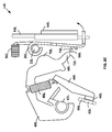
- FIG. 2A illustrates example internal components of first mechanical pole 14L.
- First mechanical pole 14L includes first handle 18L, first armature 20L disposed on a first armature pivot 22L, a first cradle 40L disposed on a first cradle pivot 42L, a first moveable bus 44L that includes a first moveable contact 46L and is coupled via a first spring 48L to first cradle 40L, and a first stationary bus 50L that includes a first stationary contact 52L disposed opposite first moveable contact 46L.
- a first compression spring 56L biases first armature 20L in a clockwise direction about first armature pivot 22L.
- First armature 20L includes a first projection 58L.
- First moveable bus 44L is connected to a first bi-metal strip 54L by a first flexible conductor 60L.
- a first load terminal 62L is connected to a top end of first bi-metal strip 54L, and also is coupled to a first short-circuit sensing element 64L.
- first bi-metal strip 54L and first short-circuit sensing element 64L are used to provide overcurrent and instantaneous tripping functions, respectively.
- a first channel 66L directs any arc discharge gas resulting from a short circuit away from first mechanical pole 14L.
- First cradle 40L includes a first end 68L disposed adjacent first projection 58L of first armature 20L, and a first cradle feature 70L adjacent first armature 20L.
- First handle 18L is coupled to an upper end of first moveable bus 44L, and may be used to selectively turn first mechanical pole 14L ON and OFF, and thereby selectively CLOSE and OPEN, respectively, first moveable contact 46L and first stationary contact 52L.
- moving first handle 18L to the ON position causes first moveable bus 44L to move in a clockwise direction, which causes first moveable contact 46L and first stationary contact 52L to CLOSE.
- moving first handle 18L to the OFF position causes first moveable bus 44L to move in a counter-clockwise direction, which causes first moveable contact 46L and first stationary contact 52L to OPEN.
- a latch system of first mechanical pole 14L activates when first handle 18L is moved from the OFF position to the ON position.
- first cradle 40L rotates counter-clockwise.
- first end 68L rotates past first projection 58L of first armature 20L.
- First armature 20L rotates clockwise towards first cradle 40L as a result of first compression spring 56L pushing on the top of first armature 20L, and first projection 58L of first armature 20L passes under first end 68L of first cradle 40L.
- first cradle 40L rotates clockwise until first end 68L of first cradle 40L engages first projection 58L of first armature 20L, latching first mechanical pole 14L ON.
- second mechanical pole 14R includes the same components as first mechanical pole 14L, albeit with "R" reference number designations. That is, second mechanical pole 14R includes second handle 18R, second armature 20R disposed on second armature pivot 22R, a second cradle 40R disposed on a second cradle pivot 42R, a second moveable bus 44R that includes a second moveable contact 46R and is coupled via a second spring 48R to second cradle 40R, and a second stationary bus 50R that includes a second stationary contact 52R disposed opposite second moveable contact 46R.
- a second compression spring 56R biases second armature 20R in a clockwise direction about second armature pivot 22R.
- Second armature 20R includes a second projection 58R.
- Second moveable bus 44R is connected to a second bi-metal strip 54R by a second flexible conductor 60R.
- a second load terminal 62R is connected to a top end of second bi-metal strip 54R, and also is coupled to a second short-circuit sensing element 64R.
- second bi-metal strip 54R and second short-circuit sensing element 64R are used to provide overcurrent and instantaneous tripping functions, respectively.
- a second channel 66R directs any arc discharge gas resulting from a short circuit away from second mechanical pole 14R.
- Second cradle 40R includes a second end 68R disposed adjacent second projection 58R of second armature 20R, and a second cradle feature 70R adjacent second armature 20R.
- Second handle 18R is coupled to an upper end of second moveable bus 44R, and may be used to selectively turn second mechanical pole 14R ON and OFF, and thereby selectively CLOSE and OPEN, respectively, second moveable contact 46R and second stationary contact 52R.
- moving second handle 18R to the ON position causes second moveable bus 44R to move in a clockwise direction, which causes second moveable contact 46R and second stationary contact 52R to CLOSE.
- moving second handle 18R to the OFF position causes second moveable bus 44R to move in a counter-clockwise direction, which causes second moveable contact 46R and second stationary contact 52R to OPEN.
- a latch system of second mechanical pole 14R activates when second handle 18R is moved from the OFF position to the ON position.
- second cradle 40R rotates counter-clockwise.
- second end 68R rotates past second projection 58R of second armature 20R.
- Second armature 20R rotates clockwise towards second cradle 40R as a result of second compression spring 56R pushing on the top of second armature 20R, and second projection 58R of second armature 20R passes under second end 68R of second cradle 40R.
- second cradle 40R rotates clockwise until second end 68R of second cradle 40R engages second projection 58R of second armature 20R, latching second mechanical pole 14R ON.
- FIG. 2B illustrates an enlarged view of select components of first mechanical pole 14L in the latched ON configuration.
- a first surface 72L of first end 68L makes engaging contact with a first top surface 74L of first projection 58L, preventing further clockwise rotation of first cradle 40L.
- first moveable bus 44L is adjacent first stationary bus 50L, and first movable contact 46L and first stationary contact 52L are CLOSED.
- First mechanical pole 14L remains latched ON until first handle 18L is moved to the OFF position, or until an overload condition or a short circuit condition causes the latch mechanism to disengage and trip first mechanical pole 14L.
- a ground fault and/or an arc fault also cause the latch mechanism to disengage and trip first mechanical pole 14L.
- first bi-metal strip 54L heat up and deflect, which causes first armature 20L to rotate in a counter-clockwise direction about first armature pivot 22L.
- first top surface 74L pulls away from first surface 72L, decreasing the overlap area of the two surfaces, as shown in FIG. 2C .
- first bi-metal strip 54L continues to heat up and deflect, first armature 20L further rotates about first armature pivot 22L, and the surface area overlap between first top surface 74L and first surface 72L continues to decrease.
- first cradle 40L rotates clockwise about first cradle pivot 42L, and first extension spring 48L rotates first moveable bus 44L counter-clockwise to separate first moveable contact 46L from first stationary contact 52L, unlatching first mechanical pole 14L.
- first movable contact 46L and first stationary contact 52L are OPEN, as shown in FIG. 2D .
- first short-circuit sensing element 64L causes a magnetic field of first short-circuit sensing element 64L to increase, which causes first armature 20L to rotate in a counter-clockwise direction about first armature pivot 22L, and the surface area overlap between first top surface 74L of first armature 20L and first surface 72L of first cradle 40L decreases to about zero.
- first cradle 40L rotates clockwise about first cradle pivot 42L
- first extension spring 48L rotates first moveable bus 44L counter-clockwise to separate first moveable contact 46L from first stationary contact 52L, unlatching first mechanical pole 14L.
- first movable contact 46L and first stationary contact 52L are OPEN, as shown in FIG. 2D .
- trip mechanism 30 is disposed in electronic pole 12 of circuit breaker 10.
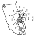
- a circuit board 80 is adapted to be mounted in electronic pole 12 (not shown), and includes a recess 82 adapted to receive trip mechanism 30.
- a solenoid 84 is disposed on circuit board 80, and includes a plunger 86 having a tip 88 adjacent recess 82.
- Trip mechanism 30 includes first trip arm 32L and second trip arm 32L disposed between a top element 102 a bottom element 104.
- first trip arm 32L includes first trip arm end 34L, a first trip arm journal 110L, and a first trip arm tab 112L
- second trip arm 32R includes second trip arm end 34R, a second trip arm journal 110R, and a second trip arm tab 112R
- First trip arm end 34L includes a first armature interface 114L and a first cradle interface 116L
- second trip arm end 34R includes a second armature interface 114R and a second cradle interface 116R.
- First trip arm tab 112L includes a first trip arm interface 118L, a first solenoid interface 120L and a first trip arm interface surface 122L
- second trip arm tab 112R includes a second trip arm interface 118R, a second solenoid interface 120R and a second trip arm interface surface 122R.
- Bottom element 104 includes a first post 124L for slidingly receiving first trip arm journal 110L, and a second post 124R for slidingly receiving second trip arm journal 110R.
- Top element 102 securingly attaches to bottom element 104, and constrains first trip arm 32L and second trip arm 32R.
- First trip arm 32L is adapted to rotate about first post 124L
- second trip arm 32R is adapted to rotate about second post 124R.
- first trip arm interface 118L engages second trip arm interface surface 122R, causing second trip arm 32R to rotate in an opposite (e.g., clockwise direction), and vice-versa.
- second trip arm interface 118R engages first trip arm interface surface 122L, causing first trip arm 32L to rotate in an opposite (e.g., counter-clockwise direction), and vice-versa.
- Bottom element 104 also may include side posts 126L, 126R, 128L and 128R for positioning and securing trip mechanism 30 in complementary journals (not shown) in electronic pole 12.
- trip mechanism 30 is disposed in recess 82 of circuit board 80.
- Tip 88 of solenoid 84 plunger 86 is disposed adjacent first solenoid interface 120L and second solenoid interface 120R.
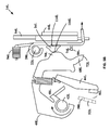
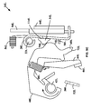
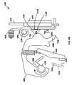
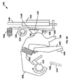
- FIGS. 4A-4E , 5A-5C and 6A-6C illustrate the operation of two-pole circuit breaker 10.
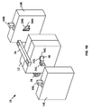
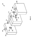
- FIG. 4A illustrates electronic pole 12 coupled between first mechanical pole 14L and second mechanical pole 14R to form two-pole circuit breaker 10.
- FIG. 5A illustrates a side internal view of first mechanical pole 14L
- FIG. 6A illustrates a side internal view second mechanical pole 14R.
- first mechanical pole 14L and second mechanical pole 14R are shown.
- FIG. 4A illustrates a top view of portions of electronic pole 12, first mechanical pole 14L and second mechanical pole 14R, with trip mechanism 30 disposed in electronic pole 12, first trip arm end 34L disposed in first mechanical pole 14L between first cradle 40L and first armature 20L, and second trip arm end 34R disposed in second mechanical pole 14R between second cradle 40R and second armature 20R.
- first trip arm end 34L does not make engaging contact with first cradle 40L or first armature 20L
- second trip arm end 34R does not make engaging contact with second cradle 40R or second armature 20R.
- first surface 72L of first end 68L makes engaging contact with first top surface 74L of first projection 58L
- first moveable bus 44L is adjacent first stationary bus 50L
- first movable contact 46L and first stationary contact 52L are CLOSED.
- second surface 72R of second end 68R makes engaging contact with second top surface 74R of second projection 58R
- second moveable bus 44R is adjacent second stationary bus 50R
- second movable contact 46R and second stationary contact 52R are CLOSED.
- first mechanical pole 14L if an overcurrent or short circuit occurs on first mechanical pole 14L, current flowing through the breaker causes first bi-metal strip 54L to heat up and deflect, which causes first armature 20L to rotate in a counter-clockwise direction about first armature pivot 22L.
- first cradle feature 70L engages first cradle interface 116L, which causes first trip arm 32L to rotate in a clockwise direction about first trip arm journal 110L.
- first trip arm interface 118L engages second trip arm interface surface 122R (not shown), causing second trip arm 32R to rotate in a counter-clockwise direction about second trip arm journal 110R.
- second armature interface 114R engages second armature 20R, causing second armature 20R to rotate in a counter-clockwise direction about second armature pivot 22R.
- rotation of first armature 22L in a first plane causes first trip arm 32L and second trip arm 32R to rotate in a second plane substantially orthogonal to the first plane, which in turn causes second armature 20R to rotate in the first plane.
- first armature 20L continues to rotate in a counter-clockwise direction about first armature pivot 22L
- second armature 20R continues to rotate in a counter-clockwise direction about second armature pivot 22R.
- First top surface 74L pulls away from first surface 72L
- second top surface 74R pulls away from second surface 72R.
- first cradle 40L rotates clockwise about first cradle pivot 42L
- first extension spring 48L rotates first moveable bus 44L counter-clockwise to separate first moveable contact 46L from first stationary contact 52L, unlatching first mechanical pole 14L, as shown in FIGS. 5B-5C .
- first movable contact 46L and first stationary contact 52L are OPEN, as shown in FIG. 5C .
- an upper end of first cradle feature 70L engages first trip arm end 34L so that first armature interface 114L remains engaged with first armature 20L.
- second cradle 40R rotates clockwise about second cradle pivot 42R
- second extension spring 48R rotates second moveable bus 44R counter-clockwise to separate second moveable contact 46R from second stationary contact 52R, unlatching second mechanical pole 14R, as shown in FIGS. 6B-6C .
- second movable contact 46R and second stationary contact 52R are OPEN, as shown in FIG. 6C .
- an upper end of second cradle feature 70R engages second trip arm end 34R so that second armature interface 114R remains engaged with second armature 20R.
- an overcurrent or short circuit fault on first mechanical pole 14L results in a common trip of first mechanical pole 14L and second mechanical pole 14R without using a trip bar.
- an overcurrent or short circuit fault on second mechanical pole 14R likewise results in a common trip of first mechanical pole 14L and second mechanical pole 14R without using a trip bar.
- two-pole circuit breakers in accordance with this invention also may trip on arc faults and/or ground faults.
- electronic pole 12 may include an arc fault and/or a ground fault detector circuit (not shown) that continuously monitors current flowing in each mechanical pole. Referring to FIG. 3C , if an arc fault or a ground fault occurs in first mechanical pole 14L or second mechanical pole 14R, the detector circuit activates solenoid 84 to trip and unlatch first mechanical pole 14L and second mechanical pole 14R without using a trip bar.
- first mechanical pole 14L or second mechanical pole 14R activates solenoid 84, which causes plunger 86 (not shown) and tip 88 to move towards and push against first solenoid interface 120L and second solenoid interface 120R.
- plunger 86 not shown
- tip 88 pushes against first solenoid interface 120L and second solenoid interface
- first trip arm 32L rotates in a clockwise direction about first trip arm journal 110L
- second trip arm 32R rotates in a counter-clockwise direction about second trip arm journal 110R.
- first trip arm 32L and second trip arm 32R rotate, first armature interface 114L engages first armature 20L, causing first armature 20L to rotate in a counter-clockwise direction about first armature pivot 22L, and second armature interface 114R engages second armature 20R, causing second armature 20R to rotate in a counter-clockwise direction about second armature pivot 22R.
- rotation of first trip arm 32L and second trip arm 32R in a second plane causes first armature 22L and second armature 20R to rotate in the first plane in a first plane substantially orthogonal to the second plane.
- first armature 20L continues to rotate in a counter-clockwise direction about first armature pivot 22L
- second armature 20R continues to rotate in a counter-clockwise direction about second armature pivot 22R.
- first top surface 74L pulls away from first surface 72L
- second top surface 74R pulls away from second surface 72R.
- first cradle 40L rotates clockwise about first cradle pivot 42L
- first extension spring 48L rotates first moveable bus 44L counter-clockwise to separate first moveable contact 46L from first stationary contact 52L, unlatching first mechanical pole 14L, as shown in FIGS. 5B-5C .
- first movable contact 46L and first stationary contact 52L are OPEN, as shown in FIG. 5C .
- an upper end of first cradle feature 70L engages first trip arm end 34L so that first armature interface 114L remains engaged with first armature 20L.
- second cradle 40R rotates clockwise about second cradle pivot 42R
- second extension spring 48R rotates second moveable bus 44R counter-clockwise to separate second moveable contact 46R from second stationary contact 52R, unlatching second mechanical pole 14R, as shown in FIGS. 6B-6C .
- second movable contact 46R and second stationary contact 52R are OPEN, as shown in FIG. 6C .
- an upper end of second cradle feature 70R engages second trip arm end 34R so that second armature interface 114R remains engaged with second armature 20R.
- an arc fault and/or a ground fault on first mechanical pole 14L or second mechanical pole 14R results in a common trip of first mechanical pole 14L and second mechanical pole 14R without using a trip bar.
- dimensions of second armature interface 114R may be selected to increase the moment arm and reduce the amount of force required to de-latch second armature 20R.
- dimensions of first armature interface 114L may be selected to increase the moment arm and reduce the amount of force required to de-latch first armature 20L.
Landscapes
- Breakers (AREA)
Applications Claiming Priority (1)
| Application Number | Priority Date | Filing Date | Title |
|---|---|---|---|
| US14/024,061 US8988174B1 (en) | 2013-09-11 | 2013-09-11 | Tripping mechanisms for two-pole circuit breakers |
Publications (2)
| Publication Number | Publication Date |
|---|---|
| EP2849197A2 true EP2849197A2 (de) | 2015-03-18 |
| EP2849197A3 EP2849197A3 (de) | 2015-08-19 |
Family
ID=51389951
Family Applications (1)
| Application Number | Title | Priority Date | Filing Date |
|---|---|---|---|
| EP14181445.9A Withdrawn EP2849197A3 (de) | 2013-09-11 | 2014-08-19 | Auslösungsmechanismen für zweipolige Schutzschalter |
Country Status (3)
| Country | Link |
|---|---|
| US (1) | US8988174B1 (de) |
| EP (1) | EP2849197A3 (de) |
| CN (1) | CN104681366B (de) |
Families Citing this family (1)
| Publication number | Priority date | Publication date | Assignee | Title |
|---|---|---|---|---|
| US9455110B2 (en) * | 2013-09-11 | 2016-09-27 | Siemens Industry, Inc. | Two-pole circuit breakers |
Family Cites Families (12)
| Publication number | Priority date | Publication date | Assignee | Title |
|---|---|---|---|---|
| BE379657A (de) * | 1930-05-28 | |||
| US3949331A (en) * | 1974-05-15 | 1976-04-06 | Westinghouse Electric Corporation | Circuit breaker with adjustable thermal trip unit |
| US3979704A (en) * | 1975-05-23 | 1976-09-07 | Westinghouse Electric Corporation | Circuit breaker having members coated with phosphate-chromate protective layers |
| US6239676B1 (en) * | 2000-08-28 | 2001-05-29 | Eaton Corporation | Two pole circuit breaker calibrated in assembled state |
| CA2499238A1 (en) * | 2004-03-04 | 2005-09-04 | Brian Timothy Mccoy | Enhanced solenoid-armature interface |
| US7515022B2 (en) | 2005-10-19 | 2009-04-07 | Eaton Corporation | Circuit breaker common trip lever |
| US8134428B2 (en) * | 2008-01-09 | 2012-03-13 | Siemens Industry, Inc. | Circuit breaker with electronic sensing and de-latch activation |
| US7986203B2 (en) * | 2008-02-19 | 2011-07-26 | Siemens Industry, Inc. | Multi-pole armature interlock for circuit breakers |
| US8049122B2 (en) * | 2008-02-19 | 2011-11-01 | Siemens Industry, Inc. | Moisture resistant push to test button for circuit breakers |
| US8369052B2 (en) * | 2008-07-25 | 2013-02-05 | Siemens Industry, Inc. | Modular circuit breaker |
| US8267562B2 (en) * | 2009-03-18 | 2012-09-18 | Siemens Industry, Inc. | Multi-pole circuit breaker light guide trip indicator and installation method |
| US8241074B2 (en) * | 2009-03-18 | 2012-08-14 | Siemens Industry, Inc. | Circuit breakers with lug screw retention and methods for manufacturing same |
-
2013
- 2013-09-11 US US14/024,061 patent/US8988174B1/en not_active Expired - Fee Related
-
2014
- 2014-08-19 EP EP14181445.9A patent/EP2849197A3/de not_active Withdrawn
- 2014-09-11 CN CN201410459333.0A patent/CN104681366B/zh not_active Expired - Fee Related
Non-Patent Citations (1)
| Title |
|---|
| None |
Also Published As
| Publication number | Publication date |
|---|---|
| US8988174B1 (en) | 2015-03-24 |
| CN104681366B (zh) | 2019-03-01 |
| CN104681366A (zh) | 2015-06-03 |
| EP2849197A3 (de) | 2015-08-19 |
| US20150070113A1 (en) | 2015-03-12 |
Similar Documents
| Publication | Publication Date | Title |
|---|---|---|
| US8264306B2 (en) | Movable contactor assembly for current limiting type molded case circuit breaker | |
| KR101968181B1 (ko) | 잔여 전류 릴리스 장치를 구비한 저압 차단기 | |
| KR101823516B1 (ko) | 직류 배선용 차단기의 트립 장치 | |
| CA2966097C (en) | Modular circuit breaker and method of assembling | |
| ES2905880T3 (es) | Disyuntor con mecanismo de desconexión instantánea | |
| JP6468504B2 (ja) | 直流配線用遮断器 | |
| EP2851925B1 (de) | Zweipolige Schutzschalter | |
| US9214309B2 (en) | Two-pole circuit breaker with trip bar apparatus and methods | |
| JP4123081B2 (ja) | 漏電遮断器 | |
| JP4085911B2 (ja) | 漏電遮断器 | |
| CN1767121B (zh) | 漏电断路器 | |
| JP4839772B2 (ja) | 耐電圧テスト用スイッチおよび漏電遮断器 | |
| WO2012119555A1 (zh) | 优化空间分配的断路器 | |
| JPWO2001071750A1 (ja) | 回路遮断器 | |
| CN104681366A (zh) | 用于两极断路器的脱扣机构 | |
| CN1841616B (zh) | 漏电断路器 | |
| JP4972998B2 (ja) | 漏電遮断器 | |
| CA2796916C (en) | Electrical switching apparatus including two poles and a single operating handle | |
| JP4856518B2 (ja) | 回路遮断器 | |
| US9818567B1 (en) | Apparatus and method of reducing arcing between a circuit breaker line terminal and a panel board terminal | |
| CN218384897U (zh) | 电路结构及断路器 | |
| JP2003297218A (ja) | 漏電遮断器 | |
| CN108899259A (zh) | 漏电保护断路器 | |
| KR101498253B1 (ko) | 소형 누전 및 배선용 차단기 | |
| CN206353511U (zh) | 一种自动重合闸断路器 |
Legal Events
| Date | Code | Title | Description |
|---|---|---|---|
| PUAI | Public reference made under article 153(3) epc to a published international application that has entered the european phase |
Free format text: ORIGINAL CODE: 0009012 |
|
| 17P | Request for examination filed |
Effective date: 20140819 |
|
| AK | Designated contracting states |
Kind code of ref document: A2 Designated state(s): AL AT BE BG CH CY CZ DE DK EE ES FI FR GB GR HR HU IE IS IT LI LT LU LV MC MK MT NL NO PL PT RO RS SE SI SK SM TR |
|
| AX | Request for extension of the european patent |
Extension state: BA ME |
|
| RIC1 | Information provided on ipc code assigned before grant |
Ipc: H01H 71/10 20060101AFI20150327BHEP Ipc: H01H 83/20 20060101ALI20150327BHEP |
|
| PUAL | Search report despatched |
Free format text: ORIGINAL CODE: 0009013 |
|
| AK | Designated contracting states |
Kind code of ref document: A3 Designated state(s): AL AT BE BG CH CY CZ DE DK EE ES FI FR GB GR HR HU IE IS IT LI LT LU LV MC MK MT NL NO PL PT RO RS SE SI SK SM TR |
|
| AX | Request for extension of the european patent |
Extension state: BA ME |
|
| RIC1 | Information provided on ipc code assigned before grant |
Ipc: H01H 71/10 20060101AFI20150714BHEP Ipc: H01H 83/20 20060101ALI20150714BHEP |
|
| R17P | Request for examination filed (corrected) |
Effective date: 20160216 |
|
| RBV | Designated contracting states (corrected) |
Designated state(s): AL AT BE BG CH CY CZ DE DK EE ES FI FR GB GR HR HU IE IS IT LI LT LU LV MC MK MT NL NO PL PT RO RS SE SI SK SM TR |
|
| RAP1 | Party data changed (applicant data changed or rights of an application transferred) |
Owner name: SIEMENS INDUSTRY, INC. |
|
| GRAP | Despatch of communication of intention to grant a patent |
Free format text: ORIGINAL CODE: EPIDOSNIGR1 |
|
| STAA | Information on the status of an ep patent application or granted ep patent |
Free format text: STATUS: GRANT OF PATENT IS INTENDED |
|
| INTG | Intention to grant announced |
Effective date: 20180130 |
|
| RIN1 | Information on inventor provided before grant (corrected) |
Inventor name: WATFORD, RUSSELL THOMAS |
|
| STAA | Information on the status of an ep patent application or granted ep patent |
Free format text: STATUS: THE APPLICATION IS DEEMED TO BE WITHDRAWN |
|
| 18D | Application deemed to be withdrawn |
Effective date: 20180612 |