EP2851925B1 - Zweipolige Schutzschalter - Google Patents
Zweipolige Schutzschalter Download PDFInfo
- Publication number
- EP2851925B1 EP2851925B1 EP14181444.2A EP14181444A EP2851925B1 EP 2851925 B1 EP2851925 B1 EP 2851925B1 EP 14181444 A EP14181444 A EP 14181444A EP 2851925 B1 EP2851925 B1 EP 2851925B1
- Authority
- EP
- European Patent Office
- Prior art keywords
- pole
- trip
- mechanical
- circuit
- mechanical pole
- Prior art date
- Legal status (The legal status is an assumption and is not a legal conclusion. Google has not performed a legal analysis and makes no representation as to the accuracy of the status listed.)
- Active
Links
Images








Classifications
-
- H—ELECTRICITY
- H01—ELECTRIC ELEMENTS
- H01H—ELECTRIC SWITCHES; RELAYS; SELECTORS; EMERGENCY PROTECTIVE DEVICES
- H01H73/00—Protective overload circuit-breaking switches in which excess current opens the contacts by automatic release of mechanical energy stored by previous operation of a hand reset mechanism
-
- H—ELECTRICITY
- H01—ELECTRIC ELEMENTS
- H01H—ELECTRIC SWITCHES; RELAYS; SELECTORS; EMERGENCY PROTECTIVE DEVICES
- H01H71/00—Details of the protective switches or relays covered by groups H01H73/00 - H01H83/00
- H01H71/10—Operating or release mechanisms
- H01H71/1009—Interconnected mechanisms
-
- H—ELECTRICITY
- H01—ELECTRIC ELEMENTS
- H01H—ELECTRIC SWITCHES; RELAYS; SELECTORS; EMERGENCY PROTECTIVE DEVICES
- H01H83/00—Protective switches, e.g. circuit-breaking switches, or protective relays operated by abnormal electrical conditions otherwise than solely by excess current
- H01H83/20—Protective switches, e.g. circuit-breaking switches, or protective relays operated by abnormal electrical conditions otherwise than solely by excess current operated by excess current as well as by some other abnormal electrical condition
- H01H83/22—Protective switches, e.g. circuit-breaking switches, or protective relays operated by abnormal electrical conditions otherwise than solely by excess current operated by excess current as well as by some other abnormal electrical condition the other condition being imbalance of two or more currents or voltages
- H01H83/226—Protective switches, e.g. circuit-breaking switches, or protective relays operated by abnormal electrical conditions otherwise than solely by excess current operated by excess current as well as by some other abnormal electrical condition the other condition being imbalance of two or more currents or voltages with differential transformer
-
- H—ELECTRICITY
- H02—GENERATION; CONVERSION OR DISTRIBUTION OF ELECTRIC POWER
- H02H—EMERGENCY PROTECTIVE CIRCUIT ARRANGEMENTS
- H02H3/00—Emergency protective circuit arrangements for automatic disconnection directly responsive to an undesired change from normal electric working condition with or without subsequent reconnection ; integrated protection
-
- H—ELECTRICITY
- H02—GENERATION; CONVERSION OR DISTRIBUTION OF ELECTRIC POWER
- H02H—EMERGENCY PROTECTIVE CIRCUIT ARRANGEMENTS
- H02H3/00—Emergency protective circuit arrangements for automatic disconnection directly responsive to an undesired change from normal electric working condition with or without subsequent reconnection ; integrated protection
- H02H3/08—Emergency protective circuit arrangements for automatic disconnection directly responsive to an undesired change from normal electric working condition with or without subsequent reconnection ; integrated protection responsive to excess current
- H02H3/10—Emergency protective circuit arrangements for automatic disconnection directly responsive to an undesired change from normal electric working condition with or without subsequent reconnection ; integrated protection responsive to excess current additionally responsive to some other abnormal electrical conditions
-
- H—ELECTRICITY
- H02—GENERATION; CONVERSION OR DISTRIBUTION OF ELECTRIC POWER
- H02H—EMERGENCY PROTECTIVE CIRCUIT ARRANGEMENTS
- H02H3/00—Emergency protective circuit arrangements for automatic disconnection directly responsive to an undesired change from normal electric working condition with or without subsequent reconnection ; integrated protection
- H02H3/16—Emergency protective circuit arrangements for automatic disconnection directly responsive to an undesired change from normal electric working condition with or without subsequent reconnection ; integrated protection responsive to fault current to earth, frame or mass
-
- H—ELECTRICITY
- H01—ELECTRIC ELEMENTS
- H01H—ELECTRIC SWITCHES; RELAYS; SELECTORS; EMERGENCY PROTECTIVE DEVICES
- H01H71/00—Details of the protective switches or relays covered by groups H01H73/00 - H01H83/00
- H01H71/10—Operating or release mechanisms
- H01H71/12—Automatic release mechanisms with or without manual release
- H01H71/123—Automatic release mechanisms with or without manual release using a solid-state trip unit
- H01H2071/124—Automatic release mechanisms with or without manual release using a solid-state trip unit with a hybrid structure, the solid state trip device being combined with a thermal or a electromagnetic trip
Definitions
- Example embodiments include ground fault circuit interrupt two-pole residential circuit breakers, arc fault circuit interrupt two-pole residential circuit breakers, and combination arc fault and ground fault circuit interrupt two-pole residential circuit breakers.
- US 2010/020453 A1 describes a modular two-pole circuit breaker using an electronic pole comprising a common trip bar extending from the first circuit breaker pole, through the electronic pole, and into the second circuit breaker pole which cause to trip both circuit breaker poles.
- US 2010/020453 A1 further describes the electronic pole comprising an electronic trip circuitry comprising an arc fault and ground fault detection circuitry.
- US 2005/073780 A1 describes a two line electric power distribution system with a circuit breaker pole in each line which are connected together so that a fault signal open both poles in response to a fault in either line.
- US 2005/103613 A1 describes a circuit breaker with a thermal or magnetic trip device which light up indicators of the type of trip, or a failure to trip.
- a two-pole circuit breaker in a first aspect, includes a first mechanical pole, a second mechanical pole and an electronic pole.
- the first mechanical pole includes a first armature having a first armature extension
- the second mechanical pole includes a second armature having a second armature extension.
- the electronic pole includes a first solenoid and a second solenoid, the first armature extension is disposed adjacent the first solenoid, and the second armature is disposed adjacent the second solenoid.
- the electronic pole includes a trip detection circuit.
- the trip detection circuit comprises a first current and voltage monitor circuit that monitors a first current and a first voltage on the first mechanical pole and the trip detection circuit generates a first trip signal to trip the second mechanical pole when the first current and the first voltage are substantially zero.
- the trip detection circuit comprises a second current and voltage monitor circuit that monitors a second current and a second voltage on the second mechanical pole and the trip detection circuit generates a second trip signal to trip the first mechanical pole when the second current and the second voltage are substantially zero.
- the other pole also trips, known as a common trip.
- the two-pole circuit breaker does not include a trip bar.
- an electronic pole for use with a two-pole circuit breaker having a first mechanical pole and a second mechanical pole.
- the electronic pole includes a trip detection circuit having a first output signal node and a second output signal node, a first trip generator circuit having an input coupled to the first output signal node, and a second trip generator circuit having an input coupled to the second output signal node.
- the trip detection circuit provides a first output signal on the first output signal node when the first mechanical pole trips, and provides a second output signal on the second output signal node when the second mechanical pole trips.
- the trip detection circuit comprises a first current and voltage monitor circuit that monitors a first current and a first voltage on the first mechanical pole and the trip detection circuit generates a first trip signal to trip the second mechanical pole when the first current and the first voltage are substantially zero.
- the trip detection circuit comprises a second current and voltage monitor circuit that monitors a second current and a second voltage on the second mechanical pole and the trip detection circuit generates a second trip signal to trip the first mechanical pole when the second current and the second voltage are substantially zero.
- the other pole also trips, known as a common trip.
- a two-pole circuit breaker in a third aspect, includes a first mechanical pole, a second mechanical pole and an electronic pole.
- the electronic pole includes a trip detection circuit that has a fault detection circuit coupled to a first trip detector circuit and a second trip detector circuit.
- the trip detection circuit comprises a first current and voltage monitor circuit that monitors a first current and a first voltage on the first mechanical pole and the trip detection circuit generates a first trip signal to trip the second mechanical pole when the first current and the first voltage are substantially zero.
- the trip detection circuit comprises a second current and voltage monitor circuit that monitors a second current and a second voltage on the second mechanical pole and the trip detection circuit generates a second trip signal to trip the first mechanical pole when the second current and the second voltage are substantially zero.
- the other pole also trips, known as a common trip.
- Two-pole circuit breakers such as residential twopole circuit breakers, have two electrical branches or poles through which electrical power is provided to one or more loads.
- residential two-pole circuit breakers typically provide 240 volts instead of 120 volts to devices or appliances such as electric dryers, water heaters, well pumps, and/or electric ranges.
- Previously known two-pole circuit breakers typically include an electronic pole disposed between first and second mechanical poles.
- a trip bar typically extends through the electronic pole and communicates with the first and second mechanical poles.
- the electronic pole may include an arc fault or a ground fault detector circuit that continuously monitors current flowing in each mechanical pole. If an arc fault or a ground fault occurs in either mechanical pole, the detector circuit activates a single wound solenoid to trip and unlatch the faulted mechanical pole. As the faulted mechanical pole unlatches, the trip bar rotates, and the rotation causes the other mechanical pole to trip and unlatch.
- trip bar may require several production instructions during manufacture, and special fixtures may be needed to ensure that the trip bar is correctly assembled.
- key features of the trip bar may have very tight tolerances that need close monitoring to ensure that required drawing specifications are satisfied.
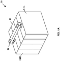
- Example circuit breaker 10 includes an electronic pole 12 disposed between a first mechanical pole 14L and a second mechanical pole 14R, and a handle tie bar 16 coupled to first and second handles 18L and 18R, respectively, on first mechanical pole 14L and second mechanical pole 14R, respectively.
- Handle tie bar 16 may be used to simultaneously operate first and second handles 18L and 18R, respectively, to turn circuit breaker 10 ON and OFF.
- the electronic pole 12 may be otherwise located (e.g., not between the first and second mechanical poles 14L and 14R, such as behind or in front one or both of the mechanical poles 14L and 14R).
- First mechanical pole 14L includes a first armature 20L disposed on a first armature pivot 22L, and includes a first armature extension 24L that extends through a first mechanical pole aperture 26L.
- Second mechanical pole 14R includes a second armature 20R disposed on a second armature pivot 22R, and includes a second armature extension 24R that extends through a second mechanical pole aperture 26R.
- electronic pole 12 includes a first aperture 30L and a second aperture 30R.
- a first solenoid plunger 32L having a tip 34L is disposed in first aperture 30L
- a second solenoid plunger 32R having a tip 34R is disposed in second aperture 30R.
- electronic pole 12 optionally includes a pigtail 36 which may be used to connect a neutral conductor (not shown) in circuit breaker 10 to a load center or panel board neutral bar (not shown).
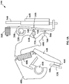
- FIG. 2A illustrates example internal components of first mechanical pole 14L.
- First mechanical pole 14L includes first handle 18L, first armature 20L disposed on first armature pivot 22L, a first cradle 40L disposed on a first cradle pivot 42L, a first moveable bus 44L that includes a first moveable contact 46L and is coupled via a first spring 48L to first cradle 40L, and a first stationary bus 50L that includes a first stationary contact 52L disposed opposite first moveable contact 46L.
- a first compression spring 56L biases first armature 20L in a clockwise direction about first armature pivot 22L.
- First armature 20L includes first armature extension 24L and a first projection 58L.
- First moveable bus 44L is connected to a first bi-metal strip 54L by a first flexible conductor 60L.
- a first load terminal 62L is connected to a top end of first bi-metal strip 54L, and also is coupled to a first short-circuit sensing element 64L.
- first bi-metal strip 54L and first short-circuit sensing element 64L are used to provide overcurrent and instantaneous tripping functions, respectively.
- a first channel 66L directs any arc discharge gas resulting from a short circuit away from first mechanical pole 14L.
- First cradle 40L includes a first end 68L disposed adjacent first projection 58L of first armature 20L.
- First handle 18L is coupled to an upper end of first moveable bus 44L, and may be used to selectively turn first mechanical pole 14L ON and OFF, and thereby selectively CLOSE and OPEN, respectively, first moveable contact 46L and first stationary contact 52L.
- moving first handle 18L to the ON position causes first moveable bus 44L to move in a clockwise direction, which causes first moveable contact 46L and first stationary contact 52L to CLOSE.
- moving first handle 18L to the OFF position causes first moveable bus 44L to move in a counter-clockwise direction, which causes first moveable contact 46L and first stationary contact 52L to OPEN.
- a latch system of first mechanical pole 14L activates when first handle 18L is moved from the OFF position to the ON position.
- first cradle 40L rotates counter-clockwise.
- first end 68L rotates past first projection 58L of first armature 20L.
- First armature 20L rotates clockwise towards first cradle 40L as a result of first compression spring 56L pushing on the top of first armature 20L, and first projection 58L of first armature 20L passes under first end 68L of first cradle 40L.
- first cradle 40L rotates clockwise until first end 68L of first cradle 40L engages first projection 58L of first armature 20L, latching first mechanical pole 14L ON.
- second mechanical pole 14R includes the same components as first mechanical pole 14L, albeit with "R" reference number designations. That is, second mechanical pole 14R includes handle 18R, second armature 20R disposed on second armature pivot 22R, a second cradle 40R disposed on a second cradle pivot 42R, a second moveable bus 44R that includes a second moveable contact 46R and is coupled via a second spring 48R to second cradle 40R, and a second stationary bus 50R that includes a second stationary contact 52R disposed opposite second moveable contact 46R.
- a second compression spring 56R biases second armature 20R in a clockwise direction about second armature pivot 22R.
- Second armature 20R includes second armature extension 24R and a second projection 58R.
- Second moveable bus 44R is connected to a second bi-metal strip 54R by a second flexible conductor 60R.
- a second load terminal 62R is connected to a top end of second bi-metal strip 54R, and also is coupled to a second short-circuit sensing element 64R.
- second bi-metal strip 54R and second short-circuit sensing element 64R are used to provide overcurrent and instantaneous tripping functions, respectively.
- a second channel 66R directs any arc discharge gas resulting from a short circuit away from second mechanical pole 14R.
- Second cradle 40R includes a second end 68R disposed adjacent second projection 58R of second armature 20R.
- Second handle 18R is coupled to an upper end of second moveable bus 44R, and may be used to selectively turn second mechanical pole 14R ON and OFF, and thereby selectively CLOSE and OPEN, respectively, second moveable contact 46R and second stationary contact 52R.
- moving second handle 18R to the ON position causes second moveable bus 44R to move in a clockwise direction, which causes second moveable contact 46R and second stationary contact 52R to CLOSE.
- moving second handle 18R to the OFF position causes second moveable bus 44R to move in a counter-clockwise direction, which causes second moveable contact 46R and second stationary contact 52L to OPEN.
- a latch system of second mechanical pole 14R activates when second handle 18R is moved from the OFF position to the ON position.
- second cradle 40R rotates counter-clockwise.
- second end 68R rotates past second projection 58R of second armature 20L.
- Second armature 20R rotates clockwise towards second cradle 40R as a result of second compression spring 56R pushing on the top of second armature 20R, and second projection 58R of second armature 20R passes under second end 68R of second cradle 40R.
- second cradle 40R rotates clockwise until second end 68R of second cradle 40R engages second projection 58R of second armature 20R, latching second mechanical pole 14R ON.
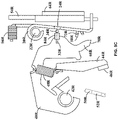
- FIG. 2B illustrates an enlarged view of select components of first mechanical pole 14L in the latched ON configuration.
- a first surface 70L of first end 68L makes engaging contact with a first top surface 72L of first projection 58L, preventing further clockwise rotation of first cradle 40L.
- first moveable bus 44L is adjacent first stationary bus 50L, and first movable contact 46L and first stationary contact 52L are CLOSED.
- First mechanical pole 14L remains latched ON until first handle 18L is moved to the OFF position, or until an overload condition or a short circuit condition causes the latch mechanism to disengage and trip first mechanical pole 14L.
- a ground fault and/or an arc fault also cause the latch mechanism to disengage and trip first mechanical pole 14L.
- first bi-metal strip 54L heat up and deflect, which causes first armature 20L to rotate in a counter-clockwise direction about first armature pivot 22L.
- first top surface 72L pulls away from first surface 70L, decreasing the overlap area of the two surfaces, as shown in FIG. 2C .
- first bi-metal strip 54L continues to heat up and deflect, first armature 20L further rotates about first armature pivot 22L, and the surface area overlap between first top surface 72L and first surface 70L continues to decrease.
- first cradle 40L rotates clockwise about first cradle pivot 42L, and first extension spring 48L rotates first moveable bus 44L counter-clockwise to separate first moveable contact 46L from first stationary contact 52L, unlatching first mechanical pole 14L.
- first movable contact 46L and first stationary contact 52L are OPEN, as shown in FIG. 2D .
- first short-circuit sensing element 64L causes a magnetic field of first short-circuit sensing element 64L to increase, which causes first armature 20L to rotate in a counter-clockwise direction about first armature pivot 22L, and the surface area overlap between first top surface 72L of first armature 20L and first surface 70L of first cradle 40L decreases to about zero.
- first cradle 40L rotates clockwise about first cradle pivot 42L
- first extension spring 48L rotates first moveable bus 44L counter-clockwise to separate first moveable contact 46L from first stationary contact 52L, unlatching first mechanical pole 14L.
- first movable contact 46L and first stationary contact 52L are OPEN, as shown in FIG. 2D .
- Electronic pole 12 includes fault and trip detection circuit 80, and first and second trip generator circuits 82a and 82b, respectively.
- electronic pole 12 includes a first solenoid 84L disposed in first aperture 30L and a second solenoid 84R disposed in second aperture 30R.
- First solenoid 84L includes first solenoid plunger 32L having tip 34L
- second solenoid 84R includes second solenoid plunger 32R having tip 34R.
- electronic poles typically include components in addition to the ones illustrated in FIG. 3 . Such additional components have been omitted to avoid cluttering the drawing.
- fault and trip detection circuit 80 monitors current and voltage on first and second mechanical poles 14L and 14R, respectively. If fault and trip detection circuit 80 detects no current or voltage on second mechanical pole 14R, fault and trip detection circuit 80 generates a first trip signal T A that has a value (e.g., HIGH) that causes first trip generator circuit 82a to energize first solenoid 84L to trip first mechanical pole 14L. In this regard, two-pole circuit breaker 10 common trips without using a trip bar. Otherwise, first trip signal T A has a second value (e.g., LOW), and first trip generator circuit 82a does not energize second solenoid 84L.
- first trip signal T A has a second value (e.g., LOW)
- first trip generator circuit 82a does not energize second solenoid 84L.
- fault and trip detection circuit 80 detects no current or voltage on first mechanical pole 14L, fault and trip detection circuit 80 generates a second trip signal T B that has a first value (e.g., HIGH) that causes second trip generator circuit 82b to energize second solenoid 84R to trip second mechanical pole 14R. Otherwise, second trip signal T B has a second value (e.g., LOW), and second trip generator circuit 82b does not energize second solenoid 84R.
- first value e.g., HIGH
- second trip generator circuit 82b does not energize second solenoid 84R.
- fault and trip detection circuit 80 also may include hardware and/or software for ground fault and/or arc fault detection. In such embodiments, if fault and trip detection circuit 80 detects a ground fault and/or an arc fault on first mechanical pole 14L or second mechanical pole 14R, fault and trip detection circuit 80 generates first and second trip signals T A and T B that each have a first value (e.g., HIGH) that cause first trip generator circuit 82a to energize first solenoid 84L to trip first mechanical pole 14L and second trip generator circuit 82b to energize second solenoid 84R to trip second mechanical pole 14R.
- first value e.g., HIGH
- FIGS. 4A-4E illustrate the operation of two-pole circuit breaker 10.
- FIG. 4A illustrates electronic pole 12 coupled between first mechanical pole 14L and second mechanical pole 14R to form two-pole circuit breaker 10.
- first mechanical pole 14L and second mechanical pole 14R are shown, and connections to a neutral bus are not shown.
- neutral bus is not shown.
- Persons of ordinary skill in the art will understand that electronic pole 12 typically will be coupled to a neutral bus, as described below.
- First mechanical pole 14L is coupled to first line and load terminals ⁇ ALI and ⁇ ALD , respectively, and second mechanical pole 14R is coupled to second line and load terminals ⁇ BLI and ⁇ BLD , respectively.
- First armature extension 24L of first mechanical pole 14L extends into first aperture 30L of electronic pole 12, and is disposed adjacent tip 34L of solenoid plunger 32L.
- Second armature extension 24R of second mechanical pole 14R extends into second aperture 30R of electronic pole 12, and is disposed adjacent tip 34R of solenoid plunger 32R.
- Fault and trip detection circuit 80 is coupled to load terminals ⁇ BLI and ⁇ BLD .
- First armature 20L is coupled to first moveable contact 46L
- second armature 20R is coupled to second moveable contact 46R.
- first mechanical pole 14L is latched ON, with first moveable contact 46L and first stationary contact 52L CLOSED
- second mechanical pole 14R is latched ON, with second moveable contact 46R and second stationary contact 52R CLOSED.
- first line and load terminals ⁇ ALI and ⁇ ALD are coupled together
- second line and load terminals ⁇ BLI and ⁇ BLD respectively, are coupled together.
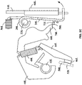
- FIG. 5A illustrates a view of selected components of electronic pole 12 and second mechanical pole 14R in this configuration.
- Persons of ordinary skill in the art will understand that the configuration of electronic pole 12 and first mechanical pole 14L is similar, albeit with "L" reference numbers.
- fault and trip detection circuit 80 detects no current and no voltage on first mechanical pole 14L, and generates second trip signal T B having a first value (e.g., HIGH) that causes second trip generator circuit 82b to energize second solenoid 84R.
- first value e.g., HIGH
- second solenoid 84R is energized, tip 34R of solenoid plunger 32R moves towards and pushes against second armature extension 24R of second mechanical pole 14R.
- second armature 20R rotates in a counter-clockwise direction about second armature pivot 22R, and the surface area overlap between second top surface 72R of second armature 20R and second surface 70R of second cradle 40R decreases to about zero.
- second cradle 40R rotates clockwise about second cradle pivot 42R, and second extension spring 48R rotates second moveable bus 44R counter-clockwise to separate second moveable contact 46R from second stationary contact 52R, unlatching second mechanical pole 14R.
- an overcurrent or short circuit fault on first mechanical pole 14L results in a common trip of first mechanical pole 14L and second mechanical pole 14R without using a trip bar.
- fault and trip detection circuit 80 detects no current and no voltage on second mechanical pole 14R, and generates first trip signal T A having a first value (e.g., HIGH) that causes first trip generator circuit 82a to energize first solenoid 84L.
- first solenoid 84L is energized, tip 34L of solenoid plunger 32L moves towards and pushes against first armature extension 24L of first mechanical pole 14L.
- first armature 20L rotates in a counter-clockwise direction about first armature pivot 22L, and the surface area overlap between first top surface 72L of first armature 20L and first surface 70L of first cradle 40L decreases to about zero.
- first cradle 40L rotates clockwise about first cradle pivot 42L, and first extension spring 48L rotates first moveable bus 44L counter-clockwise to separate first moveable contact 46L from first stationary contact 52L, unlatching first mechanical pole 14L.
- a overcurrent or short circuit fault on second mechanical pole 14R results in a common trip of first mechanical pole 14L and second mechanical pole 14R without using a trip bar.
- fault and trip detection circuit 80 includes hardware and/or software for ground fault and/or arc fault detection, and if fault and trip detection circuit 80 detects an arc fault or a ground on first mechanical pole 14L and/or second mechanical pole 14R, fault and trip detection circuit 80 generates first and second trip signals T A and T B that each have a first value (e.g., HIGH) that cause first trip generator circuit 82a to energize first solenoid 84L, and second trip generator circuit 82b to energize second solenoid 84R.
- first value e.g., HIGH
- tip 34L of solenoid plunger 32L moves towards and pushes against first armature extension 24L of first mechanical pole 14L
- tip 34R of solenoid plunger 32R moves towards and pushes against second armature extension 24R of second mechanical pole 14R.
- first moveable contact 46L separates from first stationary contact 52L, unlatching first mechanical pole 14L
- second moveable contact 46R separates from second stationary contact 52R, unlatching second mechanical pole 14R.
- an arc fault or a ground fault on first mechanical pole 14L and/or second mechanical pole 14R results in a common trip of first mechanical pole 14L and second mechanical pole 14R without using a trip bar.
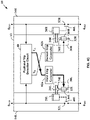
- fault and trip detection circuit 80 may generate a single common trip signal T C coupled to first trip generator circuit 82a and second trip generator circuit 82b, as shown in FIG. 4E . If fault and trip detection circuit 80 detects no current and no voltage on first mechanical pole 14L, or no current and no voltage on second mechanical pole 14R, or an arc fault or a ground fault occur on first mechanical pole 14L and/or second mechanical pole 14R, fault and trip detection circuit 80 generates common trip signal T C that has a first value (e.g., HIGH) that causes first trip generator circuit 82a to energize first solenoid 84L, and second trip generator circuit 82b to energize second solenoid 84R.
- a first value e.g., HIGH
- first moveable contact 46L separates from first stationary contact 52L, unlatching first mechanical pole 14L
- second moveable contact 46R separates from second stationary contact 52R, unlatching second mechanical pole 14R.
- an overcurrent or short circuit, or an arc fault or a ground fault on first mechanical pole 14L and/or second mechanical pole 14R results in a common trip of first mechanical pole 14L and second mechanical pole 14R without using a trip bar.
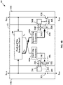
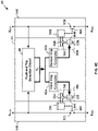
- example electronic pole 12 includes fault and trip detection circuit 80, and first and second trip generator circuits 82a and 82b, respectively.
- first solenoid 84L, second solenoid 84R and first and second armatures 20L and 20R, respectively, are not shown.
- Fault and trip detection circuit 80 includes a fault detection circuit 90, a first trip detector circuit 92a and a second trip detector circuit 92b.
- Fault detection circuit 90 is coupled to load terminals ⁇ ALD , and ⁇ BLD and a load side of neutral terminal N LD .
- Fault detection circuit 90 monitors current and voltage on first and second mechanical poles 14L and 14R, respectively.
- Fault detection circuit 90 generates an output signal T AB that is coupled to first trip detector circuit 92a and second trip detector circuit 92b.
- output signal T AB has a first value (e.g., HIGH). Otherwise, output signal T AB has a second value (e.g., LOW).
- First trip detector circuit 92a monitors current and voltage on first mechanical pole 14L. If first trip detector circuit 92a detects no current or voltage on first mechanical pole 14L, or receives a signal T AB having a first value (e.g., HIGH) from fault detection circuit 90, first trip detector circuit 92a generates second trip signal T B having a first value (e.g., HIGH) that causes second trip generator circuit 82b to trip second mechanical pole 14R.
- first trip detector circuit 92a monitors current and voltage on first mechanical pole 14L. If first trip detector circuit 92a detects no current or voltage on first mechanical pole 14L, or receives a signal T AB having a first value (e.g., HIGH) from fault detection circuit 90, first trip detector circuit 92a generates second trip signal T B having a first value (e.g., HIGH) that causes second trip generator circuit 82b to trip second mechanical pole 14R.
- second trip detector circuit 92b monitors current and voltage on second mechanical pole 14R. If second trip detector circuit 92b detects no current or voltage on second mechanical pole 14R, or receives a signal T AB having a first value (e.g., HIGH) from fault detection circuit 90, second trip detector circuit 92b generates first trip signal T A having a first value (e.g., HIGH) that causes first trip generator circuit 82a to trip first mechanical pole 14L.
- first value e.g., HIGH
- fault detection circuit 90 includes a fault detector 100 and a differential current detector circuit 102, and optionally includes a first RF generator circuit 104a and a second RF generator circuit 104b.
- Fault detector 100 may be a microprocessor or other similar processing device that may be used to detect ground faults and/or arc faults on load terminals ⁇ ALD , and ⁇ BLD .
- Differential current detector circuit 102 has inputs coupled to load terminals ⁇ ALD and ⁇ BLD , and load side neutral terminal N LD , and has an output ⁇ I S coupled to fault detector 100.
- Differential current detector circuit 102 senses current imbalances ⁇ I S in the line and neutral conductors resulting from ground leakage current through an unintended ground circuit path other than the neutral conductor.
- Fault detector 100 interprets a non-zero ⁇ I S signal as a ground fault, and generates signal T AB that has a first value (e.g., HIGH) to trip first mechanical pole 14L and second mechanical pole 14R.
- fault detection circuit 90 includes first RF generator circuit 104a and second RF generator circuit 104b.
- First RF generator circuit 104a is coupled to load terminal ⁇ ALD , and provides a first RF output signal V RFA to fault detector 100.
- Second RF generator circuit 104b is coupled to load terminal ⁇ BLD , and provides a second RF output signal V RFB to fault detector 100.
- Fault detector 100 analyzes differential current signal ⁇ I S , and first and second RF output signals V RFA and V RFB , respectively, to identify arc fault signatures. If fault detector 100 identifies such an arc fault signature, fault detector 100 generates signal T AB that has a first value (e.g., HIGH) to trip first mechanical pole 14L and second mechanical pole 14R.
- a first value e.g., HIGH
- First trip detector 92a includes first current sense circuit 106a and first I/V monitor circuit 108a, and second trip detector 92b includes second current sense circuit 106b and second I/V monitor circuit 108b.
- First current sense circuit 106a is coupled to load terminal ⁇ ALD , and generates a first current signal I AS proportional to current flowing from ⁇ ALI to ⁇ ALD .
- Second current sense circuit 106b is coupled to load terminal ⁇ BLD , and generates a second current signal I BS proportional to current flowing from ⁇ BLI to ⁇ BLD .
- First I/V monitor circuit 108a is coupled to receive first current signal I AS from first current sense circuit 106a, and is coupled to receive a first voltage V AS of load terminal ⁇ ALD and signal T AB from fault detector 100. If first current signal I AS and first voltage V AS are substantially zero (indicating a trip of first mechanical pole 14L), or if signal T AB has a first value (e.g., HIGH) (indicating an arc fault and/or a ground fault on first mechanical pole 14L or second mechanical pole 14R), first I/V monitor circuit 108a generates second trip signal T B having a first value (e.g., HIGH) that causes second trip generator circuit 82b to trip second mechanical pole 14R.
- first current signal I AS and first voltage V AS are substantially zero (indicating a trip of first mechanical pole 14L)
- signal T AB has a first value (e.g., HIGH) (indicating an arc fault and/or a ground fault on first mechanical pole 14L or second mechanical pole 14R)
- second I/V monitor circuit 108b is coupled to receive second current signal I BS from second current sense circuit 106b, and is coupled to receive a second voltage V BS of load terminal ⁇ BLD and signal T AB from fault detector 100. If second current signal I BS and second voltage V BS are zero (indicating a trip of second mechanical pole 14R), or if signal T AB has a first value (e.g., HIGH) (indicating an arc fault and/or a ground fault on first mechanical pole 14L or second mechanical pole 14R), second I/V monitor circuit 108b generates first trip signal T A having a first value (e.g., HIGH) that causes first trip generator circuit 82a to trip first mechanical pole 14L.
- first value e.g., HIGH
- Differential current detector circuit 102 includes a differential current transformer 110 that has a secondary winding 112. Conductors from ⁇ ALI to ⁇ ALD , ⁇ BLI to ⁇ BLD , and N LI to N LD pass through the torroidal core of transformer 110 as single-turn primary windings. Secondary winding 112 is coupled to input terminals of fault detector 100, and provides differential current signals ⁇ I S + and ⁇ I S - to fault detector 100.
- differential current transformers may be used, and that the conductors that pass through the torroidal core of transformer 110 alternatively may be configured as multiple-turn primary windings. Persons of ordinary skill in the art will understand that other differential current sensing circuits may be used.
- Fault detector 100 interprets a non-zero ⁇ I S signal as a ground fault, and generates signal T AB that has a first value (e.g., HIGH) to trip first mechanical pole 14L and second mechanical pole 14R.
- First RF generator circuit 104a includes a first current transformer 114a that has a first secondary winding 116a.
- the conductor from ⁇ ALI to ⁇ ALD passes through the torroidal core of first current transformer 114a as a single-turn primary winding.
- First secondary winding 116a is coupled across a first resistor R RFA , and generates first RF output signal V RFA coupled to fault detector 100.
- R RFA resistor
- RF voltage generation circuits may be used.
- Second RF generator circuit 104b includes a second current transformer 114b that has a second secondary winding 116b.
- the conductor from ⁇ BLI to ⁇ BLD passes through the torroidal core of second current transformer 114b as a single-turn primary winding.
- Second secondary winding 116b is coupled across a second resistor R RFB , and generates second RF output signal V RFB coupled to fault detector 100.
- R RFB resistor
- RF voltage generation circuits may be used.
- Fault detector 100 analyzes differential current signal ⁇ I S , and first and second RF output signals V RFA and V RFB , respectively, to identify arc fault signatures. If fault detector 100 identifies such an arc fault signature, fault detector 100 generates signal T AB that has a first value (e.g., HIGH) to trip first mechanical pole 14L and second mechanical pole 14R.
- a first value e.g., HIGH
- First current sense circuit 106a includes a third current transformer 118a that has a third secondary winding 120a.
- the conductor from ⁇ ALI to ⁇ ALD passes through the torroidal core of third current transformer 118a as a single-turn primary winding.
- first current signal I AS and first voltage V AS are zero (indicating a trip of first mechanical pole 14L), or if signal T AB has a first value (e.g., HIGH) (indicating an arc fault and/or a ground fault on first mechanical pole 14L or second mechanical pole 14R), first I/V monitor circuit 108a generates second trip signal T B having a first value (e.g., HIGH) that causes second trip generator circuit 82b to trip second mechanical pole 14R.
- first value e.g., HIGH
- Second current sense circuit 106b includes a fourth current transformer 118b that has a fourth secondary winding 120b.
- the conductor from ⁇ BLI to ⁇ BLD passes through the torroidal core of fourth current transformer 118b as a single-turn primary winding.
- second current signal I BS and second voltage V BS are zero (indicating a trip of second mechanical pole 14R), or if signal T AB has a first value (e.g., HIGH) (indicating an arc fault and/or a ground fault on first mechanical pole 14L or second mechanical pole 14R), second I/V monitor circuit 108b generates first trip signal T A having a first value (e.g., HIGH) that causes first trip generator circuit 82a to trip first mechanical pole 14L.
- first value e.g., HIGH
- First trip generator circuit 82a includes a first diode 122a, a first trip coil 124a, a first thyristor 126a, and first resistors R A1 and R A2 .
- First resistors R A1 and R A2 form a resistor divider that generates a first trip command signal C A proportional to first trip signal T A . If first trip signal T A has a first value (e.g., HIGH), first trip command signal C A causes first thyristor 126a to conduct, which in turn energizes first trip coil 124a, and causes contacts 46L and 52L to OPEN, and thereby interrupt AC power between ⁇ ALI and ⁇ ALD .
- Second trip generator circuit 82b includes a second diode 122b, a second trip coil 124b, a second thyristor 126b, and second resistors R B1 and R B2 .
- Second resistors R B1 and R B2 form a resistor divider that generates a second trip command signal C B proportional to second trip signal T B . If second trip signal T B has a first value (e.g., HIGH), second trip command signal C B causes second thyristor 126b to conduct, which in turn energizes second trip coil 124b, and causes contacts 46R and 52R to OPEN, and thereby interrupt AC power between ⁇ BLI and ⁇ BLD .
- first diode 122a first trip coil 124a, first thyristor 126a, and first resistors R A1 and R A2 .
- second diode 122b second trip coil 124b, second thyristor 126b, and second resistors R B1 and R B2 .
- the electronic pole may be placed at any suitable location.
Landscapes
- Engineering & Computer Science (AREA)
- Power Engineering (AREA)
- Breakers (AREA)
- Emergency Protection Circuit Devices (AREA)
- Recrystallisation Techniques (AREA)
Claims (14)
- Zweipoliger Schutzschalter (10), umfassend:einen ersten mechanischen Pol (14L), der einen ersten Anker (20L) mit einer ersten Ankerverlängerung (24L) umfasst;einen zweiten mechanischen Pol (14R), der einen zweiten Anker (20R) mit einer zweiten Ankerverlängerung (24R) umfasst; undeinen elektronischen Pol (12), der ein erstes Solenoid (84L) und ein zweites Solenoid (84R) umfasst,wobei die erste Ankerverlängerung (24L) benachbart zu dem ersten Solenoid (84L) angeordnet ist und der zweite Anker (20R) benachbart zu dem zweiten Solenoid (84R) angeordnet ist;wobei der elektronische Pol (12) eine Auslöseerfassungsschaltung (92a, 92b) beinhaltet;wobei die Auslöseerfassungsschaltung (92a, 92b) eine erste Strom- und Spannungsüberwachungsschaltung (92a) umfasst, die einen ersten Strom (IAS) und eine erste Spannung (VAS) an dem ersten mechanischen Pol (14L) überwacht;wobei, wenn der erste Strom (IAS) und die erste Spannung (VAS) im Wesentlichen null sind, was angibt, dass der erste mechanische Pol (14L) ausgelöst hat, die Auslöseerfassungsschaltung (92a, 92b) ein erstes Auslösesignal (TB) zum Auslösen des zweiten mechanischen Pols (14R) erzeugt;wobei die Auslöseerfassungsschaltung (92a, 92b) eine zweite Strom- und Spannungsüberwachungsschaltung (92b) umfasst, die einen zweiten Strom (IBS) und eine zweite Spannung (VBS) an dem zweiten mechanischen Pol (14R) überwacht;wobei, wenn der zweite Strom (IBS) und die zweite Spannung (VBS) im Wesentlichen null sind, was angibt, dass der zweite mechanische Pol (14R) ausgelöst hat, die Auslöseerfassungsschaltung (92a, 92b) ein zweites Auslösesignal (TA) zum Auslösen des ersten mechanischen Pols (14L) erzeugt;wobei, wenn einer der mechanischen Pole auslöst, auch der andere Pol auslöst, was als gemeinsame Auslösung bekannt ist; undwobei der zweipolige Schutzschalter (10) keine Auslösestange beinhaltet.
- Zweipoliger Schutzschalter nach Anspruch 1, wobei das erste Solenoid (84L) einen ersten Solenoidstößel (32L) mit einer Spitze (34L) umfasst, der benachbart zu der ersten Ankerverlängerung (24L) angeordnet ist, und das zweite Solenoid (84R) einen zweiten Solenoidstößel (32R) mit einer Spitze (34R) umfasst, der benachbart zu der zweiten Ankerverlängerung (24R) angeordnet ist.
- Zweipoliger Schutzschalter nach Anspruch 1 oder Anspruch 2, wobei der erste mechanische Pol (14L) eine erste Aufnahme (40L) umfasst und der erste Anker (20L) einen ersten Vorsprung (58L) umfasst, der ausgelegt ist, um eine erste Oberfläche der ersten Aufnahme in Eingriff zu nehmen, um den ersten mechanischen Pol EIN zu verriegeln.
- Zweipoliger Schutzschalter nach Anspruch 3, wobei:der erste Anker (20L) um einen ersten Ankerzapfen (22L) herum angeordnet ist; undwenn sich der erste Anker um den ersten Ankerzapfen dreht, der erste Vorsprung (58L) die erste Oberfläche löst, um den ersten mechanischen Pol (14L) zu entriegeln.
- Zweipoliger Schutzschalter nach einem vorhergehenden Anspruch, wobei der zweite mechanische Pol (14R) eine zweite Aufnahme (40R) umfasst und der zweite Anker (20R) einen zweiten Vorsprung (58R) umfasst, der ausgelegt ist, um eine zweite Oberfläche der zweiten Aufnahme in Eingriff zu nehmen, um den zweiten mechanischen Pol EIN zu verriegeln.
- Zweipoliger Schutzschalter nach Anspruch 5, wobei:der zweite Anker (20R) um einen zweiten Ankerzapfen (22R) herum angeordnet ist; undwenn sich der zweite Anker um den zweiten Ankerzapfen dreht, der zweite Vorsprung (58R) die zweite Oberfläche löst, um den zweiten mechanischen Pol (14R) zu entriegeln.
- Elektronischer Pol (12) zur Verwendung mit einem zweipoligen Schutzschalter (10) mit einem ersten mechanischen Pol (14L) und einem zweiten mechanischen Pol (14R), wobei der elektronische Pol Folgendes umfasst:eine Auslöseerfassungsschaltung (92a, 92b) mit einem ersten Ausgangssignalknoten und einem zweiten Ausgangssignalknoten;eine erste Auslösegeneratorschaltung (82a) mit einem Eingang, der an den zweiten Ausgangssignalknoten gekoppelt ist; undeine zweite Auslösegeneratorschaltung (82b) mit einem Eingang, der an den ersten Ausgangssignalknoten gekoppelt ist;wobei die Auslöseerfassungsschaltung (92a, 92b) ein erstes Ausgangssignal (TB) an dem ersten Ausgangssignalknoten bereitstellt, wenn der erste mechanische Pol (14L) auslöst, und ein zweites Ausgangssignal (TA) an dem zweiten Ausgangssignalknoten bereitstellt, wenn der zweite mechanische Pol (14R) auslöst;wobei die Auslöseerfassungsschaltung (92a, 92b) eine erste Strom- und Spannungsüberwachungsschaltung (92a) umfasst, die einen ersten Strom (IAS) und eine erste Spannung (VAS) an dem ersten mechanischen Pol (14L) überwacht;wobei, wenn der erste Strom (IAS) und die erste Spannung (VAS) im Wesentlichen null sind, was angibt, dass der erste mechanische Pol (14L) ausgelöst hat, die Auslöseerfassungsschaltung (92a, 92b) das erste Ausgangssignal (TB) zum Auslösen des zweiten mechanischen Pols (14R) erzeugt;wobei die Auslöseerfassungsschaltung (92a, 92b) eine zweite Strom- und Spannungsüberwachungsschaltung (92b) umfasst, die einen zweiten Strom (IBS) und eine zweite Spannung (VBS) an dem zweiten mechanischen Pol (14R) überwacht;wobei, wenn der zweite Strom (IBS) und die zweite Spannung (VBS) im Wesentlichen null sind, was angibt, dass der zweite mechanische Pol (14R) ausgelöst hat, die Auslöseerfassungsschaltung (92a, 92b) das zweite Auslösesignal (TA) zum Auslösen des ersten mechanischen Pols (14L) erzeugt;wobei, wenn einer der mechanischen Pole auslöst, auch der andere Pol auslöst, was als gemeinsame Auslösung bekannt ist; undwobei der zweipolige Schutzschalter (10) keine Auslösestange beinhaltet.
- Elektronischer Pol (12) nach Anspruch 7, wobei die Auslöseerfassungsschaltung (80) das erste Ausgangssignal (TA) an dem ersten Ausgangssignalknoten und das zweite Ausgangssignal (TB) an dem zweiten Ausgangssignalknoten bereitstellt, wenn ein Fehler an dem ersten mechanischen Pol (14L) und/oder dem zweiten mechanischen Pol (14R) auftritt.
- Elektronischer Pol (12) nach Anspruch 8, wobei die Auslöseerfassungsschaltung (80) einen Lichtbogenfehlerdetektor, einen Erdschlussdetektor oder einen kombinierten Lichtbogenfehler- und Erdschlussschaltungsdetektor beinhaltet; und wobei die Auslöseerkennungsschaltung das erste Ausgangssignal (TA) an dem ersten Ausgangssignalknoten und das zweite Ausgangssignal (TB) an dem zweiten Ausgangssignalknoten bereitstellt, wenn ein Lichtbogenfehler oder ein Erdschluss oder ein Lichtbogenfehler und/oder ein Erdschluss an dem ersten mechanischen Pol (14L) und/oder dem zweiten mechanischen Pol (14R) auftritt.
- Elektronischer Pol (12) nach einem der Ansprüche 7 bis 9, wobei die Auslöseerfassungsschaltung (80) den zweiten mechanischen Pol (14R) auslöst, wenn ein Überstrom oder Kurzschluss an dem ersten mechanischen Pol (14L) auftritt, ohne eine Auslösestange zu verwenden.
- Elektronischer Pol nach einem der Ansprüche 7 bis 10, wobei die Auslöseerfassungsschaltung (80) den ersten mechanischen Pol (14L) auslöst, wenn ein Überstrom oder Kurzschluss an dem zweiten mechanischen Pol (14R) auftritt, ohne eine Auslösestange zu verwenden.
- Zweipoliger Schutzschalter, umfassend:einen ersten mechanischen Pol (14L);einen zweiten mechanischen Pol (14R); undeinen elektronischen Pol (12) mit einer Fehler- und Auslöseerfassungsschaltung (80), die eine Fehlererfassungsschaltung (90) umfasst, die an eine erste Auslöseerfassungsschaltung (92a) und eine zweite Auslöseerfassungsschaltung (92b) gekoppelt ist;wobei die erste Auslöseerfassungsschaltung (92a) eine erste Strom- und Spannungsüberwachungsschaltung (92a) umfasst, die einen ersten Strom (IAS) und eine erste Spannung (VAS) an dem ersten mechanischen Pol (14L) überwacht;wobei, wenn der erste Strom (IAS) und die erste Spannung (VAS) im Wesentlichen null sind, was angibt, dass der erste mechanische Pol (14L) ausgelöst hat, die erste Auslöseerfassungsschaltung (92a) ein erstes Auslösesignal (TB) zum Auslösen des zweiten mechanischen Pols (14R) erzeugt;wobei die zweite Auslöseerfassungsschaltung (92b) eine zweite Strom- und Spannungsüberwachungsschaltung (92b) umfasst, die einen zweiten Strom (IBS) und eine zweite Spannung (VBS) an dem zweiten mechanischen Pol (14R) überwacht;wobei, wenn der zweite Strom (IBS) und die zweite Spannung (VBS) im Wesentlichen null sind, was angibt, dass der zweite mechanische Pol (14R) ausgelöst hat, die zweite Auslöseerfassungsschaltung (92b) ein zweites Auslösesignal (TA) zum Auslösen des ersten mechanischen Pols (14L) erzeugt;wobei, wenn einer der mechanischen Pole auslöst, auch der andere Pol auslöst, was als gemeinsame Auslösung bekannt ist; undwobei der zweipolige Schutzschalter (10) keine Auslösestange beinhaltet.
- Zweipoliger Schutzschalter nach Anspruch 12, wobei die Auslöseerfassungsschaltung (80) einen Lichtbogenfehlerdetektor und/oder einen Erdschlussdetektor umfasst.
- Zweipoliger Schutzschalter nach Anspruch 12 oder Anspruch 13, wobei die Auslöseerfassungsschaltung (80) ein Auslösesignal (TAB) erzeugt, wenn ein Lichtbogenfehler und/oder ein Erdschluss an dem ersten mechanischen Pol (14L) und/oder dem zweiten mechanischen Pol (14R) auftritt.
Applications Claiming Priority (1)
| Application Number | Priority Date | Filing Date | Title |
|---|---|---|---|
| US14/024,041 US9455110B2 (en) | 2013-09-11 | 2013-09-11 | Two-pole circuit breakers |
Publications (2)
| Publication Number | Publication Date |
|---|---|
| EP2851925A1 EP2851925A1 (de) | 2015-03-25 |
| EP2851925B1 true EP2851925B1 (de) | 2022-11-02 |
Family
ID=51355496
Family Applications (1)
| Application Number | Title | Priority Date | Filing Date |
|---|---|---|---|
| EP14181444.2A Active EP2851925B1 (de) | 2013-09-11 | 2014-08-19 | Zweipolige Schutzschalter |
Country Status (4)
| Country | Link |
|---|---|
| US (1) | US9455110B2 (de) |
| EP (1) | EP2851925B1 (de) |
| CN (1) | CN104425191B (de) |
| ES (1) | ES2936320T3 (de) |
Families Citing this family (6)
| Publication number | Priority date | Publication date | Assignee | Title |
|---|---|---|---|---|
| US9455110B2 (en) * | 2013-09-11 | 2016-09-27 | Siemens Industry, Inc. | Two-pole circuit breakers |
| JP6468988B2 (ja) * | 2015-11-23 | 2019-02-13 | 株式会社Soken | ソレノイド装置及びソレノイドシステム |
| US10571526B2 (en) | 2016-07-13 | 2020-02-25 | Chengli Li | Ground fault circuit interrupter |
| CN109755921A (zh) * | 2017-11-08 | 2019-05-14 | 苏州益而益电器制造有限公司 | 接地故障断路器 |
| US10615588B2 (en) * | 2016-07-13 | 2020-04-07 | Chengli Li | Ground fault circuit interrupter |
| US10079122B2 (en) | 2016-08-31 | 2018-09-18 | Siemens Industry, Inc. | Monitoring and responding to an abnormal condition associated with energizing of poles of a circuit breaker |
Family Cites Families (10)
| Publication number | Priority date | Publication date | Assignee | Title |
|---|---|---|---|---|
| US7149066B2 (en) | 2003-10-07 | 2006-12-12 | Eaton Corporation | Fault detector for two line power distribution system and protection apparatus incorporating the same |
| US7030769B2 (en) | 2003-11-13 | 2006-04-18 | Eaton Corporation | Monitor providing cause of trip indication and circuit breaker incorporating the same |
| US7515022B2 (en) | 2005-10-19 | 2009-04-07 | Eaton Corporation | Circuit breaker common trip lever |
| MY146753A (en) | 2006-04-26 | 2012-09-14 | Ind Teknologi Mikro Berhad | An earth leakage protection device with time alert feature |
| US7986203B2 (en) * | 2008-02-19 | 2011-07-26 | Siemens Industry, Inc. | Multi-pole armature interlock for circuit breakers |
| US8369052B2 (en) | 2008-07-25 | 2013-02-05 | Siemens Industry, Inc. | Modular circuit breaker |
| US9214309B2 (en) * | 2013-09-11 | 2015-12-15 | Siemens Industry, Inc. | Two-pole circuit breaker with trip bar apparatus and methods |
| US8988174B1 (en) * | 2013-09-11 | 2015-03-24 | Siemens Industry, Inc. | Tripping mechanisms for two-pole circuit breakers |
| US9455110B2 (en) * | 2013-09-11 | 2016-09-27 | Siemens Industry, Inc. | Two-pole circuit breakers |
| US20160042898A1 (en) * | 2014-08-11 | 2016-02-11 | Siemens Industry, Inc. | Ventilated circuit breakers, ventilated circuit breaker housings, and operational methods |
-
2013
- 2013-09-11 US US14/024,041 patent/US9455110B2/en active Active
-
2014
- 2014-08-19 ES ES14181444T patent/ES2936320T3/es active Active
- 2014-08-19 EP EP14181444.2A patent/EP2851925B1/de active Active
- 2014-09-11 CN CN201410459997.7A patent/CN104425191B/zh active Active
Also Published As
| Publication number | Publication date |
|---|---|
| US9455110B2 (en) | 2016-09-27 |
| US20150070801A1 (en) | 2015-03-12 |
| CN104425191B (zh) | 2018-06-05 |
| CN104425191A (zh) | 2015-03-18 |
| ES2936320T3 (es) | 2023-03-16 |
| EP2851925A1 (de) | 2015-03-25 |
Similar Documents
| Publication | Publication Date | Title |
|---|---|---|
| US11545327B2 (en) | Circuit breakers incorporating reset lockout mechanisms | |
| EP2851925A1 (de) | Zweipolige Schutzschalter | |
| US7215520B2 (en) | Circuit interrupter including arc fault test and/or ground fault test failure indicator | |
| US7518840B2 (en) | Electrical switching apparatus and receptacle including automatic miswiring protection | |
| US8369052B2 (en) | Modular circuit breaker | |
| CN101965620A (zh) | 漏电断路器 | |
| US20150194798A1 (en) | Electrical fault protection device | |
| CN101911239B (zh) | 电弧保护模块及包含其的串联电路 | |
| AU2011239222B2 (en) | Electric switching device | |
| CN101317243B (zh) | 包含中性开路互锁的断路器 | |
| CA1041597A (en) | Two pole ground fault circuit protector | |
| JP2013105563A (ja) | 直流コンセント | |
| JP2005026105A (ja) | 漏電遮断器 | |
| GB2579953A (en) | Electric leakage circuit breaker | |
| CN111834170A (zh) | 紧凑型保护开关设备 | |
| JP2013034287A (ja) | 過熱検出後に電路を遮断する分電盤 | |
| EP2509092A1 (de) | Elektrische Schaltvorrichtung | |
| CN110224378A (zh) | 故障电流保护单元和方法 | |
| US8988174B1 (en) | Tripping mechanisms for two-pole circuit breakers | |
| JP4154812B2 (ja) | 漏電ブレーカ | |
| CA2296983C (en) | Ground fault circuit breaker | |
| JP2000276997A (ja) | 単相用漏電しゃ断器 | |
| SU1224890A1 (ru) | Устройство дл токовой защиты от короткого замыкани трансформатора | |
| CN108899259A (zh) | 漏电保护断路器 | |
| KR100922265B1 (ko) | 대용량 차단기 |
Legal Events
| Date | Code | Title | Description |
|---|---|---|---|
| PUAI | Public reference made under article 153(3) epc to a published international application that has entered the european phase |
Free format text: ORIGINAL CODE: 0009012 |
|
| 17P | Request for examination filed |
Effective date: 20140819 |
|
| AK | Designated contracting states |
Kind code of ref document: A1 Designated state(s): AL AT BE BG CH CY CZ DE DK EE ES FI FR GB GR HR HU IE IS IT LI LT LU LV MC MK MT NL NO PL PT RO RS SE SI SK SM TR |
|
| AX | Request for extension of the european patent |
Extension state: BA ME |
|
| R17P | Request for examination filed (corrected) |
Effective date: 20150925 |
|
| RBV | Designated contracting states (corrected) |
Designated state(s): AL AT BE BG CH CY CZ DE DK EE ES FI FR GB GR HR HU IE IS IT LI LT LU LV MC MK MT NL NO PL PT RO RS SE SI SK SM TR |
|
| RAP1 | Party data changed (applicant data changed or rights of an application transferred) |
Owner name: SIEMENS INDUSTRY, INC. |
|
| STAA | Information on the status of an ep patent application or granted ep patent |
Free format text: STATUS: EXAMINATION IS IN PROGRESS |
|
| 17Q | First examination report despatched |
Effective date: 20170316 |
|
| GRAP | Despatch of communication of intention to grant a patent |
Free format text: ORIGINAL CODE: EPIDOSNIGR1 |
|
| STAA | Information on the status of an ep patent application or granted ep patent |
Free format text: STATUS: GRANT OF PATENT IS INTENDED |
|
| INTG | Intention to grant announced |
Effective date: 20220704 |
|
| RIN1 | Information on inventor provided before grant (corrected) |
Inventor name: WATFORD, RUSSELL THOMAS Inventor name: ENDOZO, JOSELITO |
|
| GRAS | Grant fee paid |
Free format text: ORIGINAL CODE: EPIDOSNIGR3 |
|
| GRAA | (expected) grant |
Free format text: ORIGINAL CODE: 0009210 |
|
| STAA | Information on the status of an ep patent application or granted ep patent |
Free format text: STATUS: THE PATENT HAS BEEN GRANTED |
|
| AK | Designated contracting states |
Kind code of ref document: B1 Designated state(s): AL AT BE BG CH CY CZ DE DK EE ES FI FR GB GR HR HU IE IS IT LI LT LU LV MC MK MT NL NO PL PT RO RS SE SI SK SM TR |
|
| REG | Reference to a national code |
Ref country code: GB Ref legal event code: FG4D |
|
| REG | Reference to a national code |
Ref country code: CH Ref legal event code: EP Ref country code: AT Ref legal event code: REF Ref document number: 1529390 Country of ref document: AT Kind code of ref document: T Effective date: 20221115 |
|
| REG | Reference to a national code |
Ref country code: DE Ref legal event code: R096 Ref document number: 602014085386 Country of ref document: DE |
|
| REG | Reference to a national code |
Ref country code: IE Ref legal event code: FG4D |
|
| REG | Reference to a national code |
Ref country code: LT Ref legal event code: MG9D |
|
| REG | Reference to a national code |
Ref country code: NL Ref legal event code: MP Effective date: 20221102 |
|
| REG | Reference to a national code |
Ref country code: ES Ref legal event code: FG2A Ref document number: 2936320 Country of ref document: ES Kind code of ref document: T3 Effective date: 20230316 |
|
| REG | Reference to a national code |
Ref country code: AT Ref legal event code: MK05 Ref document number: 1529390 Country of ref document: AT Kind code of ref document: T Effective date: 20221102 |
|
| PG25 | Lapsed in a contracting state [announced via postgrant information from national office to epo] |
Ref country code: SE Free format text: LAPSE BECAUSE OF FAILURE TO SUBMIT A TRANSLATION OF THE DESCRIPTION OR TO PAY THE FEE WITHIN THE PRESCRIBED TIME-LIMIT Effective date: 20221102 Ref country code: PT Free format text: LAPSE BECAUSE OF FAILURE TO SUBMIT A TRANSLATION OF THE DESCRIPTION OR TO PAY THE FEE WITHIN THE PRESCRIBED TIME-LIMIT Effective date: 20230302 Ref country code: NO Free format text: LAPSE BECAUSE OF FAILURE TO SUBMIT A TRANSLATION OF THE DESCRIPTION OR TO PAY THE FEE WITHIN THE PRESCRIBED TIME-LIMIT Effective date: 20230202 Ref country code: LT Free format text: LAPSE BECAUSE OF FAILURE TO SUBMIT A TRANSLATION OF THE DESCRIPTION OR TO PAY THE FEE WITHIN THE PRESCRIBED TIME-LIMIT Effective date: 20221102 Ref country code: FI Free format text: LAPSE BECAUSE OF FAILURE TO SUBMIT A TRANSLATION OF THE DESCRIPTION OR TO PAY THE FEE WITHIN THE PRESCRIBED TIME-LIMIT Effective date: 20221102 Ref country code: AT Free format text: LAPSE BECAUSE OF FAILURE TO SUBMIT A TRANSLATION OF THE DESCRIPTION OR TO PAY THE FEE WITHIN THE PRESCRIBED TIME-LIMIT Effective date: 20221102 |
|
| PG25 | Lapsed in a contracting state [announced via postgrant information from national office to epo] |
Ref country code: RS Free format text: LAPSE BECAUSE OF FAILURE TO SUBMIT A TRANSLATION OF THE DESCRIPTION OR TO PAY THE FEE WITHIN THE PRESCRIBED TIME-LIMIT Effective date: 20221102 Ref country code: PL Free format text: LAPSE BECAUSE OF FAILURE TO SUBMIT A TRANSLATION OF THE DESCRIPTION OR TO PAY THE FEE WITHIN THE PRESCRIBED TIME-LIMIT Effective date: 20221102 Ref country code: LV Free format text: LAPSE BECAUSE OF FAILURE TO SUBMIT A TRANSLATION OF THE DESCRIPTION OR TO PAY THE FEE WITHIN THE PRESCRIBED TIME-LIMIT Effective date: 20221102 Ref country code: IS Free format text: LAPSE BECAUSE OF FAILURE TO SUBMIT A TRANSLATION OF THE DESCRIPTION OR TO PAY THE FEE WITHIN THE PRESCRIBED TIME-LIMIT Effective date: 20230302 Ref country code: HR Free format text: LAPSE BECAUSE OF FAILURE TO SUBMIT A TRANSLATION OF THE DESCRIPTION OR TO PAY THE FEE WITHIN THE PRESCRIBED TIME-LIMIT Effective date: 20221102 Ref country code: GR Free format text: LAPSE BECAUSE OF FAILURE TO SUBMIT A TRANSLATION OF THE DESCRIPTION OR TO PAY THE FEE WITHIN THE PRESCRIBED TIME-LIMIT Effective date: 20230203 |
|
| PG25 | Lapsed in a contracting state [announced via postgrant information from national office to epo] |
Ref country code: NL Free format text: LAPSE BECAUSE OF FAILURE TO SUBMIT A TRANSLATION OF THE DESCRIPTION OR TO PAY THE FEE WITHIN THE PRESCRIBED TIME-LIMIT Effective date: 20221102 |
|
| PG25 | Lapsed in a contracting state [announced via postgrant information from national office to epo] |
Ref country code: SM Free format text: LAPSE BECAUSE OF FAILURE TO SUBMIT A TRANSLATION OF THE DESCRIPTION OR TO PAY THE FEE WITHIN THE PRESCRIBED TIME-LIMIT Effective date: 20221102 Ref country code: RO Free format text: LAPSE BECAUSE OF FAILURE TO SUBMIT A TRANSLATION OF THE DESCRIPTION OR TO PAY THE FEE WITHIN THE PRESCRIBED TIME-LIMIT Effective date: 20221102 Ref country code: EE Free format text: LAPSE BECAUSE OF FAILURE TO SUBMIT A TRANSLATION OF THE DESCRIPTION OR TO PAY THE FEE WITHIN THE PRESCRIBED TIME-LIMIT Effective date: 20221102 Ref country code: DK Free format text: LAPSE BECAUSE OF FAILURE TO SUBMIT A TRANSLATION OF THE DESCRIPTION OR TO PAY THE FEE WITHIN THE PRESCRIBED TIME-LIMIT Effective date: 20221102 Ref country code: CZ Free format text: LAPSE BECAUSE OF FAILURE TO SUBMIT A TRANSLATION OF THE DESCRIPTION OR TO PAY THE FEE WITHIN THE PRESCRIBED TIME-LIMIT Effective date: 20221102 |
|
| REG | Reference to a national code |
Ref country code: DE Ref legal event code: R097 Ref document number: 602014085386 Country of ref document: DE |
|
| PG25 | Lapsed in a contracting state [announced via postgrant information from national office to epo] |
Ref country code: SK Free format text: LAPSE BECAUSE OF FAILURE TO SUBMIT A TRANSLATION OF THE DESCRIPTION OR TO PAY THE FEE WITHIN THE PRESCRIBED TIME-LIMIT Effective date: 20221102 Ref country code: AL Free format text: LAPSE BECAUSE OF FAILURE TO SUBMIT A TRANSLATION OF THE DESCRIPTION OR TO PAY THE FEE WITHIN THE PRESCRIBED TIME-LIMIT Effective date: 20221102 |
|
| PLBE | No opposition filed within time limit |
Free format text: ORIGINAL CODE: 0009261 |
|
| STAA | Information on the status of an ep patent application or granted ep patent |
Free format text: STATUS: NO OPPOSITION FILED WITHIN TIME LIMIT |
|
| 26N | No opposition filed |
Effective date: 20230803 |
|
| PG25 | Lapsed in a contracting state [announced via postgrant information from national office to epo] |
Ref country code: SI Free format text: LAPSE BECAUSE OF FAILURE TO SUBMIT A TRANSLATION OF THE DESCRIPTION OR TO PAY THE FEE WITHIN THE PRESCRIBED TIME-LIMIT Effective date: 20221102 |
|
| PG25 | Lapsed in a contracting state [announced via postgrant information from national office to epo] |
Ref country code: MC Free format text: LAPSE BECAUSE OF FAILURE TO SUBMIT A TRANSLATION OF THE DESCRIPTION OR TO PAY THE FEE WITHIN THE PRESCRIBED TIME-LIMIT Effective date: 20221102 |
|
| REG | Reference to a national code |
Ref country code: CH Ref legal event code: PL |
|
| PG25 | Lapsed in a contracting state [announced via postgrant information from national office to epo] |
Ref country code: MC Free format text: LAPSE BECAUSE OF FAILURE TO SUBMIT A TRANSLATION OF THE DESCRIPTION OR TO PAY THE FEE WITHIN THE PRESCRIBED TIME-LIMIT Effective date: 20221102 |
|
| PG25 | Lapsed in a contracting state [announced via postgrant information from national office to epo] |
Ref country code: LU Free format text: LAPSE BECAUSE OF NON-PAYMENT OF DUE FEES Effective date: 20230819 |
|
| GBPC | Gb: european patent ceased through non-payment of renewal fee |
Effective date: 20230819 |
|
| PG25 | Lapsed in a contracting state [announced via postgrant information from national office to epo] |
Ref country code: LU Free format text: LAPSE BECAUSE OF NON-PAYMENT OF DUE FEES Effective date: 20230819 Ref country code: CH Free format text: LAPSE BECAUSE OF NON-PAYMENT OF DUE FEES Effective date: 20230831 |
|
| REG | Reference to a national code |
Ref country code: BE Ref legal event code: MM Effective date: 20230831 |
|
| REG | Reference to a national code |
Ref country code: IE Ref legal event code: MM4A |
|
| PG25 | Lapsed in a contracting state [announced via postgrant information from national office to epo] |
Ref country code: IE Free format text: LAPSE BECAUSE OF NON-PAYMENT OF DUE FEES Effective date: 20230819 |
|
| PG25 | Lapsed in a contracting state [announced via postgrant information from national office to epo] |
Ref country code: GB Free format text: LAPSE BECAUSE OF NON-PAYMENT OF DUE FEES Effective date: 20230819 |
|
| PG25 | Lapsed in a contracting state [announced via postgrant information from national office to epo] |
Ref country code: IE Free format text: LAPSE BECAUSE OF NON-PAYMENT OF DUE FEES Effective date: 20230819 Ref country code: GB Free format text: LAPSE BECAUSE OF NON-PAYMENT OF DUE FEES Effective date: 20230819 |
|
| PG25 | Lapsed in a contracting state [announced via postgrant information from national office to epo] |
Ref country code: BE Free format text: LAPSE BECAUSE OF NON-PAYMENT OF DUE FEES Effective date: 20230831 |
|
| PG25 | Lapsed in a contracting state [announced via postgrant information from national office to epo] |
Ref country code: BG Free format text: LAPSE BECAUSE OF FAILURE TO SUBMIT A TRANSLATION OF THE DESCRIPTION OR TO PAY THE FEE WITHIN THE PRESCRIBED TIME-LIMIT Effective date: 20221102 |
|
| PG25 | Lapsed in a contracting state [announced via postgrant information from national office to epo] |
Ref country code: BG Free format text: LAPSE BECAUSE OF FAILURE TO SUBMIT A TRANSLATION OF THE DESCRIPTION OR TO PAY THE FEE WITHIN THE PRESCRIBED TIME-LIMIT Effective date: 20221102 |
|
| PG25 | Lapsed in a contracting state [announced via postgrant information from national office to epo] |
Ref country code: CY Free format text: LAPSE BECAUSE OF FAILURE TO SUBMIT A TRANSLATION OF THE DESCRIPTION OR TO PAY THE FEE WITHIN THE PRESCRIBED TIME-LIMIT; INVALID AB INITIO Effective date: 20140819 |
|
| PG25 | Lapsed in a contracting state [announced via postgrant information from national office to epo] |
Ref country code: HU Free format text: LAPSE BECAUSE OF FAILURE TO SUBMIT A TRANSLATION OF THE DESCRIPTION OR TO PAY THE FEE WITHIN THE PRESCRIBED TIME-LIMIT; INVALID AB INITIO Effective date: 20140819 |
|
| PGFP | Annual fee paid to national office [announced via postgrant information from national office to epo] |
Ref country code: IT Payment date: 20250827 Year of fee payment: 12 |
|
| PGFP | Annual fee paid to national office [announced via postgrant information from national office to epo] |
Ref country code: FR Payment date: 20250827 Year of fee payment: 12 |
|
| PG25 | Lapsed in a contracting state [announced via postgrant information from national office to epo] |
Ref country code: TR Free format text: LAPSE BECAUSE OF FAILURE TO SUBMIT A TRANSLATION OF THE DESCRIPTION OR TO PAY THE FEE WITHIN THE PRESCRIBED TIME-LIMIT Effective date: 20221102 |
|
| PGFP | Annual fee paid to national office [announced via postgrant information from national office to epo] |
Ref country code: DE Payment date: 20251020 Year of fee payment: 12 |
|
| PGFP | Annual fee paid to national office [announced via postgrant information from national office to epo] |
Ref country code: ES Payment date: 20251124 Year of fee payment: 12 |