EP2849115B1 - Verfahren zur decodierung eines zweidimensionalen matrixcodes - Google Patents
Verfahren zur decodierung eines zweidimensionalen matrixcodes Download PDFInfo
- Publication number
- EP2849115B1 EP2849115B1 EP13787658.7A EP13787658A EP2849115B1 EP 2849115 B1 EP2849115 B1 EP 2849115B1 EP 13787658 A EP13787658 A EP 13787658A EP 2849115 B1 EP2849115 B1 EP 2849115B1
- Authority
- EP
- European Patent Office
- Prior art keywords
- code
- point
- image
- positioning
- calculating
- Prior art date
- Legal status (The legal status is an assumption and is not a legal conclusion. Google has not performed a legal analysis and makes no representation as to the accuracy of the status listed.)
- Active
Links
Images


Classifications
-
- G—PHYSICS
- G06—COMPUTING; CALCULATING OR COUNTING
- G06K—GRAPHICAL DATA READING; PRESENTATION OF DATA; RECORD CARRIERS; HANDLING RECORD CARRIERS
- G06K7/00—Methods or arrangements for sensing record carriers, e.g. for reading patterns
- G06K7/10—Methods or arrangements for sensing record carriers, e.g. for reading patterns by electromagnetic radiation, e.g. optical sensing; by corpuscular radiation
- G06K7/14—Methods or arrangements for sensing record carriers, e.g. for reading patterns by electromagnetic radiation, e.g. optical sensing; by corpuscular radiation using light without selection of wavelength, e.g. sensing reflected white light
- G06K7/1404—Methods for optical code recognition
- G06K7/1408—Methods for optical code recognition the method being specifically adapted for the type of code
- G06K7/1417—2D bar codes
-
- G—PHYSICS
- G06—COMPUTING; CALCULATING OR COUNTING
- G06K—GRAPHICAL DATA READING; PRESENTATION OF DATA; RECORD CARRIERS; HANDLING RECORD CARRIERS
- G06K7/00—Methods or arrangements for sensing record carriers, e.g. for reading patterns
- G06K7/10—Methods or arrangements for sensing record carriers, e.g. for reading patterns by electromagnetic radiation, e.g. optical sensing; by corpuscular radiation
- G06K7/14—Methods or arrangements for sensing record carriers, e.g. for reading patterns by electromagnetic radiation, e.g. optical sensing; by corpuscular radiation using light without selection of wavelength, e.g. sensing reflected white light
- G06K7/1404—Methods for optical code recognition
- G06K7/1439—Methods for optical code recognition including a method step for retrieval of the optical code
- G06K7/1443—Methods for optical code recognition including a method step for retrieval of the optical code locating of the code in an image
-
- G—PHYSICS
- G06—COMPUTING; CALCULATING OR COUNTING
- G06K—GRAPHICAL DATA READING; PRESENTATION OF DATA; RECORD CARRIERS; HANDLING RECORD CARRIERS
- G06K7/00—Methods or arrangements for sensing record carriers, e.g. for reading patterns
- G06K7/10—Methods or arrangements for sensing record carriers, e.g. for reading patterns by electromagnetic radiation, e.g. optical sensing; by corpuscular radiation
- G06K7/14—Methods or arrangements for sensing record carriers, e.g. for reading patterns by electromagnetic radiation, e.g. optical sensing; by corpuscular radiation using light without selection of wavelength, e.g. sensing reflected white light
- G06K7/1404—Methods for optical code recognition
- G06K7/1439—Methods for optical code recognition including a method step for retrieval of the optical code
- G06K7/1456—Methods for optical code recognition including a method step for retrieval of the optical code determining the orientation of the optical code with respect to the reader and correcting therefore
Definitions
- the present application relates to two-dimensional codes, and in particular, to a decoding method for a matrix two-dimensional code.
- MPR two-dimensional codes refer to the MPR publication industry standard, including part 1 (Symbology Specifications for MPR Code, Standard No. CY/T 58.1-2009), part 2 (Encoding Rules for MPR Code, Standard No.: CY/T 58.2-2009), part 3 (General Production Specifications, Standard No.: CY/T 58.3-2009), part 4 (Printing Quality Requirement and Test Method for MPR Code, Standard No.: CY/T 58.4-2009) and part 5 (Basic Management Specifications, Standard No.: CY/T 58.5-2009) for MPR publications.
- a code pattern array is printed in the voice reading publication in ZL200610156879.4 and US20090184171A1 .
- Code pattern symbols in the code pattern array are rectangular, bar code cells in the code pattern symbol are solid points arranged at equal intervals, and cells located at four corners of the code pattern symbol are positioning points to define and recognize the border.
- the rest cells are data points, and the area of the positioning point is larger than the area of the data point.
- the code pattern symbol is arranged repeatedly on a basement and seamlessly jointed as a code pattern array.
- the code pattern array at least includes two same code pattern symbols, and adjacent code pattern symbols share a same positioning point; the data point cells are all included in a rectangular frame formed by connecting the centers of the adjacent positioning point cells.
- a decoding method of ZL200610156879.4 and US20090184171 Alincludes: first selecting positioning points; then performing rectangle matching on positioning point cells; after a single code pattern symbol is selected, performing data point grouping to reconstruct a data point matrix.
- the decoding method includes the following steps:
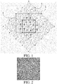
- FIG. 1 shows minimum code pattern areas that need to be obtained in a worst case in the present invention and the prior art, where the outer larger rectangle is a minimum code pattern area that needs to be obtained in the prior art, that is, 6 times the area of a unit code pattern, and the smaller rectangle in a dashed box inside the larger rectangle is a minimum code pattern area that needs to be obtained in the present invention, that is, twice the area of a unit code pattern.
- EP1936535A2 disclosed a method of decoding a first barcode and a second barcode, different from the first barcode.
- the barcodes have typically been printed on a page and are derived from image scanning.
- the first barcode comprises a plurality of marks modulated about a first grid to redundantly encode data and the second barcode comprising a plurality of marks modulated about a second grid.
- the method estimates the first grid from a bitmap representation of at least a portion of the page, using modulated marks contained therein.
- the method determines a first barcode region from the first grid, the first barcode region being a portion of the first barcode, followed by estimating a second grid from the bitmap representation, using modulated marks contained therein.
- the method determines a second barcode region from the second grid, the second barcode region being a portion of the second barcode, and then decodes the first and second barcode regions using the first and second grids respectively to derive the first and second barcodes.
- WO0126034A1 disclosed a method and a device for determining a virtual raster of a code pattern consisting of a plurality of marks with associated coordinates mn. Each mark is located at a nominal position but displaced from the nominal position in one of a plurality of directions, depending upon the value of the mark. The nominal positions form raster points gn of the virtual raster, and the raster points are situated on raster lines, which intersect at a first angle.
- a calculation device determines a second vector V2,3, which forms said angle with the first vector and is the same length as the first vector and extends from the second raster point g2 approximately to a third raster point g3.
- the mark coordinate m3 which is associated with the third raster point g3 is determined.
- the actual coordinates are calculated for the third raster point on the basis of the third mark's coordinates and its value.
- the actual coordinates for the third raster point are stored, after which the procedure is repeated taking the second vector as the starting point.
- the present application provides a decoding method in which a reading device only needs to read a relatively small code pattern area to implement decoding.
- a matrix two-dimensional code image to be decoded is a code array of jointed matrix two-dimensional code symbols, formed by multiple identical code pattern units, and area of the image is bigger than area of the unit code pattern; wherein the unit code patterns in the code array are rectangular, and code cells in the code pattern are solid points comprising positioning points located at four corners of the code pattern to define and recognize the border, and data points, i.e.
- the decoding method comprises a decoding process as follows: obtaining a binary image of a to-be-decoded code array of jointed matrix two-dimensional code symbols, locating each code point and positioning point in a unit code pattern that the code point and the positioning point belong to, so as to restore a complete unit code pattern, and then performing decoding; an image obtained by scanning does not need to include a complete unit code pattern, wherein, the locating each code point and positioning point in a unit code pattern that the code point and the positioning point belong to refers to assigning coordinate values to each code point and positioning point, where each code point and positioning point determined by the coordinate values have a same relative position relationship as each code point and positioning point in the image obtained by scanning; wherein, the assigning coordinate values to each code point and positioning point includes the following steps:
- a center point of the image is used as a rotation center.
- the parallel row lines and parallel column lines are determined by using the following steps:
- the method for restoring a two-dimensional code is described as follows: with a positioning point as a reference point, marking each code point according to a code structure feature of the two-dimensional code, and restoring a complete unit two-dimensional code according to the mark of each code point.
- the present application has the following beneficial effects:
- a method of decoding after restoring least one complete unit code pattern by locating each code point in a unit code pattern that the code point belongs to only needs an area twice the area of a unit code pattern even if decoding is performed when the code pattern is rotated by a most severe degree, while a decoding method of the prior art at least needs an area six times the area of a unit code pattern.
- a reading device does not need to read a complete unit code pattern, and decoding can be completed as long as obtained code pattern images can be combined to form a complete unit code pattern; decoding is not affected even if the obtained images are fragments belonging to different unit code patterns or the images are inclined in some degree.
- a code pattern image read by a reading device should directly include at least one complete code pattern, and therefore, a relatively large area needs to be obtained for decoding. Therefore, the decoding method of the present application significantly facilitates printing of code patterns and manufacturing of reading devices, that is, it is unnecessary to print large code patterns, and the reading devices can also be made smaller, so that the devices are easy to carry and use, and have lower costs.
- the present application is also applicable to a case in which a code pattern image is inclined, and has a smaller operation amount compared with the prior art, thereby saving resources.
- a complete unit code pattern 2 (where a unit code pattern is equivalent to a code symbol in an MPR two-dimensional code) including four positioning points 3 and multiple code points 4 in a code array 1 should be read, and then, decoding is performed. That is, in the decoding method of the prior art, four parts, indicated by A, B, C, and D, of a code pattern need to be read; moreover, the four parts need to be in a same unit code pattern, and an arrangement order of the four parts must be absolutely correct.
- the code pattern of this embodiment includes multiple code symbols of the MPR two-dimensional code.
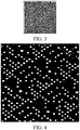
- the multiple code symbols of the MPR two-dimensional code are seamlessly jointed together, and adjacent symbols share a same positioning point (shown as a bar having marked start and end positions in the MPR code symbols, where the shape of the positioning point is a circle or a polygon), thereby forming a large-area tiled arrangement, where such an arrangement is referred to as a symbol joint.
- An example of an MPR code symbol joint diagram (that is, a code pattern printed in an MPR reading material) is shown in FIG. 2 .
- the positioning point may be replaced with a positioning line; the code also consists of multiple seamlessly-jointed unit code patterns, and can also implement the same function and be decoded by using the following method. Therefore, the positioning point in the present application also includes a module, such as a positioning line, having positioning information.
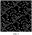
- FIG. 3 shows a schematic diagram of a code pattern image obtained in an embodiment. Due to operation during reading, the accuracy of a reading device, and the like, the obtained code pattern image is inclined and rotated by some degree as compared with FIG. 2 .
- FIG. 4 A schematic diagram of the obtained image after being enhanced is shown in FIG. 4
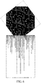
- FIG. 5 A schematic diagram of the obtained image after being binarized is shown in FIG. 5 .
- code points (bars that represent valid data information in the MPR code symbols, where the shape of the code point is a circle or a polygon) are recognized on the basis of FIG. 5 , barycenters determined and marked of each code point and positioning point are shown in FIG. 6 . The barycenters of the code point and positioning point are used in subsequent processing steps.
- the decoding method mainly includes the following steps: after binarizing the obtained image, locating each code point and positioning point in a unit code pattern that the code point and the positioning point belong to, so as to restore a complete unit code pattern, and then performing decoding.
- the locating each code point and positioning point in a unit code pattern that the code point and the positioning point belong to includes the following steps: separately determining directions of a row line and a column line where each code point is located, where the directions of the row line and column line are referred as a row direction and a column direction; separately determining a point spacing in the row direction and a point spacing in the column direction; and calibrating row coordinates of each code point by using the row direction and the point spacing in the row direction, and calibrating column coordinates of each code point and positioning point by using the column direction and the point spacing in the column direction.
- the locating each code point and positioning point in a unit code pattern that the code point and the positioning point belong to may also include the following steps: further recognizing the binarized image, so as to determine barycenters of each code point and positioning point; determining a row direction and a column direction in the image; separately drawing a group of parallel row lines and a group of parallel column lines along the row direction and the column direction to form a grid, where distances between the parallel row lines and between the parallel column lines are the point spacing in a column line direction and the point spacing in a row line direction in the code pattern respectively, and the point spacing is a distance between barycenters of adjacent code points; and calculating coordinates of each cross point in the grid, so as to assign coordinate values to each code point and positioning point in the image, where the coordinate values indicate the locations of each code point and positioning point in the unit code pattern that the code point and the positioning point belong to.
- the row direction and the column direction are preferably determined by using the following method: projecting each code point in the image of FIG. 6 to axis X, calculating the number of projections at each projection point and an average value of the numbers of projections at all projection points, and then calculating a mean square error ⁇ 0 of the numbers of projections at all the projection points; rotating the obtained image by a predetermined angle ⁇ , and calculating a mean square error ⁇ 1 according to the foregoing method; rotating the obtained image by a predetermined angle ⁇ again, and calculating a mean square error ⁇ 2 according to the foregoing method; and repeating this process until the obtained image is rotated by a total of 180°, and calculating the last mean square error ⁇ n; and taking an image state corresponding to a maximum value of ⁇ 0 to ⁇ n, and marking a direction of a line which is perpendicular to axis X and of which a projection point has a maximum number of projections in the image state as the row direction.
- the center of the image is preferably used as a rotation center during image rotation, and in this case, the image rotation sweeps a minimum area and has a minimum operation amount; however, the objective of the present application can also be implemented when another point is used as the rotation center.
- FIG. 6 to FIG. 9 are schematic diagrams of projection of the image when the image is rotated by 53°, 90°, 124° and 179° in this embodiment.
- a principle of determining the column direction is the same as the principle of determining the row direction, except that before projection and calculation of a mean square error, an image state corresponding to the row line needs to be rotated by 90° ⁇ 21°, and a maximum value of the mean square errors is taken within this range (that is, the image is rotated by 69° to 111° relative to the image state corresponding to the row line), and a direction of a line drawn perpendicular to L at a position which is on the line L and has a maximum number of projections falling thereon in the image state corresponding to the maximum value is the column direction.
- the point spacing is calculated by using the following method:
- the parallel row lines and parallel column lines are determined by using the following method:
- a grid constructing method is to separately extend the parallel row lines and parallel column lines to so that the parallel row lines and parallel column lines cross each other, thereby forming the grid.
- a method for assigning values to each code point and positioning point in the image is as follows: with a center point of the image as a reference point, calculating coordinate values of each cross point in the grid, where coordinate values of each code point in the obtained image are coordinate values of a cross point that is in the grid and closest to the code point.
- the coordinate values of the positioning point are determined according to coordinate values of four code points adjacent to the positioning point.
- the reference point may not be the center point of the image, any point on the image can be selected as the reference point, and even a point outside the image can be used as the reference point.
- a module size of the positioning point should be twice a module size of the code point.
- barycenter recognition of each code point and locating of each code point in a unit code pattern that the code point belongs to barycenter recognition and locating are also performed on the positioning point, and area information of the positioning point is marked (for example, the area information of the positioning point is recorded), so that the positioning point can be extracted as a reference point in subsequent two-dimensional code restoring.
- a specific locating method is that: coordinates of a projection of a barycenter neither fall on the row line nor fall on the column line, and a module size in a code pattern image corresponding to the barycenter is twice or more than twice a module size on the row line and the column line.
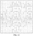
- code points at a right side of the positioning point are marked in sequence as 0, 1, 2..., 9 cyclically; code points at a left side of the positioning point are marked in sequence as 9, 8, 7..., 0 cyclically; code points at an upper side of the positioning point are marked in sequence as 0, 1, 2..., 9 cyclically; code points at a lower side of the positioning point are marked in sequence as 9, 8, 7..., 0 cyclically; and a complete unit two-dimensional code is restored according to the foregoing marks, as shown in FIG. 12 , where "+" in the figure represents the positioning point and each circle represents a code point.
- the positioning point has the following features:
- the positioning point is also marked for reference use in subsequent steps.
Claims (6)
- Verfahren zum Dekodieren eines zweidimensionalen Matrixcodes, bei dem ein zu dekodierendes zweidimensionales Matrixcodebild ein aus mehreren identischen Einheitscodemustern (2) bestehendes Code-Array zusammengefügter zweidimensionaler Matrixcodesymbole (1) ist, wobei die Fläche des zweidimensionalen Codebildes größer als die Fläche des Einheitscodemusters ist, wobei das Einheitscodemuster (2) im Code-Array (1) rechteckförmig ist und als Barcodeeinheiten mehrere massive Punkte enthält, welche in den vier Ecken des Einheitscodemusters (2) befindliche Positionierungspunkte (3)zum Definieren und Erkennen von Begrenzungen sowie Datenpunkte bzw. Codepunkte (4) umfassen, wobei die Fläche des Positionierungspunkts (3) größer als die Fläche des Codepunkts (4) ist, wobei die Einheitscodemuster (2) wiederholt angeordnet sind und nahtlos zu dem Code-Array zusammengefügter zweidimensionaler Matrixcodesymbole (1) zusammengefügt werden, indem benachbarte Einheitscodemuster (2) einen Positionierungspunkt gemeinsam benutzen, wobei das Dekodierungsverfahren den folgenden Dekodierungsprozess umfasst: Ermitteln eines Binärbilds des zu dekodierenden Code-Arrays zusammengefügter zweidimensionaler Matrixcodesymbole (1) und Bestimmen der Positionen der einzelnen Codepunkte (4) und Positionierungspunkte (3) in dem dem jeweiligen Codepunkt (4) und Positionierungspunkt (3) zugeordneten Einheitscodemuster (2), um ein vollständiges Einheitscodemuster (2) wiederherzustellen und anschließend eine Dekodierung durchzuführen, dadurch gekennzeichnet, dass ein durch Abtasten ermitteltes Bild kein einzelnes vollständiges Einheitscodemuster enthalten muss,
wobei das Bestimmen der Positionen der einzelnen Codepunkte (4) und Positionierungspunkte (3) in dem dem jeweiligen Codepunkt und Positionierungspunkt zugeordneten Einheitscodemuster (2) eine Zuweisung von Koordinatenwerten zu den einzelnen Codepunkten und Positionierungspunkten betrifft, wobei die einzelnen durch die Koordinatenwerte bestimmten Codepunkte und Positionierungspunkte die gleiche relative Positionsbeziehung wie die einzelnen Codepunkte und Positionierungspunkte in dem durch Abtasten ermittelten Bild haben;
wobei die Zuweisung von Koordinatenwerten zu den einzelnen Codepunkten und Positionierungspunkten folgende Schritte umfasst:Bestimmen der Richtungen der Zeilenlinien und Spaltenlinien, auf denen die einzelnen Codepunkte liegen, wobei die bestimmten Richtungen als Zeilenrichtung und Spaltenrichtung bezeichnet werden;Bestimmen eines Punktabstands jeweils in der Zeilenrichtung und der Spaltenrichtung; undKalibrieren der Zeilenkoordinaten der einzelnen Codepunkte und Positionierungspunkte mit Hilfe des Punktabstands in der Zeilenrichtung und einer Projektionswellenform in dieser Richtung und Kalibrieren der Spaltenkoordinaten der einzelnen Codepunkte und Positionierungspunkte mit Hilfe des Punktabstands in der Spaltenrichtung und einer Projektionswellenform in dieser Richtung; oderwobei die Zuweisung von Koordinatenwerten zu den einzelnen Codepunkten und Positionierungspunkten folgende Schritte umfasst:Bestimmen einer Zeilenrichtung und einer Spaltenrichtung in dem Bild;Zeichnen einer Gruppe von parallelen Zeilenlinien und einer Gruppe von parallelen Spaltenlinien jeweils in Abhängigkeit von der Zeilenrichtung bzw. der Spaltenrichtung, um ein Raster zu erzeugen, wobei die Abstände zwischen den parallelen Zeilenlinien und zwischen den parallelen Spaltenlinien jeweils der Punktabstand in einer Spaltenlinienrichtung und der Punktabstand in einer Zeilenlinienrichtung in dem Codemuster sind; undBerechnen der Koordinaten der einzelnen Kreuzpunkte in dem Raster, um somit den einzelnen Codepunkten und Positionierungspunkten in dem Bild Koordinatenwerte zuzuweisen;wobei das Bestimmen einer Zeilenrichtung und einer Spaltenrichtung folgende Schritte umfasst:A1. Erkennen des Binärbilds, um die Schwerpunkte der einzelnen Codepunkte und Positionierungspunkte zu bestimmen;A2. Projizieren der Schwerpunkte der einzelnen Codepunkte in dem ermittelten Bild auf eine beliebige gerade Linie L, Berechnen der Anzahl der einzelnen Projektionspunkte und eines Mittelwerts der Anzahl aller Projektionspunkte und Berechnen eines mittleren quadratischen Fehlers α0;A3. Drehen des ermittelten Bilds um einen vorbestimmten Winkel θ und Berechnen eines mittleren quadratischen Fehlers α1 nach dem Verfahren des Schritts A1;A4. Drehen des ermittelten Bilds abermals um einen vorbestimmten Winkel θ, Berechnen eines mittleren quadratischen Fehlers σ2 nach dem Verfahren des Schritts A1, und so weiter, bis das Bild insgesamt um 180° gedreht wird, und Berechnen des letzten mittleren quadratischen Fehlers σn;A5. Zeichnen einer senkrecht zu L verlaufenden Linie an einer Stelle, an der die maximale Anzahl von Projektionspunkten in einem dem Maximalwert der mittleren quadratischen Fehlerσ0 bis σn zugeordneten Bildzustand auf die Linie L fallen, wobei die gezeichnete Linie die Zeilenrichtung darstellt;A6. Drehen des der Zeilenrichtung zugeordneten Bildzustands um ±(90°±21°), Annehmen eines Maximalwerts der mittleren quadratischen Fehler in diesem Bereich und Zeichnen einer senkrecht zu L verlaufenden Linie an einer Stelle, an der die maximale Anzahl von Projektionspunkten in einem dem Maximalwert zugeordneten Bildzustand auf die Linie L fallen, wobei die gezeichnete Linie die Spaltenrichtung darstellt. - Verfahren zum Dekodieren eines zweidimensionalen Matrixcodes nach Anspruch 1, wobei der Punktabstand mit dem Autokorrelationsverfahren durch Ermitteln einer diskreten Signalperiode bestimmt wird, was durch Folgendes erfolgt:B1. Verschieben der einzelnen Codepunkte in dem dem Maximalwert der mittleren quadratischen Fehler zugeordneten Bildzustand im Schritt A5 um m Pixel entlang der Zeilenrichtung und Berechnen eines Autokorrelationskoeffizienten Z1 in Abhängigkeit von den Projektionswerten der Schwerpunkte der einzelnen Codepunkte vor und nach der Verschiebung; Verschieben der einzelnen Codepunkte in dem ermittelten Bild um m+1 Pixel und Berechnen eines Autokorrelationskoeffizienten Z2 in Abhängigkeit von den Projektionswerten der Schwerpunkte der einzelnen Codepunkte vor und nach der Verschiebung, Verschieben der einzelnen Codepunkte in dem ermittelten Bild um m+2 Pixel und Berechnen eines Autokorrelationskoeffizienten Z3 in Abhängigkeit von den Projektionswerten der Schwerpunkte der einzelnen Codepunkte vor und nach der Verschiebung, und so weiter, bis die einzelnen Codepunkte in dem ermittelten Bild um m+n Pixel verschoben werden und ein Autokorrelationskoeffizient Zn+1 errechnet wird;B2. Annehmen eines Maximalwerts aus Z1 bis Zn+1, wobei das dem Maximalwert zugeordnete Verschiebungsmaß der Codepunkte den Punktabstand e in der Zeilenrichtung darstellt; undB3. Verschieben der einzelnen Codepunkte in dem dem Maximalwert der mittleren quadratischen Fehler zugeordneten Bildzustand im Schritt A6 für n' Male entlang der Spaltenrichtung und Berechnen des maximalen Autokorrelationskoeffizienten, um den Punktabstand f in der Spaltenrichtung zu ermitteln;wobei e und f jeweils eine Pixelanzahl sind, m≥1, m eine natürliche Zahl ist und m+n≈e, m+n'≈f, m+n und m+n' jeweils eine einem vorhergesagten Punktabstand zugeordnete Pixelanzahl sind.
- Verfahren zum Dekodieren eines zweidimensionalen Matrixcodes nach Anspruch 1, wobei beim Drehen des Bilds dessen Mittelpunkt als Drehzentrum dient.
- Verfahren zum Dekodieren eines zweidimensionalen Matrixcodes nach Anspruch 1, wobei die parallelen Zeilenlinien und die parallelen Spaltenlinien durch folgende Schritte bestimmt werden:C1. Berechnen der Spitzenwerte der Schwerpunktsprojektionen der Codepunkte in den Bereichen von a·e±P entlang der Zeilenrichtung und Zeichnen der parallelen Spaltenlinien anhand der Spitzenwerte in den einzelnen Bereichen;C2. Berechnen der Spitzenwerte der Schwerpunktsprojektionen der Codepunkte in den Bereichen von a·f±P entlang der Spaltenrichtung und Zeichnen der parallelen Zeilenlinien anhand der Spitzenwerte in den einzelnen Bereichen;wobei P eine natürliche Zahl, die nicht größer als die kleinere von e und f ist, und a eine natürliche Zahl ist.
- Verfahren zum Dekodieren eines zweidimensionalen Matrixcodes nach Anspruch 1, wobei das Wiederherstellen eines vollständigen Einheitscodemusters dadurch erfolgt, dass die einzelnen Codepunkte in Abhängigkeit von den Codestrukturmerkmalen des zweidimensionalen Codes mit Bezug auf die Positionierungspunkte markiert werden und ein vollständiger zweidimensionaler Einheitscode in Abhängigkeit von den Markierungen der einzelnen Codepunkte wiederhergestellt wird.
- Verfahren zum Dekodieren eines zweidimensionalen Matrixcodes nach Anspruch 5, wobei das Wiederherstellen eines vollständigen Einheitscodemusters durch Folgendes erfolgt:Zyklisches Markieren der einzelnen Codepunkte auf der rechten oder linken Seite eines Positionierungspunkts mit Bezug auf diesen Positionierungspunkt der Reihe nach mit 0, 1, 2 bis 9;Zyklisches Markieren der einzelnen Codepunkte auf der linken oder rechten Seite des Positionierungspunkts der Reihe nach mit 9, 8, 7 bis 0;Zyklisches Markieren der einzelnen Codepunkte auf der oberen oder unteren Seite des Positionierungspunkts der Reihe nach mit 0, 1, 2 bis 9;Zyklisches Markieren der einzelnen Codepunkte auf der unteren oder oberen Seite des Positionierungspunkts der Reihe nach mit 9, 8, 7 bis 0; undWiederherstellen eines vollständigen zweidimensionalen Einheitscodes in Abhängigkeit von den obenstehenden Markierungen.
Applications Claiming Priority (2)
| Application Number | Priority Date | Filing Date | Title |
|---|---|---|---|
| CN201210145746.2A CN102708349B (zh) | 2012-05-11 | 2012-05-11 | 一种矩阵式二维码的解码方法 |
| PCT/CN2013/075517 WO2013166995A1 (zh) | 2012-05-11 | 2013-05-10 | 一种矩阵式二维码的解码方法 |
Publications (3)
| Publication Number | Publication Date |
|---|---|
| EP2849115A1 EP2849115A1 (de) | 2015-03-18 |
| EP2849115A4 EP2849115A4 (de) | 2016-01-20 |
| EP2849115B1 true EP2849115B1 (de) | 2020-07-08 |
Family
ID=46901095
Family Applications (1)
| Application Number | Title | Priority Date | Filing Date |
|---|---|---|---|
| EP13787658.7A Active EP2849115B1 (de) | 2012-05-11 | 2013-05-10 | Verfahren zur decodierung eines zweidimensionalen matrixcodes |
Country Status (8)
| Country | Link |
|---|---|
| US (1) | US9665759B2 (de) |
| EP (1) | EP2849115B1 (de) |
| JP (1) | JP5905642B2 (de) |
| KR (1) | KR101612700B1 (de) |
| CN (1) | CN102708349B (de) |
| IN (1) | IN2014MN02495A (de) |
| SG (1) | SG11201408234PA (de) |
| WO (1) | WO2013166995A1 (de) |
Families Citing this family (16)
| Publication number | Priority date | Publication date | Assignee | Title |
|---|---|---|---|---|
| CN102708349B (zh) * | 2012-05-11 | 2014-11-05 | 深圳市天朗时代科技有限公司 | 一种矩阵式二维码的解码方法 |
| CN104517089B (zh) * | 2013-09-29 | 2017-09-26 | 北大方正集团有限公司 | 一种二维码解码系统及其方法 |
| CN104700062B (zh) * | 2015-03-20 | 2017-06-27 | 中国联合网络通信集团有限公司 | 一种识别二维码的方法及设备 |
| CN104657700B (zh) * | 2015-03-25 | 2017-07-25 | 广州宽度信息技术有限公司 | 一种二维码抗损坏解码方法 |
| CN105701435A (zh) * | 2016-01-12 | 2016-06-22 | 信码互通(北京)科技有限公司 | 一种可实现自我验证的多码关联编码方法及解码方法 |
| CN105894067B (zh) * | 2016-02-06 | 2018-08-07 | 深圳市天朗时代科技有限公司 | 一种点阵二维码的编码和识读方法 |
| CN105760919B (zh) | 2016-02-06 | 2018-08-07 | 深圳市天朗时代科技有限公司 | 一种点阵二维码的编码和识别方法 |
| CN106778998A (zh) * | 2016-11-28 | 2017-05-31 | 北京慧眼智行科技有限公司 | 一种彩色二维码的生成方法和装置 |
| CN110188582B (zh) * | 2019-05-27 | 2022-08-12 | 广东石油化工学院 | 一种商品标签上隐形图形编码中定位点识别方法 |
| CN110487283B (zh) * | 2019-09-17 | 2023-04-11 | 国微集团(深圳)有限公司 | 可识别的码点块以及基于该码点块的导航方法及系统 |
| CN111220092B (zh) * | 2019-12-10 | 2021-04-23 | 东南大学 | 一种光学测量中条纹滤波器的构造方法 |
| CN111597853B (zh) * | 2020-05-26 | 2023-02-24 | 成都鹏业软件股份有限公司 | 一种混凝土标识提取方法 |
| CN111597856B (zh) * | 2020-05-26 | 2023-04-07 | 成都鹏业软件股份有限公司 | 一种基于光敏变色材料的混凝土标识提取方法 |
| DE102020130929A1 (de) * | 2020-07-31 | 2022-02-03 | Technische Universität Dortmund | Verfahren und Vorrichtung zur Auswertung von Matrixcodes |
| KR102606663B1 (ko) | 2021-04-20 | 2023-11-24 | 김종명 | 큐브의 배치 조합을 통한 콘텐츠 정보 형성 기능을 구비하는 코드 매칭 시스템 |
| CN115600619B (zh) * | 2022-12-13 | 2023-04-07 | 深圳思谋信息科技有限公司 | 点阵二维码识别方法、装置、电子设备及存储介质 |
Family Cites Families (19)
| Publication number | Priority date | Publication date | Assignee | Title |
|---|---|---|---|---|
| US6371373B1 (en) * | 1999-05-25 | 2002-04-16 | Matsushita Electric Industrial Co., Ltd. | Method for reading a two-dimensional barcode |
| SE517445C2 (sv) | 1999-10-01 | 2002-06-04 | Anoto Ab | Positionsbestämning på en yta försedd med ett positionskodningsmönster |
| EP1143372B1 (de) * | 2000-04-06 | 2006-03-22 | Seiko Epson Corporation | Verfahren und Vorrichtung zum Lesen von einem zwei-dimensionalen Strichkode und Datenspeichermedium |
| JP4013027B2 (ja) * | 2001-04-19 | 2007-11-28 | オムロン株式会社 | 2次元コード読取装置 |
| CN1294519C (zh) * | 2003-05-22 | 2007-01-10 | 武汉矽感科技有限公司 | 二维条码的编码和解码方法 |
| KR100414524B1 (ko) * | 2002-10-31 | 2004-01-16 | 주식회사 아이콘랩 | 복호 특성이 우수하며 단계별 에러레벨조정이 가능한2차원 코드 및 그 코드의 인코딩 디코딩 방법 |
| SE0203853D0 (sv) * | 2002-12-23 | 2002-12-23 | Anoto Ab | Informationskod |
| JP4364615B2 (ja) | 2003-11-28 | 2009-11-18 | 横浜ゴム株式会社 | 2次元コード表示物及び2次元コード表示タイヤ |
| CN100481117C (zh) * | 2004-03-15 | 2009-04-22 | 武汉矽感科技有限公司 | 一种二维条码编解码方法 |
| JP2007172304A (ja) * | 2005-12-22 | 2007-07-05 | Sony Corp | 2次元バーコード、情報処理装置、情報処理方法、並びにプログラム |
| CN1885311A (zh) * | 2006-05-29 | 2006-12-27 | 深圳矽感科技有限公司 | 二维码及其编解码方法 |
| JP2007323498A (ja) * | 2006-06-02 | 2007-12-13 | Daido Steel Co Ltd | 情報コード表示シート |
| CN100511271C (zh) | 2006-11-16 | 2009-07-08 | 深圳市天朗时代科技有限公司 | 二维码解码方法 |
| AU2006252254B2 (en) | 2006-12-22 | 2009-03-05 | Canon Kabushiki Kaisha | Multiple barcode detection |
| EP2248068B1 (de) | 2008-01-29 | 2014-04-30 | Veritec, Inc. | Zweidimensionales symbol und verfahren, um es zu lesen |
| CN101587556B (zh) * | 2009-04-08 | 2011-06-01 | 广东威创视讯科技股份有限公司 | 一种二维条码识别方法 |
| CN101710385B (zh) * | 2009-12-28 | 2013-05-29 | 天津优尼莱博泰克电子科技发展有限公司 | 高性能二维条形码解码方法 |
| CN101882210B (zh) | 2010-06-01 | 2012-06-27 | 福建新大陆电脑股份有限公司 | 矩阵式二维条码解码芯片及其解码方法 |
| CN102708349B (zh) | 2012-05-11 | 2014-11-05 | 深圳市天朗时代科技有限公司 | 一种矩阵式二维码的解码方法 |
-
2012
- 2012-05-11 CN CN201210145746.2A patent/CN102708349B/zh active Active
-
2013
- 2013-05-10 WO PCT/CN2013/075517 patent/WO2013166995A1/zh active Application Filing
- 2013-05-10 US US14/400,460 patent/US9665759B2/en active Active
- 2013-05-10 KR KR1020147034638A patent/KR101612700B1/ko active IP Right Grant
- 2013-05-10 JP JP2015510632A patent/JP5905642B2/ja active Active
- 2013-05-10 EP EP13787658.7A patent/EP2849115B1/de active Active
- 2013-05-10 IN IN2495MUN2014 patent/IN2014MN02495A/en unknown
- 2013-05-10 SG SG11201408234PA patent/SG11201408234PA/en unknown
Non-Patent Citations (1)
| Title |
|---|
| None * |
Also Published As
| Publication number | Publication date |
|---|---|
| US9665759B2 (en) | 2017-05-30 |
| US20150129658A1 (en) | 2015-05-14 |
| KR101612700B1 (ko) | 2016-04-15 |
| CN102708349B (zh) | 2014-11-05 |
| EP2849115A4 (de) | 2016-01-20 |
| KR20150044848A (ko) | 2015-04-27 |
| JP5905642B2 (ja) | 2016-04-20 |
| IN2014MN02495A (de) | 2015-07-17 |
| EP2849115A1 (de) | 2015-03-18 |
| WO2013166995A1 (zh) | 2013-11-14 |
| JP2015522861A (ja) | 2015-08-06 |
| CN102708349A (zh) | 2012-10-03 |
| SG11201408234PA (en) | 2015-01-29 |
Similar Documents
| Publication | Publication Date | Title |
|---|---|---|
| EP2849115B1 (de) | Verfahren zur decodierung eines zweidimensionalen matrixcodes | |
| EP3413240B1 (de) | Verfahren zur codierung und identifizierung eines 2d-bitmap-barcodes | |
| WO2017133532A1 (zh) | 一种点阵二维码的编码和识读方法 | |
| JP4294025B2 (ja) | インターフェース表面を生成する方法、および符号化データを読み取る方法 | |
| US10679175B2 (en) | Two-dimensional code, system for creation of two-dimensional code, and analysis program | |
| CN108334922B (zh) | 点阵二维码及点阵二维码的编码和识别方法 | |
| CN105989317B (zh) | 一种二维码的识别方法及装置 | |
| EP3309704B1 (de) | Zweidimensionales codepartitionierungs- und -decodierungsverfahren und -system | |
| US8550351B2 (en) | Matrix type two-dimensional barcode decoding chip and decoding method thereof | |
| CN1641683B (zh) | 通过m阵列解码和快速图像匹配的笔划定位 | |
| US9734443B2 (en) | Two-dimensional code, two-dimensional-code analysis system, and two-dimensional-code generation system | |
| JP2005267598A (ja) | 二次元バーコード及びその符号復号化方法 | |
| CN104346640A (zh) | 二维码及生成二维码的方法 | |
| WO2004084125A1 (ja) | ドットパターンを用いた情報入出力方法 | |
| JP2005267598A5 (de) | ||
| EP3561729B1 (de) | Verfahren zur detektion und erfassung von hochdichten visuellen markern mit grosser reichweite | |
| WO2018210077A1 (zh) | 标识码的生成方法及装置 | |
| CN103473518B (zh) | 运单信息录入和黑白色块编码解码系统 | |
| JP5184672B2 (ja) | 二次元コードの読取方法およびプログラム | |
| EP1269396B1 (de) | Vorrichtungen und verfahren, die bilder betreffen | |
| JP2012094083A (ja) | 読み取り装置、投票券払い戻し装置、投票券発行装置、および読み取り方法 | |
| CN109978106A (zh) | 点阵编码基底及点阵编码识别方法 | |
| CN113297872B (zh) | 一种Dotcode识别方法、设备 | |
| CN102955927B (zh) | 光学辨识器的二维信息编码区域的定义方法 | |
| JP2009181346A (ja) | 画像処理装置、ペン・デバイスおよびプログラム |
Legal Events
| Date | Code | Title | Description |
|---|---|---|---|
| PUAI | Public reference made under article 153(3) epc to a published international application that has entered the european phase |
Free format text: ORIGINAL CODE: 0009012 |
|
| 17P | Request for examination filed |
Effective date: 20141204 |
|
| AK | Designated contracting states |
Kind code of ref document: A1 Designated state(s): AL AT BE BG CH CY CZ DE DK EE ES FI FR GB GR HR HU IE IS IT LI LT LU LV MC MK MT NL NO PL PT RO RS SE SI SK SM TR |
|
| AX | Request for extension of the european patent |
Extension state: BA ME |
|
| DAX | Request for extension of the european patent (deleted) | ||
| RA4 | Supplementary search report drawn up and despatched (corrected) |
Effective date: 20151217 |
|
| RIC1 | Information provided on ipc code assigned before grant |
Ipc: G06K 7/14 20060101ALI20151211BHEP Ipc: G06K 7/10 20060101AFI20151211BHEP |
|
| STAA | Information on the status of an ep patent application or granted ep patent |
Free format text: STATUS: EXAMINATION IS IN PROGRESS |
|
| 17Q | First examination report despatched |
Effective date: 20181001 |
|
| GRAP | Despatch of communication of intention to grant a patent |
Free format text: ORIGINAL CODE: EPIDOSNIGR1 |
|
| STAA | Information on the status of an ep patent application or granted ep patent |
Free format text: STATUS: GRANT OF PATENT IS INTENDED |
|
| INTG | Intention to grant announced |
Effective date: 20200131 |
|
| RIN1 | Information on inventor provided before grant (corrected) |
Inventor name: CHANG, ZHIGUO Inventor name: LV, YINGFENG Inventor name: LI, ZHENGFANG |
|
| GRAS | Grant fee paid |
Free format text: ORIGINAL CODE: EPIDOSNIGR3 |
|
| GRAA | (expected) grant |
Free format text: ORIGINAL CODE: 0009210 |
|
| STAA | Information on the status of an ep patent application or granted ep patent |
Free format text: STATUS: THE PATENT HAS BEEN GRANTED |
|
| AK | Designated contracting states |
Kind code of ref document: B1 Designated state(s): AL AT BE BG CH CY CZ DE DK EE ES FI FR GB GR HR HU IE IS IT LI LT LU LV MC MK MT NL NO PL PT RO RS SE SI SK SM TR |
|
| REG | Reference to a national code |
Ref country code: GB Ref legal event code: FG4D |
|
| REG | Reference to a national code |
Ref country code: CH Ref legal event code: EP Ref country code: AT Ref legal event code: REF Ref document number: 1289245 Country of ref document: AT Kind code of ref document: T Effective date: 20200715 |
|
| REG | Reference to a national code |
Ref country code: DE Ref legal event code: R096 Ref document number: 602013070535 Country of ref document: DE |
|
| REG | Reference to a national code |
Ref country code: IE Ref legal event code: FG4D |
|
| REG | Reference to a national code |
Ref country code: CH Ref legal event code: NV Representative=s name: DENNEMEYER AG, CH |
|
| REG | Reference to a national code |
Ref country code: NL Ref legal event code: FP |
|
| REG | Reference to a national code |
Ref country code: LT Ref legal event code: MG4D |
|
| REG | Reference to a national code |
Ref country code: AT Ref legal event code: MK05 Ref document number: 1289245 Country of ref document: AT Kind code of ref document: T Effective date: 20200708 |
|
| PG25 | Lapsed in a contracting state [announced via postgrant information from national office to epo] |
Ref country code: ES Free format text: LAPSE BECAUSE OF FAILURE TO SUBMIT A TRANSLATION OF THE DESCRIPTION OR TO PAY THE FEE WITHIN THE PRESCRIBED TIME-LIMIT Effective date: 20200708 Ref country code: GR Free format text: LAPSE BECAUSE OF FAILURE TO SUBMIT A TRANSLATION OF THE DESCRIPTION OR TO PAY THE FEE WITHIN THE PRESCRIBED TIME-LIMIT Effective date: 20201009 Ref country code: NO Free format text: LAPSE BECAUSE OF FAILURE TO SUBMIT A TRANSLATION OF THE DESCRIPTION OR TO PAY THE FEE WITHIN THE PRESCRIBED TIME-LIMIT Effective date: 20201008 Ref country code: AT Free format text: LAPSE BECAUSE OF FAILURE TO SUBMIT A TRANSLATION OF THE DESCRIPTION OR TO PAY THE FEE WITHIN THE PRESCRIBED TIME-LIMIT Effective date: 20200708 Ref country code: BG Free format text: LAPSE BECAUSE OF FAILURE TO SUBMIT A TRANSLATION OF THE DESCRIPTION OR TO PAY THE FEE WITHIN THE PRESCRIBED TIME-LIMIT Effective date: 20201008 Ref country code: PT Free format text: LAPSE BECAUSE OF FAILURE TO SUBMIT A TRANSLATION OF THE DESCRIPTION OR TO PAY THE FEE WITHIN THE PRESCRIBED TIME-LIMIT Effective date: 20201109 Ref country code: FI Free format text: LAPSE BECAUSE OF FAILURE TO SUBMIT A TRANSLATION OF THE DESCRIPTION OR TO PAY THE FEE WITHIN THE PRESCRIBED TIME-LIMIT Effective date: 20200708 Ref country code: LT Free format text: LAPSE BECAUSE OF FAILURE TO SUBMIT A TRANSLATION OF THE DESCRIPTION OR TO PAY THE FEE WITHIN THE PRESCRIBED TIME-LIMIT Effective date: 20200708 Ref country code: HR Free format text: LAPSE BECAUSE OF FAILURE TO SUBMIT A TRANSLATION OF THE DESCRIPTION OR TO PAY THE FEE WITHIN THE PRESCRIBED TIME-LIMIT Effective date: 20200708 Ref country code: SE Free format text: LAPSE BECAUSE OF FAILURE TO SUBMIT A TRANSLATION OF THE DESCRIPTION OR TO PAY THE FEE WITHIN THE PRESCRIBED TIME-LIMIT Effective date: 20200708 |
|
| PG25 | Lapsed in a contracting state [announced via postgrant information from national office to epo] |
Ref country code: LV Free format text: LAPSE BECAUSE OF FAILURE TO SUBMIT A TRANSLATION OF THE DESCRIPTION OR TO PAY THE FEE WITHIN THE PRESCRIBED TIME-LIMIT Effective date: 20200708 Ref country code: RS Free format text: LAPSE BECAUSE OF FAILURE TO SUBMIT A TRANSLATION OF THE DESCRIPTION OR TO PAY THE FEE WITHIN THE PRESCRIBED TIME-LIMIT Effective date: 20200708 Ref country code: PL Free format text: LAPSE BECAUSE OF FAILURE TO SUBMIT A TRANSLATION OF THE DESCRIPTION OR TO PAY THE FEE WITHIN THE PRESCRIBED TIME-LIMIT Effective date: 20200708 Ref country code: IS Free format text: LAPSE BECAUSE OF FAILURE TO SUBMIT A TRANSLATION OF THE DESCRIPTION OR TO PAY THE FEE WITHIN THE PRESCRIBED TIME-LIMIT Effective date: 20201108 |
|
| REG | Reference to a national code |
Ref country code: DE Ref legal event code: R097 Ref document number: 602013070535 Country of ref document: DE |
|
| PG25 | Lapsed in a contracting state [announced via postgrant information from national office to epo] |
Ref country code: SM Free format text: LAPSE BECAUSE OF FAILURE TO SUBMIT A TRANSLATION OF THE DESCRIPTION OR TO PAY THE FEE WITHIN THE PRESCRIBED TIME-LIMIT Effective date: 20200708 Ref country code: RO Free format text: LAPSE BECAUSE OF FAILURE TO SUBMIT A TRANSLATION OF THE DESCRIPTION OR TO PAY THE FEE WITHIN THE PRESCRIBED TIME-LIMIT Effective date: 20200708 Ref country code: DK Free format text: LAPSE BECAUSE OF FAILURE TO SUBMIT A TRANSLATION OF THE DESCRIPTION OR TO PAY THE FEE WITHIN THE PRESCRIBED TIME-LIMIT Effective date: 20200708 Ref country code: CZ Free format text: LAPSE BECAUSE OF FAILURE TO SUBMIT A TRANSLATION OF THE DESCRIPTION OR TO PAY THE FEE WITHIN THE PRESCRIBED TIME-LIMIT Effective date: 20200708 Ref country code: EE Free format text: LAPSE BECAUSE OF FAILURE TO SUBMIT A TRANSLATION OF THE DESCRIPTION OR TO PAY THE FEE WITHIN THE PRESCRIBED TIME-LIMIT Effective date: 20200708 Ref country code: IT Free format text: LAPSE BECAUSE OF FAILURE TO SUBMIT A TRANSLATION OF THE DESCRIPTION OR TO PAY THE FEE WITHIN THE PRESCRIBED TIME-LIMIT Effective date: 20200708 |
|
| PLBE | No opposition filed within time limit |
Free format text: ORIGINAL CODE: 0009261 |
|
| STAA | Information on the status of an ep patent application or granted ep patent |
Free format text: STATUS: NO OPPOSITION FILED WITHIN TIME LIMIT |
|
| PG25 | Lapsed in a contracting state [announced via postgrant information from national office to epo] |
Ref country code: AL Free format text: LAPSE BECAUSE OF FAILURE TO SUBMIT A TRANSLATION OF THE DESCRIPTION OR TO PAY THE FEE WITHIN THE PRESCRIBED TIME-LIMIT Effective date: 20200708 |
|
| 26N | No opposition filed |
Effective date: 20210409 |
|
| PG25 | Lapsed in a contracting state [announced via postgrant information from national office to epo] |
Ref country code: SK Free format text: LAPSE BECAUSE OF FAILURE TO SUBMIT A TRANSLATION OF THE DESCRIPTION OR TO PAY THE FEE WITHIN THE PRESCRIBED TIME-LIMIT Effective date: 20200708 |
|
| PG25 | Lapsed in a contracting state [announced via postgrant information from national office to epo] |
Ref country code: SI Free format text: LAPSE BECAUSE OF FAILURE TO SUBMIT A TRANSLATION OF THE DESCRIPTION OR TO PAY THE FEE WITHIN THE PRESCRIBED TIME-LIMIT Effective date: 20200708 |
|
| PG25 | Lapsed in a contracting state [announced via postgrant information from national office to epo] |
Ref country code: LU Free format text: LAPSE BECAUSE OF NON-PAYMENT OF DUE FEES Effective date: 20210510 Ref country code: MC Free format text: LAPSE BECAUSE OF FAILURE TO SUBMIT A TRANSLATION OF THE DESCRIPTION OR TO PAY THE FEE WITHIN THE PRESCRIBED TIME-LIMIT Effective date: 20200708 |
|
| REG | Reference to a national code |
Ref country code: BE Ref legal event code: MM Effective date: 20210531 |
|
| PG25 | Lapsed in a contracting state [announced via postgrant information from national office to epo] |
Ref country code: IE Free format text: LAPSE BECAUSE OF NON-PAYMENT OF DUE FEES Effective date: 20210510 |
|
| PG25 | Lapsed in a contracting state [announced via postgrant information from national office to epo] |
Ref country code: BE Free format text: LAPSE BECAUSE OF NON-PAYMENT OF DUE FEES Effective date: 20210531 |
|
| PG25 | Lapsed in a contracting state [announced via postgrant information from national office to epo] |
Ref country code: HU Free format text: LAPSE BECAUSE OF FAILURE TO SUBMIT A TRANSLATION OF THE DESCRIPTION OR TO PAY THE FEE WITHIN THE PRESCRIBED TIME-LIMIT; INVALID AB INITIO Effective date: 20130510 |
|
| PG25 | Lapsed in a contracting state [announced via postgrant information from national office to epo] |
Ref country code: CY Free format text: LAPSE BECAUSE OF FAILURE TO SUBMIT A TRANSLATION OF THE DESCRIPTION OR TO PAY THE FEE WITHIN THE PRESCRIBED TIME-LIMIT Effective date: 20200708 |
|
| PGFP | Annual fee paid to national office [announced via postgrant information from national office to epo] |
Ref country code: NL Payment date: 20230519 Year of fee payment: 11 Ref country code: FR Payment date: 20230526 Year of fee payment: 11 Ref country code: DE Payment date: 20230519 Year of fee payment: 11 Ref country code: CH Payment date: 20230602 Year of fee payment: 11 |
|
| PGFP | Annual fee paid to national office [announced via postgrant information from national office to epo] |
Ref country code: GB Payment date: 20230524 Year of fee payment: 11 |