EP2848778A1 - Verfahren zur Umwandlung von geothermischer Energie - Google Patents
Verfahren zur Umwandlung von geothermischer Energie Download PDFInfo
- Publication number
- EP2848778A1 EP2848778A1 EP13004458.9A EP13004458A EP2848778A1 EP 2848778 A1 EP2848778 A1 EP 2848778A1 EP 13004458 A EP13004458 A EP 13004458A EP 2848778 A1 EP2848778 A1 EP 2848778A1
- Authority
- EP
- European Patent Office
- Prior art keywords
- energy
- probe
- refrigerant
- geothermal
- heat
- Prior art date
- Legal status (The legal status is an assumption and is not a legal conclusion. Google has not performed a legal analysis and makes no representation as to the accuracy of the status listed.)
- Granted
Links
Images

Classifications
-
- F—MECHANICAL ENGINEERING; LIGHTING; HEATING; WEAPONS; BLASTING
- F01—MACHINES OR ENGINES IN GENERAL; ENGINE PLANTS IN GENERAL; STEAM ENGINES
- F01K—STEAM ENGINE PLANTS; STEAM ACCUMULATORS; ENGINE PLANTS NOT OTHERWISE PROVIDED FOR; ENGINES USING SPECIAL WORKING FLUIDS OR CYCLES
- F01K25/00—Plants or engines characterised by use of special working fluids, not otherwise provided for; Plants operating in closed cycles and not otherwise provided for
- F01K25/08—Plants or engines characterised by use of special working fluids, not otherwise provided for; Plants operating in closed cycles and not otherwise provided for using special vapours
- F01K25/10—Plants or engines characterised by use of special working fluids, not otherwise provided for; Plants operating in closed cycles and not otherwise provided for using special vapours the vapours being cold, e.g. ammonia, carbon dioxide, ether
- F01K25/106—Ammonia
Definitions
- the invention relates to a method for the conversion of geothermal energy, wherein with a geothermal probe, which is introduced in the upper soil to a depth of about 50 m, d. H. does not require deep drilling, thermal energy is transferred from the ground to a liquid medium, this energy is transferred from the liquid medium to a liquid heat transfer medium, this energy is transferred from the liquid heat transfer medium to a refrigerant in countercurrent, whereby the refrigerant is converted into a gaseous state, Subsequently, the energy of the refrigerant is converted into a rotational movement and the energy of the rotational movement is converted by a generator into electrical energy.
- This described geothermal probe consists in particular of a main probe, which at least one evaporator chamber, a heat exchanger chamber, which consists of at least one heat medium chamber of the countercurrent evaporator and is arranged in an open main probe heat medium circuit of a heating means has.
- This geothermal probe also has a feeder probe with an outer sheath, which is enclosed on its outer side from the ground, a probe gap, which is at least partially bounded by the inner side of the outer sheath and the probe bottom, in which the main probe is arranged, and an inlet for the liquid warming agents.
- the object of the invention is to provide a method which operates in continuous operation and with a geothermal probe, which works effectively and safely with a small probe depth, in particular with a maximum probe depth of about 50 m.
- the object of the invention is achieved by a method having the features according to claim 1.
- Essential to the invention is that the method is continuously operable, the energy of the refrigerant in a gas pressure motor is converted into a rotational movement, wherein the gaseous refrigerant continuously applied to the gas pressure motor, the generator is an alternator, at least the refrigerant is guided in a closed circuit and the refrigerant Ammonia is.
- the selection, dimensioning and arrangement of the process-essential system components according to the invention was carried out in order in particular to ensure a process which can be operated continuously under practical conditions.
- An essential criterion of the selection was to have the possibility, by a conventional process control all process-essential plant components and their To be able to coordinate process parameters to one another in order to ensure continuous process management.
- the inventive selection or combination of a gas-pressure engine as a turbomachine and the refrigerant ammonia was the result of many years of research and extensive testing.
- a geothermal probe is sunk in a conventional manner from the earth's surface into a borehole, has an upper end to be arranged in the region of the earth's surface and a lower end to be sunk into the borehole.
- the geothermal probe is one which, at least consisting of a main probe, which comprises at least: an evaporator chamber, which consists of at least one refrigerant chamber of a countercurrent evaporator and a closed refrigerant circuit is arranged, a riser, which with the lower End of the evaporator space is connected to a supply line, which is connected to the evaporator space and is arranged in the refrigerant circuit, a heat exchanger chamber, which consists of at least one heat medium chamber of the counterflow evaporator and is arranged in a main probe heat medium cycle of a heating means, and a feeder probe, which comprises at least: an outer sheath, which is enclosed on its outer side from the ground, a probe gap which is at least partially bounded by the inner side of the outer sheath and a probe bottom, in which the main probe is arranged, andi an inlet, for the liquid heating means, which is arranged in at least one open feeder-probe-heating-medium
- the geothermal probe has a measuring and control device which is integrated into the process control for providing a continuous gaseous refrigerant flow.
- the process measurement data obtained in the usual manner for example temperature and pressure data determined by temperature and pressure measuring devices, are used by the measuring and control device, in particular, for at least the circuits: refrigerant cycle main probe heat medium cycle and feed probe heat medium cycle to match the type of one another, that via the riser, coming from the evaporator chamber, a constant as possible media flow is applied.
- This constant flow of media is in particular a necessary condition to use the geothermal probe as part of a continuously operable geothermal recovery plant for generating mechanical energy, this system has at least one gas pressure motor as a turbomachine.
- the object of the invention is also achieved by a plant for the conversion of geothermal energy with the features of claim 5.
- the geothermal probe is arranged in the ground up to a maximum depth of 50 m, in particular up to 42 m.
- the main probe 1 of the geothermal probe is filled with about 3,000 liters of Antifrogen, wherein the hole (Teufe), in which the geothermal probe is introduced in the usual way, about 42 m deep.
- the Antifrogen serves as antifreeze to avoid the freezing of the water in the geothermal probe.
- the main probe 1 can be equipped with a thermal insulation 1.a on the first ten depth meters, as viewed from the earth's surface.
- the Antifrogen filled main probe 1 is a connecting pipe, 2.5 cm internal diameter, 40m length, with integrated counterflow evaporators 1.2; 1.2.1; 1.2.2, with a total length of 3 x 3.40 m (total 10,20m) and a power of up to 30 KW, and can be anchored in at least three places and at the bottom of the probe.
- the countercurrent evaporator 1.2; 1.2.1; 1.2.2 are to be arranged in the lower half of the main probe 1.
- the divided into two chambers a / b countercurrent evaporator 1.2; 1.2.1; 1.2.2 are on one side the chamber a with the coolant ammonia (NH 3 ) with a temperature of about -10 ° C, and on the other side the chamber b with an antifreeze with a temperature of about + 4 ° C. - + 7 ° C filled.
- NH 3 coolant ammonia
- coolant eg CO 2 , propane, butane, etc.
- NH 3 a replacement for NH 3
- the evaporation begins in the first series-connected countercurrent evaporator 1.2 and forms wet steam. This wet steam is again evaporated in the second countercurrent evaporator 1.2.1 and transferred to the third countercurrent evaporator 1.2.2 for the last evaporation.
- the amount of ammonia gas produced by evaporation after the last evaporation is (+/-) 40 m 3 / h and is available as saturated steam.
- ammonia gas After exiting the soil, the ammonia gas is passed through an expansion valve 1.3 in a countercurrent superheater 1.4 for further drying and is now available as
- the pumped dry gas is then passed through a flow meter 1.4.1 in a reciprocating compressor 1.5 with a power of 75 KW and compressed to the desired pressure. After compression, the gas passes through the desuperheater and the condenser, designed as a countercurrent exchanger, in a pressure vessel as NH 3 separator and is ready for the removal of energy.
- the ammonia contained in chamber b is again designed after evaporation in the pressure vessel in the desuperheater and the condenser as a countercurrent exchanger, recycled, the building's own boiler for supply provided with heat
- the liquid ammonia is returned to the total circulation via the desuperheater 1.7, designed as a countercurrent exchanger.
- the liquid ammonia passes, after the intermediate flow meter 1.4.1, again via the countercurrent superheater 1.4 in the subcooler 1.9, which lowers the temperature to about 20 ° C.
- the ammonia from the subcooler 1.9 is now directed to support and for continuous circulation and heating of the Antifrogen in the main probe 1 and then as reflux back into the subcooler 1.9 and from there into a refrigerant collector with oil separator 2 and the solenoid valve 2.1 in a countercurrent evaporator. 3 transferred with a power of 50 KW.
- a cold customer such as an air conditioner or other cooling device, with temperatures of approx. 3 - 7 ° C, to be supplied.
- the return from the chiller is again passed through the heat exchanger P1 and the main probe 1, as described above, supplied before it is transferred via the solenoid valve 2.1 and the refrigerant collector with oil separator 2 in two countercurrent pre-evaporator 3.
- the countercurrent pre-evaporator 3 vaporizes the liquid ammonia, via a valve, the ammonia is again through the inner tube 1.1 in the main probe 1 the countercurrent evaporators 1.2; 1.2.1; 1.2.2 is supplied. The whole process starts from the beginning.
- the two types of use, heat supply and electricity generation, can be used in parallel and / or supplementary as well as interchangeable.
- the gas pressure motor M used according to the invention has, for example, the following technical data: Type: Rotary piston gas pressure motor ⁇ 50 KW electrical power Quantity Consumption: about 120 m 3 per hour at about 35 KW electrical power
- the gas flows from a pressure vessel into the gas pressure motor at a temperature of ⁇ 15 ° C and at a pressure of ⁇ 4 bar. Power requirements: 651 cm 3 per revolution (RPM)
- a suitable generator Via a magnetic coupling on the gas pressure motor, a suitable generator is driven, which emits an electric power of up to ⁇ 35 KW to the feed point with a mains supply device.
- the amount of gas must be increased accordingly, which is partially solved with the geothermal probe used in the invention.
- a second geothermal probe can be set to increase the amount of gas delivered.
- the hot gas After the compressor, the hot gas, up to about 130 ° C, flows through an oil separator and a three-way valve into the gas engine. In the gas pressure motor, a pressure conversion of max. 15 bar to 3-4 bar. while the dry gas condenses. The resulting energy is delivered to a generator G, which feeds the energy into a conventional consumer.
- the condensed NH 3 returns to the NH 3 separator.
- the NH 3 trimmer has a standard operating pressure of 16 bar, a capacity of 0.2 m 3 and a power of 70 KW at a condensation temperature of 45 ° C.
- the dimension and design of the separator depends on the corresponding refrigeration requirements.
- the gas now flows via connecting lines in the pre-evaporator and valves in the Geoverdampfer, which are formed in the geothermal probe as a tube exchanger, and continues to evaporate there.
- the evaporators are installed in series and are controlled separately as needed, each with a specific KW power is designed.
- the system provides a total output of 75KW heat with this construction - a quadrupling of the previous performance.
- the effectiveness of the system according to the invention is guaranteed by the fact that a continuous geothermal energy source is available and with the support of heat exchangers a higher demand can be secured.
- a continuous geothermal energy source is available and with the support of heat exchangers a higher demand can be secured.
- heat output and cooling capacity can be provided.
Landscapes
- Engineering & Computer Science (AREA)
- Chemical & Material Sciences (AREA)
- Combustion & Propulsion (AREA)
- Mechanical Engineering (AREA)
- General Engineering & Computer Science (AREA)
- Engine Equipment That Uses Special Cycles (AREA)
Abstract
Description
- Die Erfindung betrifft ein Verfahren zur Umwandlung von geothermischer Energie, wobei mit einer Erdwärmesonde, welche im oberen Erdreich bis zu einer Tiefe von ca. 50 m eingebracht ist, d. h. keine Tiefenbohrung erfordert, vom Erdreich Wärmeenergie auf ein flüssiges Medium übertragen wird, diese Energie vom flüssigen Medium auf ein flüssiges Wärmeträgermittel übertragen wird, diese Energie vom flüssigen Wärmeträgermittel auf ein Kälteträgermittel im Gegenstrom übertragen wird, wobei dabei das Kälteträgermittel in einen gasförmigen Zustand überführt wird, nachfolgend die Energie des Kälteträgermittels in eine Rotationsbewegung umgewandelt und die Energie der Rotationsbewegung mit einem Generator in elektrische Energie umgewandelt wird.
- Aus der
DE 20 2012 003 480.4 ist eine solche Erdwärmesonde und Erdwärme-Gewinnungsanlage bekannt, wobei diese Anlage eine Strömungsmaschine besitzt. Zur Art und Dimensionierung der möglicherweise einzusetzenden Strömungsmaschine werden dort keine Angaben gemacht.
Diese beschriebene Erdwärmesonde besteht insbesondere aus einer Hauptsonde, welche zumindest einen Verdampferraum, einem Wärmetauscherraum, welcher aus zumindest einer Wärmemittel-Kammer des Gegenstromverdampfers besteht und in einem offenen Hauptsonden-Wärmemittel-Kreislauf eines Wärmemittels angeordnet ist, besitzt. Diese Erdwärmesonde besitzt außerdem eine Zubringersonde mit einem Außenmantel, welcher an seiner äußeren Seite vom Erdreich umschlossen ist, einen Sondenzwischenraum, welcher zumindest teilweise durch die innere Seite des Außenmantels und dem Sondenboden begrenzt wird, in welchem die Hauptsonde angeordnet ist, und einen Zulauf für das flüssige Wärmemittel. - Es besteht derzeit, zumindest in Deutschland, ein dringender Bedarf nach Erzeugungsanlagen für elektrischen Strom, welche kontinuierlich, d. h. als Grundlastkraftwerke betrieben werden können. Dabei werden diesbezügliche insbesondere technische Lösungen bezüglich Verfahren zur Verstromung von geothermischer Energie gesucht, wobei die Stromerzeugung auch autark betreibbar sein sollte. Die geothermischer Energie soll unter Verwendung von Erdwärmesonden erfolgen, welche keine Tiefenbohrungen erfordern, sondern mit Bohrtiefen von ca. 50 m auskommen. Dabei stehen Erzeugungsanlagen für elektrischen Strom mit einer Leistung von ca. 75 KW im besonderen Fokus.
- Aufgabe der Erfindung ist es, ein Verfahren bereitzustellen, welches im kontinuierlichen Betrieb und mit einer Erdwärmesonde arbeitet, welche effektiv und sicher mit einer geringen Sondentiefe, insbesondere mit einer maximalen Sondentiefe von ca. 50 m, arbeitet.
- Die Aufgabe der Erfindung wird durch ein Verfahren mit den Merkmalen gemäß Anspruch 1 gelöst.
- Erfindungswesentlich ist, dass das Verfahren kontinuierlich betreibbar ist, die Energie des Kälteträgermittels in einem Gasdruckmotor in eine Rotationsbewegung umgesetzt wird, wobei das gasförmige Kältemittel kontinuierlich am Gasdruckmotor anliegt, der Generator ein Wechselstromgenerator ist, zumindest das Kälteträgermittel in einem geschlossenen Kreislauf geführt wird und das Kälteträgermittel Ammoniak ist.
- Die erfindungsgemäße Auswahl, Dimensionierung und Anordnung der verfahrenswesentlichen Anlagenkomponenten erfolgte um insbesondere ein unter Praxisbedingungen kontinuierlich betreibbares Verfahren zu sichern. Ein wesentliches Kriterium der Auswahl dabei war, die Möglichkeit zu besitzen, durch eine übliche Prozesssteuerung alle verfahrenswesentlichen Anlagenkomponenten und deren Prozessparameter aufeinander abstimmen zu können, um eine kontinuierliche Prozessführung zu sichern.
Die erfindungsgemäße Auswahl bzw. Kombination von einem Gasdruckmotor als Strömungsmaschine und dem Kälteträgermittel Ammoniak war das Ergebnis langjähriger Untersuchungen und umfänglicher Erprobungen. - Eine Erdwärmesonde ist in üblicher Art und Weise von der Erdoberfläche aus in ein Bohrloch versenkbar, besitzt ein im Bereich der Erdoberfläche anzuordnendes oberes Ende und ein in das Bohrloch zu versenkendes unteres Ende.
- Die abhängigen Ansprüche 2 bis 4 enthalten vorteilhafte Ausgestaltungen der Erfindung ohne diese damit zu begrenzen.
- Bevorzugt ist, dass die Erdwärmesonde eine solche ist, welche zumindest bestehend aus einer Hauptsonde, welche zumindest umfasst: einen Verdampferraum, welcher aus zumindest einer Kältemittel-Kammer eines Gegenstromverdampfers besteht und einem geschlossenen Kältemittel-Kreislauf angeordnet ist, einer Steigleitung, welche mit dem unteren Ende des Verdampferraums verbunden ist, einer Zuleitung, welche mit dem Verdampferraum verbunden ist und im Kältemittel-Kreislauf angeordnet ist, einem Wärmetauscherraum, welcher aus zumindest einer Wärmemittel-Kammer des Gegenstromverdampfers besteht und in einem Hauptsonden-Wärmemittel-Kreislauf eines Wärmemittels angeordnet ist, und einer Zubringersonde, welche zumindest umfasst: einen Außenmantel, welcher an seiner äußeren Seite vom Erdreich umschlossen ist, einem Sondenzwischenraum, welcher zumindest teilweise durch die innere Seite des Außenmantels und einem Sondenboden begrenzt wird, in welchem die Hauptsonde angeordnet ist, und zumindest einem Zulauf, für das flüssige Wärmemittel, welcher in zumindest einem offenen Zubringersonden-Wärmemittel-Kreislauf eines Wärmemittels angeordnet ist,
Eine solche Erdwärmesonde und deren Funktionsweise ist in derDE 20 2012 003 480.4 beschrieben. - Bevorzugt ist weiterhin, dass die Erdwärmesonde eine Mess- und Regeleinrichtung besitzt, welche in die Prozesssteuerung zur Bereitstellung eines kontinuierlichen gasförmigen Kältemittelstromes integriert ist.
- Die in üblicher Art und Weise gewonnenen Prozessmessdaten, beispielsweise durch Temperatur- und Druckmesseinrichtungen ermittelte Temperatur und Druckangaben, werden durch die Mess- und Regeleinrichtung insbesondere dazu verwendet, um zumindest die Kreisläufe: Kältemittel-Kreislauf Hauptsonden-Wärmemittel-Kreislauf sowie Zubringersonden-Wärmemittel-Kreislauf, der Art aufeinander abzustimmen, dass über die Steigleitung, aus dem Verdampferraum kommend, ein möglichst konstanter Medienstrom anliegt. Dieser konstante Medienstrom ist insbesondere eine notwendige Voraussetzung, um die Erdwärmesonde als Bestandteil einer kontinuierlich betreibbaren Erdwärme-Gewinnungsanlage zur Erzeugung mechanischer Energie, wobei diese Anlage zumindest einen Gasdruckmotor als Strömungsmaschine besitzt, zu verwenden.
- Die Aufgabe der Erfindung wird außerdem durch eine Anlage zur Umwandlung von geothermischer Energie mit den Merkmalen des Anspruchs 5 gelöst.
- Die abhängigen Ansprüche 6 bis 8 enthalten vorteilhafte Ausgestaltungen der Erfindung ohne diese damit zu begrenzen.
- Bevorzugt ist weiterhin, dass die Erdwärmesonde bis zu einer Tiefe von maximal 50m, insbesondere bis zu 42m, im Erdboden angeordnet ist.
- Weitere Merkmale, Eigenschaften und Vorteile der vorliegenden Erfindung ergeben sich aus der nachfolgenden Beschreibung von Ausführungsbeispielen unter Bezugnahme auf die
Figur 1 und2 . -
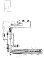
Fig. 1 zeigt ein Ausführungsbeispiel für eine erfindungsgemäße Anlage zur Umwandlung von geothermischer Energie in elektrische Energie und Wärmeenergie,
und -
Fig. 2 zeigt ein Ausführungsbeispiel für eine erfindungsgemäße Anlage zur Umwandlung von geothermischer Energie in elektrische Energie. - Das erste Ausführungsbeispiel für die erfindungsgemäße Anlage zur Umwandlung von geothermischer Energie wird nachfolgend mit Bezug auf
Fig. 1 beschrieben. - Die Hauptsonde 1 der Erdwärmesonde ist mit ca. 3.000 Liter eines Antifrogen gefüllt, wobei das Bohrloch(Teufe), in welches die Erdwärmesonde in üblicher Art und Weise eingebracht ist, ca. 42 m tief ist. Das Antifrogen dient als Frostschutzmittel, um das Einfrieren des Wassers in der Erdwärmesonde zu vermeiden.
- Alternativ können andere auf dem freien Markt verfügbare Frostschutzmittel eingesetzt werden, hilfsweise auch Salzwasser oder mit Leichtöl versetztes Wasser, was ebenfalls das unerwünschte Einfrieren verhindert.
- Zusätzlich kann die Hauptsonde 1 auf den ersten zehn Tiefenmetern, von der Erdoberfläche aus gesehen, mit einer thermischen Isolation 1.a ausgerüstet werden.
- In die mit Antifrogen gefüllte Hauptsonde 1 ist ein Verbindungsrohr, 2,5 cm Ø Innenmaß, 40m Länge, mit integrierten Gegenstromverdampfern 1.2; 1.2.1; 1.2.2, mit einer Gesamtlänge von 3 x 3,40m (insgesamt 10,20m) und einer Leistung von bis zu 30 KW, eingelassen und kann an mindestens drei Stellen sowie am Boden der Sonde verankert sein. Die Gegenstromverdampfer 1.2; 1.2.1; 1.2.2 sind in der unteren Hälfte der Hauptsonde 1 anzuordnen.
- Je nach technischer Bauweise und Anordnung können im Sinne der Erfindung alternativ auch mehr als drei Gegenstromverdampfer eingebaut werden, jedoch wird die erzielte Leistung von bis 30 KW, aufgrund der Wechselwirkung mit der Gebirgstemperatur von ca. 10°C und der Temperatur des Antifrogens (ca. 3 - 8°C), bzw. bestenfalls nur marginal mit größerer Teufe, erhöht.
- Die in zwei Kammern a/b geteilten Gegenstromverdampfer 1.2; 1.2.1; 1.2.2 sind auf einer Seite die Kammer a mit dem Kühlmittel Ammoniak (NH3) mit einer Temperatur von ca. -10°C, und auf der anderen Seite die Kammer b mit einem Antifrogen mit einer Temperatur von ca. +4°C-+7°C gefüllt.
- Alternativ kann ein anderes Kühlmittel (z.B. CO2, Propan, Butan, etc.) als Ersatz für NH3 genutzt werden, was jedoch die Effektivität und damit die Gasfördermenge verringert.
- Durch die Temperaturspreizung der beiden Flüssigkeiten in den Gegenstromverdampfern 1.2; 1.2.1; 1.2.2 entsteht eine chemische Reaktion, welche im Ergebnis das benötigte Ammoniakgas durch Verdampfung produziert.
- Die Verdampfung beginnt in dem ersten, in Reihe geschalteten Gegenstromverdampfer 1.2 und bildet Nassdampf. Dieser Nassdampf wird im zweiten Gegenstromverdampfer 1.2.1 abermals verdampft und in den dritten Gegenstromverdampfer 1.2.2 für die letzte Verdampfung überführt. Die durch Verdampfung produzierte Menge Ammoniakgas nach der letzten Verdampfung beträgt (+/-) 40 m3/h und steht als Sattdampf zur Verfügung.
- Am unteren Ende des letzten Gegenstromverdampfers 1.2.2 steigt der Sattdampf auf natürlichem Wege durch die jetzt wieder nach oben geführte Sonde zur Erdoberfläche.
- Nach Austritt aus dem Boden wird das Ammoniakgas über ein Expansionsventil 1.3 in einen Gegenstromüberhitzer 1.4 zur weiteren Trocknung geleitet und steht nun als
- Das geförderte Trockengas wird dann über einen Durchflussmengenmesser 1.4.1 in einen Kolbenverdichter 1.5 mit einer Leistung von 75 KW geleitet und auf den gewünschten Druck verdichtet. Nach der Verdichtung gelangt das Gas über den Enthitzer und den Kondensator, ausgelegt als Gegenstromtauscher, in einen Druckbehälter als NH3 -Abscheider und steht zur Abnahme von Energie bereit.
- Das in Kammer b befindliche Ammoniak wird nach der Verdampfung im Druckbehälter wieder in den Enthitzer und den Kondensator ausgelegt als Gegenstromtauscher, rückgeführt, den gebäudeeigenen Heizkessel zur Versorgung
mit Wärme bereit gestellt - Nach erfolgter Energieabgabe (1./2. und/oder 1 + 2) wird das flüssige Ammoniak über den Enthitzer 1.7, ausgelegt als Gegenstromtauscher, in den Gesamtkreislauf zurückgeführt.
- Das flüssige Ammoniak gelangt, nach dem zwischengeschalteten Durchflussmengenmesser 1.4.1, wieder über den Gegenstromüberhitzer 1.4 in den Unterkühler 1.9, welcher die Temperatur auf ca. 20°C absenkt. Das Ammoniak aus dem Unterkühler 1.9 wird nun zur Unterstützung und zur ständigen Umwälzung und Erwärmung des Antifrogen in die Hauptsonde 1 geleitet und anschließend als Rücklauf wieder in den Unterkühler 1.9 und von dort in einen Kältemittelsammler mit Ölabschneider 2 und über das Magnetventil 2.1 in einen Gegenstromverdampfer 3 mit einer Leistung von 50 KW überführt.
- Bevor das Ammoniak aus dem Unterkühler 1.9 in die Hauptsonde 1 geleitet wird, kann über eine zwischengeschaltete Pumpe P und einem Wärmetauscher P1 ein Kälteabnehmer, z.B. eine Klimaanlage oder eine andere Kühleinrichtung, mit Temperaturen von rd. 3 - 7°C, versorgt werden.
- Der Rücklauf aus dem Kälteabnehmer wird wieder durch den Wärmetauscher P1 geleitet und der Hauptsonde 1, wie oben beschrieben, zugeführt, bevor es über das Magnetventil 2.1 und den Kältemittelsammler mit Ölabscheider 2 in zwei Gegenstromvorverdampfer 3, überführt wird.
- Der Gegenstromvorverdampfer 3 verdampft das flüssige Ammoniak, über ein Ventil wird das Ammoniak wieder durch das Innenrohr 1.1 in der Hauptsonde 1 den Gegenstromverdampfern 1.2; 1.2.1; 1.2.2 zugeführt wird.
Der Gesamtprozess beginnt von vorne. - Das zweite Ausführungsbeispiel für die erfindungsgemäße Anlage zur Umwandlung von geothermischer Energie wird nachfolgend mit Bezug auf
Fig. 2 beschrieben. Wird, wie in diesem Ausführungsbeispiel, das erfindungsgemäße Verfahren ausschließlich zur Verstromung genutzt, entfällt die im ersten Ausführungsbeispiel beschriebene Versorgung mit Wärme zu Heizzwecken bzw. die diesbezüglichen Anlagenteile. - Die beiden Nutzungsarten, Wärmelieferung und Verstromung, können parallel und/oder ergänzend sowie austauschbar eingesetzt werden.
- Der erfindungsgemäß eingesetzte Gasdruckmotor M besitzt beispielsweise die folgenden technischen Daten:
Typ: Drehkolben Gasdruckmotor < 50 KW elektrische Leistung Mengenverbrauch: ca. 120 m3 pro Stunde bei ca. 35 KW elektrischer Leistung - Aus dem in der Anlage integriertem Verdichter strömt das Gas aus einem Druckbehälter, bei einer Temperatur von <15°C und mit einem Druck von < 4 Bar, in den Gasdruckmotor.
Energiebedarf: 651 cm3 pro Umdrehung (RPM) - Bei einer Umdrehungszahl von 3.000 RPM werden 1.953 Liter Gas/Min. (1,953 m3) benötigt.
Gerundet: ca. 120 m3 pro Stunde (2 x 60) - Über eine Magnetkupplung am Gasdruckmotor wird ein geeigneter Generator angetrieben, welcher mit einer Netzeinspeisevorrichtung eine elektrische Leistung von bis< 35 KW an den Einspeisepunkt abgibt.
- Wichtig ist einen Wechselstromgenerator zu wählen (keinen Gleichstromgenerator), da im Dauerbetrieb (< 8.500 Std./p.a.) Fluktuationen und damit Schwankungen der Umdrehungszahl, im Gasdruckmotor möglich sind.
- Um auf eine max. elektrische Auslastung des Gasdruckmotors zu kommen (bei o.g. Input <35 KW), muss die Gasmenge entsprechend erhöht werden, was teilweise mit der erfindungsgemäß eingesetzten Erdwärmesonde lösbar ist.
Alternativ kann eine zweite Erdwärmesonde gesetzt werden, um die geförderte Gasmenge zu erhöhen. - Nach dem Verdichter strömt das heiße Gas, bis ca. 130°C, über ein Ölabscheider und ein Dreiwegeventil in den Gasmotor.
Im Gasdruckmotor erfolgt eine Druckumwandlung von max. 15 bar auf 3-4 bar. dabei kondensiert das trockene Gas. Die entstandene Energie wird an einen Generator G abgegeben, der die Energie in einen üblichen Abnehmer einspeist.
Das kondensierte NH3 gelangt wieder in den NH3 -Abscheider.
Der NH3-Abschneider hat einen standardmäßigen Betriebsdruck von 16 Bar, einen Inhalt von 0,2 m3 und eine Leistung von 70 KW bei einer Kondensationstemperatur von 45°C. - Die Abmessung und Ausführung des Abscheiders richtet sich nach den entsprechenden kältetechnischen Erfordernissen.
- Das Gas strömt nun über Verbindungsleitungen in den Vorverdampfer und über Ventile in die Geoverdampfer, welche in der Erdwärmesonde als Röhrentauscher ausgebildet sind, und verdampft dort weiter. Die Verdampfer werden in Reihe eingebaut und werden separat, je nach Bedarf, geregelt, wobei jeder mit einer bestimmten KW Leistung ausgelegt ist.
- Die Anlage erbringt mit dieser Bauweise eine Gesamtleistung von 75KW Wärme - eine Vervierfachung der bisherigen Leistung. Durch eine gezielte, jedoch übliche Steuerung der einzelnen Wärmetauscher ist es möglich, den Bedarf an Wärmeleistung zu regulieren.
- Die Effektivität der erfindungsgemäßen Anlage wird dadurch garantiert, dass eine kontinuierliche geothermische Energiequelle bereit steht und mit der Unterstützung von Wärmetauschern ein höherer Bedarf abgesichert werden kann. Hinzu kommt, dass neben der Wärmeleistung auch Kälteleistung bereitgestellt werden kann.
-
- 1
- Hauptsonde
- 1.a
- thermische Isolation
- 1.1
- Verbindungsrohr
- 1.2; 1.2.1; 1.2.2
- Gegenstromverdampfer
- 1.3
- Expansionsventil
- 1.4
- Gegenstromüberhitzer
- 1.4.1
- Durchflussmengenmesser
- 1.5
- Kolbenverdichter
- 1.7
- Enthitzer
- 1.8
- Druckbehälter
- 1.8.1
- Lagertank
- 1.9
- Unterkühler
- 2
- Ölabschneider
- 2.1
- Magnetventil
- 3
- Gegenstromverdampfer
- M
- Gasdruckmotor (1.8.2)
- G
- Generator
- P
- Pumpe
- P1
- Wärmetauscher
Claims (8)
- Verfahren zur Umwandlung von geothermischer Energie, wobei mit zumindest einer Erdwärmesonde, vom Erdreich Wärmeenergie auf ein flüssiges Medium übertragen wird, diese Energie vom flüssigen Medium auf ein flüssiges Wärmeträgermittel übertragen wird, diese Energie vom flüssigen Wärmeträgermittel auf ein Kälteträgermittel im Gegenstrom übertragen wird, wobei dabei das Kälteträgermittel in einen gasförmigen Zustand überführt wird, nachfolgend die Energie des Kälteträgermittels in eine Rotationsbewegung umgewandelt wird und die Energie der Rotationsbewegung mit einem Generator in elektrische Energie umgewandelt wird, dadurch gekennzeichnet, dass das Verfahren kontinuierlich betreibbar ist, die Energie des Kälteträgermittels in einem Gasdruckmotor in eine Rotationsbewegung umgesetzt wird, wobei das gasförmige Kältemittel kontinuierlich am Gasdruckmotor anliegt, der Generator ein Wechselstromgenerator ist, zumindest das Kälteträgermittel in einem geschlossenen Kreislauf geführt wird und das Kälteträgermittel Ammoniak ist.
- Verfahren gemäß Anspruch 1, dadurch gekennzeichnet, dass die Erdwärmesonde eine solche ist, welche zumindest bestehend aus einer Hauptsonde (1), welche zumindest umfasst:- einen Verdampferraum, welcher aus zumindest einer Kältemittel-Kammer eines Gegenstromverdampfers (1.2; 1.2.1; 1.2.2) besteht und einem geschlossenen Kältemittel-Kreislauf angeordnet ist,- einer Steigleitung, welche mit dem unteren Ende des Verdampferraums (2.1) verbunden ist,- einer Zuleitung, welche mit dem Verdampferraum verbunden ist und im Kältemittel-Kreislauf angeordnet ist,- einem Wärmetauscherraum (2.3), welcher aus zumindest einer Wärmemittel-Kammer des Gegenstromverdampfers (1.2; 1.2.1; 1.2.2) besteht und in einem Hauptsonden-Wärmemittel-Kreislauf eines Wärmemittels angeordnet ist, und einer Zubringersonde, welche zumindest umfasst:- einen Außenmantel, welcher an seiner äußeren Seite vom Erdreich umschlossen ist,- einem Sondenzwischenraum, welcher zumindest teilweise durch die innere Seite des Außenmantels und einem Sondenboden begrenzt wird, in welchem die Hauptsonde (1) angeordnet ist, und zumindest einem Zulauf, für das flüssige Wärmemittel, welcher in zumindest einem offenen Zubringersonden-Wärmemittel-Kreislauf eines Wärmemittels angeordnet ist.
- Verfahren gemäß Anspruch 1 oder 2, dadurch gekennzeichnet, dass die Erdwärmesonde eine Mess- und Regeleinrichtung besitzt, welche in die Prozesssteuerung zur Bereitstellung eines kontinuierlichen gasförmigen Kältemittelstromes integriert ist.
- Verfahren gemäß Anspruch 1, dadurch gekennzeichnet, dass die Umwandlung von geothermischer Energie in elektrische Energie und/oder in Wärmeenergie erfolgt.
- Anlage zur Umwandlung von geothermischer Energie unter Verwendung eines Verfahrens gemäß zumindest einem der Ansprüchen 1 bis 4.
- Anlage gemäß Anspruch 5, dadurch gekennzeichnet, dass diese zumindest eine Erdwärmesonde, einen Gasdruckmotor M und einen Wechselstromgenerator G besitzt.
- Anlage gemäß Anspruch 5, dadurch gekennzeichnet, dass die Erdwärmesonde bis zu einer Tiefe von maximal 50 m, insbesondere bis zu 42 m, im Erdboden angeordnet ist.
- Anlage gemäß Anspruch 5, dadurch gekennzeichnet, dass diese eine maximale Gesamtleistung von 75KW Wärmeleistung besitzt, wobei mit einer Netzeinspeisevorrichtung eine elektrische Leistung von < 35 KW an den Einspeisepunkt abgibt.
Priority Applications (1)
| Application Number | Priority Date | Filing Date | Title |
|---|---|---|---|
| EP13004458.9A EP2848778B1 (de) | 2013-09-12 | 2013-09-12 | Verfahren und Anlage zur Umwandlung von geothermischer Energie |
Applications Claiming Priority (1)
| Application Number | Priority Date | Filing Date | Title |
|---|---|---|---|
| EP13004458.9A EP2848778B1 (de) | 2013-09-12 | 2013-09-12 | Verfahren und Anlage zur Umwandlung von geothermischer Energie |
Publications (2)
| Publication Number | Publication Date |
|---|---|
| EP2848778A1 true EP2848778A1 (de) | 2015-03-18 |
| EP2848778B1 EP2848778B1 (de) | 2021-07-21 |
Family
ID=49212545
Family Applications (1)
| Application Number | Title | Priority Date | Filing Date |
|---|---|---|---|
| EP13004458.9A Active EP2848778B1 (de) | 2013-09-12 | 2013-09-12 | Verfahren und Anlage zur Umwandlung von geothermischer Energie |
Country Status (1)
| Country | Link |
|---|---|
| EP (1) | EP2848778B1 (de) |
Citations (3)
| Publication number | Priority date | Publication date | Assignee | Title |
|---|---|---|---|---|
| DE202012003480U1 (de) | 2012-04-05 | 2012-05-29 | ThermaEnergy GmbH & Co. KG | Erdwärmesonde |
| US20120317983A1 (en) * | 2011-06-15 | 2012-12-20 | Kalex, Llc | Systems and methods extracting useable energy from low temperature sources |
| US20130213040A1 (en) * | 2010-02-22 | 2013-08-22 | University Of South Florida | Method and system for generating power from low- and mid- temperature heat sources |
-
2013
- 2013-09-12 EP EP13004458.9A patent/EP2848778B1/de active Active
Patent Citations (3)
| Publication number | Priority date | Publication date | Assignee | Title |
|---|---|---|---|---|
| US20130213040A1 (en) * | 2010-02-22 | 2013-08-22 | University Of South Florida | Method and system for generating power from low- and mid- temperature heat sources |
| US20120317983A1 (en) * | 2011-06-15 | 2012-12-20 | Kalex, Llc | Systems and methods extracting useable energy from low temperature sources |
| DE202012003480U1 (de) | 2012-04-05 | 2012-05-29 | ThermaEnergy GmbH & Co. KG | Erdwärmesonde |
Also Published As
| Publication number | Publication date |
|---|---|
| EP2848778B1 (de) | 2021-07-21 |
Similar Documents
| Publication | Publication Date | Title |
|---|---|---|
| EP2900943B1 (de) | Kraft-wärme-kraftwerk und verfahren zum betrieb eines kraft-wärme-kraftwerks | |
| EP2994699A1 (de) | Wärmetechnische verschaltung einer geothermiequelle mit einem fernwärmenetz | |
| EP3614069A1 (de) | Verfahren und Einrichtung zur Gewinnung von Nutzenenergie aus Erdwärme | |
| DE102010033956A1 (de) | Druckgasspeichervorrichtung mit mindestens einem Druckgastank und mit einer Wärmeaufnahme- und/oder Wärmeübertragungsvorrichtung, insbesondere mit einem Wärmetauscher | |
| DE202022101249U1 (de) | Wärmepumpensystem und Quartier | |
| Rostamzadeh | Indirect mechanical heat pump assisted humidification‐dehumidification desalination systems | |
| DE102005011239A1 (de) | Verfahren und Anordnung zum Betrieb einer Anlage zur Gewinnung und Speicherung von Erdwärme und Erdkälte | |
| EP2848778B1 (de) | Verfahren und Anlage zur Umwandlung von geothermischer Energie | |
| WO2008025334A2 (de) | Hausenergieversorgungsanlage | |
| WO2021139846A1 (de) | Verfahren zur co2-verflüssigung und -speicherung in einem co2-kraftwerk | |
| DE202013008058U1 (de) | Anlage zur Umwandlung von geothermischer Energie | |
| DE102009060887A1 (de) | System zur Umwandlung von thermischer Energie in elektrische Energie | |
| DE19860328B4 (de) | Wärmeübertrager | |
| DE102010034616A1 (de) | Verfahren und Vorrichtung zur Speicherung von Wärme und Kälte mittels einer Wärmepumpe | |
| DE102009036123A1 (de) | Kälte-Wärme-Kopplungsanlage | |
| DE202012003480U1 (de) | Erdwärmesonde | |
| DE102010027601A1 (de) | Kopplung von Solarkollektoren und Wärmepumpen mit variabler Expansionstemperatur | |
| DE102013019756B4 (de) | Energieversorgungssystem sowie Energieversorgungsmodul zur Verwendung in einem solchen Energieversorgungssystem | |
| DE102012014513B4 (de) | Energieversorgungsanlage | |
| EP2473715A2 (de) | Verfahren und einrichtung zur energieerzeugung insbesondere aus biomasse oder biomasseenergieträgern | |
| DE19642702A1 (de) | Wärmepumpenanlage | |
| EP4520865A1 (de) | Wäschereisystem und verfahren zum betrieb eines wäschereisystems | |
| DE202026100480U1 (de) | Vorrichtung zur Nutzung geothermischer Energie | |
| DE202005001570U1 (de) | Wärmeerzeuger | |
| EP2647924A1 (de) | Erdwärmesonde |
Legal Events
| Date | Code | Title | Description |
|---|---|---|---|
| PUAI | Public reference made under article 153(3) epc to a published international application that has entered the european phase |
Free format text: ORIGINAL CODE: 0009012 |
|
| 17P | Request for examination filed |
Effective date: 20130912 |
|
| AK | Designated contracting states |
Kind code of ref document: A1 Designated state(s): AL AT BE BG CH CY CZ DE DK EE ES FI FR GB GR HR HU IE IS IT LI LT LU LV MC MK MT NL NO PL PT RO RS SE SI SK SM TR |
|
| AX | Request for extension of the european patent |
Extension state: BA ME |
|
| R17P | Request for examination filed (corrected) |
Effective date: 20150916 |
|
| RBV | Designated contracting states (corrected) |
Designated state(s): AL AT BE BG CH CY CZ DE DK EE ES FI FR GB GR HR HU IE IS IT LI LT LU LV MC MK MT NL NO PL PT RO RS SE SI SK SM TR |
|
| RAP1 | Party data changed (applicant data changed or rights of an application transferred) |
Owner name: INTERNATIONAL MERGER & ACQUISITION CORPORATION Owner name: LIPP, THOMAS |
|
| GRAP | Despatch of communication of intention to grant a patent |
Free format text: ORIGINAL CODE: EPIDOSNIGR1 |
|
| STAA | Information on the status of an ep patent application or granted ep patent |
Free format text: STATUS: GRANT OF PATENT IS INTENDED |
|
| INTG | Intention to grant announced |
Effective date: 20210325 |
|
| GRAS | Grant fee paid |
Free format text: ORIGINAL CODE: EPIDOSNIGR3 |
|
| GRAA | (expected) grant |
Free format text: ORIGINAL CODE: 0009210 |
|
| STAA | Information on the status of an ep patent application or granted ep patent |
Free format text: STATUS: THE PATENT HAS BEEN GRANTED |
|
| AK | Designated contracting states |
Kind code of ref document: B1 Designated state(s): AL AT BE BG CH CY CZ DE DK EE ES FI FR GB GR HR HU IE IS IT LI LT LU LV MC MK MT NL NO PL PT RO RS SE SI SK SM TR |
|
| REG | Reference to a national code |
Ref country code: GB Ref legal event code: FG4D Free format text: NOT ENGLISH |
|
| REG | Reference to a national code |
Ref country code: CH Ref legal event code: EP |
|
| REG | Reference to a national code |
Ref country code: DE Ref legal event code: R096 Ref document number: 502013015829 Country of ref document: DE |
|
| REG | Reference to a national code |
Ref country code: AT Ref legal event code: REF Ref document number: 1412788 Country of ref document: AT Kind code of ref document: T Effective date: 20210815 |
|
| REG | Reference to a national code |
Ref country code: IE Ref legal event code: FG4D Free format text: LANGUAGE OF EP DOCUMENT: GERMAN |
|
| REG | Reference to a national code |
Ref country code: FI Ref legal event code: FGE |
|
| REG | Reference to a national code |
Ref country code: NO Ref legal event code: T2 Effective date: 20210721 |
|
| REG | Reference to a national code |
Ref country code: SE Ref legal event code: TRGR |
|
| REG | Reference to a national code |
Ref country code: LT Ref legal event code: MG9D |
|
| REG | Reference to a national code |
Ref country code: NL Ref legal event code: MP Effective date: 20210721 |
|
| PG25 | Lapsed in a contracting state [announced via postgrant information from national office to epo] |
Ref country code: HR Free format text: LAPSE BECAUSE OF FAILURE TO SUBMIT A TRANSLATION OF THE DESCRIPTION OR TO PAY THE FEE WITHIN THE PRESCRIBED TIME-LIMIT Effective date: 20210721 Ref country code: BG Free format text: LAPSE BECAUSE OF FAILURE TO SUBMIT A TRANSLATION OF THE DESCRIPTION OR TO PAY THE FEE WITHIN THE PRESCRIBED TIME-LIMIT Effective date: 20211021 Ref country code: LT Free format text: LAPSE BECAUSE OF FAILURE TO SUBMIT A TRANSLATION OF THE DESCRIPTION OR TO PAY THE FEE WITHIN THE PRESCRIBED TIME-LIMIT Effective date: 20210721 Ref country code: RS Free format text: LAPSE BECAUSE OF FAILURE TO SUBMIT A TRANSLATION OF THE DESCRIPTION OR TO PAY THE FEE WITHIN THE PRESCRIBED TIME-LIMIT Effective date: 20210721 Ref country code: PT Free format text: LAPSE BECAUSE OF FAILURE TO SUBMIT A TRANSLATION OF THE DESCRIPTION OR TO PAY THE FEE WITHIN THE PRESCRIBED TIME-LIMIT Effective date: 20211122 Ref country code: NL Free format text: LAPSE BECAUSE OF FAILURE TO SUBMIT A TRANSLATION OF THE DESCRIPTION OR TO PAY THE FEE WITHIN THE PRESCRIBED TIME-LIMIT Effective date: 20210721 Ref country code: ES Free format text: LAPSE BECAUSE OF FAILURE TO SUBMIT A TRANSLATION OF THE DESCRIPTION OR TO PAY THE FEE WITHIN THE PRESCRIBED TIME-LIMIT Effective date: 20210721 |
|
| PG25 | Lapsed in a contracting state [announced via postgrant information from national office to epo] |
Ref country code: PL Free format text: LAPSE BECAUSE OF FAILURE TO SUBMIT A TRANSLATION OF THE DESCRIPTION OR TO PAY THE FEE WITHIN THE PRESCRIBED TIME-LIMIT Effective date: 20210721 Ref country code: LV Free format text: LAPSE BECAUSE OF FAILURE TO SUBMIT A TRANSLATION OF THE DESCRIPTION OR TO PAY THE FEE WITHIN THE PRESCRIBED TIME-LIMIT Effective date: 20210721 Ref country code: GR Free format text: LAPSE BECAUSE OF FAILURE TO SUBMIT A TRANSLATION OF THE DESCRIPTION OR TO PAY THE FEE WITHIN THE PRESCRIBED TIME-LIMIT Effective date: 20211022 |
|
| REG | Reference to a national code |
Ref country code: DE Ref legal event code: R097 Ref document number: 502013015829 Country of ref document: DE |
|
| PG25 | Lapsed in a contracting state [announced via postgrant information from national office to epo] |
Ref country code: DK Free format text: LAPSE BECAUSE OF FAILURE TO SUBMIT A TRANSLATION OF THE DESCRIPTION OR TO PAY THE FEE WITHIN THE PRESCRIBED TIME-LIMIT Effective date: 20210721 |
|
| REG | Reference to a national code |
Ref country code: BE Ref legal event code: MM Effective date: 20210930 |
|
| PLBE | No opposition filed within time limit |
Free format text: ORIGINAL CODE: 0009261 |
|
| STAA | Information on the status of an ep patent application or granted ep patent |
Free format text: STATUS: NO OPPOSITION FILED WITHIN TIME LIMIT |
|
| PG25 | Lapsed in a contracting state [announced via postgrant information from national office to epo] |
Ref country code: SM Free format text: LAPSE BECAUSE OF FAILURE TO SUBMIT A TRANSLATION OF THE DESCRIPTION OR TO PAY THE FEE WITHIN THE PRESCRIBED TIME-LIMIT Effective date: 20210721 Ref country code: SK Free format text: LAPSE BECAUSE OF FAILURE TO SUBMIT A TRANSLATION OF THE DESCRIPTION OR TO PAY THE FEE WITHIN THE PRESCRIBED TIME-LIMIT Effective date: 20210721 Ref country code: RO Free format text: LAPSE BECAUSE OF FAILURE TO SUBMIT A TRANSLATION OF THE DESCRIPTION OR TO PAY THE FEE WITHIN THE PRESCRIBED TIME-LIMIT Effective date: 20210721 Ref country code: MC Free format text: LAPSE BECAUSE OF FAILURE TO SUBMIT A TRANSLATION OF THE DESCRIPTION OR TO PAY THE FEE WITHIN THE PRESCRIBED TIME-LIMIT Effective date: 20210721 Ref country code: EE Free format text: LAPSE BECAUSE OF FAILURE TO SUBMIT A TRANSLATION OF THE DESCRIPTION OR TO PAY THE FEE WITHIN THE PRESCRIBED TIME-LIMIT Effective date: 20210721 Ref country code: CZ Free format text: LAPSE BECAUSE OF FAILURE TO SUBMIT A TRANSLATION OF THE DESCRIPTION OR TO PAY THE FEE WITHIN THE PRESCRIBED TIME-LIMIT Effective date: 20210721 Ref country code: AL Free format text: LAPSE BECAUSE OF FAILURE TO SUBMIT A TRANSLATION OF THE DESCRIPTION OR TO PAY THE FEE WITHIN THE PRESCRIBED TIME-LIMIT Effective date: 20210721 |
|
| 26N | No opposition filed |
Effective date: 20220422 |
|
| GBPC | Gb: european patent ceased through non-payment of renewal fee |
Effective date: 20211021 |
|
| PG25 | Lapsed in a contracting state [announced via postgrant information from national office to epo] |
Ref country code: LU Free format text: LAPSE BECAUSE OF NON-PAYMENT OF DUE FEES Effective date: 20210912 Ref country code: IE Free format text: LAPSE BECAUSE OF NON-PAYMENT OF DUE FEES Effective date: 20210912 Ref country code: GB Free format text: LAPSE BECAUSE OF NON-PAYMENT OF DUE FEES Effective date: 20211021 Ref country code: BE Free format text: LAPSE BECAUSE OF NON-PAYMENT OF DUE FEES Effective date: 20210930 |
|
| REG | Reference to a national code |
Ref country code: AT Ref legal event code: MM01 Ref document number: 1412788 Country of ref document: AT Kind code of ref document: T Effective date: 20210912 |
|
| PG25 | Lapsed in a contracting state [announced via postgrant information from national office to epo] |
Ref country code: AT Free format text: LAPSE BECAUSE OF NON-PAYMENT OF DUE FEES Effective date: 20210912 |
|
| REG | Reference to a national code |
Ref country code: DE Ref legal event code: R082 Ref document number: 502013015829 Country of ref document: DE Representative=s name: WEIDNER STERN JESCHKE PATENTANWAELTE PARTNERSC, DE |
|
| PG25 | Lapsed in a contracting state [announced via postgrant information from national office to epo] |
Ref country code: HU Free format text: LAPSE BECAUSE OF FAILURE TO SUBMIT A TRANSLATION OF THE DESCRIPTION OR TO PAY THE FEE WITHIN THE PRESCRIBED TIME-LIMIT; INVALID AB INITIO Effective date: 20130912 |
|
| PG25 | Lapsed in a contracting state [announced via postgrant information from national office to epo] |
Ref country code: CY Free format text: LAPSE BECAUSE OF FAILURE TO SUBMIT A TRANSLATION OF THE DESCRIPTION OR TO PAY THE FEE WITHIN THE PRESCRIBED TIME-LIMIT Effective date: 20210721 |
|
| P01 | Opt-out of the competence of the unified patent court (upc) registered |
Effective date: 20230530 |
|
| PGFP | Annual fee paid to national office [announced via postgrant information from national office to epo] |
Ref country code: NO Payment date: 20230919 Year of fee payment: 11 Ref country code: FI Payment date: 20230918 Year of fee payment: 11 |
|
| PGFP | Annual fee paid to national office [announced via postgrant information from national office to epo] |
Ref country code: SE Payment date: 20230921 Year of fee payment: 11 Ref country code: IS Payment date: 20230925 Year of fee payment: 11 Ref country code: FR Payment date: 20230918 Year of fee payment: 11 Ref country code: DE Payment date: 20230725 Year of fee payment: 11 |
|
| PGFP | Annual fee paid to national office [announced via postgrant information from national office to epo] |
Ref country code: IT Payment date: 20230929 Year of fee payment: 11 Ref country code: CH Payment date: 20231001 Year of fee payment: 11 |
|
| PG25 | Lapsed in a contracting state [announced via postgrant information from national office to epo] |
Ref country code: MK Free format text: LAPSE BECAUSE OF FAILURE TO SUBMIT A TRANSLATION OF THE DESCRIPTION OR TO PAY THE FEE WITHIN THE PRESCRIBED TIME-LIMIT Effective date: 20210721 |
|
| PG25 | Lapsed in a contracting state [announced via postgrant information from national office to epo] |
Ref country code: MT Free format text: LAPSE BECAUSE OF FAILURE TO SUBMIT A TRANSLATION OF THE DESCRIPTION OR TO PAY THE FEE WITHIN THE PRESCRIBED TIME-LIMIT Effective date: 20210721 |
|
| REG | Reference to a national code |
Ref country code: DE Ref legal event code: R119 Ref document number: 502013015829 Country of ref document: DE |
|
| PG25 | Lapsed in a contracting state [announced via postgrant information from national office to epo] |
Ref country code: FI Free format text: LAPSE BECAUSE OF NON-PAYMENT OF DUE FEES Effective date: 20240912 |
|
| REG | Reference to a national code |
Ref country code: SE Ref legal event code: EUG |
|
| REG | Reference to a national code |
Ref country code: CH Ref legal event code: PL |
|
| PG25 | Lapsed in a contracting state [announced via postgrant information from national office to epo] |
Ref country code: DE Free format text: LAPSE BECAUSE OF NON-PAYMENT OF DUE FEES Effective date: 20250401 |
|
| PG25 | Lapsed in a contracting state [announced via postgrant information from national office to epo] |
Ref country code: NO Free format text: LAPSE BECAUSE OF NON-PAYMENT OF DUE FEES Effective date: 20240930 |
|
| PG25 | Lapsed in a contracting state [announced via postgrant information from national office to epo] |
Ref country code: IT Free format text: LAPSE BECAUSE OF NON-PAYMENT OF DUE FEES Effective date: 20240912 |
|
| PG25 | Lapsed in a contracting state [announced via postgrant information from national office to epo] |
Ref country code: FR Free format text: LAPSE BECAUSE OF NON-PAYMENT OF DUE FEES Effective date: 20240930 |
|
| PG25 | Lapsed in a contracting state [announced via postgrant information from national office to epo] |
Ref country code: CH Free format text: LAPSE BECAUSE OF NON-PAYMENT OF DUE FEES Effective date: 20240930 |
|
| PG25 | Lapsed in a contracting state [announced via postgrant information from national office to epo] |
Ref country code: SE Free format text: LAPSE BECAUSE OF NON-PAYMENT OF DUE FEES Effective date: 20240913 |
|
| PG25 | Lapsed in a contracting state [announced via postgrant information from national office to epo] |
Ref country code: TR Free format text: LAPSE BECAUSE OF FAILURE TO SUBMIT A TRANSLATION OF THE DESCRIPTION OR TO PAY THE FEE WITHIN THE PRESCRIBED TIME-LIMIT Effective date: 20210721 |