EP2847747B1 - Autonomes system zur kollisionsverhinderung eines satelliten mt orbitalem schrott - Google Patents
Autonomes system zur kollisionsverhinderung eines satelliten mt orbitalem schrott Download PDFInfo
- Publication number
- EP2847747B1 EP2847747B1 EP13787040.8A EP13787040A EP2847747B1 EP 2847747 B1 EP2847747 B1 EP 2847747B1 EP 13787040 A EP13787040 A EP 13787040A EP 2847747 B1 EP2847747 B1 EP 2847747B1
- Authority
- EP
- European Patent Office
- Prior art keywords
- debris
- satellite
- orbital
- data
- collision
- Prior art date
- Legal status (The legal status is an assumption and is not a legal conclusion. Google has not performed a legal analysis and makes no representation as to the accuracy of the status listed.)
- Active
Links
Images

Classifications
-
- B—PERFORMING OPERATIONS; TRANSPORTING
- B64—AIRCRAFT; AVIATION; COSMONAUTICS
- B64G—COSMONAUTICS; VEHICLES OR EQUIPMENT THEREFOR
- B64G1/00—Cosmonautic vehicles
- B64G1/22—Parts of, or equipment specially adapted for fitting in or to, cosmonautic vehicles
- B64G1/52—Protection, safety or emergency devices; Survival aids
- B64G1/56—Protection against meteoroids or space debris
-
- B—PERFORMING OPERATIONS; TRANSPORTING
- B64—AIRCRAFT; AVIATION; COSMONAUTICS
- B64G—COSMONAUTICS; VEHICLES OR EQUIPMENT THEREFOR
- B64G1/00—Cosmonautic vehicles
- B64G1/10—Artificial satellites; Systems of such satellites; Interplanetary vehicles
-
- B—PERFORMING OPERATIONS; TRANSPORTING
- B64—AIRCRAFT; AVIATION; COSMONAUTICS
- B64G—COSMONAUTICS; VEHICLES OR EQUIPMENT THEREFOR
- B64G1/00—Cosmonautic vehicles
- B64G1/22—Parts of, or equipment specially adapted for fitting in or to, cosmonautic vehicles
- B64G1/66—Arrangements or adaptations of apparatus or instruments, not otherwise provided for
-
- B—PERFORMING OPERATIONS; TRANSPORTING
- B64—AIRCRAFT; AVIATION; COSMONAUTICS
- B64G—COSMONAUTICS; VEHICLES OR EQUIPMENT THEREFOR
- B64G1/00—Cosmonautic vehicles
- B64G1/22—Parts of, or equipment specially adapted for fitting in or to, cosmonautic vehicles
- B64G1/24—Guiding or controlling apparatus, e.g. for attitude control
- B64G1/242—Orbits and trajectories
- B64G1/2429—Station keeping
-
- B—PERFORMING OPERATIONS; TRANSPORTING
- B64—AIRCRAFT; AVIATION; COSMONAUTICS
- B64G—COSMONAUTICS; VEHICLES OR EQUIPMENT THEREFOR
- B64G1/00—Cosmonautic vehicles
- B64G1/22—Parts of, or equipment specially adapted for fitting in or to, cosmonautic vehicles
- B64G1/24—Guiding or controlling apparatus, e.g. for attitude control
- B64G1/244—Spacecraft control systems
- B64G1/247—Advanced control concepts for autonomous, robotic spacecraft, e.g. by using artificial intelligence, neural networks or autonomous agents
-
- B—PERFORMING OPERATIONS; TRANSPORTING
- B64—AIRCRAFT; AVIATION; COSMONAUTICS
- B64G—COSMONAUTICS; VEHICLES OR EQUIPMENT THEREFOR
- B64G3/00—Observing or tracking cosmonautic vehicles
-
- G—PHYSICS
- G01—MEASURING; TESTING
- G01S—RADIO DIRECTION-FINDING; RADIO NAVIGATION; DETERMINING DISTANCE OR VELOCITY BY USE OF RADIO WAVES; LOCATING OR PRESENCE-DETECTING BY USE OF THE REFLECTION OR RERADIATION OF RADIO WAVES; ANALOGOUS ARRANGEMENTS USING OTHER WAVES
- G01S13/00—Systems using the reflection or reradiation of radio waves, e.g. radar systems; Analogous systems using reflection or reradiation of waves whose nature or wavelength is irrelevant or unspecified
- G01S13/66—Radar-tracking systems; Analogous systems
- G01S13/72—Radar-tracking systems; Analogous systems for two-dimensional [2D] tracking, e.g. combination of angle and range tracking, track-while-scan radar
-
- G—PHYSICS
- G01—MEASURING; TESTING
- G01S—RADIO DIRECTION-FINDING; RADIO NAVIGATION; DETERMINING DISTANCE OR VELOCITY BY USE OF RADIO WAVES; LOCATING OR PRESENCE-DETECTING BY USE OF THE REFLECTION OR RERADIATION OF RADIO WAVES; ANALOGOUS ARRANGEMENTS USING OTHER WAVES
- G01S13/00—Systems using the reflection or reradiation of radio waves, e.g. radar systems; Analogous systems using reflection or reradiation of waves whose nature or wavelength is irrelevant or unspecified
- G01S13/87—Combinations of radar systems, e.g. primary radar and secondary radar
-
- G—PHYSICS
- G01—MEASURING; TESTING
- G01S—RADIO DIRECTION-FINDING; RADIO NAVIGATION; DETERMINING DISTANCE OR VELOCITY BY USE OF RADIO WAVES; LOCATING OR PRESENCE-DETECTING BY USE OF THE REFLECTION OR RERADIATION OF RADIO WAVES; ANALOGOUS ARRANGEMENTS USING OTHER WAVES
- G01S13/00—Systems using the reflection or reradiation of radio waves, e.g. radar systems; Analogous systems using reflection or reradiation of waves whose nature or wavelength is irrelevant or unspecified
- G01S13/88—Radar or analogous systems specially adapted for specific applications
- G01S13/93—Radar or analogous systems specially adapted for specific applications for anti-collision purposes
- G01S13/933—Radar or analogous systems specially adapted for specific applications for anti-collision purposes of aircraft or spacecraft
-
- G—PHYSICS
- G01—MEASURING; TESTING
- G01S—RADIO DIRECTION-FINDING; RADIO NAVIGATION; DETERMINING DISTANCE OR VELOCITY BY USE OF RADIO WAVES; LOCATING OR PRESENCE-DETECTING BY USE OF THE REFLECTION OR RERADIATION OF RADIO WAVES; ANALOGOUS ARRANGEMENTS USING OTHER WAVES
- G01S7/00—Details of systems according to groups G01S13/00, G01S15/00, G01S17/00
- G01S7/003—Transmission of data between radar, sonar or lidar systems and remote stations
Definitions
- Communication and broadcast satellites can typically require up to $250 million for construction, launch and insurance. These satellites generally have a design lifetime of 15-18 years. Besides the cost of loss due to collision with orbital debris, the satellite may serve many millions of customers and its replacement typically takes three years. This results in serious loss of service to customers and of operating revenues.
- the threat trajectories are segmented into 24h, 12h, 6h, and 3h conjunctions. If at the 3h to conjunction, the debris is still considered a threat then a space-borne radar on the SSF is activated at the expected time minus 5 seconds to provide updated time of debris crossing, range, and possibly range rate and elevation angle. This information is transmitted to the ground for high-speed computer processing for providing updated debris orbit information. This updated information would then be used to determine the collision threat and assess the need to move the station.
- a system and method for satellite orbital debris avoidance according to the invention allows an operating satellite to avoid orbital debris autonomously or semi-autonomously.
- Debris tracking can be superior on the satellite, since ground station radars must contend with attenuation and errors caused by the atmosphere and ionosphere.
- Satellites generally have almost full view of the spheroid, since debris can come from any direction, whereas a single ground station can practically see somewhat under half of the spheroid.
- ground stations can overcome the coverage deficiency referred to above.
- a geostationary satellite would require three ground stations spaced about 120 degrees in longitude, and lower orbiting satellites would require many more than three ground stations.
- Such ground stations are expensive in capital and have significant operations costs including their inter-communications.
- an autonomous debris avoidance system according to the invention on larger satellites is particularly effective since much of the computing power is normally already included, making the modest equipment and programming additions feasible, and the combination of existing computer subsystems in the satellite is a particularly effective implementation.
- an operator could easily add other supplementary capabilities without any more satellite hardware and only small software additions.
- the satellite could also determine if a chosen avoidance orbit is safe from collision with other satellites and with other debris. It could also determine the effect of the chosen avoidance orbit on the satellite's system operational performance.
- An important benefit of autonomous satellite avoidance is the speed of operation, especially for random small debris which might be invisible or difficult to track by ground stations.
- the extra time required for ground station acquisition, processing, relay of the avoidance data to the satellite and its required confirmation of proper receipt could allow for the collision to occur.
- a satellite system according to claim 1 is provided.
- a satellite is constructed with such a system having an orbital debris tracking subsystem to detect and track objects using a microwave or light (LADAR) frequency radar or similar sensors/detectors.
- Detection and tracking equipment can include higher frequency microwave or laser radars, which may be preferable under certain circumstances because their resolution of debris size and motion is better, the required antenna on the satellite will be smaller and atmospheric attenuation is not a problem (since the satellite and debris are typically well above the atmosphere).
- the satellite has onboard computer capability which calculates from its radar/ladar data and from data on its own orbit (derived from onboard sensors such as star, earth and sun sensors, GPS receivers, and/or from stored data sent from its ground control station through the satellite's command subsystem) if a collision could occur.
- the computer calculates the minimum change in the satellite's orbit to avoid such collision and generates commands for firing on-board orbital control thrusters to put the satellite in an avoidance orbit.
- the computer calculates the minimum change in the satellite's orbit to avoid such collision and generates commands for firing on-board orbital control thrusters to put the satellite in an avoidance orbit.
- the computer calculates the minimum change in the satellite's orbit to avoid such collision and generates commands for firing on-board orbital control thrusters to put the satellite in an avoidance orbit.
- the computer calculates the minimum change in the satellite's orbit to avoid such collision and generates commands for firing on-board orbital control thrusters to put the satellite in an avoidance orbit.
- Detection, tracking and debris avoidance from a satellite is fundamentally superior from doing it elsewhere including from earth stations.
- Debris orbits are random and numerous, resulting in potential collision paths from anywhere in the spheroid around the satellite.
- Smaller, rapidly moving debris are particularly difficult to detect from earth stations which are often also limited by non-continuous coverage and by the inability to penetrate the atmosphere efficiently at various frequencies such as optical. Since, in many cases, avoidance must be accomplished in a very short period, autonomous operation in the satellite is faster than doing the same operations from earth station(s) due to command transit time between the station and satellite and other previously mentioned factors.
- the satellite system includes an orbital debris tracking means adapted to provide streams of tracking data on individual pieces of debris detected in the full spherical envelope around the satellite, an orbit determination processing means, an ephemeris processing means, a collision calculation means, a satellite avoidance orbit processing means, and a satellite avoidance commands processing means.
- the means can be provided as one or more separate or integrated devices or software adapted to perform one or more of the functions described herein.
- the orbit determination processing means is adapted to receive the tracking data from the orbital tracking means to compute the orbits of the debris.
- the ephemeris processing means is adapted to receive the debris orbital data from the orbital processing means and satellite orbital elements data from on-board sensors and/or the satellite's computer.
- the orbit determination processing means is adapted to provide debris orbital elements data of the debris including semi-major axis, eccentricity, inclination, right ascension of ascending node, argument of perigee, period, time of perigee and their variances.
- the ephemeris processing means is adapted to calculate location ephemeris data for future positions of the debris relative to future positions of the satellite.
- the collision calculation means is adapted to receive the location ephemeris data for a piece of debris and the location ephemeris data for the satellite from the ephemeris processing means.
- the collision calculation means is also adapted to provide a collision conclusion showing whether a collision would or would not occur at some future time between a piece of debris and said satellite.
- the satellite avoidance orbit processing means is adapted to receive output from the collision calculation means and to calculate a minimum change of the satellite's existing orbit to an orbit which avoids collision with said debris.
- the satellite avoidance commands processing means is adapted to receive the data for a minimum change in orbit, to calculate the required commands for the satellite thruster firings and to cause these commands to be executed.
- the orbital debris tracking means includes one or more radar or ladar which are adapted to provide coverage around the satellite for determining the angle, velocity and range of one or more pieces of debris from the satellite.
- the system is specifically adapted to autonomously avoid collision with orbital debris.
- the orbital debris tracking means is selected from the group comprising radar, ladar, microwave radar, and optical recognition; wherein the orbital debris tracking means include one or more modes such as pulse mode, continuous mode, and/or Doppler mode; and wherein the orbital debris tracking means include one or more operating parameters such as pulse width, beam scan, frequency shift, radiated power output and/or bandwidth.
- a first tracking means is also provided for tracking debris having a range of high speeds, relative to the satellite, and a second tracking means is further provided for tracking debris having a range of low speeds relative to the satellite.
- a first tracking means is also provided for tracking debris having a range of large sizes
- a second tracking means is further provided for tracking debris having a range of small sizes.
- the ephemeris processing means is adapted to receive a portion of the debris orbital elements data from the orbital determination processing means and a portion of the satellite orbital elements data from on-board sensors and/or the satellite's computer.
- the ephemeris processing means is adapted to receive a portion of the debris orbital elements data from one or more ground stations and a portion of the satellite orbital elements data from one or more ground stations.
- the computer collision calculation means is adapted to determine a collision likelihood envelope for each piece of debris based upon an uncertainty measurement associated with one or more factors associated with the piece of debris. Such factors include the orbit, size and/or velocity data.
- the collision calculation means is further adapted to provide an output conclusion showing whether a collision would occur at some future time between a piece of debris and a future position of said satellite after the satellite undergoes an orbital change maneuver.
- the collision calculation means is adapted to maintain a matrix of orbital maneuver choices for the satellite, wherein each matrix element includes a risk assessment of collision.
- the collision calculation means is adapted to determine if a probability of collision of the orbital debris is below a predetermined threshold and to provide a conclusion including an ignore conclusion, and to provide the output of its probability determination to other orbital debris avoidance subsystems.
- the satellite avoidance orbit processing means is further adapted to choose a solution set of orbital maneuver choices from a matrix depending on one or more predetermined satellite operational performance parameters being fully functional at each orbital maneuver choice.
- the satellite avoidance orbit processing means is further adapted to choose a solution set of orbital maneuver choices from a matrix depending on a calculation of the minimum fuel required to achieve a new orbital avoidance solution.
- one or more of the means of the system is adapted to include a debris tracking dwell time for performing more accurate calculations or other functions of that means, which calculations are associated with one or more pieces of debris and that the means is further adapted to prioritize calculations based upon position and velocity of debris.
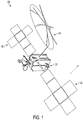
- a modern high capacity satellite 120 used for communications and broadcast purpose(s) is shown in Figure 1 which can be adapted for use with the invention.
- Such satellites typically include functional equipment including one or more satellite thrusters 121, one or more power sources 122, as well as one or more antennae 123.
- the satellite 120 can include a number of systems, including systems associated with the primary function of the satellite, such as communication, broadcast, observation, and other systems, not shown. Some of such systems and functional equipment can cooperate with or be part of an orbital debris avoidance system according to the invention.
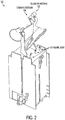
- FIG. 2 An enlargement of the main body of the satellite is shown in Figure 2 and illustrates a command antenna 124 and a telemetry antenna 125 for communication with a ground control station(s) and one possible location of three orbital tracking devices 101, namely radars or ladars or other similar sensors/detectors for tracking debris.
- the locations and numbers of the antennae and orbital tracking devices will vary from satellite to satellite.
- the orbital tracking devices are preferably located to best be able to see unobstructed the full sphere around the satellite. At least two would normally be incorporated to achieve that visibility and to provide redundancy in case of failure.
- satellite sensors e.g., sun, earth and stars
- propulsion thrusters used for orbit and attitude control
- computers/processors described below are used internal to the satellite body and the tanks holding the propulsion fuel which are used by the previously noted thrusters for controlling the satellite's orbit and attitude.
- a flow diagram in Figure 3 illustrates the typical operation of the orbital debris avoidance system 100 as implemented on a typical satellite and its possible connection to the ground control station for backup and other purposes.
- an orbital debris avoidance system 100 need not necessarily include some of the standard equipment that may be included in a satellite such as antennas, sensors and/or communication and processor devices. The following description is provided in view of this consideration.
- processors and devices described herein as having a described functionality could be provided as one or more general purpose computers or as one or more application specific integrated circuits (ASIC).
- ASIC application specific integrated circuits
- satellite orbital debris avoidance system 100 can be embodied in one or more programmed computers, and/or ASICs, which can be embodied within processors to perform the functions of the system 100 according to the invention, as described herein.
- a system 100 according to the invention can be adapted or designed to cooperate with such devices and yet fall within the scope of the invention.
- a system and method for satellite orbital debris avoidance 100 allows an operating satellite to avoid orbital debris 140 and similar objects (e.g., meteors) autonomously or semi-autonomously.
- a system 100 in Figure 2 can be designed for a satellite having at least one orbital debris tracking device 101 to detect and track objects and provide tracking data.
- the orbital debris tracking devices 101 includes a processor and one or more detector/sensors, such as microwave or light (LADAR) frequency radars.
- Detector/sensors 101 may include higher frequency microwave or laser radars, which may be preferable under certain circumstances because their resolution of debris size and motion is better, the required antenna on the satellite will be smaller and atmospheric attenuation is not a problem (since the satellite and debris are typically well above the atmosphere).
- detectors/sensors 101 can also include radar and optical sensors having recognition capability as well as other remote sensing devices. It can be appreciated by a person of ordinary skill in the art, in view of this disclosure of the invention, that variations in the orbital debris tracking device 101 can be implemented having one or more types of sensors 101 for different embodiments of a system 100 according to the invention.
- FIG 3 illustrates an embodiment of an orbital debris avoidance system 100 according to the invention that can include one or more orbital debris tracking devices 101 or can be connected to cooperate with existing orbital debris tracking devices provided with a satellite 120.
- the orbital debris tracking devices are radars/ladars 101 which detect and track the orbital debris. Such devices should be able together to cover the full spherical envelope around the satellite since debris can arrive from any direction.
- the devices provide tracking data which include the angle and range of the debris from the satellite using pulse modulation, but continuous wave type radars providing near instantaneous velocity between the satellite and debris may also be employed. There are also radars/ladars that can alternate modulation between continuous and pulsed.
- radar/ladar operation There are countless modes of radar/ladar operation including range only operation and dwell, where the radar/ladar scan of the spherical envelope is stopped and the tracking device is continuously pointed at a particular piece of debris for a predetermined period so more accurate and more rapid data would be available on that particular debris piece.
- the radar/ladar operational modes and modulation can also be optimized for tracking both on debris size and on velocity relative to the satellite.
- the tracking data is provided to the orbit determination processor 102 as streams of tracking data on various individual pieces of debris. The number of such streams could be unlimited but generally only several would be required simultaneously, since most debris will not be on a collision course.
- An orbital tracking device 101 can receive commands from an orbital debris collision calculator 104 to modify the function mode of the device 101 according to the circumstances.
- an embodiment of a system according to the invention can provide for shifting of modes between pulsed and continuous wave operation when tracking one or more of a first set of debris, such as debris having a greater proximity or likelihood of impact, and accordingly a continuous wave mode can be chosen, whereas a pulsed mode which uses less energy and processing can be employed for a second set of debris having less proximity or likelihood of impact.
- one or more of the separate modes can be dedicated to each tracking sensor 101 where a plurality of tracking devices 101 are employed. It can be appreciated that one or more of the functions of the orbital debris tracking processor can be included in other programming or processors of the system, such as the orbit determination processor 102.
- the orbit determination processor 102 determines the orbits of the debris.
- the computer 102 takes the tracking data from each piece of detected debris and when sufficient information is collected over time, calculates the orbit of the debris. This is not difficult since the debris must follow a classic orbit originally formulated by Kepler as described by R. Bate, D. Mueller and J. White in Fundamentals of Astrodynamics; Dover Publications; New York; 1971 . There are now other similar orbit determination formulations, some of which require less computing power.
- a processor 102 can be designed or programmed to determine what is known as the "orbital elements" of each piece of debris, such as semi-major axis, eccentricity, inclination, period, time of perigee, right ascension of ascending node, and their variances (i.e., the uncertainty in the elements).
- the debris elements are sent to the ephemerides generator processor 103.
- the ephemerides processor 103 takes the orbital elements and determines where the debris will be located in the future.
- This processor capability provides information called an ephemeris which is a standard type of orbital calculation for projection of an orbital object's future location and whose accuracy degrades with the length of the time from projection as well as the uncertainty in the orbital elements noted above.
- the ephemerides processor 103 is also fed the orbital elements of the host satellite from processor 102, which were determined by the previously described on-board sensors or by previous ground control station upload.
- a ground control station can send such information to the ephemerides processor 103 through a command uplink subsystem.
- anticipated nominal adjustments to the satellite's orbit can also be sent to the ephemerides processor 103, affording more accurate predictions.
- Reasons for the existence of such nominal orbital adjustments include orbital location maintenance, orbital relocation, de-orbiting operations, and other system performance considerations.
- the ephemerides processor 103 takes the satellite's orbital elements and, if required, nominal orbital adjustment information and converts them to an ephemeris for the satellite. These ephemerides data generated by the ephemerides processor 103 is sent to a collision calculator 104.
- the collision calculator 104 is a processor which essentially functions as a comparator or a collision probability processor. It takes the ephemeris of each piece of debris and compares its future location with the ephemeris of the future location of the satellite. It outputs at least three results for each piece of debris.
- the act processor 105 receives and stores at least one result from the collision calculator 104 which determines that a collision is likely to occur at some future time within a predetermined threshold.
- the act processor 105 sends at least one result to the avoidance orbit calculator 108 and may also send the result to a ground control station by the telemetry subsystem.
- the ignore processor 107 receives and stores at least one result from the collision calculator where the calculator 104 determines that a collision is not likely or not expected. In this case, the ignore processor 107 tells the tracking device 101, the orbit determination processor 102 and the ephemerides processor 103 to ignore that particular piece of debris. This ignore debris data is stored in the 101 processor memory so no further tracking of the object is performed.
- the store processor 106 receives and stores at least one result from the collision calculator where the calculator 104 determines that the variances are large enough to make a future collision uncertain within a predetermined threshold. In this case, the store processor 106 may just wait until more tracking data are accumulated on this piece of debris or may direct the radars/ladars 101 to accumulate more data, say by going to a dwell mode, or changing modulation type.
- the avoidance orbit processor 108 essentially calculates the minimum change in the satellite's existing orbit to an orbit that will avoid the collision with the debris. Again, this is a standard calculation. The calculation is preferably performed so that the orbital change consumes the minimum amount of satellite on-board propellant. If the calculated time of the collision is either during or after an anticipated, nominal orbital correction maneuver, the avoidance orbit processor 108 may consider not executing this orbital correction in order to avoid the collision or combining the collision and correction maneuvers. This strategy could result in requiring very little, or even zero, additional on-board propellant.
- the orbital change data are sent to the avoidance command processor 109 which calculates the required satellite maneuver commands (typically which thrusters will be used, the desired satellite attitude, the time and the duration of the thrusters' firings).
- the satellite commands are sent to a satellite thrust controller 110 that is typically included in a satellite.
- the choice of thruster type (if more than one type is employed on the satellite) would be determined by the amount of orbit change required and the length of time available to accomplish it.
- Avoidance commands could also be sent from the avoidance command processor 109 to a ground control station through a telemetry subsystem so that the satellite operator knows what is occurring. Avoidance commands may also include instructions necessary to terminate or cancel anticipated, nominal satellite orbital adjustments which may be already in progress or scheduled in the satellite's memory.
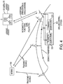
- Figure 4 shows one such alternative embodiment of a satellite system according to the invention.
- additional data on orbits of debris may be obtained from ground or space sources other than from tracking devices on the subject satellite. These data can be sent to the satellite through its ground control station 300 using its command subsystem 310 for use as a data augmentation to the satellite's generated tracking data. Also, if the satellite's orbital debris tracking subsystem fails and the remaining orbital avoidance subsystems are operable, the ground derived orbital debris locations/velocities can be used to continue normal satellite avoidance operations.
Landscapes
- Engineering & Computer Science (AREA)
- Remote Sensing (AREA)
- Radar, Positioning & Navigation (AREA)
- Physics & Mathematics (AREA)
- Aviation & Aerospace Engineering (AREA)
- General Physics & Mathematics (AREA)
- Computer Networks & Wireless Communication (AREA)
- Combustion & Propulsion (AREA)
- Chemical & Material Sciences (AREA)
- Astronomy & Astrophysics (AREA)
- Automation & Control Theory (AREA)
- Health & Medical Sciences (AREA)
- General Health & Medical Sciences (AREA)
- Electromagnetism (AREA)
- Artificial Intelligence (AREA)
- Evolutionary Computation (AREA)
- Medical Informatics (AREA)
- Robotics (AREA)
- Emergency Medicine (AREA)
- Critical Care (AREA)
- Control Of Position, Course, Altitude, Or Attitude Of Moving Bodies (AREA)
- Position Fixing By Use Of Radio Waves (AREA)
Claims (16)
- Satellitensystem (120), das autonom eine Kollision mit orbitalem Schrott (140) verhindern kann, enthaltend einen Satelliten (120), wobei der Satellit enthält:eine Orbitalschrott-Verfolgungsvorrichtung (101), die ausgebildet ist, Verfolgungsdaten über ein Schrottstück bereitzustellen;einen Umlaufbahnbestimmungsprozessor (102), der ausgebildet ist, die Verfolgungsdaten von der Orbitalschrott-Verfolgungsvorrichtung (101) zu empfangen und die Umlaufbahnen des Schrotts zu berechnen, Schrott-Umlaufbahnelementdaten zu erzeugen und die Umlaufbahnelemente des Satelliten (120) von Sensoren an Bord oder an Bord gespeicherten Daten oder beiden zu berechnen;einen Ephemeris-Prozessor (103), der ausgebildet ist, die Schrott-Umlaufbahnelementdaten und Satelliten-Umlaufbahnelementdaten vom Umlaufbahnbestimmungsprozessor zu empfangen und Ephemeris-Daten für zukünftige Positionen des Schrotts und zukünftige Positionen des Satelliten (120) zu berechnen;einen Kollisionsrechner (104), der ausgebildet ist, die zukünftigen Schrott-Ephemeris-Daten und die zukünftigen Satelliten-Ephemeris-Daten von dem Ephemeris-Prozessor (103) zu empfangen; wobei der Kollisionsrechner ausgebildet ist, die zukünftigen Satelliten- und Schrott-Ephemeris-Daten zu vergleichen; und eine Ausgangsschlussfolgerung bereitzustellen, wobei die Ausgangsschlussfolgerung zeigt, ob eine Kollision zu einem gewissen zukünftigen Zeitpunkt zwischen dem Schrott und dem Satelliten (120) stattfinden würde oder nicht;einen Ausweichumlaufbahnprozessor (108), der ausgebildet ist, die Ausgangsschlussfolgerung, dass wahrscheinlich eine Kollision stattfinden wird, zu empfangen und eine Ausweichumlaufbahn zu berechnen; undProzessoren (110) zum Erstellen von Antriebstriebwerksbefehlen, um die Ausweichumlaufbahn zu erreichen, und zum Ausführen der Befehle.
- Satellitensystem nach Anspruch 1, wobei die Orbitalverfolgungsvorrichtung (101) ausgewählt ist aus der Gruppe umfassend Radar, Ladar, Mikrowellenradar und optische oder Mikrowellenerkennung; und weiter umfassend einen Ausweichbefehlprozessor (109), der die Daten für eine Ausweichumlaufbahn vom Ausweichumlaufbahnprozessor (108) empfängt, die erforderlichen Befehle für die Triebwerkszündungen des Satelliten berechnet und veranlasst, dass diese Befehle ausgeführt werden, wobei die Orbitalverfolgungsvorrichtung (101) ausgebildet ist, eine vollständige Abdeckung des Spheroids um den Satelliten (120) bereitzustellen, um den Winkel, die Geschwindigkeit und den Bereich von Schrott vom Satelliten aus zu bestimmen.
- Satellitensystem nach Anspruch 2, wobei eine erste Umlaufbahnverfolgungsvorrichtung zum Verfolgen von Schrott mit einem Bereich hoher Geschwindigkeiten relativ zum Satelliten bereitgestellt ist und eine zweite Verfolgungsvorrichtung zum Verfolgen von Schrott mit einem Bereich geringer Geschwindigkeiten bereitgestellt ist.
- Satellitensystem nach Anspruch 2, wobei eine erste Verfolgungsvorrichtung (101) zum Verfolgen von Schrott mit einem Bereich großer Größen bereitgestellt ist und eine zweite Verfolgungsvorrichtung (101) zum Verfolgen von Schrott mit einem Bereich kleiner Größen bereitgestellt ist.
- Satellitensystem nach Anspruch 1, wobei der Ephemeris-Prozessor (103) ausgebildet ist, einen Teil der Schrott-Umlaufbahnelementdaten vom Umlaufbahnbestimmungsprozessor (102) zu empfangen und einen Teil der Satelliten-Umlaufbahnelementdaten von Sensoren an Bord oder an Bord gespeicherten Daten zu empfangen und wobei der Ephemeris-Prozessor (103) ausgebildet ist, einen Teil der Schrott-Umlaufbahnelementdaten von einer oder mehreren Bodenstationen (300) zu empfangen und einen Teil der Satelliten-Umlaufbahnelementdaten von einer oder mehreren Bodenstationen (300) zu empfangen.
- Satellitensystem nach Anspruch 1, wobei der Kollisionsrechner (104) eine Kollisionswahrscheinlichkeit für jedes Schrottstück (140) basierend auf einer Unsicherheit in Messungen, die mit den Umlaufbahn-, Größen- und Geschwindigkeitsdaten verknüpft sind, die mit dem Schrottstück (140) verknüpft sind, bestimmt.
- Satellitensystem nach Anspruch 1, wobei der Kollisionsrechner (104) weiter eine Ausgangsschlussfolgerung bereitstellt, die zeigt, ob eine Kollision zu einem gewissen zukünftigen Zeitpunkt zwischen einem Schrottstück und einer möglichen zukünftigen Position des Satelliten (120) stattfinden würde oder nicht, nachdem dieser ein Ausweichmanöver mit Umlaufbahnänderung ausgeführt hat.
- Satellitensystem nach Anspruch 1, wobei der Kollisionsrechner (104) eine Matrix von Umlaufbahnausweichmanöver-Auswahlmöglichkeiten für den Satelliten (120) führt, wobei jedes Matrixelement eine Risikobewertung einer Schrottkollision und die Menge an erforderlichem Treibstoff an Bord für jede Manöverauswahlmöglichkeit und die Betriebsleistung des Satelliten nach jedem möglichen Ausweichmanöver enthält.
- Satellitensystem nach Anspruch 1, wobei der Kollisionsrechner (104) ausgebildet ist zu bestimmen, ob eine Kollisionswahrscheinlichkeit mit orbitalem Schrott (140) unter einem vorbestimmten Schwellenwert liegt, und mindestens eine Schlussfolgerung bereitzustellen, enthaltend eine Ignorieren-Schlussfolgerung.
- Satellitensystem nach Anspruch 1, wobei der Satellitenausweichumlaufbahnprozessor (108) weiter ausgebildet ist, einen Lösungssatz von Umlaufbahnmanöverauswahlmöglichkeiten abhängig von einem oder mehreren Satellitenbetriebsleistungsparametern, die für jede Umlaufbahnmanöverauswahl vollkommen funktionell sind, aus einer Matrix zu wählen.
- Satellitensystem nach Anspruch 1, wobei der Satellitenausweichumlaufbahnprozessor (108) weiter ausgebildet ist, einen Lösungssatz von Umlaufbahnmanöverauswahlmöglichkeiten abhängig von einer Berechnung des minimalen Treibstoffs, der erforderlich ist, die neue Umlaufbahnausweichlösung zu erzielen, aus einer Matrix zu wählen.
- Satellitensystem nach Anspruch 1, wobei das System eine Schrottverfolgungsverweilzeit zum Durchführen von Berechnungen enthält, die mit einem oder mehreren Schrottstücken verknüpft sind, und Berechnungen priorisiert, die auf Position und Geschwindigkeit von Schrott beruhen.
- Satellitensystem nach Anspruch 9, wobei eine Satellitensystemvorrichtung, ausgewählt aus der Gruppe umfassend Orbitalschrott-Verfolgungsvorrichtung (101), Umlaufbahnbestimmungsprozessor (102), Kollisionsrechner (104) und Aktionsprozessor, ausgebildet ist, alle oder einen Teil der Daten, die mit einem ignorierten Objekt verknüpft sind, auf Basis der Ignorieren-Schlussfolgerung zu ignorieren.
- Satellitensystem nach Anspruch 1, wobei der Ephemeris-Prozessor (103) weiter ausgebildet ist, einen Teil der Schrott-Umlaufbahnelementdaten vom Umlaufbahnbestimmungsprozessor (102) zu empfangen und einen Teil der Satelliten-Umlaufbahnelementdaten vom Satellitencomputer zu empfangen, und wobei der Ephemeris-Prozessor (103) ausgebildet ist, einen Teil der Schrott-Umlaufbahnelementdaten von einer oder mehr Bodenstationen (300) zu empfangen und einen Teil der Satelliten-Umlaufbahnelementdaten von einer oder mehr Bodenstationen (300) zu empfangen.
- Satellitensystem nach Anspruch 1,
wobei die Verfolgungsdaten Ströme von Verfolgungsdaten über einzelne Schrottstücke (140) enthalten, die in der vollständigen sphärischen Hülle um den Satelliten (120) detektiert werden,
wobei die Schrott-Umlaufbahnelementdaten des Schrotts große Halbachse, Exzentrizität, Neigung, Rektakzension für den aufsteigenden Knoten, Argument des Perigäums, Periode, Zeit des Perigäums und deren Varianzen enthalten;
und wobei der Ausweichumlaufbahnprozessor (108) ausgebildet ist, einen Ausgang vom Kollisionsrechner (104) zu empfangen und eine minimale Änderung der bestehenden Umlaufbahn des Satelliten zu einer Umlaufbahn zu berechnen, die eine Kollision mit dem Schrott (140) vermeidet. - Satellitensystem nach Anspruch 15, wobei das Orbitalschrott-Verfolgungsmittel (101) eines oder mehrere der Gruppe, umfassend einen Radar und einen Ladar, ausgebildet, eine Abdeckung um den Satelliten bereitzustellen, zum Bestimmen des Winkels, der Geschwindigkeit und des Bereichs von Schrott vom Satelliten aus enthält.
Applications Claiming Priority (3)
| Application Number | Priority Date | Filing Date | Title |
|---|---|---|---|
| US201261688071P | 2012-05-07 | 2012-05-07 | |
| US13/986,059 US8833702B2 (en) | 2012-05-07 | 2013-03-27 | Autonomous satellite orbital debris avoidance system and method |
| PCT/US2013/000159 WO2013169309A2 (en) | 2012-05-07 | 2013-07-02 | Autonomous satellite orbital debris avoidance system and method |
Publications (3)
| Publication Number | Publication Date |
|---|---|
| EP2847747A2 EP2847747A2 (de) | 2015-03-18 |
| EP2847747A4 EP2847747A4 (de) | 2016-01-20 |
| EP2847747B1 true EP2847747B1 (de) | 2019-05-15 |
Family
ID=49511810
Family Applications (1)
| Application Number | Title | Priority Date | Filing Date |
|---|---|---|---|
| EP13787040.8A Active EP2847747B1 (de) | 2012-05-07 | 2013-07-02 | Autonomes system zur kollisionsverhinderung eines satelliten mt orbitalem schrott |
Country Status (7)
| Country | Link |
|---|---|
| US (1) | US8833702B2 (de) |
| EP (1) | EP2847747B1 (de) |
| CN (1) | CN104520914B (de) |
| CA (1) | CA2874532C (de) |
| ES (1) | ES2739834T3 (de) |
| RU (1) | RU2608899C2 (de) |
| WO (1) | WO2013169309A2 (de) |
Families Citing this family (47)
| Publication number | Priority date | Publication date | Assignee | Title |
|---|---|---|---|---|
| US9399527B2 (en) * | 2012-06-07 | 2016-07-26 | Electronics And Telecommunications Research Instit | Apparatus and method for controlling geostationary orbit satellite |
| US9484980B1 (en) * | 2012-12-03 | 2016-11-01 | Sprint Communications Company L.P. | Precision timing source back-up for loss of GPS satellites |
| KR101537301B1 (ko) * | 2013-10-28 | 2015-07-20 | 한국항공우주연구원 | Csm 기반 충돌위험 분석 시스템 |
| US9573702B1 (en) * | 2014-03-27 | 2017-02-21 | Lockheed Martin Corporation | Deployed radar panel for space situational awareness |
| US9989634B2 (en) * | 2014-04-22 | 2018-06-05 | Specialized Arrays, Inc. | System and method for detection and orbit determination of earth orbiting objects |
| US10293959B2 (en) * | 2015-07-28 | 2019-05-21 | Analytical Graphics Inc. | Probability and frequency of orbital encounters |
| WO2018016471A1 (ja) * | 2016-07-19 | 2018-01-25 | 三菱電機株式会社 | 人工衛星の自律運用計画システムおよび人工衛星の運用計画装置 |
| US10663974B2 (en) * | 2016-11-23 | 2020-05-26 | Electronics And Telecommunications Research Institute | Object recognition device, autonomous driving system including the same, and object recognition method using the object recognition device |
| CN106516174B (zh) * | 2016-12-02 | 2020-02-07 | 航天恒星科技有限公司 | 在轨航天器遭受空间碎片撞击监测方法及系统 |
| DE102017102481A1 (de) * | 2017-02-08 | 2018-08-09 | Klaus Schilling | Formationsfähiger Kleinstsatellit und Formation aus mehreren Kleinstsatelliten |
| CN107450312B (zh) * | 2017-07-06 | 2019-07-30 | 南京航空航天大学 | 考虑航天器尺寸的防碰撞方法 |
| CN107544332A (zh) * | 2017-09-14 | 2018-01-05 | 深圳市盛路物联通讯技术有限公司 | 数据处理方法及相关产品 |
| WO2020202221A1 (en) * | 2019-04-04 | 2020-10-08 | Lovely Professional University | A method and system for detecting and modeling objects in space using lidar |
| CN109991679B (zh) * | 2019-04-16 | 2021-05-07 | 上海微小卫星工程中心 | 空间碎片自感知系统及方法、卫星系统 |
| US11667407B2 (en) * | 2019-05-10 | 2023-06-06 | The Government Of The United States Of America, As Represented By The Secretary Of The Navy | System and method for automated intercept avoidance for spacecraft |
| US11782163B2 (en) | 2019-07-26 | 2023-10-10 | The Aerospace Corporation | Object detection and characterization using a LIDAR-based sensor |
| AU2021279256B2 (en) * | 2020-05-25 | 2023-04-06 | Airbus Defence And Space Sas | Method for estimating collision between at least one piece of space debris and a satellite |
| FR3110551B1 (fr) * | 2020-05-25 | 2022-06-03 | Airbus Defence & Space Sas | Procédé d’ajustement de trajectoire orbitale de satellite |
| JP2023532666A (ja) * | 2020-06-24 | 2023-07-31 | レオラボズ,インコーポレイテッド. | 軌道衝突スクリーニングのためのシステム及び方法 |
| CN114906353B (zh) * | 2020-09-29 | 2024-09-27 | 中国科学院微小卫星创新研究院 | 导航卫星空间态势感知方法 |
| CN112455724B (zh) * | 2020-11-24 | 2022-07-12 | 西北工业大学 | 一种基于投掷击打接取的空间被动物体转移方法 |
| CN112373730B (zh) * | 2020-12-09 | 2022-03-25 | 西北工业大学 | 一种卫星反绳网捕获的装置及方法 |
| WO2022192735A1 (en) * | 2021-03-11 | 2022-09-15 | Arizona Board Of Regents On Behalf Of The University Of Arizona | Satellite system with orbital debris avoidance |
| JP7773623B2 (ja) * | 2021-08-20 | 2025-11-19 | ヴィアサット,インコーポレイテッド | 低軌道衛星の追跡 |
| CN114030652B (zh) * | 2021-09-22 | 2023-09-12 | 北京电子工程总体研究所 | 一种避障路径规划方法和系统 |
| CN114506474B (zh) * | 2022-01-14 | 2023-08-18 | 上海卫星工程研究所 | 基于多类型遥感仪器联合探测的卫星布局 |
| WO2023141303A2 (en) * | 2022-01-21 | 2023-07-27 | Slingshot Aerospace, Inc. | Methods and systems for streaming buffer numerical propagation |
| FR3133932B1 (fr) * | 2022-03-24 | 2024-10-11 | Centre Nat Etd Spatiales | Procédé pour un contrôle d’orbite autonome et satellite configuré pour la mise en œuvre du procédé |
| CN114715436B (zh) * | 2022-03-30 | 2023-09-08 | 西安中科天塔科技股份有限公司 | 一种航天器碰撞预警方法、装置、控制设备及存储介质 |
| US11662183B1 (en) | 2022-09-13 | 2023-05-30 | Guardiansat, Llc | Systems and methods for automomous protection of satellites from hostile orbital attackers |
| CN115285381B (zh) * | 2022-10-09 | 2023-01-20 | 北京开运联合信息技术集团股份有限公司 | 一种太空碎片的碰撞预警方法及装置 |
| CN115664505B (zh) * | 2022-10-26 | 2024-06-18 | 中国科学院微小卫星创新研究院 | 大规模星座运维架构选择方法、装置和电子设备 |
| CN116002078A (zh) * | 2022-12-28 | 2023-04-25 | 上海航天控制技术研究所 | 一种非合作目标全自主防撞规避方法 |
| CN116331518B (zh) * | 2023-01-13 | 2023-09-26 | 天津大学 | 一种基于安全自适应动态规划的星群智能编队避碰控制方法 |
| US12286248B2 (en) | 2023-02-17 | 2025-04-29 | Southern Cross Outreach Observatory Project (SCOOP) | Space debris detection and mitigation with a network of deployed observatories |
| CN117048853B (zh) * | 2023-08-29 | 2024-01-23 | 北京航天驭星科技有限公司 | 采用电推方式调整轨控的方法、系统、电子设备、介质 |
| US12552553B2 (en) * | 2023-10-30 | 2026-02-17 | International Business Machines Corporation | Crowdsource satellite network |
| US20250153866A1 (en) * | 2023-11-14 | 2025-05-15 | Momentus Space Llc | Systems and Methods for Maintenance of a Spacecraft Constellation |
| CN117228008B (zh) * | 2023-11-15 | 2024-02-02 | 北京开运联合信息技术集团股份有限公司 | 基于太空目标数据的航天器碰撞预警方法及存储介质 |
| US12028654B1 (en) | 2023-11-27 | 2024-07-02 | NorthStar Earth & Space Inc. | System and method for generating a plurality of celestial image features from a plurality of images of a sky |
| US12249055B1 (en) | 2024-06-12 | 2025-03-11 | NorthStar Earth & Space Inc. | System for generating and processing a plurality of celestial image features from a plurality of images of a sky and methods of use thereof |
| CN118169678A (zh) * | 2024-05-14 | 2024-06-11 | 电子科技大学 | 一种基于毫米波雷达的卫星来袭异物检测方法和系统 |
| DE102024125429A1 (de) * | 2024-09-05 | 2026-03-05 | Vyoma GmbH | Satellitensystem und computerimplementiertes Verfahren zur Überwachung und Erkennung von Weltraumobjekten im himmelskörpernahen Weltraum, System zur Datenverarbeitung, Computerprogramm und computerlesbares Medium |
| DE102024125428A1 (de) * | 2024-09-05 | 2026-03-05 | Vyoma GmbH | Satellitensystem und computerimplementiertes Verfahren zur Überwachung und Erkennung von Weltraumobjekten im himmelskörpernahen Weltraum, System zur Datenverarbeitung, Computerprogramm und computerlesbares Medium |
| CN119668296B (zh) * | 2025-02-20 | 2025-05-16 | 北京航空航天大学 | 运载火箭碎片规避管道-轨迹一体规划方法、设备及介质 |
| CN119995694B (zh) * | 2025-04-14 | 2025-07-01 | 烟台中飞海装科技有限公司 | 一种用于低轨卫星的故障分析方法 |
| CN121671910B (zh) * | 2026-02-10 | 2026-04-21 | 上海太驿微行航天科技有限公司 | 一种空间碎片轨道预测与规避方法 |
Family Cites Families (22)
| Publication number | Priority date | Publication date | Assignee | Title |
|---|---|---|---|---|
| US5120008A (en) * | 1989-07-28 | 1992-06-09 | Kumar Ramohalli | Orbital debris processor and method therefor |
| DE3943374A1 (de) | 1989-12-30 | 1991-07-04 | Deutsche Forsch Luft Raumfahrt | Verfahren und einrichtung zum entfernen von weltraumtruemmern |
| US4991799A (en) | 1990-02-16 | 1991-02-12 | The United States Of America As Represented By The Administrator Of The National Aeronautics And Space Administration | Orbital debris sweeper and method |
| JPH0789497A (ja) * | 1993-09-24 | 1995-04-04 | Nec Corp | 自動衝突回避装置及び自動衝突回避装置付人工衛星 |
| JP3867315B2 (ja) * | 1996-04-22 | 2007-01-10 | 三菱電機株式会社 | 自動衝突回避装置 |
| RU2137682C1 (ru) * | 1996-12-25 | 1999-09-20 | Гуров Александр Ефимович | Способ увеличения сроков активного существования космических аппаратов |
| JP2879146B1 (ja) * | 1998-03-23 | 1999-04-05 | 宇宙開発事業団 | 複数人工衛星による運動物体の位置決定システム |
| US6142423A (en) * | 1999-06-29 | 2000-11-07 | Trw Inc. | Ephemeris/attitude reference determination using on-board optics and other satellite ephemeris |
| US6667713B2 (en) | 2001-08-24 | 2003-12-23 | Spectrum Astro | Self-monitoring satellite system |
| WO2003067278A2 (en) * | 2002-02-08 | 2003-08-14 | Lockheed Martin Corporation | System and method for doppler track correlation for debris tracking |
| JP3965385B2 (ja) * | 2003-12-24 | 2007-08-29 | 株式会社日立製作所 | Dvd記録方法及びdvd記録装置 |
| US7551121B1 (en) | 2004-03-12 | 2009-06-23 | Oceanit Laboratories, Inc. | Multi-target-tracking optical sensor-array technology |
| US7105791B1 (en) * | 2004-10-20 | 2006-09-12 | Brian Poller | Orbital debris detection and tracking system utilizing sun or moon occlusion |
| US7437246B2 (en) * | 2006-08-01 | 2008-10-14 | Raytheon Company | Method of determining a collision avoidance maneuver |
| US8412391B2 (en) | 2007-08-17 | 2013-04-02 | Princeton Satelitte Systems | Proximity spacecraft maneuvering |
| US8041509B2 (en) | 2008-08-19 | 2011-10-18 | Analytical Graphics, Inc. | System and method of addressing nonlinear relative motion for collision probability using parallelepipeds |
| US20100250137A1 (en) * | 2009-03-25 | 2010-09-30 | Hoots Felix R | Analytic Launch Collision Avoidance Methodology |
| US8386099B2 (en) * | 2010-02-05 | 2013-02-26 | Applied Defense Solutions | Method and apparatus for initial orbit determination using high-precision orbit propagation and maneuver modeling |
| US20120016541A1 (en) * | 2010-07-16 | 2012-01-19 | Salvatore Alfano | System and Method for Assessing the Risk of Conjunction of a Rocket Body with Orbiting and Non-Orbiting Platforms |
| US8275498B2 (en) * | 2010-07-16 | 2012-09-25 | Analytical Graphics Inc. | System and method for assessing the risk of conjunction of a rocket body with orbiting and non-orbiting platforms |
| US8567725B2 (en) * | 2010-09-16 | 2013-10-29 | Raytheon Company | Orbital debris mitigation system and method |
| FR2979736B1 (fr) * | 2011-09-05 | 2013-08-30 | Centre Nat Etd Spatiales | Procede de detection de messages sia |
-
2013
- 2013-03-27 US US13/986,059 patent/US8833702B2/en active Active
- 2013-07-02 CN CN201380028997.5A patent/CN104520914B/zh active Active
- 2013-07-02 EP EP13787040.8A patent/EP2847747B1/de active Active
- 2013-07-02 CA CA2874532A patent/CA2874532C/en active Active
- 2013-07-02 WO PCT/US2013/000159 patent/WO2013169309A2/en not_active Ceased
- 2013-07-02 RU RU2014149098A patent/RU2608899C2/ru active
- 2013-07-02 ES ES13787040T patent/ES2739834T3/es active Active
Non-Patent Citations (1)
| Title |
|---|
| None * |
Also Published As
| Publication number | Publication date |
|---|---|
| EP2847747A4 (de) | 2016-01-20 |
| US8833702B2 (en) | 2014-09-16 |
| CN104520914A (zh) | 2015-04-15 |
| ES2739834T3 (es) | 2020-02-04 |
| CN104520914B (zh) | 2016-10-26 |
| WO2013169309A2 (en) | 2013-11-14 |
| EP2847747A2 (de) | 2015-03-18 |
| RU2014149098A (ru) | 2016-06-27 |
| CA2874532A1 (en) | 2013-11-14 |
| WO2013169309A3 (en) | 2014-02-27 |
| CA2874532C (en) | 2018-09-11 |
| RU2608899C2 (ru) | 2017-01-26 |
| US20130292517A1 (en) | 2013-11-07 |
Similar Documents
| Publication | Publication Date | Title |
|---|---|---|
| EP2847747B1 (de) | Autonomes system zur kollisionsverhinderung eines satelliten mt orbitalem schrott | |
| US20180346153A1 (en) | Apparatus and Methods for Orbital Sensing and Debris Removal | |
| JP7479555B2 (ja) | 衝突回避方法および地上設備 | |
| US12473102B2 (en) | Satellite system with orbital debris avoidance | |
| WO2022137623A1 (ja) | 衛星コンステレーション、飛翔体対処システム、情報収集システム、衛星情報伝送システム、衛星、ハイブリッドコンステレーション、ハイブリッドコンステレーション形成方法、地上システム、ミッション衛星、および、地上設備 | |
| US10543939B2 (en) | Apparatus and methods for creating artificial near-earth orbits | |
| Frauenholz et al. | Deep impact navigation system performance | |
| JP2024003118A (ja) | 観測システム、通信衛星、観測衛星および地上設備 | |
| Kahle | Flight dynamics operations of the TanDEM-X formation | |
| Machula et al. | Rendezvous and docking for space exploration | |
| Lee et al. | Preliminary design of the guidance, navigation, and control system of the altair lunar lander | |
| US20240124161A1 (en) | Flight path model selection method, flying object tracking system, flying object handling system, and ground system | |
| Wermuth et al. | Operational Concept of a Picosatellite Release from a LEO Satellite | |
| Nimelman et al. | Spaceborne scanning lidar system (SSLS) upgrade path | |
| Collins et al. | MANS-Autonomous navigation and orbit control for communications satellites | |
| US12250059B1 (en) | System and method for GEO/GSO object mapping and modeling | |
| Schulze et al. | The operations concept for tandem-l–from mission goals to spacecraft requirements | |
| JP7504281B2 (ja) | 飛翔位置導出方法、飛翔体追跡システム、地上システムおよび飛翔体対処システム | |
| Mongrard et al. | ATV GNC flight performance and lessons learned | |
| Di Corato et al. | Design of a Robust Low-Thrust Orbit Raising Strategy for MEO Constellation Deployment | |
| Gaura et al. | Recommended Satellite Network based Autonomous Navigation for Martian Lander | |
| Herman et al. | AOCS for Tandem-X Formation Flight at 150m Separation in Low-Earth Orbit | |
| Riot et al. | The Space-based Telescopes for Actionable Refinement of Ephemeris (STARE) mission | |
| Schulze | Formation flight in low-earth-orbit at 150 m distance-AOCS in-orbit experience | |
| Lin | An Orbital Debris Active Protection System for Space Stations in Low Earth Orbit |
Legal Events
| Date | Code | Title | Description |
|---|---|---|---|
| PUAI | Public reference made under article 153(3) epc to a published international application that has entered the european phase |
Free format text: ORIGINAL CODE: 0009012 |
|
| 17P | Request for examination filed |
Effective date: 20141125 |
|
| AK | Designated contracting states |
Kind code of ref document: A2 Designated state(s): AL AT BE BG CH CY CZ DE DK EE ES FI FR GB GR HR HU IE IS IT LI LT LU LV MC MK MT NL NO PL PT RO RS SE SI SK SM TR |
|
| AX | Request for extension of the european patent |
Extension state: BA ME |
|
| DAX | Request for extension of the european patent (deleted) | ||
| A4 | Supplementary search report drawn up and despatched |
Effective date: 20151223 |
|
| RIC1 | Information provided on ipc code assigned before grant |
Ipc: G01S 13/72 20060101ALI20151217BHEP Ipc: B64G 1/10 20060101ALI20151217BHEP Ipc: B64G 1/66 20060101ALI20151217BHEP Ipc: G01S 13/93 20060101ALI20151217BHEP Ipc: B64G 3/00 20060101ALI20151217BHEP Ipc: G08G 5/04 20060101AFI20151217BHEP Ipc: B64G 1/24 20060101ALI20151217BHEP Ipc: G01S 13/87 20060101ALI20151217BHEP Ipc: G01S 7/00 20060101ALI20151217BHEP |
|
| GRAP | Despatch of communication of intention to grant a patent |
Free format text: ORIGINAL CODE: EPIDOSNIGR1 |
|
| STAA | Information on the status of an ep patent application or granted ep patent |
Free format text: STATUS: GRANT OF PATENT IS INTENDED |
|
| INTG | Intention to grant announced |
Effective date: 20181203 |
|
| GRAS | Grant fee paid |
Free format text: ORIGINAL CODE: EPIDOSNIGR3 |
|
| GRAA | (expected) grant |
Free format text: ORIGINAL CODE: 0009210 |
|
| STAA | Information on the status of an ep patent application or granted ep patent |
Free format text: STATUS: THE PATENT HAS BEEN GRANTED |
|
| AK | Designated contracting states |
Kind code of ref document: B1 Designated state(s): AL AT BE BG CH CY CZ DE DK EE ES FI FR GB GR HR HU IE IS IT LI LT LU LV MC MK MT NL NO PL PT RO RS SE SI SK SM TR |
|
| REG | Reference to a national code |
Ref country code: CH Ref legal event code: EP |
|
| REG | Reference to a national code |
Ref country code: IE Ref legal event code: FG4D |
|
| REG | Reference to a national code |
Ref country code: DE Ref legal event code: R096 Ref document number: 602013055477 Country of ref document: DE |
|
| REG | Reference to a national code |
Ref country code: NL Ref legal event code: MP Effective date: 20190515 |
|
| REG | Reference to a national code |
Ref country code: LT Ref legal event code: MG4D |
|
| PG25 | Lapsed in a contracting state [announced via postgrant information from national office to epo] |
Ref country code: FI Free format text: LAPSE BECAUSE OF FAILURE TO SUBMIT A TRANSLATION OF THE DESCRIPTION OR TO PAY THE FEE WITHIN THE PRESCRIBED TIME-LIMIT Effective date: 20190515 Ref country code: NO Free format text: LAPSE BECAUSE OF FAILURE TO SUBMIT A TRANSLATION OF THE DESCRIPTION OR TO PAY THE FEE WITHIN THE PRESCRIBED TIME-LIMIT Effective date: 20190815 Ref country code: PT Free format text: LAPSE BECAUSE OF FAILURE TO SUBMIT A TRANSLATION OF THE DESCRIPTION OR TO PAY THE FEE WITHIN THE PRESCRIBED TIME-LIMIT Effective date: 20190915 Ref country code: SE Free format text: LAPSE BECAUSE OF FAILURE TO SUBMIT A TRANSLATION OF THE DESCRIPTION OR TO PAY THE FEE WITHIN THE PRESCRIBED TIME-LIMIT Effective date: 20190515 Ref country code: AL Free format text: LAPSE BECAUSE OF FAILURE TO SUBMIT A TRANSLATION OF THE DESCRIPTION OR TO PAY THE FEE WITHIN THE PRESCRIBED TIME-LIMIT Effective date: 20190515 Ref country code: HR Free format text: LAPSE BECAUSE OF FAILURE TO SUBMIT A TRANSLATION OF THE DESCRIPTION OR TO PAY THE FEE WITHIN THE PRESCRIBED TIME-LIMIT Effective date: 20190515 Ref country code: LT Free format text: LAPSE BECAUSE OF FAILURE TO SUBMIT A TRANSLATION OF THE DESCRIPTION OR TO PAY THE FEE WITHIN THE PRESCRIBED TIME-LIMIT Effective date: 20190515 Ref country code: NL Free format text: LAPSE BECAUSE OF FAILURE TO SUBMIT A TRANSLATION OF THE DESCRIPTION OR TO PAY THE FEE WITHIN THE PRESCRIBED TIME-LIMIT Effective date: 20190515 |
|
| PG25 | Lapsed in a contracting state [announced via postgrant information from national office to epo] |
Ref country code: RS Free format text: LAPSE BECAUSE OF FAILURE TO SUBMIT A TRANSLATION OF THE DESCRIPTION OR TO PAY THE FEE WITHIN THE PRESCRIBED TIME-LIMIT Effective date: 20190515 Ref country code: BG Free format text: LAPSE BECAUSE OF FAILURE TO SUBMIT A TRANSLATION OF THE DESCRIPTION OR TO PAY THE FEE WITHIN THE PRESCRIBED TIME-LIMIT Effective date: 20190815 Ref country code: GR Free format text: LAPSE BECAUSE OF FAILURE TO SUBMIT A TRANSLATION OF THE DESCRIPTION OR TO PAY THE FEE WITHIN THE PRESCRIBED TIME-LIMIT Effective date: 20190816 Ref country code: LV Free format text: LAPSE BECAUSE OF FAILURE TO SUBMIT A TRANSLATION OF THE DESCRIPTION OR TO PAY THE FEE WITHIN THE PRESCRIBED TIME-LIMIT Effective date: 20190515 |
|
| REG | Reference to a national code |
Ref country code: AT Ref legal event code: MK05 Ref document number: 1134349 Country of ref document: AT Kind code of ref document: T Effective date: 20190515 |
|
| PG25 | Lapsed in a contracting state [announced via postgrant information from national office to epo] |
Ref country code: RO Free format text: LAPSE BECAUSE OF FAILURE TO SUBMIT A TRANSLATION OF THE DESCRIPTION OR TO PAY THE FEE WITHIN THE PRESCRIBED TIME-LIMIT Effective date: 20190515 Ref country code: SK Free format text: LAPSE BECAUSE OF FAILURE TO SUBMIT A TRANSLATION OF THE DESCRIPTION OR TO PAY THE FEE WITHIN THE PRESCRIBED TIME-LIMIT Effective date: 20190515 Ref country code: CZ Free format text: LAPSE BECAUSE OF FAILURE TO SUBMIT A TRANSLATION OF THE DESCRIPTION OR TO PAY THE FEE WITHIN THE PRESCRIBED TIME-LIMIT Effective date: 20190515 Ref country code: EE Free format text: LAPSE BECAUSE OF FAILURE TO SUBMIT A TRANSLATION OF THE DESCRIPTION OR TO PAY THE FEE WITHIN THE PRESCRIBED TIME-LIMIT Effective date: 20190515 Ref country code: AT Free format text: LAPSE BECAUSE OF FAILURE TO SUBMIT A TRANSLATION OF THE DESCRIPTION OR TO PAY THE FEE WITHIN THE PRESCRIBED TIME-LIMIT Effective date: 20190515 Ref country code: DK Free format text: LAPSE BECAUSE OF FAILURE TO SUBMIT A TRANSLATION OF THE DESCRIPTION OR TO PAY THE FEE WITHIN THE PRESCRIBED TIME-LIMIT Effective date: 20190515 |
|
| REG | Reference to a national code |
Ref country code: ES Ref legal event code: FG2A Ref document number: 2739834 Country of ref document: ES Kind code of ref document: T3 Effective date: 20200204 |
|
| REG | Reference to a national code |
Ref country code: DE Ref legal event code: R097 Ref document number: 602013055477 Country of ref document: DE |
|
| PG25 | Lapsed in a contracting state [announced via postgrant information from national office to epo] |
Ref country code: SM Free format text: LAPSE BECAUSE OF FAILURE TO SUBMIT A TRANSLATION OF THE DESCRIPTION OR TO PAY THE FEE WITHIN THE PRESCRIBED TIME-LIMIT Effective date: 20190515 Ref country code: MC Free format text: LAPSE BECAUSE OF FAILURE TO SUBMIT A TRANSLATION OF THE DESCRIPTION OR TO PAY THE FEE WITHIN THE PRESCRIBED TIME-LIMIT Effective date: 20190515 |
|
| REG | Reference to a national code |
Ref country code: CH Ref legal event code: PL |
|
| PLBE | No opposition filed within time limit |
Free format text: ORIGINAL CODE: 0009261 |
|
| STAA | Information on the status of an ep patent application or granted ep patent |
Free format text: STATUS: NO OPPOSITION FILED WITHIN TIME LIMIT |
|
| PG25 | Lapsed in a contracting state [announced via postgrant information from national office to epo] |
Ref country code: TR Free format text: LAPSE BECAUSE OF FAILURE TO SUBMIT A TRANSLATION OF THE DESCRIPTION OR TO PAY THE FEE WITHIN THE PRESCRIBED TIME-LIMIT Effective date: 20190515 |
|
| REG | Reference to a national code |
Ref country code: BE Ref legal event code: MM Effective date: 20190731 |
|
| 26N | No opposition filed |
Effective date: 20200218 |
|
| PG25 | Lapsed in a contracting state [announced via postgrant information from national office to epo] |
Ref country code: PL Free format text: LAPSE BECAUSE OF FAILURE TO SUBMIT A TRANSLATION OF THE DESCRIPTION OR TO PAY THE FEE WITHIN THE PRESCRIBED TIME-LIMIT Effective date: 20190515 |
|
| PG25 | Lapsed in a contracting state [announced via postgrant information from national office to epo] |
Ref country code: CH Free format text: LAPSE BECAUSE OF NON-PAYMENT OF DUE FEES Effective date: 20190731 Ref country code: LU Free format text: LAPSE BECAUSE OF NON-PAYMENT OF DUE FEES Effective date: 20190702 Ref country code: BE Free format text: LAPSE BECAUSE OF NON-PAYMENT OF DUE FEES Effective date: 20190731 Ref country code: SI Free format text: LAPSE BECAUSE OF FAILURE TO SUBMIT A TRANSLATION OF THE DESCRIPTION OR TO PAY THE FEE WITHIN THE PRESCRIBED TIME-LIMIT Effective date: 20190515 Ref country code: LI Free format text: LAPSE BECAUSE OF NON-PAYMENT OF DUE FEES Effective date: 20190731 |
|
| PG25 | Lapsed in a contracting state [announced via postgrant information from national office to epo] |
Ref country code: IE Free format text: LAPSE BECAUSE OF NON-PAYMENT OF DUE FEES Effective date: 20190702 |
|
| PG25 | Lapsed in a contracting state [announced via postgrant information from national office to epo] |
Ref country code: CY Free format text: LAPSE BECAUSE OF FAILURE TO SUBMIT A TRANSLATION OF THE DESCRIPTION OR TO PAY THE FEE WITHIN THE PRESCRIBED TIME-LIMIT Effective date: 20190515 |
|
| PG25 | Lapsed in a contracting state [announced via postgrant information from national office to epo] |
Ref country code: IS Free format text: LAPSE BECAUSE OF FAILURE TO SUBMIT A TRANSLATION OF THE DESCRIPTION OR TO PAY THE FEE WITHIN THE PRESCRIBED TIME-LIMIT Effective date: 20190915 |
|
| PG25 | Lapsed in a contracting state [announced via postgrant information from national office to epo] |
Ref country code: MT Free format text: LAPSE BECAUSE OF FAILURE TO SUBMIT A TRANSLATION OF THE DESCRIPTION OR TO PAY THE FEE WITHIN THE PRESCRIBED TIME-LIMIT Effective date: 20190515 Ref country code: HU Free format text: LAPSE BECAUSE OF FAILURE TO SUBMIT A TRANSLATION OF THE DESCRIPTION OR TO PAY THE FEE WITHIN THE PRESCRIBED TIME-LIMIT; INVALID AB INITIO Effective date: 20130702 |
|
| PG25 | Lapsed in a contracting state [announced via postgrant information from national office to epo] |
Ref country code: MK Free format text: LAPSE BECAUSE OF FAILURE TO SUBMIT A TRANSLATION OF THE DESCRIPTION OR TO PAY THE FEE WITHIN THE PRESCRIBED TIME-LIMIT Effective date: 20190515 |
|
| REG | Reference to a national code |
Ref country code: DE Ref legal event code: R079 Ref document number: 602013055477 Country of ref document: DE Free format text: PREVIOUS MAIN CLASS: G08G0005040000 Ipc: G08G0005800000 |
|
| PGFP | Annual fee paid to national office [announced via postgrant information from national office to epo] |
Ref country code: ES Payment date: 20250819 Year of fee payment: 13 |
|
| PGFP | Annual fee paid to national office [announced via postgrant information from national office to epo] |
Ref country code: DE Payment date: 20250722 Year of fee payment: 13 |
|
| PGFP | Annual fee paid to national office [announced via postgrant information from national office to epo] |
Ref country code: IT Payment date: 20250731 Year of fee payment: 13 |
|
| PGFP | Annual fee paid to national office [announced via postgrant information from national office to epo] |
Ref country code: GB Payment date: 20250724 Year of fee payment: 13 |
|
| PGFP | Annual fee paid to national office [announced via postgrant information from national office to epo] |
Ref country code: FR Payment date: 20250723 Year of fee payment: 13 |