EP2847123B1 - Filling machine - Google Patents
Filling machine Download PDFInfo
- Publication number
- EP2847123B1 EP2847123B1 EP13715130.4A EP13715130A EP2847123B1 EP 2847123 B1 EP2847123 B1 EP 2847123B1 EP 13715130 A EP13715130 A EP 13715130A EP 2847123 B1 EP2847123 B1 EP 2847123B1
- Authority
- EP
- European Patent Office
- Prior art keywords
- filling
- flushing
- axis
- machine according
- caps
- Prior art date
- Legal status (The legal status is an assumption and is not a legal conclusion. Google has not performed a legal analysis and makes no representation as to the accuracy of the status listed.)
- Active
Links
- 238000011049 filling Methods 0.000 title claims description 127
- 238000011010 flushing procedure Methods 0.000 claims description 36
- 238000004140 cleaning Methods 0.000 claims description 32
- 238000004659 sterilization and disinfection Methods 0.000 claims description 22
- 239000012530 fluid Substances 0.000 claims description 9
- 238000004806 packaging method and process Methods 0.000 claims description 8
- 238000007789 sealing Methods 0.000 claims description 5
- 230000007704 transition Effects 0.000 claims description 2
- 238000012371 Aseptic Filling Methods 0.000 claims 1
- 239000012212 insulator Substances 0.000 description 21
- 230000001954 sterilising effect Effects 0.000 description 19
- 239000000945 filler Substances 0.000 description 18
- 239000007788 liquid Substances 0.000 description 13
- 239000000463 material Substances 0.000 description 5
- 230000008901 benefit Effects 0.000 description 3
- 238000005429 filling process Methods 0.000 description 3
- 239000012263 liquid product Substances 0.000 description 3
- 238000000034 method Methods 0.000 description 3
- 239000005022 packaging material Substances 0.000 description 3
- 239000003206 sterilizing agent Substances 0.000 description 3
- 239000000969 carrier Substances 0.000 description 2
- 230000000249 desinfective effect Effects 0.000 description 2
- 238000007599 discharging Methods 0.000 description 2
- 238000004519 manufacturing process Methods 0.000 description 2
- 230000004048 modification Effects 0.000 description 2
- 238000012986 modification Methods 0.000 description 2
- 230000008569 process Effects 0.000 description 2
- 239000000047 product Substances 0.000 description 2
- 230000002421 anti-septic effect Effects 0.000 description 1
- POIUWJQBRNEFGX-XAMSXPGMSA-N cathelicidin Chemical compound C([C@@H](C(=O)N[C@@H](CCCNC(N)=N)C(=O)N[C@@H](CCCCN)C(=O)N[C@@H](CO)C(=O)N[C@@H](CCCCN)C(=O)N[C@@H](CCC(O)=O)C(=O)N[C@@H](CCCCN)C(=O)N[C@@H]([C@@H](C)CC)C(=O)NCC(=O)N[C@@H](CCCCN)C(=O)N[C@@H](CCC(O)=O)C(=O)N[C@@H](CC=1C=CC=CC=1)C(=O)N[C@@H](CCCCN)C(=O)N[C@@H](CCCNC(N)=N)C(=O)N[C@@H]([C@@H](C)CC)C(=O)N[C@@H](C(C)C)C(=O)N[C@@H](CCC(N)=O)C(=O)N[C@@H](CCCNC(N)=N)C(=O)N[C@@H]([C@@H](C)CC)C(=O)N[C@@H](CCCCN)C(=O)N[C@@H](CC(O)=O)C(=O)N[C@@H](CC=1C=CC=CC=1)C(=O)N[C@@H](CC(C)C)C(=O)N[C@@H](CCCNC(N)=N)C(=O)N[C@@H](CC(N)=O)C(=O)N[C@@H](CC(C)C)C(=O)N[C@@H](C(C)C)C(=O)N1[C@@H](CCC1)C(=O)N[C@@H](CCCNC(N)=N)C(=O)N[C@@H]([C@@H](C)O)C(=O)N[C@@H](CCC(O)=O)C(=O)N[C@@H](CO)C(O)=O)NC(=O)[C@H](CC=1C=CC=CC=1)NC(=O)[C@H](CC(O)=O)NC(=O)CNC(=O)[C@H](CC(C)C)NC(=O)[C@@H](N)CC(C)C)C1=CC=CC=C1 POIUWJQBRNEFGX-XAMSXPGMSA-N 0.000 description 1
- 239000003795 chemical substances by application Substances 0.000 description 1
- 238000010276 construction Methods 0.000 description 1
- 238000011109 contamination Methods 0.000 description 1
- 230000008878 coupling Effects 0.000 description 1
- 238000010168 coupling process Methods 0.000 description 1
- 238000005859 coupling reaction Methods 0.000 description 1
- 238000011161 development Methods 0.000 description 1
- 230000018109 developmental process Effects 0.000 description 1
- 239000011521 glass Substances 0.000 description 1
- 239000004615 ingredient Substances 0.000 description 1
- 239000002184 metal Substances 0.000 description 1
- NJPPVKZQTLUDBO-UHFFFAOYSA-N novaluron Chemical compound C1=C(Cl)C(OC(F)(F)C(OC(F)(F)F)F)=CC=C1NC(=O)NC(=O)C1=C(F)C=CC=C1F NJPPVKZQTLUDBO-UHFFFAOYSA-N 0.000 description 1
- 230000002093 peripheral effect Effects 0.000 description 1
- 239000004033 plastic Substances 0.000 description 1
- 230000000284 resting effect Effects 0.000 description 1
- 230000002000 scavenging effect Effects 0.000 description 1
- 238000005406 washing Methods 0.000 description 1
- XLYOFNOQVPJJNP-UHFFFAOYSA-N water Chemical compound O XLYOFNOQVPJJNP-UHFFFAOYSA-N 0.000 description 1
Images


Classifications
-
- B—PERFORMING OPERATIONS; TRANSPORTING
- B67—OPENING, CLOSING OR CLEANING BOTTLES, JARS OR SIMILAR CONTAINERS; LIQUID HANDLING
- B67C—CLEANING, FILLING WITH LIQUIDS OR SEMILIQUIDS, OR EMPTYING, OF BOTTLES, JARS, CANS, CASKS, BARRELS, OR SIMILAR CONTAINERS, NOT OTHERWISE PROVIDED FOR; FUNNELS
- B67C7/00—Concurrent cleaning, filling, and closing of bottles; Processes or devices for at least two of these operations
- B67C7/0006—Conveying; Synchronising
- B67C7/004—Conveying; Synchronising the containers travelling along a circular path
- B67C7/0046—Infeed and outfeed devices
-
- B—PERFORMING OPERATIONS; TRANSPORTING
- B67—OPENING, CLOSING OR CLEANING BOTTLES, JARS OR SIMILAR CONTAINERS; LIQUID HANDLING
- B67C—CLEANING, FILLING WITH LIQUIDS OR SEMILIQUIDS, OR EMPTYING, OF BOTTLES, JARS, CANS, CASKS, BARRELS, OR SIMILAR CONTAINERS, NOT OTHERWISE PROVIDED FOR; FUNNELS
- B67C3/00—Bottling liquids or semiliquids; Filling jars or cans with liquids or semiliquids using bottling or like apparatus; Filling casks or barrels with liquids or semiliquids
- B67C3/001—Cleaning of filling devices
- B67C3/002—Cleaning of filling devices using cups or dummies to be placed under the filling heads
- B67C3/004—Cleaning of filling devices using cups or dummies to be placed under the filling heads permanently attached to the filling machine and movable between a rest and a working position
-
- B—PERFORMING OPERATIONS; TRANSPORTING
- B67—OPENING, CLOSING OR CLEANING BOTTLES, JARS OR SIMILAR CONTAINERS; LIQUID HANDLING
- B67C—CLEANING, FILLING WITH LIQUIDS OR SEMILIQUIDS, OR EMPTYING, OF BOTTLES, JARS, CANS, CASKS, BARRELS, OR SIMILAR CONTAINERS, NOT OTHERWISE PROVIDED FOR; FUNNELS
- B67C3/00—Bottling liquids or semiliquids; Filling jars or cans with liquids or semiliquids using bottling or like apparatus; Filling casks or barrels with liquids or semiliquids
- B67C3/02—Bottling liquids or semiliquids; Filling jars or cans with liquids or semiliquids using bottling or like apparatus
- B67C3/06—Bottling liquids or semiliquids; Filling jars or cans with liquids or semiliquids using bottling or like apparatus using counterpressure, i.e. filling while the container is under pressure
-
- B—PERFORMING OPERATIONS; TRANSPORTING
- B67—OPENING, CLOSING OR CLEANING BOTTLES, JARS OR SIMILAR CONTAINERS; LIQUID HANDLING
- B67C—CLEANING, FILLING WITH LIQUIDS OR SEMILIQUIDS, OR EMPTYING, OF BOTTLES, JARS, CANS, CASKS, BARRELS, OR SIMILAR CONTAINERS, NOT OTHERWISE PROVIDED FOR; FUNNELS
- B67C3/00—Bottling liquids or semiliquids; Filling jars or cans with liquids or semiliquids using bottling or like apparatus; Filling casks or barrels with liquids or semiliquids
- B67C3/02—Bottling liquids or semiliquids; Filling jars or cans with liquids or semiliquids using bottling or like apparatus
- B67C3/22—Details
- B67C2003/228—Aseptic features
-
- B—PERFORMING OPERATIONS; TRANSPORTING
- B67—OPENING, CLOSING OR CLEANING BOTTLES, JARS OR SIMILAR CONTAINERS; LIQUID HANDLING
- B67C—CLEANING, FILLING WITH LIQUIDS OR SEMILIQUIDS, OR EMPTYING, OF BOTTLES, JARS, CANS, CASKS, BARRELS, OR SIMILAR CONTAINERS, NOT OTHERWISE PROVIDED FOR; FUNNELS
- B67C7/00—Concurrent cleaning, filling, and closing of bottles; Processes or devices for at least two of these operations
- B67C7/0006—Conveying; Synchronising
- B67C2007/006—Devices particularly adapted for container filling
Definitions
- the invention relates to a filling machine according to the preamble of patent claim 1, and as shown in WO 2007/019590 A2 known.
- Filling machines for filling of packaging materials, in particular bottles or similar containers, with a liquid product are known in numerous designs. In this case, it is also known, in particular, to provide flushing caps with a return channel for the medium used for rinsing, cleaning and / or disinfecting on the circulating transport element or rotor of the filling machine ( DE 10 2004 004 331 ).
- flushing caps one of which is associated with a filling element are by pivoting or extending from a starting position in which they are located during the filling outside the filling elements and the container to be filled, in a working position in which each flushing cap in sealing position against the associated filling element is brought and then forms an at least the dispensing opening of the filling element enclosing outwardly closed washing compartment or flushing channel during cleaning and / or disinfection, especially during a CIP cleaning and / or disinfection of the liquid and / or gas and / or vapor cleaning and / or sterilizing medium is flowed through.
- the arrangement of the Spülkappen the revolving transport element there is also a constructive freedom restricting very dense construction, which is not desirable in many cases.
- filling machines of peripheral design for an antiseptic filling of packaging materials such as bottles or other containers with a liquid product, especially for free jet filling.
- such filling machines In order to avoid contamination of the filling material during filling, such filling machines have an insulator-forming housing (insulator) in which the filling positions and the packaging material to be filled at least move during the filling process.
- insulator insulator-forming housing
- such filling machines also require that regardless of the cleaning and / or sterilization of this closed with the rinsing caps filling elements and a treatment of the insulator space and all surfaces within this space with a cleaning and / or sterilization medium takes place, for example with a hot, vaporous medium, for example with water vapor.
- liquid cleaning medium or condensate of this medium collects in areas within the insulator space, for example by a lack of discharge.
- the problem here is, inter alia, that in many cases the drives for moving the Spülkappen between their starting position and working position are also located within the insulator space and form additional areas and angled areas where cleaning or sterilization medium or condensate can be deposited.
- the object of the invention is to show a filling machine which avoids the aforementioned disadvantages and allows high operational reliability a simplified structural design. To solve this problem, a filling machine according to claim 1 is formed.
- Packaging are in the context of the invention, in particular containers, such as cans, bottles, tubes, Pourches, each made of metal, glass and / or plastic, but also other packaging, which are suitable for filling liquid or viscous products.
- Free jet filling in the sense of the invention is to be understood as meaning a process in which the liquid filling material flows into the filling material or container to be filled in a free filling jet, the packaging means with its packaging agent opening or opening not resting on the filling element, but instead of the filling element or filler . Is spaced from a local Gregutauslass.
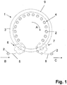
- 1 is a filling machine of rotating design for the aseptic free-jet filling of containers 2 in the form of bottles with a liquid product.
- the filling machine 1 has, as such a circumferential design, a rotor 3 which can be driven in rotation around a vertical machine axis MA, is distributed around its circumference at uniform angular intervals about the machine axis MA and into which the same radial distance from the machine axis MA a plurality of filling positions 4 are formed.
- the packaging to be filled in the form of containers 2 are supplied via an outer conveyor 5 (arrow B) and transferred to a container inlet 6 each to a filling position 4.
- the filled containers 2 are removed at a container outlet 7 the filling positions 4 and fed via an outer conveyor 8 for further treatment (arrow C).
- arrow C At least on the angular range of the rotational movement of the rotor 3 between the container inlet 6 and the container outlet 7, the filling positions 4 and the container 2 provided on these move in an insulator or in an enclosure 9, whose volume is kept as small as possible.
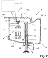
- FIG. 2 shows one of the filling positions 4 as well as the housing 9 in more detail in an embodiment of the filling machine 1.
- Each filling position 4 includes, inter alia, a filling element 10, which is arranged on the circumference of the rotor 3 and the circumference of a rotor element 3.1, above this rotor element 3.1 such that only a filler neck 11 of the filling element 10 projects beyond the underside of the rotor element 3.1.
- the rotor element 3.1 is formed in the form of a circular disc in the illustrated embodiment and lies with its top and bottom in each case in a plane which is cut perpendicularly from the machine axis MA.
- the filling element 10 is formed in the usual manner known to those skilled in the art, namely. with a liquid channel, not shown, which is connected to an upper end with a common for all filling elements 10 of the filling machine 1, provided on the rotor 3 and during filling with the filling material at least partially filled Golfgutkessel 12 and at the lower end of the Gregutstutzens 11 in a discharge opening 13th (Füllgutauslass) opens, from which flows the liquid medium during filling the respective container 2 through its container opening in the free jet.
- a liquid valve is provided with which the amount of product introduced into the container 2 is controlled.
- Each filling position 4 also has below the filler neck 11 to a container carrier 14, which in the illustrated embodiment at a the Machine axis MA concentrically enclosing circular cylindrical rotor element 3.2 is fixed and stands away from the relative to the machine axis MA radially outer side of this rotor element 3.2 radially to the machine axis.
- a container carrier 14 of the container to be filled 2 is held with a formed below the container mouth flange hanging, in such a way that the axis of the container 2 is arranged coaxially or substantially coaxially with a parallel to the machine axis MA oriented Greenelementachse FA and the container mouth in the direction of the Greelementachse FA is spaced from the lower end of the filler neck 11.
- the container carrier 14 and held on this container 2 are housed in an insulator interior 15 of the housing 9 , which is acted upon (insulator interior) with a sterile gas and / or vapor medium, for example with sterile air, in such a way that in the insulator interior 15, a flow of the sterile vapor and / or gaseous medium, inter alia, in such a way that this medium exits the container inlet 6 and the container outlet 7, where the enclosure 9 is open or ends.
- a sterile gas and / or vapor medium for example with sterile air
- the enclosure 9 delimiting the insulator space 15 is formed by a housing part which is provided on the rotor 3 and encircling it and which consists essentially of the two rotor elements 3.1 and 3.2, and a housing part 16 which does not encircle the rotor Machine frame of the filling machine 1 is provided and which labyrinth seal overlapping connected to the relation to the machine axis MA radially outer region of the rotor element 3.1 or to the lower end of the rotor element 3.2.
- the Einhausungselement consists essentially of a relative to the machine axis MA radially outer and the machine axis MA annularly enclosing housing element 16.1 with an upper, radially inwardly guided and the transition to the rotor element 3.1 forming annular portion 16.1.1 and from a to the lower end of the housing element 16 subsequent housing element 16.2.
- the latter forms the bottom of the insulator space 15, with an inclined bottom surface for discharging liquid ingredients.
- the bottom surface is inclined in this embodiment so that it falls radially outwardly with respect to the machine axis MA.
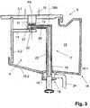
- each flushing cap 17 includes, inter alia, a hollow shaft 18, which is arranged with a part of its length in the insulator space 5, sealed at its lower end led out of the insulator space through the housing element 16.2 and there rotatable or pivotable about its parallel to the machine axis with a rotary coupling 19 MA arranged shaft axis WA is stored.
- a radially projecting arm 20 which forms a Spülkappenelement 21 with a Spülkappenö réelle 22 at its free end.
- the latter is connected via a discharge channel 23, which is partially formed in the arm 20 and partially in the shaft 18, with a fluid space 19.1 of the rotary joint 19 and via this fluid space 19.1 with a return line 24. It is understood that the channel 23 is open only at the Spülkappenö réelle 22 and at its exit into the liquid space 19.1.
- the shafts 18 are arranged such that the axes WA are offset radially outward relative to the filler element axes FA relative to the machine axis MA.
- the Spülkappen 17 are provided with its axis WA at the same angular intervals or in the same pitch around the machine axis MA distributed as the filling elements 10, so that with the exception of the container inlet 6 and the container outlet 7 each filling element 10, a flushing cap 17 is assigned.
- the rinsing caps 17 are missing in order to allow a radial feeding and removal of the container 2 there.
- This feeding for the tight connection of the Spülkappen 17 to the filling elements 10 is carried out by lifting the Spülkappen 17 and / or by lowering the rotor 3 in the direction of the machine axis MA.
- the return channel 24 can be provided jointly for all rinsing caps 17 or in each case for a group of several rinsing caps 17, specifically when the fluid space 19.1 is designed as a ring channel common to all rinsing caps 17 or a group of such rinsing caps.
- Both the drive for pivoting the Spülkappen 17 and the drive for delivering the Spülkappen 17 to the filler neck 11 and the removal of the Spülkappen 17 of the filler neck 11 are located outside of the enclosure 9 and the insulator space 15th
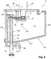
- FIG. 4 shows in a representation similar FIG. 3 an embodiment that differs from the embodiment of the Figures 2 and 3 only differs in that the shafts 18 are arranged with their axes WA relative to the machine axis MA radially within the movement path on which the filling elements 10 rotate with their Greesen FA during the filling operation.
- the container carriers 14a corresponding to the container carriers 14 are corresponding to FIG FIG. 5 designed elbow-like.
- the container carrier 14a are formed such that their attachment to the rotor element 3.1 and its cooperating with the containers 2 for holding portion offset relative to the rotational direction A of the rotor 3 by an angular amount against each other, thereby pivoting the arms 20 with their Spülkappenimplantationn 21 under the filler neck 11 is made possible.
- each angle-like container carrier 14 is held at the free end of a leg via a bolt 25 on the rotor element 3.1.
- FIG. 6 shows an embodiment of the filling positions 4, which differs from the filling positions of FIGS. 2 to 5 differs in that the container support 14b are pivotally mounted about a container support axis BA parallel to the machine axis MA on a shaft 26, namely pivotally between a working position in which the respective container support 14b is below the filler neck 11, and a non-use position in which the container carrier 14b laterally from the filler neck 11, that is offset relative to this relative to the machine axis MA radially inwardly.
- flushing caps 17b are provided whose shafts 18 are arranged with their axis at the same radial distance from the machine axis MA as the filling element axes FA, so that during cleaning and / or sterilization, in particular also during the CIP process. Cleaning and / or sterilization Each filling element 10 with its filling element axis FA is arranged coaxially with the axis of a flushing cap 17b or its shaft 18. At the upper end of each shaft 18 is performed directly with the Spülkappenö réelle 22 forming Spülkappenelement 21. The shafts 18 are axially displaceable (double arrow D) and sealed by the housing element 16.2 performed.
- the lower end of the channel 23 of each shaft 18 opens into a fluid channel 27, to which in turn the return line 24, for example in the form of a flexible conduit for discharging the cleaning and / or sterilization medium is connected.
- the fluid channel 27 is preferably a common annular channel common to all the flushing caps 17b on a circumferential support ring 28 concentrically surrounding the machine axis MA and cooperating with a lifting device 29 for lifting and lowering all the flushing caps 17b.
- the lifting device 29 is formed for example by at least one lifting cylinder.
- the cleaning and / or disinfecting the filling elements 10 takes place in this embodiment in the form that with stopped rotor 3 and with their Greelementachsen FA co-axial with the axes of the Spülbappen 17b arranged filling elements 10, the container carrier 14b pivoted into its non-use position and then with the lifting device 29 all scavenging caps 17b as far retracted or raised in the insulator space 15 that they sealed with their Spülkappenettin 21, ie in sealing position against a filler neck 11 abut.
- the cleaning and / or sterilizing medium flowing through the filling elements 10 is in turn discharged via the channels 23 and the fluid channel 27 and the return 24.
- the flushing caps 17b are moved back to their lower starting position with a large stroke, so that they are below the movement path with their flushing cap element 21, on which the containers 2 suspended from the container supports 14b rotate during filling operation. Before receiving the filling operation, of course, the container carrier 17b are in turn pivoted back into their working position.
- FIG. 7 shows an embodiment in which the Spülkappen 17c on the housing element 16.1 for delivery to the filler neck 11 of the filling elements 10 and for removing these filler neck 11 relative to the machine axis MA radially displaceable (double arrow E) are. It can also be of particular advantage if the rinsing caps 17c can additionally be lifted and lowered in the direction of the filling element axis FA (double arrow F).
- All embodiments also have in common that when using an enclosure 9 enclosing an insulator space 9, all actuators or their elements for advancing and removing the flushing caps 17, 17a-17c are arranged on the filling elements 10 or of the filling elements 10 outside of the insulator space 15 are.
- All embodiments also have in common that for the removal of the cleaning and / or sterilization medium, in particular also in the CIP cleaning and / or sterilization no aseptic or structurally complicated rotary connection between the rotor 3 and the machine frame of the filling machine 1 not rotating with the rotor is required, but the discharge of the cleaning and / or sterilization medium in the manner described above over the not provided on the rotor 3 flushing caps 17, 17a - 17c takes place.
- the invention has been described above exclusively by way of example for neck handling containers, that is to say containers which are held at least during a section of the production process on a neck ring mounted below the mouth. It goes without saying that the present invention can also be applied to those containers which do not have a neck ring and thus stand up on their container bottom during the production process.
- the measure necessary for this purpose namely to form the container carrier not as a receiving element for the neck ring of a container, but as a stand plate for receiving the container bottom has long been known to the skilled person since in the art container filling machines are known both in Halsring- and in floor design , The measures required for this modification are familiar to him, so that at this point can be dispensed with a detailed representation of a corresponding embodiment.
- the term container carrier is understood to mean either a neck ring receptacle or else a container pedestal.
Landscapes
- Filling Of Jars Or Cans And Processes For Cleaning And Sealing Jars (AREA)
Description
Die Erfindung bezieht sich auf eine Füllmaschine gemäß dem Oberbegriff des Patentanspruchs 1, und wie aus der
Füllmaschinen zum Füllen von Packmitteln, insbesondere Flaschen oder dergleichen Behältern, mit einem flüssigen Füllgut sind in zahlreichen Ausführungen bekannt. Bekannt ist es hierbei insbesondere auch, an dem umlaufenden Transportelement bzw. Rotor der Füllmaschine Spülkappen mit einem Rücklaufkanal für das beim Spülen, Reinigen und/oder Desinfizieren verwendeten Mediums vorzusehen (
Bekannt sind weiterhin auch Füllmaschinen umlaufender Bauart für ein antiseptisches Füllen von Packmitteln, z.B. Flaschen oder anderen Behältern mit einem flüssigen Füllgut, speziell auch für ein Freistrahlfüllen. Um eine Kontamination des Füllgutes während des Füllens zu vermeiden, weisen derartige Füllmaschinen eine einen Isolatorraum bildende Einhausung (Isolator) auf, in der sich die Füllpositionen und die zu füllenden Packmittel zumindest während des Füllprozesses bewegen. Derartige Füllmaschinen erfordern aber auch, dass unabhängig von der Reinigung und/oder Sterilisation der hierfür mit den Spülkappen verschlossenen Füllelemente auch eine Behandlung des Isolatorraumes und sämtlicher Flächen innerhalb dieses Raumes mit einem Reinigungs- und/oder Sterilisationsmedium erfolgt, beispielsweise mit einem heißen, dampfförmigen Medium, z.B. mit Wasserdampf. Hierbei muss insbesondere vermieden werden, dass sich flüssiges Reinigungsmedium oder Kondensat dieses Mediums in Bereichen innerhalb des Isolatorraumes sammelt, beispielsweise durch eine mangelnde Ableitung. Problematisch ist hierbei u.a., dass vielfach die Antriebe für das Bewegen der Spülkappen zwischen ihrer Ausgangsposition und Arbeitsposition ebenfalls innerhalb des Isolatorraumes angeordnet sind und zusätzliche Flächen und verwinkelte Bereiche bilden, an denen sich Reinigungs- oder Sterilisationsmedium oder Kondensat ablagern kann.Also known are filling machines of peripheral design for an antiseptic filling of packaging materials, such as bottles or other containers with a liquid product, especially for free jet filling. In order to avoid contamination of the filling material during filling, such filling machines have an insulator-forming housing (insulator) in which the filling positions and the packaging material to be filled at least move during the filling process. But such filling machines also require that regardless of the cleaning and / or sterilization of this closed with the rinsing caps filling elements and a treatment of the insulator space and all surfaces within this space with a cleaning and / or sterilization medium takes place, for example with a hot, vaporous medium, for example with water vapor. In this case, it must be avoided in particular that liquid cleaning medium or condensate of this medium collects in areas within the insulator space, for example by a lack of discharge. The problem here is, inter alia, that in many cases the drives for moving the Spülkappen between their starting position and working position are also located within the insulator space and form additional areas and angled areas where cleaning or sterilization medium or condensate can be deposited.
Aufgabe der Erfindung ist es, eine Füllmaschine aufzuzeigen, die die vorgenannten Nachteile vermeidet und bei hoher Betriebssicherheit eine vereinfachte konstruktive Ausgestaltung ermöglicht. Zur Lösung dieser Aufgabe ist eine Füllmaschine entsprechend dem Patentanspruch 1 ausgebildet.The object of the invention is to show a filling machine which avoids the aforementioned disadvantages and allows high operational reliability a simplified structural design. To solve this problem, a filling machine according to
"Packmittel" sind im Sinne der Erfindung insbesondere Behälter, wie Dosen, Flaschen, Tuben, Pourches, jeweils aus Metall, Glas und/oder Kunststoff, aber auch andere Packmittel, die zum Abfüllen von flüssigen oder viskosen Produkten geeignet sind."Packaging" are in the context of the invention, in particular containers, such as cans, bottles, tubes, Pourches, each made of metal, glass and / or plastic, but also other packaging, which are suitable for filling liquid or viscous products.
Unter "Freistrahlfüllen" ist im Sinne der Erfindung ein Verfahren zu verstehen, bei dem das flüssige Füllgut dem zu befüllenden Packmittel oder Behälter in einem freien Füllstrahl zufließt, wobei das Packmittel mit seiner Packmittelmündung oder - öffnung nicht am Füllelement anliegt, sondern von dem Füllelement bzw. von einem dortigen Füllgutauslass beabstandet ist."Free jet filling" in the sense of the invention is to be understood as meaning a process in which the liquid filling material flows into the filling material or container to be filled in a free filling jet, the packaging means with its packaging agent opening or opening not resting on the filling element, but instead of the filling element or filler . Is spaced from a local Füllgutauslass.
Der Ausdruck "im Wesentlichen" bzw. "etwa" bedeutet im Sinne der Erfindung Abweichungen vom jeweils exakten Wert um +/- 10%, bevorzugt um +/- 5% und/oder Abweichungen in Form von für die Funktion unbedeutenden Änderungen. Weiterbildungen, Vorteile und Anwendungsmöglichkeiten der Erfindung ergeben sich auch aus der nachfolgenden Beschreibung von Ausführungsbeispielen und aus den Figuren.The expression "essentially" or "approximately" in the sense of the invention means deviations from the exact value by +/- 10%, preferably by +/- 5% and / or deviations in the form of changes that are insignificant for the function. Further developments, advantages and applications of the invention will become apparent from the following description of exemplary embodiments and from the figures.
Die Erfindung wird im Folgenden anhand der Figuren an Ausführungsbeispielen näher erläutert. Es zeigen:
-
Fig. 1 in schematischer Darstellung und in Draufsicht eine Füllmaschine umlaufender Bauart zum aseptischen Freistrahlfüllen von Behältern in Form von Flaschen mit einem flüssigen Füllgut; -
Fig. 2 in schematischer Teildarstellung und im Schnitt eine der Füllpositionen der Füllmaschine derFigur 1 -
Fig. 3 die Füllposition derFigur 2 -
Fig. 4 eine Darstellung wieFigur 3 -
Fig. 5 einen Schnitt entsprechend der Linie I - I derFigur 4 -
Fig. 6 und7 Darstellungen ähnlich denFiguren 3
-
Fig. 1 in a schematic representation and in plan view of a filling machine of rotating design for aseptic free jet filling of containers in the form of bottles with a liquid filling material; -
Fig. 2 in a schematic partial view and in section one of the filling positions of the filling machine ofFIG. 1 , together with an enclosure (insulator) receiving the containers during filling during the filling process, in one embodiment of the filling machine according to the invention; -
Fig. 3 the filling position ofFIG. 2 during cleaning with a liquid and / or gas and / or vapor treatment medium, for example during CIP cleaning and / or sterilization; -
Fig. 4 a representation likeFIG. 3 in a further embodiment of the filling machine according to the invention; -
Fig. 5 a section corresponding to the line I - I ofFIG. 4 ; -
Fig. 6 and7 Representations similar to theFigures 3 and 4 in further embodiments of the invention.
In den Figuren ist 1 eine Füllmaschine umlaufender Bauart zum aseptischen Freistrahlfüllen von Behältern 2 in Form von Flaschen mit einem flüssigen Füllgut. Die Füllmaschine 1 weist als solche umlaufender Bauart einen um eine vertikale Maschinenachse MA umlaufend antreibbaren Rotor 3 auf, an dessen Umfang in gleichmäßigen Winkelabständen um die Maschinenachse MA verteilt und in den selben radialen Abstand von der Maschinenachse MA eine Vielzahl von Füllpositionen 4 gebildet sind. Die zu füllenden Packmittel in Form von Behältern 2 werden über einen äußeren Transporteur 5 zugeführt (Pfeil B) und an einem Behältereinlauf 6 jeweils an eine Füllposition 4 übergeben. Die gefüllten Behälter 2 werden an einem Behälterauslauf 7 den Füllpositionen 4 entnommen und über einen äußeren Transporteur 8 einer weiteren Behandlung zugeführt (Pfeil C). Zumindest auf dem Winkelbereich der Drehbewegung des Rotors 3 zwischen dem Behältereinlauf 6 und dem Behälterauslauf 7 bewegen sich die Füllpositionen 4 und die an diesen vorgesehenen Behälter 2 in einem Isolator oder in einer Einhausung 9, deren Volumen möglichst klein gehalten ist.In the figures, 1 is a filling machine of rotating design for the aseptic free-jet filling of
Die
Das Füllelement 10 ist in der üblichen, dem Fachmann bekannten Weise ausgebildet, und zwar u.a. mit einem nicht dargestellten Flüssigkeitskanal, der mit einem oberen Ende mit einem für sämtliche Füllelemente 10 der Füllmaschine 1 gemeinsamen, am Rotor 3 vorgesehenen und während des Füllbetriebes mit dem Füllgut zumindest teilgefüllten Füllgutkessel 12 verbunden ist und am unteren Ende des Füllgutstutzens 11 in einer Abgabeöffnung 13 (Füllgutauslass) mündet, aus der das flüssige Füllgut während des Füllens dem jeweiligen Behälter 2 durch seine Behälteröffnung im freien Strahl zufließt. Im Inneren des Flüssigkeitskanals ist ein Flüssigkeitsventil vorgesehen, mit welchem die in die Behälter 2 eingebrachte Füllgutmenge gesteuert wird.The filling
Jede Füllposition 4 weist weiterhin unterhalb des Füllstutzens 11 einen Behälterträger 14 auf, der bei der dargestellten Ausführungsform an einem die Maschinenachse MA konzentrisch umschließenden kreiszylinderförmigen Rotorelement 3.2 befestigt ist und von der bezogen auf die Maschinenachse MA radial außenliegenden Seite dieses Rotorelementes 3.2 radial zur Maschinenachse wegsteht. An dem jeweiligen Behälterträger 14 ist der zu füllende Behälter 2 mit einem unterhalb der Behältermündung ausgebildeten Flansch hängend gehalten, und zwar derart, dass die Achse des Behälters 2 achsgleich oder im Wesentlichen achsgleich mit einer parallel zur Maschinenachse MA orientierten Füllelementachse FA angeordnet ist und die Behältermündung in Richtung der Füllelementachse FA von dem unteren Ende des Füllstutzens 11 beabstandet ist. Zumindest während des Füllprozesses, der auf dem Winkelbereich der Drehbewegung des Rotors 3 zwischen dem Behältereinlauf 6 und dem Behälterauslauf 7 erfolgt, sind das untere Ende des Füllstutzens 11, der Behälterträger 14 und der an diesem gehaltene Behälter 2 in einem Isolatorinnenraum 15 der Einhausung 9 aufgenommen, der (Isolatorinnenraum) mit einem sterilen gas- und/oder dampfförmigen Medium, beispielsweise mit steriler Luft beaufschlagt ist, und zwar derart, dass sich in dem Isolatorinnenraum 15 eine Strömung des sterilen dampf- und/oder gasförmigen Mediums u.a. in der Weise einstellt, dass dieses Medium am Behältereinlauf 6 und am Behälterauslauf 7 austritt, wo die Einhausung 9 offen ist oder endet.Each
Bei der dargestellten Ausführungsform ist die den Isolatorraum 15 begrenzende Einhausung 9 von einem am Rotor 3 vorgesehenen und mit diesem umlaufenden Einhausungsteil, der im Wesentlichen aus den beiden Rotorelementen 3.1 und 3.2 besteht, und einem mit dem Rotor nicht umlaufenden Einhausungsteil 16 gebildet, welcher an dem Maschinengestell der Füllmaschine 1 vorgesehen ist und welches labyrinthdichtungsartig überlappend an den bezogen auf die Maschinenachse MA radial außen liegenden Bereich des Rotorelementes 3.1 bzw. an das untere Ende des Rotorelementes 3.2 anschließt. Bei der dargestellten Ausführungsform besteht das Einhausungselement im Wesentlichen aus einem bezogen auf die Maschinenachse MA radial außen liegenden und die Maschinenachse MA ringförmig umschließenden Einhausungselement 16.1 mit einem oberen, radial nach innen geführten und den Übergang zum Rotorelement 3.1 bildenden ringförmigen Abschnitt 16.1.1 und aus einem an das untere Ende des Einhausungselementes 16 anschließenden Einhausungselement 16.2. Letzteres bildet den Boden des Isolatorraumes 15, und zwar mit einer geneigten Bodenfläche zum Ableiten von flüssigen Bestandteilen. Die Bodenfläche ist bei dieser Ausführungsform derart geneigt, dass sie bezogen auf die Maschinenachse MA radial nach außen hin abfällt.In the illustrated embodiment, the
Eine Besonderheit der Füllmaschine 1 besteht darin, dass den einzelnen Füllelementen 10 solche Spülkappen 17 zugeordnet sind, die nicht mit dem Rotor 3 umlaufen. Bei der in den
Bei der in den
Durch einen auf das untere, aus dem Isolatorraum 15 herausgeführten Ende der jeweiligen Welle 18 einwirkenden Antrieb ist diese um ihre Achse WA um einen Winkelbetrag von 90° oder etwa 90° zwischen einer Ausgangsposition, in der für den Füllbetrieb die Arme 20 und die Spülkappenelemente 21 außerhalb der Bewegungsbahn der umlaufenden Füllelemente 10, Behälterträger 14 und Behälter 2 angeordnet sind, und einer Arbeitsposition schwenkbar, in der sich die Arme 20 mit ihren Spülkappenelementen 21 jeweils unterhalb eines Füllstutzens 11 befinden. Durch ein Zustellbewegung in der Füllelementachse FA kann die betreffende Spülkappe in Dichtlage am Füllstutzen 10 gebracht werden, so dass die Spülkappenöffnung 22 dicht an die Abgabeöffnung 13 des betreffenden Füllelementes 10 anschließt, beispielsweise unter Mitwirkung einer Dichtung. Dieses Zustellen für das dichte Anschließen der Spülkappen 17 an die Füllelemente 10 erfolgt durch Anheben der Spülkappen 17 und/oder durch Absenken des Rotors 3 in Richtung der Maschinenachse MA. Das bei der CIP-Reinigung und/oder -Sterilisation den Flüssigkeitskanal oder andere Kanäle der Füllelemente 10 durchströmende Reinigungs- und/oder Sterilisationsmedium, auch anderes dampf- und/oder gasförmiges Reinigungs- und/oder Sterilisationsmedium sowie evtl. anfallendes Kondensat wird über die Kanäle 23 der Spülkappen 17 in den Rücklaufkanal 24 abgeleitet. Der Rücklaufkanal 24 kann für sämtliche Spülkappen 17 oder aber jeweils für eine Gruppe mehrerer Spülkappen 17 gemeinsam vorgesehen sein, und zwar dann, wenn der Fluidraum 19.1 als ein für sämtliche Spülkappen 17 oder eine Gruppe solcher Spülkappen gemeinsamer Ringkanal ausgebildet ist.By acting on the lower, led out of the
Sowohl der Antrieb für das Schwenken der Spülkappen 17 als auch der Antrieb für das Zustellen der Spülkappen 17 an die Füllstutzen 11 und das Entfernen der Spülkappen 17 von den Füllstutzen 11 befinden sich außerhalb der Einhausung 9 bzw. des Isolatorraumes 15.Both the drive for pivoting the
Um bei der CIP-Reinigung und/oder-Sterilisation sowie bei der Behandlung mit einem anderen dampf- und/oder gasförmigen Medium sämtliche Füllelemente 10 zu erfassen, ist es bei der in den
Die
Mehr im Detail sind die Behälterträger 14a derart ausgebildet, dass deren Befestigung am Rotorelement 3.1 und deren mit den Behältern 2 zum Halten zusammenwirkende Abschnitt bezogen auf die Drehrichtung A des Rotors 3 um einem Winkelbetrag gegeneinander versetzt sind, sodass dadurch ein Schwenken der Arme 20 mit ihren Spülkappenelementen 21 unter die Füllstutzen 11 ermöglicht ist. Im Detail ist jeder winkelartige Behälterträger 14 am freien Ende eines Schenkels über einen Bolzen 25 an dem Rotorelement 3.1 gehalten.More in detail, the
Insgesamt werden ein entsprechender Behälterträger 14a und eine entsprechende Spülkappe 17a in der
Die
Das Reinigen und/oder Desinfizieren der Füllelemente 10 erfolgt bei dieser Ausführungsform in der Form, dass bei angehaltenem Rotor 3 und bei mit ihren Füllelementachsen FA achsgleich mit den Achsen der Spülkappen 17b angeordneten Füllelementen 10 die Behälterträger 14b in ihre Nichtgebrauchsposition geschwenkt und anschließend mit der Hubeinrichtung 29 sämtliche Spülkappen 17b soweit in den Isolatorraum 15 eingefahren bzw. angehoben werden, dass sie mit ihren Spülkappenelementen 21 abgedichtet, d.h. in Dichtlage gegen einen Füllstutzen 11 anliegen. Das die Füllelemente 10 durchströmende Reinigungs- und/oder Sterilisationsmedium wird wiederum über die Kanäle 23 und den Fluid-Kanal 27 sowie den Rücklauf 24 abgeleitet. Nach dem Reinigen und/oder Sterilisieren werden die Spülkappen 17b mit großem Hub in ihre untere Ausgangsstellung zurückbewegt, sodass sie sich mit ihren Spülkappenelement 21 unterhalb der Bewegungsbahn befinden, auf der beim Füllbetrieb die an den Behälterträgern 14b hängend gehaltenen Behälter 2 umlaufen. Vor Aufnahme des Füllbetriebes werden selbstverständlich die Behälterträger 17b wiederum in ihre Arbeitsposition zurückgeschwenkt.The cleaning and / or disinfecting the filling
Die
Die Erfindung wurde voranstehend an verschiedenen Ausführungsbeispielen beschrieben. Es versteht sich, dass zahlreiche Änderungen sowie Abwandlungen möglich sind, ohne den durch die nachfolgenden Ansprüche definierten Umfang zu verlassen. So besteht z.B. die Möglichkeit, für die Spülkappen jeweils einen Verschluss vorzusehen, der während des Füllbetriebes die Spülkappenöffnung 22 verschließt. In der
Allen Ausführungen ist gemeinsam, dass die Spülkappen 17, 17a - 17c nicht an dem umlaufenden Rotor 3 oder an Elementen dieses Rotors vorgesehen sind, sondern an einem mit dem Rotor nicht umlaufenden Element der Füllmaschine, nämlich bei den dargestellten Ausführungsform an dem Einhausungsteil 16.All embodiments have in common that the
Allen Ausführungsformen ist weiterhin auch gemeinsam, dass bei Verwendung einer einen Isolatorraum 15 umschließenden Einhausung 9 sämtliche Stellantriebe oder deren Elemente zum Zustellen und Entfernen der Spülkappen 17, 17a - 17c an die Füllelemente 10 bzw. von den Füllelementen 10 außerhalb des (Isolatorraumes 15) angeordnet sind. Dies bietet u.a. den zusätzlichen Vorteil, dass bei der auch notwendigen Reinigung des Isolatorraumes die Anzahl der dortigen, zu reinigen und/oder zu sterilisierenden Elemente stark reduziert ist und insbesondere auch problemlos Bereiche vermieden werden können, an denen sich beispielsweise bei einer Reinigung und/oder Sterilisation des Isolatorraumes 15 in einer unerwünschten und die Reinigungs- und/oder Sterilisationsqualität beeinträchtigenden Weise Reinigungs- und/oder Sterilisationsmedium und/oder aus dem Reinigungs- und/oder Sterilisationsmedium abscheidendes Kondensat sammeln könnte.All embodiments also have in common that when using an
Allen Ausführungsformen ist weiterhin auch gemeinsam, dass für das Abführen des Reinigungs- und/oder Sterilisationsmedium insbesondere auch bei der CIPReinigung und/oder -Sterilisation keine aseptische bzw. konstruktiv aufwendige Drehverbindung zwischen dem Rotor 3 und dem mit dem Rotor nicht umlaufenden Maschinengestell der Füllmaschine 1 erforderlich ist, sondern das Abführen des Reinigungs- und/oder Sterilisationsmediums in der oben beschriebenen Weise vereinfacht über die nicht am Rotor 3 vorgesehenen Spülkappen 17, 17a - 17c erfolgt.All embodiments also have in common that for the removal of the cleaning and / or sterilization medium, in particular also in the CIP cleaning and / or sterilization no aseptic or structurally complicated rotary connection between the
Die Erfindung wurde voranstehend ausschließlich an einem Beispiel für Freistrahlfüllung erläutert. Es versteht sich von selbst, dass die vorliegende Erfindung auch für alle Füllverfahren mit Gegendruck angewendet werden kann. Die dazu notwendige Verwendung eines entsprechenden Füllventils ist für den Fachmann selbstverständlich, die dazu notwendigen Maßnahmen sind ihm geläufig, so dass an dieser Stelle auf eine ausführliche Darstellung eines entsprechenden Ausführungsbeispiels verzichtet werden kann.The invention has been explained above exclusively with an example of free-jet filling. It goes without saying that the present invention can also be applied to all counterpressure filling methods. The necessary use of a corresponding filling valve is obvious to the person skilled in the art, the necessary measures are familiar to him, so that it is possible to dispense with a detailed representation of a corresponding exemplary embodiment at this point.
Weiterhin wurde die Erfindung voranstehend ausschließlich an einem Beispiel für Neckhandling-Behälter, also solche Behälter, die zumindest während eines Abschnittes des Produktionsprozesses an einem, unterhalb der Mündung angebrachten Halsring gehalten sind, erläutert. Es versteht sich von selbst, dass die vorliegende Erfindung auch für solche Behälter angewendet werden kann, die keinen Halsring aufweisen, und somit während des Produktionsprozesses auf ihrem Behälterboden aufstehen. Die dazu notwendige Maßnahme, nämlich den Behälterträger nicht als Aufnahmeelement für den Halsring eines Behälters, sondern als Standteller für die Aufnahme des Behälterbodens auszubilden ist dem Fachmann seit langer Zeit bekannt, da im Stand der Technik Behälterfüllmaschinen sowohl in Halsring- als auch in Standbodenausführung bekannt sind. Die für diese Abwandlung erforderlichen Maßnahmen sind ihm geläufig, so dass an dieser Stelle auf eine ausführliche Darstellung eines entsprechenden Ausführungsbeispiels verzichtet werden kann. Im Rahmen der vorliegenden Erfindung ist also je nach Anwendungsfall unter dem Begriff Behälterträger entweder eine Halsringaufnahme oder aber ein Behälterstandteller zu verstehen.Furthermore, the invention has been described above exclusively by way of example for neck handling containers, that is to say containers which are held at least during a section of the production process on a neck ring mounted below the mouth. It goes without saying that the present invention can also be applied to those containers which do not have a neck ring and thus stand up on their container bottom during the production process. The measure necessary for this purpose, namely to form the container carrier not as a receiving element for the neck ring of a container, but as a stand plate for receiving the container bottom has long been known to the skilled person since in the art container filling machines are known both in Halsring- and in floor design , The measures required for this modification are familiar to him, so that at this point can be dispensed with a detailed representation of a corresponding embodiment. In the context of the present invention, therefore, depending on the application, the term container carrier is understood to mean either a neck ring receptacle or else a container pedestal.
- 11
- Füllmaschinefilling Machine
- 22
- Behältercontainer
- 33
- Rotorrotor
- 3.1, 3.23.1, 3.2
- Rotorelementrotor member
- 44
- Füllpositionfilling position
- 55
- äußerer Transporteurexternal transporter
- 66
- Behältereinlaufcontainer inlet
- 77
- Behälterauslaufcontainer outlet
- 88th
- äußerer Transporteurexternal transporter
- 99
- Einhausung oder IsolatorEnclosure or insulator
- 1010
- Füllelementfiller
- 1111
- Füllstutzenfilling
- 1212
- FüllgutkesselFüllgutkessel
- 1313
- Abgabeöffnungdischarge opening
- 14, 14a, 14b14, 14a, 14b
- Behälterträgercontainer carrier
- 1515
- Isolatorraumisolator room
- 1616
- Einhausungsteilcasing part
- 16.1, 16.2, 16.316.1, 16.2, 16.3
- Einhausungselementcase element
- 16.1.116.1.1
- Abschnittsection
- 17, 17a - 17c17, 17a - 17c
- Spülkappeflushing cap
- 1818
- Wellewave
- 1919
- Drehkupplungrotary joint
- 19.119.1
- Fluidkanalfluid channel
- 2020
- Armpoor
- 2121
- SpülkappenelementSpülkappenelement
- 2222
- SpülkappenöffnungSpülkappenöffnung
- 2323
- Kanalchannel
- 2424
- Rücklaufreturns
- 2525
- Bolzenbolt
- 2626
- Wellewave
- 2727
- Fluidkanalfluid channel
- 2828
- Trägercarrier
- 2929
- Hubeinrichtunglifting device
- 3030
- Verschlussshutter
- AA
- Drehrichtung des RotorsDirection of rotation of the rotor
- B, CB, C
-
Transportrichtung der Transporteure 5 und 8Transport direction of the
conveyors - DD
- Hub der Spülkappen 17bStroke of the flushing caps 17b
- E, FE, F
- Hub der Spülkappen 17cStroke of the flushing caps 17c
- FAFA
- Füllelementachsefilling element
- MAMA
- Maschinenachsemachine axis
- WAWA
-
Achse der Welle 18Axis of the
shaft 18
Claims (10)
- Filling machine, in particular for the aseptic filling of packaging means (2), for example, bottles or similar containers, with a fluid filling product, with a drivable transport element (3) circulating about at least one machine axis (MA) and with a plurality of filling positions (4) arranged at the transport element (3) with, in each case, at least one filling element (10) forming a discharge opening (13) for the filling product, and with a container carrier (14, 14a), as well as flushing caps (17, 17a-17c) arranged at the filling positions (4), which can be moved between a starting position, in which they are arranged outside the movement space of the filling elements (10) and the packaging means (2) located at these elements during the filling operation, and a working position, and specifically for forming a sealing position of the respective flushing cap (17, 17a-17c) against the filling element (10) in the working position, and for forming a flushing and/or cleaning path, enclosing at least one discharge opening (13) of the filling element (10), wherein the flushing caps (17, 17a-17c) are provided at a part (16) of the filling machine (1) which does not circulate with the transport element (3), characterised in that the filling machine (1) is configured with a housing (9), delimiting an isolator space (15), in which the filling elements (4) and the packaging means (2) are accommodated at least during the filling, wherein the flushing caps (17, 17a-17c) are provided at a housing part (16) which is not circulating with the transport element (3), wherein the drives for the movement and/or placement of the flushing caps (17, 17a-17c) are located between their starting position and working position outside the housing and the isolator space (15).
- Filling machine according to any one of the preceding claims [sic], characterized in that the flushing caps (17, 17a), for the movement between their starting position and the working position, can be pivoted about at least one pivot axis (WA), for example about a pivot axis (WA) oriented parallel to the at least one machine axis (MA), and/or by movement in an axis parallel to the machine axis (MA) or a filling element axis (FA) of the respective filling element (10).
- Filling machine according to claim 2, characterised in that the pivot axis (WA) of the flushing caps (17, 17a) is located outside or inside a motion path on which the filling elements (10) circulate with their filling element axes (FA).
- Filling machine according to any one of the preceding claims, characterised in that the flushing caps (17c) are capable of linear movement at least in one direction.
- Filling machine according to any one of the preceding claims, characterised in that the placement of the flushing caps (17, 17a-17c) into the sealing position at the filling elements (10) is effected by relative movement between the filling elements (10) and the flushing caps (17, 17a-17c) in an axial direction parallel or essentially parallel to the filling element axis (FA) or pivot axis (WA).
- Filling machine according to any one of the preceding claims, characterised in that the flushing caps (17, 17a-17c) are configured in each case with a return channel (23) for the cleaning and/or sterilisation medium.
- Filling machine according to any one of the preceding claims, characterised in that the housing (9) comprises the housing part (16) which does not circulate with the transport element, and a housing part (3.1, 3.2) which does circulate with the transport element (3), and that the transition between these housing parts is formed by the housing parts overlapping at that point.
- Filling machine according to any one of the preceding claims, characterised by closures (30) for closing the flushing caps (17a) in their starting position.
- Filling machine according to any one of the preceding claims, characterised in that it is configured for free-jet filling.
- Filling machine according to any one of the preceding claims, characterised in that it is configured for a filling under counter-pressure.
Priority Applications (1)
| Application Number | Priority Date | Filing Date | Title |
|---|---|---|---|
| SI201330148T SI2847123T1 (en) | 2012-05-10 | 2013-03-20 | Filling machine |
Applications Claiming Priority (2)
| Application Number | Priority Date | Filing Date | Title |
|---|---|---|---|
| DE102012009206A DE102012009206A1 (en) | 2012-05-10 | 2012-05-10 | filling Machine |
| PCT/EP2013/000836 WO2013167219A1 (en) | 2012-05-10 | 2013-03-20 | Filling machine |
Publications (2)
| Publication Number | Publication Date |
|---|---|
| EP2847123A1 EP2847123A1 (en) | 2015-03-18 |
| EP2847123B1 true EP2847123B1 (en) | 2016-02-17 |
Family
ID=48083094
Family Applications (1)
| Application Number | Title | Priority Date | Filing Date |
|---|---|---|---|
| EP13715130.4A Active EP2847123B1 (en) | 2012-05-10 | 2013-03-20 | Filling machine |
Country Status (5)
| Country | Link |
|---|---|
| US (1) | US20150090365A1 (en) |
| EP (1) | EP2847123B1 (en) |
| DE (1) | DE102012009206A1 (en) |
| SI (1) | SI2847123T1 (en) |
| WO (1) | WO2013167219A1 (en) |
Cited By (1)
| Publication number | Priority date | Publication date | Assignee | Title |
|---|---|---|---|---|
| IT202100008711A1 (en) * | 2021-04-07 | 2022-10-07 | Gea Procomac Spa | CONTAINER FILLING APPARATUS AND CONTAINER FILLING DEVICES SANITIZATION PROCEDURE |
Families Citing this family (4)
| Publication number | Priority date | Publication date | Assignee | Title |
|---|---|---|---|---|
| DE102012019161A1 (en) | 2012-09-28 | 2014-04-03 | Khs Gmbh | filling Machine |
| DE102014102960A1 (en) * | 2014-03-06 | 2015-09-10 | Krones Ag | Device for filling a container with a filling product |
| DE102015118619A1 (en) | 2015-10-30 | 2017-05-04 | Krones Ag | Apparatus for treating containers |
| CN110550592A (en) * | 2019-10-12 | 2019-12-10 | 广州达意隆包装机械股份有限公司 | False cup device and liquid filling machine |
Family Cites Families (17)
| Publication number | Priority date | Publication date | Assignee | Title |
|---|---|---|---|---|
| US4024896A (en) * | 1975-05-13 | 1977-05-24 | Shibuya Kogyo Company, Ltd. | Washing device for rotary filling machine |
| DE29713155U1 (en) * | 1997-07-24 | 1998-09-10 | Kronseder Maschf Krones | Rotary filler |
| JP4631146B2 (en) * | 2000-10-05 | 2011-02-16 | 四国化工機株式会社 | Cleaning device for filling nozzle |
| ES2233737T3 (en) * | 2002-04-22 | 2005-06-16 | Krones Ag | MACHINE FOR FILLING IN ASEPTIC CONDITIONS. |
| DE102004004331B3 (en) | 2004-01-29 | 2005-09-15 | Khs Maschinen- Und Anlagenbau Ag | Process for hot filling of a liquid filling material into bottles or the like container and filling machine for carrying out the method |
| DE102004011101B4 (en) * | 2004-03-06 | 2011-04-07 | Khs Gmbh | Filling elements and filling machine with such filling elements |
| WO2007019590A2 (en) * | 2005-08-08 | 2007-02-15 | Etienne Le Roux | Method and apparatus for automated cleaning of bottling equipment |
| US7686043B2 (en) * | 2005-12-14 | 2010-03-30 | Evergreen Packaging Inc. | Container filling apparatus including cleaning system |
| FR2899220B1 (en) * | 2006-03-31 | 2008-05-30 | Sidel Participations | CLEANING DEVICE FOR FILLING MACHINE |
| DE102006017706A1 (en) * | 2006-04-15 | 2007-10-25 | Khs Ag | Filling elements and filling machine with a filling element |
| DE102007024106B4 (en) * | 2007-05-22 | 2009-12-03 | Khs Ag | filling system |
| ES2342644B1 (en) * | 2008-03-17 | 2011-04-28 | Gallardo Ingenieria Del Embotellado, S.L. | CLEANING EQUIPMENT FOR A BOTTLE FILLING MACHINE. |
| DE102008029208A1 (en) * | 2008-06-19 | 2009-12-24 | Krones Ag | Freistrahlfüllsystem |
| DE102009033557A1 (en) * | 2009-07-16 | 2011-01-20 | Krones Ag | Device for bottling beverages with CIP cap control |
| DE102010006319A1 (en) * | 2010-01-29 | 2011-08-04 | Krones Ag, 93073 | Device for treating containers |
| DE102010013132A1 (en) * | 2010-03-26 | 2011-09-29 | Krones Ag | Apparatus for treating containers with height-adjustable isolator |
| DE102010031873A1 (en) * | 2010-07-21 | 2012-01-26 | Krones Aktiengesellschaft | Apparatus and method for filling containers with cleaning device |
-
2012
- 2012-05-10 DE DE102012009206A patent/DE102012009206A1/en not_active Ceased
-
2013
- 2013-03-20 SI SI201330148T patent/SI2847123T1/en unknown
- 2013-03-20 US US14/400,110 patent/US20150090365A1/en not_active Abandoned
- 2013-03-20 EP EP13715130.4A patent/EP2847123B1/en active Active
- 2013-03-20 WO PCT/EP2013/000836 patent/WO2013167219A1/en active Application Filing
Cited By (2)
| Publication number | Priority date | Publication date | Assignee | Title |
|---|---|---|---|---|
| IT202100008711A1 (en) * | 2021-04-07 | 2022-10-07 | Gea Procomac Spa | CONTAINER FILLING APPARATUS AND CONTAINER FILLING DEVICES SANITIZATION PROCEDURE |
| EP4071103A1 (en) * | 2021-04-07 | 2022-10-12 | Gea Procomac S.p.A. | Filling apparatus for containers and a process for sanitising filling devices for containers |
Also Published As
| Publication number | Publication date |
|---|---|
| WO2013167219A1 (en) | 2013-11-14 |
| SI2847123T1 (en) | 2016-04-29 |
| DE102012009206A1 (en) | 2013-11-14 |
| US20150090365A1 (en) | 2015-04-02 |
| EP2847123A1 (en) | 2015-03-18 |
Similar Documents
| Publication | Publication Date | Title |
|---|---|---|
| EP2035303B1 (en) | Method for handling containers and container handling machine | |
| EP2665676B1 (en) | Filling element comprising a spray nozzle or spray nozzle assembly, and method for cleaning machine elements | |
| EP2847123B1 (en) | Filling machine | |
| EP2043944A1 (en) | Treatment machine | |
| DE102008026632A1 (en) | sealing | |
| EP2999635A1 (en) | Container processing machine and method for operating a container processing machine | |
| EP2640660B1 (en) | Filling element and filling system or filling machine for free-jet filling of bottles or similar containers | |
| EP2900590B1 (en) | Filling machine | |
| EP2328829B1 (en) | Container handling machine, in particular capping machine | |
| EP2748102B1 (en) | Filling machine and method for controlling a filling machine | |
| EP1655264A2 (en) | Filling machine of the rotary type | |
| EP2928808B1 (en) | Filling machine | |
| EP2387543A2 (en) | Container-handling machine | |
| WO2017021043A1 (en) | Method for cleaning and/or disinfecting sealing elements, sealing machine, and sealing element | |
| DE102019135472A1 (en) | Filling machine | |
| WO2023046458A1 (en) | Closing device for closing containers | |
| WO2010060587A2 (en) | Device and method for treating bottles or similar containers | |
| EP2964562A1 (en) | Machine and method for filling containers and cleaning method |
Legal Events
| Date | Code | Title | Description |
|---|---|---|---|
| PUAI | Public reference made under article 153(3) epc to a published international application that has entered the european phase |
Free format text: ORIGINAL CODE: 0009012 |
|
| 17P | Request for examination filed |
Effective date: 20140829 |
|
| AK | Designated contracting states |
Kind code of ref document: A1 Designated state(s): AL AT BE BG CH CY CZ DE DK EE ES FI FR GB GR HR HU IE IS IT LI LT LU LV MC MK MT NL NO PL PT RO RS SE SI SK SM TR |
|
| AX | Request for extension of the european patent |
Extension state: BA ME |
|
| DAX | Request for extension of the european patent (deleted) | ||
| GRAP | Despatch of communication of intention to grant a patent |
Free format text: ORIGINAL CODE: EPIDOSNIGR1 |
|
| INTG | Intention to grant announced |
Effective date: 20150928 |
|
| GRAS | Grant fee paid |
Free format text: ORIGINAL CODE: EPIDOSNIGR3 |
|
| GRAA | (expected) grant |
Free format text: ORIGINAL CODE: 0009210 |
|
| AK | Designated contracting states |
Kind code of ref document: B1 Designated state(s): AL AT BE BG CH CY CZ DE DK EE ES FI FR GB GR HR HU IE IS IT LI LT LU LV MC MK MT NL NO PL PT RO RS SE SI SK SM TR |
|
| REG | Reference to a national code |
Ref country code: GB Ref legal event code: FG4D Free format text: NOT ENGLISH |
|
| REG | Reference to a national code |
Ref country code: CH Ref legal event code: EP |
|
| REG | Reference to a national code |
Ref country code: IE Ref legal event code: FG4D Free format text: LANGUAGE OF EP DOCUMENT: GERMAN |
|
| REG | Reference to a national code |
Ref country code: AT Ref legal event code: REF Ref document number: 775542 Country of ref document: AT Kind code of ref document: T Effective date: 20160315 |
|
| REG | Reference to a national code |
Ref country code: FR Ref legal event code: PLFP Year of fee payment: 4 |
|
| REG | Reference to a national code |
Ref country code: DE Ref legal event code: R096 Ref document number: 502013001958 Country of ref document: DE |
|
| REG | Reference to a national code |
Ref country code: NL Ref legal event code: MP Effective date: 20160217 |
|
| REG | Reference to a national code |
Ref country code: LT Ref legal event code: MG4D |
|
| PG25 | Lapsed in a contracting state [announced via postgrant information from national office to epo] |
Ref country code: GR Free format text: LAPSE BECAUSE OF FAILURE TO SUBMIT A TRANSLATION OF THE DESCRIPTION OR TO PAY THE FEE WITHIN THE PRESCRIBED TIME-LIMIT Effective date: 20160518 Ref country code: HR Free format text: LAPSE BECAUSE OF FAILURE TO SUBMIT A TRANSLATION OF THE DESCRIPTION OR TO PAY THE FEE WITHIN THE PRESCRIBED TIME-LIMIT Effective date: 20160217 Ref country code: NO Free format text: LAPSE BECAUSE OF FAILURE TO SUBMIT A TRANSLATION OF THE DESCRIPTION OR TO PAY THE FEE WITHIN THE PRESCRIBED TIME-LIMIT Effective date: 20160517 Ref country code: FI Free format text: LAPSE BECAUSE OF FAILURE TO SUBMIT A TRANSLATION OF THE DESCRIPTION OR TO PAY THE FEE WITHIN THE PRESCRIBED TIME-LIMIT Effective date: 20160217 Ref country code: ES Free format text: LAPSE BECAUSE OF FAILURE TO SUBMIT A TRANSLATION OF THE DESCRIPTION OR TO PAY THE FEE WITHIN THE PRESCRIBED TIME-LIMIT Effective date: 20160217 |
|
| PG25 | Lapsed in a contracting state [announced via postgrant information from national office to epo] |
Ref country code: SE Free format text: LAPSE BECAUSE OF FAILURE TO SUBMIT A TRANSLATION OF THE DESCRIPTION OR TO PAY THE FEE WITHIN THE PRESCRIBED TIME-LIMIT Effective date: 20160217 Ref country code: LV Free format text: LAPSE BECAUSE OF FAILURE TO SUBMIT A TRANSLATION OF THE DESCRIPTION OR TO PAY THE FEE WITHIN THE PRESCRIBED TIME-LIMIT Effective date: 20160217 Ref country code: PL Free format text: LAPSE BECAUSE OF FAILURE TO SUBMIT A TRANSLATION OF THE DESCRIPTION OR TO PAY THE FEE WITHIN THE PRESCRIBED TIME-LIMIT Effective date: 20160217 Ref country code: PT Free format text: LAPSE BECAUSE OF FAILURE TO SUBMIT A TRANSLATION OF THE DESCRIPTION OR TO PAY THE FEE WITHIN THE PRESCRIBED TIME-LIMIT Effective date: 20160617 Ref country code: RS Free format text: LAPSE BECAUSE OF FAILURE TO SUBMIT A TRANSLATION OF THE DESCRIPTION OR TO PAY THE FEE WITHIN THE PRESCRIBED TIME-LIMIT Effective date: 20160217 Ref country code: NL Free format text: LAPSE BECAUSE OF FAILURE TO SUBMIT A TRANSLATION OF THE DESCRIPTION OR TO PAY THE FEE WITHIN THE PRESCRIBED TIME-LIMIT Effective date: 20160217 Ref country code: LT Free format text: LAPSE BECAUSE OF FAILURE TO SUBMIT A TRANSLATION OF THE DESCRIPTION OR TO PAY THE FEE WITHIN THE PRESCRIBED TIME-LIMIT Effective date: 20160217 Ref country code: BE Free format text: LAPSE BECAUSE OF NON-PAYMENT OF DUE FEES Effective date: 20160331 |
|
| PG25 | Lapsed in a contracting state [announced via postgrant information from national office to epo] |
Ref country code: DK Free format text: LAPSE BECAUSE OF FAILURE TO SUBMIT A TRANSLATION OF THE DESCRIPTION OR TO PAY THE FEE WITHIN THE PRESCRIBED TIME-LIMIT Effective date: 20160217 Ref country code: EE Free format text: LAPSE BECAUSE OF FAILURE TO SUBMIT A TRANSLATION OF THE DESCRIPTION OR TO PAY THE FEE WITHIN THE PRESCRIBED TIME-LIMIT Effective date: 20160217 |
|
| REG | Reference to a national code |
Ref country code: CH Ref legal event code: PL |
|
| REG | Reference to a national code |
Ref country code: DE Ref legal event code: R097 Ref document number: 502013001958 Country of ref document: DE |
|
| PG25 | Lapsed in a contracting state [announced via postgrant information from national office to epo] |
Ref country code: CZ Free format text: LAPSE BECAUSE OF FAILURE TO SUBMIT A TRANSLATION OF THE DESCRIPTION OR TO PAY THE FEE WITHIN THE PRESCRIBED TIME-LIMIT Effective date: 20160217 Ref country code: SK Free format text: LAPSE BECAUSE OF FAILURE TO SUBMIT A TRANSLATION OF THE DESCRIPTION OR TO PAY THE FEE WITHIN THE PRESCRIBED TIME-LIMIT Effective date: 20160217 Ref country code: RO Free format text: LAPSE BECAUSE OF FAILURE TO SUBMIT A TRANSLATION OF THE DESCRIPTION OR TO PAY THE FEE WITHIN THE PRESCRIBED TIME-LIMIT Effective date: 20160217 Ref country code: SM Free format text: LAPSE BECAUSE OF FAILURE TO SUBMIT A TRANSLATION OF THE DESCRIPTION OR TO PAY THE FEE WITHIN THE PRESCRIBED TIME-LIMIT Effective date: 20160217 |
|
| PLBE | No opposition filed within time limit |
Free format text: ORIGINAL CODE: 0009261 |
|
| STAA | Information on the status of an ep patent application or granted ep patent |
Free format text: STATUS: NO OPPOSITION FILED WITHIN TIME LIMIT |
|
| REG | Reference to a national code |
Ref country code: IE Ref legal event code: MM4A |
|
| 26N | No opposition filed |
Effective date: 20161118 |
|
| PG25 | Lapsed in a contracting state [announced via postgrant information from national office to epo] |
Ref country code: IE Free format text: LAPSE BECAUSE OF NON-PAYMENT OF DUE FEES Effective date: 20160320 Ref country code: CH Free format text: LAPSE BECAUSE OF NON-PAYMENT OF DUE FEES Effective date: 20160331 Ref country code: LI Free format text: LAPSE BECAUSE OF NON-PAYMENT OF DUE FEES Effective date: 20160331 |
|
| PG25 | Lapsed in a contracting state [announced via postgrant information from national office to epo] |
Ref country code: BG Free format text: LAPSE BECAUSE OF FAILURE TO SUBMIT A TRANSLATION OF THE DESCRIPTION OR TO PAY THE FEE WITHIN THE PRESCRIBED TIME-LIMIT Effective date: 20160517 |
|
| REG | Reference to a national code |
Ref country code: FR Ref legal event code: PLFP Year of fee payment: 5 |
|
| PG25 | Lapsed in a contracting state [announced via postgrant information from national office to epo] |
Ref country code: MT Free format text: LAPSE BECAUSE OF FAILURE TO SUBMIT A TRANSLATION OF THE DESCRIPTION OR TO PAY THE FEE WITHIN THE PRESCRIBED TIME-LIMIT Effective date: 20160217 |
|
| GBPC | Gb: european patent ceased through non-payment of renewal fee |
Effective date: 20170320 |
|
| PG25 | Lapsed in a contracting state [announced via postgrant information from national office to epo] |
Ref country code: GB Free format text: LAPSE BECAUSE OF NON-PAYMENT OF DUE FEES Effective date: 20170320 |
|
| REG | Reference to a national code |
Ref country code: FR Ref legal event code: PLFP Year of fee payment: 6 |
|
| PG25 | Lapsed in a contracting state [announced via postgrant information from national office to epo] |
Ref country code: HU Free format text: LAPSE BECAUSE OF FAILURE TO SUBMIT A TRANSLATION OF THE DESCRIPTION OR TO PAY THE FEE WITHIN THE PRESCRIBED TIME-LIMIT; INVALID AB INITIO Effective date: 20130320 |
|
| PG25 | Lapsed in a contracting state [announced via postgrant information from national office to epo] |
Ref country code: MK Free format text: LAPSE BECAUSE OF FAILURE TO SUBMIT A TRANSLATION OF THE DESCRIPTION OR TO PAY THE FEE WITHIN THE PRESCRIBED TIME-LIMIT Effective date: 20160217 Ref country code: LU Free format text: LAPSE BECAUSE OF NON-PAYMENT OF DUE FEES Effective date: 20160320 Ref country code: IS Free format text: LAPSE BECAUSE OF FAILURE TO SUBMIT A TRANSLATION OF THE DESCRIPTION OR TO PAY THE FEE WITHIN THE PRESCRIBED TIME-LIMIT Effective date: 20160217 Ref country code: CY Free format text: LAPSE BECAUSE OF FAILURE TO SUBMIT A TRANSLATION OF THE DESCRIPTION OR TO PAY THE FEE WITHIN THE PRESCRIBED TIME-LIMIT Effective date: 20160217 Ref country code: MC Free format text: LAPSE BECAUSE OF FAILURE TO SUBMIT A TRANSLATION OF THE DESCRIPTION OR TO PAY THE FEE WITHIN THE PRESCRIBED TIME-LIMIT Effective date: 20160217 |
|
| PG25 | Lapsed in a contracting state [announced via postgrant information from national office to epo] |
Ref country code: AL Free format text: LAPSE BECAUSE OF FAILURE TO SUBMIT A TRANSLATION OF THE DESCRIPTION OR TO PAY THE FEE WITHIN THE PRESCRIBED TIME-LIMIT Effective date: 20160217 Ref country code: TR Free format text: LAPSE BECAUSE OF FAILURE TO SUBMIT A TRANSLATION OF THE DESCRIPTION OR TO PAY THE FEE WITHIN THE PRESCRIBED TIME-LIMIT Effective date: 20160217 |
|
| REG | Reference to a national code |
Ref country code: AT Ref legal event code: MM01 Ref document number: 775542 Country of ref document: AT Kind code of ref document: T Effective date: 20180320 |
|
| PG25 | Lapsed in a contracting state [announced via postgrant information from national office to epo] |
Ref country code: AT Free format text: LAPSE BECAUSE OF NON-PAYMENT OF DUE FEES Effective date: 20180320 |
|
| PGFP | Annual fee paid to national office [announced via postgrant information from national office to epo] |
Ref country code: DE Payment date: 20220322 Year of fee payment: 10 |
|
| PGFP | Annual fee paid to national office [announced via postgrant information from national office to epo] |
Ref country code: IT Payment date: 20220322 Year of fee payment: 10 Ref country code: FR Payment date: 20220322 Year of fee payment: 10 |
|
| PGFP | Annual fee paid to national office [announced via postgrant information from national office to epo] |
Ref country code: SI Payment date: 20230309 Year of fee payment: 11 |
|
| REG | Reference to a national code |
Ref country code: DE Ref legal event code: R119 Ref document number: 502013001958 Country of ref document: DE |
|
| PG25 | Lapsed in a contracting state [announced via postgrant information from national office to epo] |
Ref country code: FR Free format text: LAPSE BECAUSE OF NON-PAYMENT OF DUE FEES Effective date: 20230331 Ref country code: DE Free format text: LAPSE BECAUSE OF NON-PAYMENT OF DUE FEES Effective date: 20231003 |