EP2847046B1 - Gassackpaket für ein insassenrückhaltesystem eines kraftfahrzeugs, insassenrückhaltesystem und verfahren zur herstellung eines derartigen gassackpakets - Google Patents
Gassackpaket für ein insassenrückhaltesystem eines kraftfahrzeugs, insassenrückhaltesystem und verfahren zur herstellung eines derartigen gassackpakets Download PDFInfo
- Publication number
- EP2847046B1 EP2847046B1 EP13727514.5A EP13727514A EP2847046B1 EP 2847046 B1 EP2847046 B1 EP 2847046B1 EP 13727514 A EP13727514 A EP 13727514A EP 2847046 B1 EP2847046 B1 EP 2847046B1
- Authority
- EP
- European Patent Office
- Prior art keywords
- airbag
- package
- gas bag
- cooling
- airbag package
- Prior art date
- Legal status (The legal status is an assumption and is not a legal conclusion. Google has not performed a legal analysis and makes no representation as to the accuracy of the status listed.)
- Active
Links
Images



Classifications
-
- B—PERFORMING OPERATIONS; TRANSPORTING
- B60—VEHICLES IN GENERAL
- B60R—VEHICLES, VEHICLE FITTINGS, OR VEHICLE PARTS, NOT OTHERWISE PROVIDED FOR
- B60R21/00—Arrangements or fittings on vehicles for protecting or preventing injuries to occupants or pedestrians in case of accidents or other traffic risks
- B60R21/02—Occupant safety arrangements or fittings, e.g. crash pads
- B60R21/16—Inflatable occupant restraints or confinements designed to inflate upon impact or impending impact, e.g. air bags
- B60R21/20—Arrangements for storing inflatable members in their non-use or deflated condition; Arrangement or mounting of air bag modules or components
-
- B—PERFORMING OPERATIONS; TRANSPORTING
- B60—VEHICLES IN GENERAL
- B60R—VEHICLES, VEHICLE FITTINGS, OR VEHICLE PARTS, NOT OTHERWISE PROVIDED FOR
- B60R21/00—Arrangements or fittings on vehicles for protecting or preventing injuries to occupants or pedestrians in case of accidents or other traffic risks
- B60R21/02—Occupant safety arrangements or fittings, e.g. crash pads
- B60R21/16—Inflatable occupant restraints or confinements designed to inflate upon impact or impending impact, e.g. air bags
- B60R21/23—Inflatable members
- B60R21/237—Inflatable members characterised by the way they are folded
-
- B—PERFORMING OPERATIONS; TRANSPORTING
- B60—VEHICLES IN GENERAL
- B60R—VEHICLES, VEHICLE FITTINGS, OR VEHICLE PARTS, NOT OTHERWISE PROVIDED FOR
- B60R21/00—Arrangements or fittings on vehicles for protecting or preventing injuries to occupants or pedestrians in case of accidents or other traffic risks
- B60R21/02—Occupant safety arrangements or fittings, e.g. crash pads
- B60R21/16—Inflatable occupant restraints or confinements designed to inflate upon impact or impending impact, e.g. air bags
- B60R21/23—Inflatable members
- B60R21/231—Inflatable members characterised by their shape, construction or spatial configuration
-
- B—PERFORMING OPERATIONS; TRANSPORTING
- B60—VEHICLES IN GENERAL
- B60R—VEHICLES, VEHICLE FITTINGS, OR VEHICLE PARTS, NOT OTHERWISE PROVIDED FOR
- B60R21/00—Arrangements or fittings on vehicles for protecting or preventing injuries to occupants or pedestrians in case of accidents or other traffic risks
- B60R21/02—Occupant safety arrangements or fittings, e.g. crash pads
- B60R21/16—Inflatable occupant restraints or confinements designed to inflate upon impact or impending impact, e.g. air bags
- B60R21/23—Inflatable members
- B60R21/237—Inflatable members characterised by the way they are folded
- B60R2021/2375—Folding devices
Definitions
- the invention relates to a method for producing a gas bag package according to the preamble of claim 1.
- airbag packages are formed from a folded airbag, which is usually made from a textile fabric. Free spaces are formed in the airbag package between the folds of the airbag and the individual fabric threads, that is to say the material of the airbag.
- the airbag package consists of the folded airbag and a certain volume of air that is enclosed between the material of the airbag.
- the instability of the airbag package also leads to problems during manufacture.
- the gas bag is folded with the aid of a film surrounding the gas bag.
- the airbag package must then be removed from the film and transferred to the cover cap.
- the airbag package is pressed under the influence of temperature, so that the folding is maintained for a limited period of time. Nevertheless, the airbag package jumps open slightly, so that the actual package volume due to the air trapped therein is considerably larger than the airbag volume, which can be calculated as the theoretical airbag volume from the density of the material which is used to manufacture the airbag.
- the shape in the production process is also in accordance with EP 1 127 752 A2 not permanent.
- the U.S. 5,022,676 shows a method for producing an airbag package, in which the airbag is also first heated and folded and then compressed in the heated state. In this way, a relatively permanent dimensional stability of the airbag package is achieved, with the degree of compression of the airbag package that can be achieved therewith not being discussed in greater detail.
- the object of the invention is to provide a method for producing a compact airbag package, in which the airbag package permanently retains its shape.
- the invention relates to a method for producing a gas bag package or occupant restraint system, in particular a gas bag package or occupant restraint system described above, in which a folded gas bag is inserted into a molded element and then pressed and heated at the same time, the pressing and heating of the gas bag being carried out at least until the airbag package is permanently dimensionally stable, and after the step of heating a step of cooling the airbag to a process end temperature of at least 100 ° C. is provided.
- the simultaneous pressing and heating produce a gas bag package which can be transferred into a housing, for example in a cover cap, essentially without a change in volume. This makes the production of the gas bag package considerably easier and at the same time enables the production of gas bag packages with the smallest possible package volumes.
- the shaped element has an inner contour which corresponds to the inner contour of a receiving space for the airbag package in the occupant restraint system.
- the airbag package is advantageously already pressed and heated in the form that it is also to assume later in the occupant restraint system. Since the airbag package is permanently dimensionally stable, it is avoided that the airbag package exerts a force on the envelope of the receiving space, in particular a cover cap, which could impair the visual appearance.
- the airbag is preferably pressed and heated over a period of at least one hour, preferably about two hours. It has been shown that this period is sufficient to produce a permanently dimensionally stable airbag package.
- the gas bag is preferably heated to a temperature of at least 125 ° C., more preferably at least 140 °, particularly preferably about 150 ° C.
- the result is that internal stresses introduced in the material of the gas bag by the fold are reduced. A state of equilibrium is thus established, which means that the airbag package maintains the desired shape. In particular, the parcel volume remains essentially unchanged.
- the gas bag is heated over a period of at least one hour, preferably about 2 hours.
- the pressing takes place at a pressure of at least 50N / cm 2 , preferably at a pressure of at least 80N / cm 2 , more preferably at a pressure of at least 110N / cm 2 , and in particular at a pressure greater equal to 130N / cm 2 .
- the step of heating the step of rapidly cooling the airbag to a process end temperature of at least 110 ° C., preferably by at least 120 ° C., in particular by at least 125 ° C., is provided.
- the process end temperature is above room temperature and / or is more than 25 ° C, preferably more than 30 ° C, more preferably more than 35 ° C, in particular about 40 ° C.
- the step of rapidly cooling the gas bag to the final method temperature takes place in a short time of less than 20 minutes, preferably within 15 minutes.
- the airbag is pressed during the step of heating and preferably also during the step of rapidly cooling the airbag to the final process temperature.
- the gas bag can be pressed using a pressing element which has an elevation on a contact surface that can be placed on the gas bag.
- a pressing element which has an elevation on a contact surface that can be placed on the gas bag.
- the elevation is pressed into an outer surface of the airbag package, so that a depression is formed in the airbag package.
- This depression can be used, for example, to keep the space free for an emblem in a cover cap.
- Fig. 1 an upwardly open container is shown, which forms the shaped element 5 for the production of the gas bag 2 according to the invention.
- the shaped element 5 has an inner contour or an inner geometry which corresponds to the inner contour or the inner geometry of a receiving space in which the airbag package 1 is arranged in the occupant restraint system.
- the receiving space is usually arranged in a cover cap of an airbag module.
- Two opposite, slot-like openings 8 in the side walls can be clearly seen of the molding element 5. These serve to fix a pressing element 6 which is used in the production of the airbag package 1.
- the gas bag 2 is folded and transferred into the shaped element 5 in the folded state.
- the pressing element 6, which preferably has an outer contour corresponding to the inner contour of the molded element 5, is inserted into the molded element 5 ( Fig. 2 ).
- the pressing element 6 has a locking bar 7 which engages in the slot-like openings 8 of the molded element 5.
- the locking bar 7 is fixed to the pressing element 6 with a screw 9.
- the shaped element 5 and the pressing element 6 interact in such a way that a pressing force of approximately 10,900 N is applied to the folded airbag 2.
- the airbag package 1 arranged in the molded element 5 is subjected to heat.
- the airbag package 1 is heated to a temperature of over 130 ° C., preferably to over 140 ° C.. In particular, it is provided that the airbag package 1 is heated to a temperature of 150.degree.
- the airbag package 1 is pressed and heated over a period of about two hours, so that the internal stresses in the airbag fabric or in the material of the airbag 2 are reduced. The airbag package 1 thus retains its shape even when it is detached from the shaped element 5.
- Fig. 3 shows the airbag package 1 arranged in the molded element 5 after the pressing and heating process.
- the cooling takes place from a holding temperature of 150.degree. C. to a final process temperature of 40.degree.
- the compressed airbag package is cooled from the heating temperature to the final process temperature in a short time of less than 25 minutes, in particular less than 20 minutes, preferably within 15 minutes.
- the compressed and cooled airbag package 1 can now be removed from the molded element 5 and has a permanently stable shape ( Fig. 4 ).
- the pressing element 6 has an elevation which, when the gas bag package 1 is pressed, leaves a recess 4 on an outer surface 3 of the gas bag package.
- the recess 4 is used, for example, to keep an emblem space of a vehicle emblem free in a cover cap.
- the peculiarity of the airbag package produced in this way is shown in the compression factor, which is significantly lower than with known airbag packages.
- the compression factor corresponds to the ratio between the package volume V real and the airbag volume V sack according to the quotient V real / V sack .
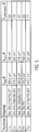
- Table in Fig. 5 shows an overview of the compression factors V compression that can be achieved with different gas bag materials.
- the compression factor V compression is calculated as follows:
- the package volume V real of the gas bag package is composed on the one hand of the volume of the gas bag material (gas bag volume V sack ) and on the other hand of the volume of air that is enclosed between the folds or between the fabric of the gas bag material.
- the air volume is referred to as the free space volume V free .
- the gas bag volume V bag can easily be calculated from the known density and the known weight per unit area of the gas bag materials used.
- the gas bag volume V bag thus corresponds substantially to a theoretical volume of tissue that would have the airbag packet 1, if it was completely free of air inclusions.
- the gas bag volume is shown in the table Fig. 5 referred to as "calculated theoretical fabric volume".
- the actual package volume V real is usually well above the value for the theoretically calculated airbag volume V sack .
- the package volume V real is shown in the table Fig. 5 referred to as "package volume”.
- the ratio between the package volume V real and the airbag volume V sack is relevant for assessing the packing density.
- This ratio (the compression factor) essentially indicates how many air inclusions still remain in the airbag package 1.
- a value that is as small as possible is sought in order to adapt the airbag package 1 for the smallest possible installation spaces.
- the invention also enables the airbag package to be permanently dimensionally stable independently. This is achieved as follows: Due to mechanical constraints, internal tensions arise in the tissue. At the microscopic level, these tensions are primarily due to the stiffness of the "tie molecules" in the amorphous area. This stiffness is due to energetic differences in the different cis-trans-gauche conformations of the chains and the secondary valence forces between the chains, i.e. through both intra- and intermolecular interactions.
- the method according to the invention now supplies the folded airbag with sufficient energy in a first step so that the "tie molecules" under tension move "more freely” in the amorphous region and the internal tensions are thereby reduced.
- energy is withdrawn from the system, so that the chains "freeze” in the new conformation.
- the entire airbag package thus remains independently in the specified form even after the external constraint has been removed.
- the tissue is in its initial state in its energetically most favorable arrangement, since there are no constraints; the CC bond angle is a tetrahedral angle.
- the folding or shaping of the tissue causes a bending of the molecules and thus a deviation from the tetrahedral angle; internal tensions arise in the molecule, so that without the external pressure of the molding press the tissue would spring back (rebound effect).
- the molecules are rotated by 120 ° or -120 ° around the longitudinal axis due to the thermal activation.
- the internal stresses are reduced, with the further consequence that the bond angles align again with tetrahedral angles.
- the compressed airbag package is cooled from the heating temperature to the final process temperature in a short time of less than 40 minutes, in particular less than 35 minutes, in particular less than 20 minutes, in particular less than 15 minutes, preferably within 10 minutes.
- the process end temperature i.e. the temperature at the end of the directed rapid cooling
- room temperature preferably more than 25 ° C, preferably more than 30 ° C, more preferably more than 35 ° C, in particular approx. 40 ° C amounts.
- Subsequent further cooling is conceivable, but without affecting the method according to the invention and the permanent dimensional stability of the airbag package.
Landscapes
- Engineering & Computer Science (AREA)
- Mechanical Engineering (AREA)
- Air Bags (AREA)
Description
- Die Erfindung betrifft ein Verfahren zur Herstellung eines Gassackpakets gemäß dem Oberbegriff des Patentanspruchs 1.
- Im Allgemeinen sind Gassackpakete aus einem gefalteten Gassack gebildet, der meist aus einem Textilgewebe hergestellt ist. Zwischen den Falten des Gassacks sowie den einzelnen Gewebefäden, also dem Material des Gassacks, sind im Gassackpaket Freiräume gebildet. Konkret besteht das Gassackpaket also aus dem gefalteten Gassack und einem gewissen Luftvolumen, das zwischen dem Material des Gassacks eingeschlossen ist.
- Bei der Herstellung eines Gassacks ist es bekannt, den Gassack zunächst zu falten und anschließend in eine Abdeckkappe zu übergeben. In der Abdeckkappe wird der Gassack fixiert, so dass er anschließend beispielsweise in ein Lenkrad oder Armaturenbrett eingesetzt werden kann. Die äußere Form des Gassackpakets ist allerdings nicht stabil, sondern fällt selbständig auseinander, wenn sie nicht in der Abdeckkappe fixiert ist. Diese Tendenz, sich wieder zu entfalten, weist das Gassackpaket auch nach dem Einsetzen in die Abdeckkappe auf. Folglich drückt das Gassackpaket während der gesamten Lebensdauer beständig gegen die Abdeckkappe. Diese Dauerbelastung zeichnet sich im Laufe der Zeit an der Aufreißkante der Abdeckkappe ab und beeinträchtigt das optische Erscheinungsbild der Abdeckkappe.
- Auch während der Herstellung führt die Instabilität des Gassackpakets zu Problemen. Bei dem Herstellungsverfahren gemäß
EP 1 127 752 A2 wird der Gassack mit Hilfe einer den Gassack umschließenden Folie gefaltet. Anschließend muss das Gassackpaket aus der Folie entnommen und in die Abdeckkappe übergeben werden. Zwar wird das Gassackpaket unter Temperatureinfluss gepresst, so dass die Faltung für einen begrenzten Zeitraum erhalten bleibt. Dennoch springt das Gassackpaket etwas auf, so dass das tatsächliche Paketvolumen aufgrund der darin eingeschlossenen Luft erheblich größer ist als das Gassackvolumen, das sich als theoretisches Gassackvolumen aus der Dichte des Materials errechnen lässt, welches für die Herstellung des Gassacks verwendet wird. Auch ist die Formgebung bei dem Herstellungsverfahren gemäßEP 1 127 752 A2 nicht dauerhaft. - Die
US 5,022,676 zeigt ein Verfahren zur Herstellung eines Gassackpakets, bei dem der Gassack ebenfalls zunächst erwärmt und gefaltet sowie anschließend im erhitzten Zustand zusammengepresst wird. Auf diese Weise wird eine relativ dauerhafte Formstabilität des Gassackpakets erreicht, wobei auf den damit erreichbaren Kompressionsgrad des Gassackpakets nicht näher eingegangen wird. - Die Aufgabe der Erfindung besteht darin, ein Verfahren zur Herstellung eines kompakten Gassackpakets anzugeben, bei dem das Gassackpacket seine Form dauerhaft beibehält.
- Erfindungsgemäß wird diese Aufgabe im Hinblick auf das Verfahren durch den Gegenstand des Anspruchs 1 gelöst.
- Die Erfindung betrifft ein Verfahren zur Herstellung eines Gassackpakets oder Insassenrückhaltesystems, insbesondere eines oben beschriebenen Gassackpakets oder Insassenrückhaltesystems, bei dem ein gefalteter Gassack in ein Formelement eingelegt und anschließend gepresst sowie gleichzeitig erwärmt wird, wobei das Pressen und Erwärmen des Gassacks zumindest solange durchgeführt wird, bis das Gassackpaket dauerhaft formstabil ist, und wobei nach dem Schritt des Erwärmens ein Schritt des Abkühlens des Gassacks auf eine Verfahrensendtemperatur um mindestens 100°C vorgesehen ist.
- Durch das gleichzeitige Pressen und Erwärmen wird ein Gassackpaket hergestellt, das im Wesentlichen ohne eine Volumenänderung in ein Gehäuse z.B. in eine Abdeckkappe übergeben werden kann. Das erleichtert die Herstellung des Gassackpakets erheblich und ermöglicht gleichzeitig die Produktion von Gassackpaketen mit möglichst kleinen Paketvolumina.
- Gemäß einer bevorzugten Ausgestaltung des erfindungsgemäßen Verfahrens weist das Formelement eine Innenkontur auf, die der Innenkontur eines Aufnahmeraums für das Gassackpaket im Insassenrückhaltesystem entspricht. Bei dem Verfahren wird in vorteilhafter Weise das Gassackpaket bereits in der Form gepresst und erwärmt, die es auch später im Insassenrückhaltesystem einnehmen soll. Da das Gassackpaket dauerhaft formstabil ist, wird vermieden, dass das Gassackpaket eine Kraft auf die Umhüllung des Aufnahmeraums, insbesondere eine Abdeckkappe, ausübt, die das optische Erscheinungsbild beeinträchtigen könnte.
- Das Pressen und Erwärmen des Gassacks wird vorzugsweise über einen Zeitraum von wenigstens einer Stunde, vorzugsweise etwa zwei Stunden, durchgeführt. Es hat sich gezeigt, dass dieser Zeitraum ausreicht, um ein dauerhaft formstabiles Gassackpaket herzustellen.
- Vorzugsweise wird der Gassack auf eine Temperatur von wenigstens 125° C, weiter vorzugweise wenigstens 140°, besonders vorzugsweise etwa 150°C, erwärmt. In Kombination mit dem gleichzeitigen Pressvorgang wird damit erreicht, dass im Material des Gassacks durch die Faltung eingebrachte innere Spannungen abgebaut werden. Somit stellt sich ein Gleichgewichtszustand ein, was dazu führt, dass das Gassackpaket die gewünschte Form beibehält. Insbesondere bleibt das Paketvolumen im Wesentlichen unverändert.
- Gemäß einem weiteren Aspekt des erfindungsgemäßen Verfahrens erfolgt das Erwärmen des Gassacks über einen Zeitraum von wenigstens einer Stunde, vorzugsweise etwa 2 Stunden.
- Gemäß einem weiteren Aspekt des erfindungsgemäßen Verfahrens erfolgt das Pressen bei einem Druck von wenigstens 50N/cm2, vorzugsweise bei einem Druck von wenigstens 80N/cm2, weiter vorzugsweise bei einem Druck von wenigstens 110N/cm2, und insbesondere bei einem Druck von größer gleich 130N/cm2.
- Es ist bevorzugt, dass nach dem Schritt des Erwärmens der Schritt des raschen Abkühlens des Gassackes auf eine Verfahrensendtemperatur um mindestens 110°C, vorzugsweise um mindestens 120°C, insbesondere um mindestens 125°C vorgesehen ist.
- Weiter ist bevorzugt, dass die Verfahrensendtemperatur über der Raumtemperatur liegt und/oder mehr als 25°C, vorzugsweise mehr als 30°C, weiter vorzugsweise mehr als 35°C insbesondere ca. 40°C beträgt.
- Gemäß einer weiter bevorzugten Ausgestaltung des erfindungsgemäßen Verfahrens ist vorgesehen, dass der Schritt des raschen Abkühlens des Gassackes auf die Verfahrensendtemperatur in kurzer Zeit von weniger als 20 Minuten, vorzugsweise innerhalb von 15 Minuten erfolgt.
- Ebenso ist bevorzugt, dass das Pressen des Gassackes während des Schrittes des Erwärmens und vorzugsweise auch während des Schrittes des raschen Abkühlens des Gassackes auf die Verfahrensendtemperatur erfolgt.
- Das Pressen des Gassacks kann mit einem Presselement durchgeführt werden, das auf einer auf den Gassack auflegbaren Kontaktfläche eine Erhebung aufweist. Die Erhebung drückt sich beim Pressen des Gassacks in eine Außenfläche des Gassackpakets ein, so dass im Gassackpaket eine Vertiefung gebildet wird. Diese Vertiefung kann beispielsweise genutzt werden, um den Raum für ein Emblem in einer Abdeckkappe freizuhalten.
- Die Erfindung wird im Folgenden anhand von Ausführungsbeispielen unter Bezugnahme auf die beigefügten, schematischen Zeichnungen näher erläutert. Darin zeigen
- Fig. 1:
- ein Formelement für die erfindungsgemäße Herstellung eines Gassackpakets nach einem bevorzugten Ausführungsbeispiel;
- Fig. 2:
- das Formelement gemäß
Fig. 1 , wobei ein Presselement zum Pressen des gefalteten Gassacks eingesetzt ist; - Fig. 3:
- das Formelement gemäß
Fig. 1 mit abgenommenem Press-element nach dem Pressen des Gassacks; - Fig. 4:
- ein Gassackpaket nach dem Pressen gemäß den in den
Fig. 1-3 gezeigten Schritten im formstabilen Zustand; - Fig. 5:
- eine tabellarische Übersicht von Kompressionsverhältnissen Vreal/VSack bei unterschiedlichen Gassackmaterialien;
- Fig. 6
- ein Diagramm, das das Relaxationsverhalten eines gemäß dem erfindungsgemäßen Verfahren hergestellten Gassackpakets über Druck und Zeit darstellt; und
- Fig. 7a - d
- die vier Phasen der Gewebemoleküle eines nach dem erfindungsgemäßen Verfahren in dauerhaft stabile Form gebrachten Gassackpaketes.
- In
Fig. 1 ist ein nach oben geöffneter Container gezeigt, der das Formelement 5 für die Herstellung des erfindungsgemäßen Gassacks 2 bildet. Das Formelement 5 weist eine Innenkontur bzw. eine Innengeometrie auf, die der Innenkontur bzw. der Innengeometrie eines Aufnahmeraums entspricht, in welchen das Gassackpaket 1 im Insassenrückhaltesystem angeordnet ist. Der Aufnahmeraum ist üblicherweise in einer Abdeckkappe eines Airbagmoduls angeordnet. Gut zu erkennen sind zwei gegenüberliegende, schlitzartige Öffnungen 8 in den Seitenwänden des Formelements 5. Diese dienen zum Fixieren eines Presselements 6, das bei der Herstellung des Gassackpakets 1 zum Einsatz kommt. - Im Folgenden werden die einzelnen Schritte des Herstellungsverfahrens näher erläutert:
Zunächst wird der Gassack 2 gefaltet und im gefalteten Zustand in das Formelement 5 übergeben. Anschließend wird das Presselement 6, das vorzugsweise eine der Innenkontur des Formelements 5 entsprechende Außenkontur aufweist, in das Formelement 5 eingesetzt (Fig. 2 ). Das Presselement 6 weist einen Sperrbalken 7 auf, der in die schlitzartigen Öffnungen 8 des Formelements 5 eingreift. Der Sperrbalken 7 ist mit einer Schraube 9 am Presselement 6 fixiert. Das Formelement 5 und das Presselement 6 wirken derart zusammen, dass auf den gefalteten Gassack 2 eine Presskraft von etwa 10900 N aufgebracht wird. - Gleichzeitig mit dem Pressen des Gassacks 2 wird das im Formelement 5 angeordnete Gassackpaket 1 mit Wärme beaufschlagt. Das Gassackpaket 1 dabei auf eine Temperatur von über 130°C, vorzugsweise auf über 140°C erwärmt. Insbesondere ist vorgesehen, dass das Gassackpaket 1 dabei auf eine Temperatur von 150° C erwärmt wird. Das Pressen und Erwärmen des Gassackpakets 1 erfolgt über einen Zeitraum etwa zwei Stunden, so dass sich die inneren Spannungen im Gassackgewebe bzw. im Material des Gassacks 2 abbauen. Somit behält das Gassackpaket 1 seine Form bei, auch wenn es aus dem Formelement 5 herausgelöst ist.
-
Fig. 3 zeigt das im Formelement 5 angeordnete Gassackpaket 1 nach dem Vorgang des Pressens und Erwärmens. - Hieran schließt sich noch ein Schritt des raschen Abkühlens des Gassackpacketes um mindestens 80°C, vorzugsweises mindestens 90°C, weiter vorzugsweise mindestens 100°C, insbesondere mindestens 110°C, wobei gemäß einer besonderen Ausführungsform auch ein Abkühlen um mindestens 120°C oder mindestens 125°C möglich ist.
- Gemäß einer speziell bevorzugten Ausführung erfolgt das Abkühlen von einer Haltetemperatur von 150°C auf eine Verfahrensendtemperatur von 40°C.
- Das Abkühlen des gepreßten Gassackpaketes von der Erwärmungstemperatur auf die Verfahrensendtemperatur erfolgt erfindungsgemäß in kurzer Zeit von weniger als 25 Minuten, insbesondere von weniger als 20 Minuten, vorzugsweise innerhalb von 15 Minuten.
- Das gepresste und abgekühlte Gassackpaket 1 kann nun aus dem Formelement 5 entnommen werden und weist eine dauerhaft stabile Form auf (
Fig. 4 ). - Bei dem hier gezeigten Ausführungsbeispiel ist ferner vorgesehen, dass das Presselement 6 eine Erhebung aufweist, die beim Pressen des Gassackpakets 1 eine Vertiefung 4 auf einer Außenfläche 3 des Gassackpakets hinterlässt. Die Vertiefung 4 dient beispielsweise dazu, einen Emblemraum eines Fahrzeugemblems in einer Abdeckkappe freizuhalten.
- Die Besonderheit des auf diese Weise hergestellten Gassackpakets zeigt sich im Kompressionsfaktor, der deutlich niedriger ist als bei bekannten Gassackpaketen. Der Kompressionsfaktor entspricht dem Verhältnis zwischen Paketvolumen Vreal und Gassackvolumen Vsack gemäß dem Quotienten Vreal/Vsack. Tabelle in
Fig. 5 zeigt eine Übersicht über die erreichbaren Kompressionsfaktoren Vcompression bei unterschiedlichen Gassackmaterialien. - Der Kompressionsfaktor Vcompression berechnet sich wie folgt:
Das Paketvolumen Vreal des Gassackpakets setzt sich einerseits aus dem Volumen des Gassackmaterials (Gassackvolumen VSack) und andererseits aus dem Luftvolumen zusammen, das zwischen den Falten bzw. zwischen dem Gewebe des Gassackmaterials eingeschlossen ist. Das Luftvolumen wird als Freiraumvolumen Vfrei bezeichnet. - Das Gassackvolumen VSack kann ohne Weiteres aus der bekannten Dichte und dem bekannten Flächengewicht der verwendeten Gassackmaterialien errechnet werden. Das Gassackvolumen VSack entspricht somit im Wesentlichen einem theoretischen Gewebevolumen, das das Gassackpaket 1 aufweisen würde, wenn es vollständig frei von Lufteinschlüssen wäre. Das Gassackvolumen ist in der Tabelle gemäß
Fig. 5 als "calculated theoretical fabric volume" bezeichet. - Das tatsächliche Paketvolumen Vreal liegt üblicherweise deutlich über dem Wert für das theoretisch errechnete Gassackvolumen VSack. Das Paketvolumen Vreal ist in der Tabelle gemäß
Fig. 5 als "package volume" bezeichnet. - Für die Beurteilung der Packungsdichte ist das Verhältnis zwischen dem Paketvolumen Vreal und dem Gassackvolumen Vsack relevant. Dieses Verhältnis (der Kompressionsfaktor) gibt im Wesentlichen an, wie viel Lufteinschlüsse noch im Gassackpaket 1 verbleiben. Ein möglichst kleiner Wert wird angestrebt, um das Gassackpaket 1 für möglichst kleine Einbauräume anzupassen.
- Mit dem erfindungsgemäßen Verfahren sind verhältnismäßig große Kompressionsfaktoren realisierbar, wie die Tabelle in
Fig. 5 anschaulich zeigt. Konkret sind mit dem erfindungsgemäßen Verfahren reale Paketvolumina Vreal erreichbar, die um maximal das 1,8-fache größer als ein theoretisches Gassackvolumen VSack sind, das aus der Dichte des verwendeten Gassackgewebes bzw. Gassackmaterials errechnet wird. Dabei wird angenommen, dass das verwendete Gassackmaterial nicht als Gewebe mit Lufteinschlüssen bzw. Freiräumen vorliegt, sondern als kompakter Materialblock aus dem Gewebematerial des Gassacks 2. Der Materialblock ist also Lufteinschlussfrei. - Die Erfindung ermöglicht daneben auch, dass das Gassackpaket selbstständig dauerhaft formstabil ist. Dies wird folgendermaßen erreicht: Durch mechanische Zwangsbedingungen entstehen innere Spannungen im Gewebe. Auf mikroskopischer Ebene sind diese Spannungen primär bedingt durch die Steifheit der "tie-Moleküle" im amorphen Bereich. Diese Steifheit ist bedingt durch energetische Unterschiede in den unterschiedlichen cis-trans-gauche-Konformation der Ketten und den Nebenvalenzkräfte zwischen den Ketten, d.h. sowohl durch intra- als auch intermolekulare Wechselwirkungen.
- Das erfindungsgemäße Verfahren führt nun dem gefalteten Luftsack in einem ersten Schritt hinreichend viel Energie zu, so dass sich die unter Spannung stehenden "tie-Moleküle" im amorphen Bereich "freier bewegen" und die inneren Spannungen dadurch abgebaut werden. In einem zweiten Schritt wird nun wieder Energie aus dem System entzogen, so dass die Ketten in der neuen Konformation "einfrieren". Das gesamte Luftsackpaket bleibt dadurch auch nach Wegnahme der äußeren Zwangsbedingung selbstständig in der vorgegebenen Form.
- Die
Figuren 7a bis 7d zeigen die vier Phasen der Gewebemoleküle eines nach dem erfindungsgemäßen Verfahren in dauerhaft stabile Form gebrachten Gassackpaketes, wobei inFig. 7a das Gewebe vor der Bearbeitung gezeigt ist, inFigur 7b das Gewebe gefaltet und in Form gepresst dargestellt ist, inFigur 7c das Gewebe nach einer Erwärmung auf T=150°C gezeigt ist, und inFigur 7d das Gewebe zwei Stunden später nach der Abkühlung auf T=40°C dargestellt ist. - Wie in
Fig. 7a dargestellt, befindet sich das Gewebe in seinem Ausgangszustand in seiner energetisch günstigsten Anordnung, da Zwangsbedingung fehlen; der C-C Bindungswinkel ist ein Tetraederwinkel. - Wie in
Fig. 7b dargestellt, bewirkt das Falten bzw. Formen des Gewebes eine Biegung der Moleküle und somit eine Abweichung vom Tetraederwinkel; es entstehen innere Spannungen im Molekül, so dass ohne den äußeren Zwang der Formpresse das Gewebe zurückfedern würde (Rebound Effect). - Wie in
Fig. 7c dargestellt, erfolgt eine Drehung der Moleküle um 120° bzw. -120° um Längsachse aufgrund der thermischen Aktivierung. Es erfolgt also über die Zeit ein Abbau der inneren Spannungen mit der weiteren Folge, dass sich die Bindungswinkel sich wieder Tetraederwinkeln angleichen. - Wie schließlich in
Fig. 7d dargestellt, ist die neue Konformation bei vorgegebener Zwangsbedingung (Gassackpaket gefaltet im Container) die energetisch günstigste. Die rasche Abkühlung deaktiviert die fortgesetzte Drehung der Moleküle, so dass das Gassackpaket Paket thermisch fixiert ist und sich auch nach einer Entfernung des Zwangs dauerhaft nicht mehr entfaltet. - Hierzu wurden Versuche durchgeführt, die bestätigen, dass es erfindungsgemäß möglich ist, das Gassackpaket selbstständig dauerhaft formstabil zu erzeugen: Hierbei wurde ein in Form gebrachtes Gassackpaket im kalten Zustand in einen auf 150°C aufgewärmten Ofen eingebracht. Der zur Formgebung verwendete Pressstempel wurde innerhalb ca. 60s-90s mit 10000N belastet. Die dabei erreichte Stempelposition wurde dann über den gesamten Versuch konstant gehalten. In diesem Zustand wurde für 2h = 7200 s die wirkende Kraft auf den Stempel registriert. Zur besseren Überschaubarkeit des Temperaturverlaufs wurde die Temperatur im inneren des Airbags mit einem Thermoelement gemessen. Im Anschluss der 2h bei 150°C wurde mittels flüssigem Stickstoff (In2) der Ofen bzw. die Vorrichtung mit Airbag abgekühlt. Die Ergebnisse sind in
Figur 6 zusammengestellt, die den Verlauf der Druckkraft und der Temperatur während des Versuchs wiedergibt. - Es zeigt sich, dass In den ersten Minuten der größte Kraftabbau stattfindet. Mit dem Erreichen der Glasübergangstemperatur(en) ist eine schnelle Relaxation der Druckkraft bis zum Ausfüllen vorhandener "Hohlräume" gegeben. Durch Abkühlen verringert sich die wirkende Druckkraft. Beim Erreichen der Innentemperatur von ca. 50°C - 60°C ist die Druckkraft kleiner als 100N.
- Das Abkühlen des gepreßten Gassackpaketes von der Erwärmungstemeratur auf die Verfahrensendtemperatur erfolgt erfindungsgemäß in kurzer Zeit von weniger als 40 Minuten, insbesondere von weniger als 35 Minuten, insbesondere von weniger als 20 Minuten, insbesondere von weniger als 15 Minuten, vorzugsweise innerhalb von 10 Minuten.
- Es ist vorgesehen, dass die Verfahrensendtemperatur, also die Temperatur am Ende des gerichteten raschen Abkühlens über der Raumtemperatur liegt und/oder mehr als 25°C, vorzugsweise mehr als 30°C, weiter vorzugsweise mehr als 35°C insbesondere ca. 40°C beträgt. Ein nachfolgendes weiteres Abkühlen ist denkbar, jedoch ohne Einfluß auf das erfindungsgemäße Verfahren und die Dauerhafte Formstabilität des Gassackpacketes.
-
- 1
- Gassackpaket
- 2
- Gassack
- 3
- Außenfläche
- 4
- Vertiefung
- 5
- Formelement
- 6
- Presselement
- 7
- Sperrbalken
- 8
- Öffnung
- 9
- Schraube
Claims (10)
- Verfahren zur Herstellung eines Gassackpakets (1) oder eines Insassenrückhaltesystems mit einem Gassackpaket (1), bei dem ein gefalteter Gassack (2) in ein Formelement (5) eingelegt und anschließend gepresst sowie erwärmt wird, wobei das Pressen des Gassacks (2) zumindest solange durchgeführt wird, bis das Gassackpaket (1) im Wesentlichen selbstständig dauerhaft formstabil ist,
dadurch gekennzeichnet, dass zur thermischen Fixierung des Gassackpakets (1) nach dem Schritt des Erwärmens ein Schritt des Abkühlens des Gassackes (2) auf eine Verfahrensendtemperatur in kurzer Zeit von weniger als 35 Minuten um mindestens 100°C vorgesehen ist. - Verfahren nach Anspruch 1, dadurch gekennzeichnet, dass der Gassack (2) auf eine Temperatur von wenigstens 125°C, vorzugweise wenigstens 140°, insbesondere etwa 150°C, erwärmt wird.
- Verfahren nach Anspruch 1 oder 2, dadurch gekennzeichnet, dass das Erwärmen des Gassacks (2) über einen Zeitraum von wenigstens einer Stunde, vorzugsweise etwa 2 Stunden, durchgeführt wird.
- Verfahren nach einem der vorhergehenden Ansprüche, dadurch gekennzeichnet, dass das Pressen bei einem Druck von wenigstens 50 N/cm2, vorzugsweise bei einem Druck von wenigstens 80 N/cm2, weiter vorzugsweise bei einem Druck von wenigstens 110 N/cm2, und insbesondere bei einem Druck von größer gleich 130 N/cm2 erfolgt.
- Verfahren nach einem der vorhergehenden Ansprüche, dadurch gekennzeichnet, dass der Schritt des Abkühlens des Gassackes (2) auf eine Verfahrensendtemperatur um mindestens 110°C, vorzugsweise um mindestens 120°C, insbesondere um mindestens 125°C vorgesehen ist.
- Verfahren nach Anspruch 5, dadurch gekennzeichnet, dass die Verfahrensendtemperatur über der Raumtemperatur liegt und/oder mehr als 25°C, vorzugsweise mehr als 30°C, weiter vorzugsweise mehr als 35°C insbesondere ca. 40°C beträgt.
- Verfahren nach einem der vorhergehenden Ansprüche, dadurch gekennzeichnet, dass der Schritt des Abkühlens des Gassackes (2) auf die Verfahrensendtemperatur in kurzer Zeit von weniger als 20 Minuten, vorzugsweise innerhalb von 15 Minuten erfolgt.
- Verfahren nach einem der vorhergehenden Ansprüche, dadurch gekennzeichnet, dass das Pressen des Gassackes (2) auch während des Schrittes des Abkühlens des Gassackes (2) auf die Verfahrensendtemperatur erfolgt.
- Verfahren nach einem der vorhergehenden Ansprüche, dadurch gekennzeichnet, dass das Formelement (5) eine Innenkontur aufweist, die der Innenkontur eines Aufnahmeraums für das Gassackpaket (1) im Insassenrückhaltesystem entspricht.
- Verfahren nach einem der vorhergehenden Ansprüche, dadurch gekennzeichnet, dass das Pressen des Gassacks (2) mit einem Presselement (6) durchgeführt wird, das auf einer auf den Gassack (2) auflegbaren Kontaktfläche eine Erhebung aufweist.
Applications Claiming Priority (2)
| Application Number | Priority Date | Filing Date | Title |
|---|---|---|---|
| DE102012008809A DE102012008809A1 (de) | 2012-05-07 | 2012-05-07 | Gassackpaket für ein insassenrückhaltesystem eines kraftfahrzeugs, insassenrückhaltesystem und verfahren zur herstellung eines derartigen gassackpakets |
| PCT/EP2013/001343 WO2013167261A1 (de) | 2012-05-07 | 2013-05-07 | Gassackpaket für ein insassenrückhaltesystem eines kraftfahrzeugs, insassenrückhaltesystem und verfahren zur herstellung eines derartigen gassackpakets |
Publications (2)
| Publication Number | Publication Date |
|---|---|
| EP2847046A1 EP2847046A1 (de) | 2015-03-18 |
| EP2847046B1 true EP2847046B1 (de) | 2020-09-16 |
Family
ID=48577674
Family Applications (1)
| Application Number | Title | Priority Date | Filing Date |
|---|---|---|---|
| EP13727514.5A Active EP2847046B1 (de) | 2012-05-07 | 2013-05-07 | Gassackpaket für ein insassenrückhaltesystem eines kraftfahrzeugs, insassenrückhaltesystem und verfahren zur herstellung eines derartigen gassackpakets |
Country Status (6)
| Country | Link |
|---|---|
| US (1) | US9333933B2 (de) |
| EP (1) | EP2847046B1 (de) |
| JP (2) | JP2015520065A (de) |
| CN (1) | CN104271408B (de) |
| DE (1) | DE102012008809A1 (de) |
| WO (1) | WO2013167261A1 (de) |
Families Citing this family (8)
| Publication number | Priority date | Publication date | Assignee | Title |
|---|---|---|---|---|
| US9180919B2 (en) * | 2013-06-18 | 2015-11-10 | Thomas Scott Breidenbach | Aerodynamic drag reducing apparatus |
| DE102015010789A1 (de) * | 2015-08-20 | 2017-02-23 | Trw Automotive Gmbh | Verfahren zum Zusammenlegen eines Gassacks, Pressvorrichtung zum Formen von Gassackpaketen sowie Gassackpaket |
| JP6508011B2 (ja) | 2015-11-13 | 2019-05-08 | 豊田合成株式会社 | エアバッグ装置とその製造方法 |
| JP6424799B2 (ja) * | 2015-11-13 | 2018-11-21 | 豊田合成株式会社 | エアバッグ折畳体の製造方法 |
| DE102017203931B4 (de) | 2017-03-09 | 2021-05-20 | Joyson Safety Systems Germany Gmbh | Verfahren zum Herstellen eines Gassackmoduls eines Fahrzeuginsassen-Rückhaltesystems |
| EP3446932B1 (de) | 2017-08-21 | 2019-12-18 | Autoliv Development AB | Verbesserungen an oder im zusammenhang mit dem falten von airbags |
| DE102018220930A1 (de) | 2017-12-27 | 2019-06-27 | Key Safety Systems, Inc. | Verfahren zur Herstellung eines Airbag-Minipacks |
| US11001223B2 (en) | 2017-12-27 | 2021-05-11 | Key Safety Systems, Inc. | Method of manufacturing an airbag mini-pack |
Family Cites Families (12)
| Publication number | Priority date | Publication date | Assignee | Title |
|---|---|---|---|---|
| DE1031473B (de) * | 1954-06-16 | 1958-06-04 | Seibel Metallhuettenwerk W | Drehofen mit nicht kreisfoermigem Querschnitt zum Einschmelzen von Metallen |
| US5022676A (en) * | 1990-01-25 | 1991-06-11 | Allied-Signal Inc. | Air bag assembly and method therefor |
| JPH09254733A (ja) * | 1996-03-26 | 1997-09-30 | Toyota Motor Corp | エアバッグ袋体形状保持装置 |
| JPH1044905A (ja) * | 1996-08-06 | 1998-02-17 | Takata Kk | 樹脂製エアバッグ |
| DE19908610A1 (de) * | 1999-02-27 | 2000-08-31 | Bayerische Motoren Werke Ag | Verfahren und Vorrichtung zum Verpacken eines Luftsackes für einen Airbagmodul |
| DE10009333A1 (de) | 2000-02-28 | 2001-08-30 | Trw Repa Gmbh | Verfahren zum Überführen eines Gassacks für ein Fahrzeuginsassen-Rückhaltesystem in eine für den Gassack vorgesehene Aufnahme |
| JP2006176076A (ja) * | 2004-12-24 | 2006-07-06 | Takata Corp | エアバッグ塊、その形成方法及びエアバッグ装置 |
| JP4877733B2 (ja) * | 2005-12-28 | 2012-02-15 | タカタ株式会社 | エアバッグモジュールの製造方法 |
| DE102006055037B4 (de) * | 2006-11-22 | 2018-10-04 | Trw Automotive Gmbh | Verfahren zum Zusammenlegen eines Gassacks und zusammengelegter Gassack |
| DE102009033561A1 (de) * | 2009-07-16 | 2011-01-20 | Autoliv Development Ab | Verfahren zur Faltung eines Gassackes für ein Airbagmodul für ein Kraftfahrzeug, ein Airbagmodul und eine Vorrichtung zur Faltung eines Gassackes für ein Airbagmodul |
| DE102009059702B4 (de) * | 2009-12-18 | 2020-03-12 | Autoliv Development Ab | Gassack |
| EP2594441B1 (de) * | 2011-11-15 | 2014-06-18 | Autoliv Development AB | Verfahren zum Verpacken eines Airbags |
-
2012
- 2012-05-07 DE DE102012008809A patent/DE102012008809A1/de active Pending
-
2013
- 2013-05-07 EP EP13727514.5A patent/EP2847046B1/de active Active
- 2013-05-07 US US14/395,543 patent/US9333933B2/en active Active
- 2013-05-07 WO PCT/EP2013/001343 patent/WO2013167261A1/de not_active Ceased
- 2013-05-07 JP JP2015510678A patent/JP2015520065A/ja active Pending
- 2013-05-07 CN CN201380024033.3A patent/CN104271408B/zh active Active
-
2017
- 2017-11-15 JP JP2017219878A patent/JP2018047901A/ja active Pending
Non-Patent Citations (1)
| Title |
|---|
| None * |
Also Published As
| Publication number | Publication date |
|---|---|
| DE102012008809A1 (de) | 2013-11-07 |
| CN104271408B (zh) | 2017-08-08 |
| EP2847046A1 (de) | 2015-03-18 |
| WO2013167261A1 (de) | 2013-11-14 |
| US20150130167A1 (en) | 2015-05-14 |
| JP2018047901A (ja) | 2018-03-29 |
| JP2015520065A (ja) | 2015-07-16 |
| US9333933B2 (en) | 2016-05-10 |
| CN104271408A (zh) | 2015-01-07 |
Similar Documents
| Publication | Publication Date | Title |
|---|---|---|
| WO2013167261A1 (de) | Gassackpaket für ein insassenrückhaltesystem eines kraftfahrzeugs, insassenrückhaltesystem und verfahren zur herstellung eines derartigen gassackpakets | |
| DE102009059702B4 (de) | Gassack | |
| WO2017029388A1 (de) | Verfahren zum zusammenlegen eines gassacks, pressvorrichtung zum formen von gassackpaketen sowie gassackpaket | |
| DE10030790C1 (de) | Halbzeug aus einer Formgedächtnislegierung mit Zweiwegeffekt und Verfahren zum Herstellen desselben | |
| EP2454128B1 (de) | Verfahren zur faltung eines gassackes für ein airbagmodul für ein kraftfahrzeug, ein airbagmodul und eine vorrichtung zur faltung eines gassackes für ein airbagmodul | |
| CH653369A5 (de) | Verbundwerkstoff in stab-, rohr-, band-, blech- oder plattenform mit reversiblen thermo-mechanischen eigenschaften und verfahren zu dessen herstellung. | |
| CH629382A5 (de) | Verfahren zum herstellen eines formstabilen absorbierenden koerpers aus gepressten zellulosefasern. | |
| EP0839691B1 (de) | Verfahren zum Falten eines Gassacks für ein Fahrzeuginsassen-Rückhaltesystem, gefalteter Gassack für ein Fahrzeuginsassen-Rückhaltesystem sowie Vorrichtung zur Durchführung des Verfahrens | |
| DE69802516T2 (de) | Verfahren zum Herstellen von Rastnuten in Rohren, sowie durch das Verfahren hergestellten Rohre | |
| DE102007005517A1 (de) | Überrollschutzsystem für Kraftfahrzeuge mit einem aktiv aufstellbaren Überrollkörper | |
| DE112018004051T5 (de) | Gasgenerator mit drosselelement | |
| DE1627707A1 (de) | Verfahren zur Herstellung eines Metallformstueckes | |
| DE4315289A1 (de) | Verfahren zum Herstellen von Metallteilen durch Freiformschmieden und Schmieden in einer Presse | |
| DE102013017644B4 (de) | Verfahren zum Herstellen einer mehrdimensional strukturierten Materialbahn und Verwendung derselben | |
| EP1179455B9 (de) | Verfahren zur Faltung eines Gassacks und Vorrichtung zur Durchführung des Verfahrens | |
| DE102015108423A1 (de) | Gassack für ein Airbagmodul | |
| DE102006055037B4 (de) | Verfahren zum Zusammenlegen eines Gassacks und zusammengelegter Gassack | |
| DE102011016676B4 (de) | Verfahren zur Herstellung eines kompakten Gassackpakets sowie Gassackmodul mit einem derart hergestellten Gassackpaket | |
| EP2064404A1 (de) | Ver- und entriegelungsvorrichtung | |
| EP3406366A1 (de) | Verfahren zum herstellen eines federblatts, federblatt für eine blattfeder, blattfeder für eine radaufhängung eines kraftfahrzeuges. | |
| EP1293395B1 (de) | Verfahren zum Falten eines Gassacks für ein Fahrzeuginsassen-Rückhaltesystem sowie gefalteter Gassack | |
| DE19781835B4 (de) | Verfahren zum Herstellen eines Überrollbügels und Überrollbügel | |
| DE3844164C2 (de) | ||
| DE10045344B4 (de) | Gassack | |
| DE19603035C2 (de) | Verfahren und Vorrichtung zur Herstellung von Halbzeugen |
Legal Events
| Date | Code | Title | Description |
|---|---|---|---|
| PUAI | Public reference made under article 153(3) epc to a published international application that has entered the european phase |
Free format text: ORIGINAL CODE: 0009012 |
|
| 17P | Request for examination filed |
Effective date: 20141208 |
|
| AK | Designated contracting states |
Kind code of ref document: A1 Designated state(s): AL AT BE BG CH CY CZ DE DK EE ES FI FR GB GR HR HU IE IS IT LI LT LU LV MC MK MT NL NO PL PT RO RS SE SI SK SM TR |
|
| AX | Request for extension of the european patent |
Extension state: BA ME |
|
| DAX | Request for extension of the european patent (deleted) | ||
| STAA | Information on the status of an ep patent application or granted ep patent |
Free format text: STATUS: EXAMINATION IS IN PROGRESS |
|
| 17Q | First examination report despatched |
Effective date: 20170725 |
|
| TPAC | Observations filed by third parties |
Free format text: ORIGINAL CODE: EPIDOSNTIPA |
|
| RAP1 | Party data changed (applicant data changed or rights of an application transferred) |
Owner name: ZF AUTOMOTIVE SAFETY GERMANY GMBH |
|
| GRAP | Despatch of communication of intention to grant a patent |
Free format text: ORIGINAL CODE: EPIDOSNIGR1 |
|
| STAA | Information on the status of an ep patent application or granted ep patent |
Free format text: STATUS: GRANT OF PATENT IS INTENDED |
|
| RIN1 | Information on inventor provided before grant (corrected) |
Inventor name: HEROLD, TIMM Inventor name: HEPP, STEFAN Inventor name: SAPOUNTZIS, STEFAN Inventor name: BACHMANN, STEFAN Inventor name: FREUDENBERGER, KLAUS Inventor name: RUMPF, DIETER Inventor name: KUNKEL, MICHAEL Inventor name: HIRZMANN, GUIDO |
|
| INTG | Intention to grant announced |
Effective date: 20200428 |
|
| GRAS | Grant fee paid |
Free format text: ORIGINAL CODE: EPIDOSNIGR3 |
|
| GRAA | (expected) grant |
Free format text: ORIGINAL CODE: 0009210 |
|
| STAA | Information on the status of an ep patent application or granted ep patent |
Free format text: STATUS: THE PATENT HAS BEEN GRANTED |
|
| AK | Designated contracting states |
Kind code of ref document: B1 Designated state(s): AL AT BE BG CH CY CZ DE DK EE ES FI FR GB GR HR HU IE IS IT LI LT LU LV MC MK MT NL NO PL PT RO RS SE SI SK SM TR |
|
| REG | Reference to a national code |
Ref country code: GB Ref legal event code: FG4D Free format text: NOT ENGLISH |
|
| REG | Reference to a national code |
Ref country code: CH Ref legal event code: EP |
|
| REG | Reference to a national code |
Ref country code: DE Ref legal event code: R096 Ref document number: 502013015134 Country of ref document: DE |
|
| REG | Reference to a national code |
Ref country code: IE Ref legal event code: FG4D Free format text: LANGUAGE OF EP DOCUMENT: GERMAN |
|
| REG | Reference to a national code |
Ref country code: AT Ref legal event code: REF Ref document number: 1313905 Country of ref document: AT Kind code of ref document: T Effective date: 20201015 |
|
| PG25 | Lapsed in a contracting state [announced via postgrant information from national office to epo] |
Ref country code: FI Free format text: LAPSE BECAUSE OF FAILURE TO SUBMIT A TRANSLATION OF THE DESCRIPTION OR TO PAY THE FEE WITHIN THE PRESCRIBED TIME-LIMIT Effective date: 20200916 Ref country code: GR Free format text: LAPSE BECAUSE OF FAILURE TO SUBMIT A TRANSLATION OF THE DESCRIPTION OR TO PAY THE FEE WITHIN THE PRESCRIBED TIME-LIMIT Effective date: 20201217 Ref country code: NO Free format text: LAPSE BECAUSE OF FAILURE TO SUBMIT A TRANSLATION OF THE DESCRIPTION OR TO PAY THE FEE WITHIN THE PRESCRIBED TIME-LIMIT Effective date: 20201216 Ref country code: SE Free format text: LAPSE BECAUSE OF FAILURE TO SUBMIT A TRANSLATION OF THE DESCRIPTION OR TO PAY THE FEE WITHIN THE PRESCRIBED TIME-LIMIT Effective date: 20200916 Ref country code: BG Free format text: LAPSE BECAUSE OF FAILURE TO SUBMIT A TRANSLATION OF THE DESCRIPTION OR TO PAY THE FEE WITHIN THE PRESCRIBED TIME-LIMIT Effective date: 20201216 Ref country code: HR Free format text: LAPSE BECAUSE OF FAILURE TO SUBMIT A TRANSLATION OF THE DESCRIPTION OR TO PAY THE FEE WITHIN THE PRESCRIBED TIME-LIMIT Effective date: 20200916 |
|
| REG | Reference to a national code |
Ref country code: NL Ref legal event code: MP Effective date: 20200916 |
|
| PG25 | Lapsed in a contracting state [announced via postgrant information from national office to epo] |
Ref country code: LV Free format text: LAPSE BECAUSE OF FAILURE TO SUBMIT A TRANSLATION OF THE DESCRIPTION OR TO PAY THE FEE WITHIN THE PRESCRIBED TIME-LIMIT Effective date: 20200916 Ref country code: RS Free format text: LAPSE BECAUSE OF FAILURE TO SUBMIT A TRANSLATION OF THE DESCRIPTION OR TO PAY THE FEE WITHIN THE PRESCRIBED TIME-LIMIT Effective date: 20200916 |
|
| REG | Reference to a national code |
Ref country code: LT Ref legal event code: MG4D |
|
| PG25 | Lapsed in a contracting state [announced via postgrant information from national office to epo] |
Ref country code: RO Free format text: LAPSE BECAUSE OF FAILURE TO SUBMIT A TRANSLATION OF THE DESCRIPTION OR TO PAY THE FEE WITHIN THE PRESCRIBED TIME-LIMIT Effective date: 20200916 Ref country code: SM Free format text: LAPSE BECAUSE OF FAILURE TO SUBMIT A TRANSLATION OF THE DESCRIPTION OR TO PAY THE FEE WITHIN THE PRESCRIBED TIME-LIMIT Effective date: 20200916 Ref country code: LT Free format text: LAPSE BECAUSE OF FAILURE TO SUBMIT A TRANSLATION OF THE DESCRIPTION OR TO PAY THE FEE WITHIN THE PRESCRIBED TIME-LIMIT Effective date: 20200916 Ref country code: PT Free format text: LAPSE BECAUSE OF FAILURE TO SUBMIT A TRANSLATION OF THE DESCRIPTION OR TO PAY THE FEE WITHIN THE PRESCRIBED TIME-LIMIT Effective date: 20210118 Ref country code: NL Free format text: LAPSE BECAUSE OF FAILURE TO SUBMIT A TRANSLATION OF THE DESCRIPTION OR TO PAY THE FEE WITHIN THE PRESCRIBED TIME-LIMIT Effective date: 20200916 Ref country code: CZ Free format text: LAPSE BECAUSE OF FAILURE TO SUBMIT A TRANSLATION OF THE DESCRIPTION OR TO PAY THE FEE WITHIN THE PRESCRIBED TIME-LIMIT Effective date: 20200916 Ref country code: EE Free format text: LAPSE BECAUSE OF FAILURE TO SUBMIT A TRANSLATION OF THE DESCRIPTION OR TO PAY THE FEE WITHIN THE PRESCRIBED TIME-LIMIT Effective date: 20200916 |
|
| PG25 | Lapsed in a contracting state [announced via postgrant information from national office to epo] |
Ref country code: IS Free format text: LAPSE BECAUSE OF FAILURE TO SUBMIT A TRANSLATION OF THE DESCRIPTION OR TO PAY THE FEE WITHIN THE PRESCRIBED TIME-LIMIT Effective date: 20210116 Ref country code: PL Free format text: LAPSE BECAUSE OF FAILURE TO SUBMIT A TRANSLATION OF THE DESCRIPTION OR TO PAY THE FEE WITHIN THE PRESCRIBED TIME-LIMIT Effective date: 20200916 Ref country code: AL Free format text: LAPSE BECAUSE OF FAILURE TO SUBMIT A TRANSLATION OF THE DESCRIPTION OR TO PAY THE FEE WITHIN THE PRESCRIBED TIME-LIMIT Effective date: 20200916 Ref country code: ES Free format text: LAPSE BECAUSE OF FAILURE TO SUBMIT A TRANSLATION OF THE DESCRIPTION OR TO PAY THE FEE WITHIN THE PRESCRIBED TIME-LIMIT Effective date: 20200916 |
|
| REG | Reference to a national code |
Ref country code: DE Ref legal event code: R097 Ref document number: 502013015134 Country of ref document: DE |
|
| PG25 | Lapsed in a contracting state [announced via postgrant information from national office to epo] |
Ref country code: SK Free format text: LAPSE BECAUSE OF FAILURE TO SUBMIT A TRANSLATION OF THE DESCRIPTION OR TO PAY THE FEE WITHIN THE PRESCRIBED TIME-LIMIT Effective date: 20200916 |
|
| PLBE | No opposition filed within time limit |
Free format text: ORIGINAL CODE: 0009261 |
|
| STAA | Information on the status of an ep patent application or granted ep patent |
Free format text: STATUS: NO OPPOSITION FILED WITHIN TIME LIMIT |
|
| 26N | No opposition filed |
Effective date: 20210617 |
|
| PG25 | Lapsed in a contracting state [announced via postgrant information from national office to epo] |
Ref country code: DK Free format text: LAPSE BECAUSE OF FAILURE TO SUBMIT A TRANSLATION OF THE DESCRIPTION OR TO PAY THE FEE WITHIN THE PRESCRIBED TIME-LIMIT Effective date: 20200916 Ref country code: SI Free format text: LAPSE BECAUSE OF FAILURE TO SUBMIT A TRANSLATION OF THE DESCRIPTION OR TO PAY THE FEE WITHIN THE PRESCRIBED TIME-LIMIT Effective date: 20200916 |
|
| PG25 | Lapsed in a contracting state [announced via postgrant information from national office to epo] |
Ref country code: IT Free format text: LAPSE BECAUSE OF FAILURE TO SUBMIT A TRANSLATION OF THE DESCRIPTION OR TO PAY THE FEE WITHIN THE PRESCRIBED TIME-LIMIT Effective date: 20200916 |
|
| REG | Reference to a national code |
Ref country code: CH Ref legal event code: PL |
|
| GBPC | Gb: european patent ceased through non-payment of renewal fee |
Effective date: 20210507 |
|
| PG25 | Lapsed in a contracting state [announced via postgrant information from national office to epo] |
Ref country code: LI Free format text: LAPSE BECAUSE OF NON-PAYMENT OF DUE FEES Effective date: 20210531 Ref country code: MC Free format text: LAPSE BECAUSE OF FAILURE TO SUBMIT A TRANSLATION OF THE DESCRIPTION OR TO PAY THE FEE WITHIN THE PRESCRIBED TIME-LIMIT Effective date: 20200916 Ref country code: LU Free format text: LAPSE BECAUSE OF NON-PAYMENT OF DUE FEES Effective date: 20210507 Ref country code: CH Free format text: LAPSE BECAUSE OF NON-PAYMENT OF DUE FEES Effective date: 20210531 |
|
| REG | Reference to a national code |
Ref country code: BE Ref legal event code: MM Effective date: 20210531 |
|
| PG25 | Lapsed in a contracting state [announced via postgrant information from national office to epo] |
Ref country code: IE Free format text: LAPSE BECAUSE OF NON-PAYMENT OF DUE FEES Effective date: 20210507 Ref country code: GB Free format text: LAPSE BECAUSE OF NON-PAYMENT OF DUE FEES Effective date: 20210507 |
|
| REG | Reference to a national code |
Ref country code: AT Ref legal event code: MM01 Ref document number: 1313905 Country of ref document: AT Kind code of ref document: T Effective date: 20210507 |
|
| PG25 | Lapsed in a contracting state [announced via postgrant information from national office to epo] |
Ref country code: BE Free format text: LAPSE BECAUSE OF NON-PAYMENT OF DUE FEES Effective date: 20210531 |
|
| PG25 | Lapsed in a contracting state [announced via postgrant information from national office to epo] |
Ref country code: AT Free format text: LAPSE BECAUSE OF NON-PAYMENT OF DUE FEES Effective date: 20210507 |
|
| PG25 | Lapsed in a contracting state [announced via postgrant information from national office to epo] |
Ref country code: HU Free format text: LAPSE BECAUSE OF FAILURE TO SUBMIT A TRANSLATION OF THE DESCRIPTION OR TO PAY THE FEE WITHIN THE PRESCRIBED TIME-LIMIT; INVALID AB INITIO Effective date: 20130507 |
|
| PG25 | Lapsed in a contracting state [announced via postgrant information from national office to epo] |
Ref country code: CY Free format text: LAPSE BECAUSE OF FAILURE TO SUBMIT A TRANSLATION OF THE DESCRIPTION OR TO PAY THE FEE WITHIN THE PRESCRIBED TIME-LIMIT Effective date: 20200916 |
|
| P01 | Opt-out of the competence of the unified patent court (upc) registered |
Effective date: 20230628 |
|
| PG25 | Lapsed in a contracting state [announced via postgrant information from national office to epo] |
Ref country code: MK Free format text: LAPSE BECAUSE OF FAILURE TO SUBMIT A TRANSLATION OF THE DESCRIPTION OR TO PAY THE FEE WITHIN THE PRESCRIBED TIME-LIMIT Effective date: 20200916 |
|
| PG25 | Lapsed in a contracting state [announced via postgrant information from national office to epo] |
Ref country code: TR Free format text: LAPSE BECAUSE OF FAILURE TO SUBMIT A TRANSLATION OF THE DESCRIPTION OR TO PAY THE FEE WITHIN THE PRESCRIBED TIME-LIMIT Effective date: 20200916 |
|
| PG25 | Lapsed in a contracting state [announced via postgrant information from national office to epo] |
Ref country code: MT Free format text: LAPSE BECAUSE OF FAILURE TO SUBMIT A TRANSLATION OF THE DESCRIPTION OR TO PAY THE FEE WITHIN THE PRESCRIBED TIME-LIMIT Effective date: 20200916 |
|
| PGFP | Annual fee paid to national office [announced via postgrant information from national office to epo] |
Ref country code: DE Payment date: 20250531 Year of fee payment: 13 |
|
| PGFP | Annual fee paid to national office [announced via postgrant information from national office to epo] |
Ref country code: FR Payment date: 20260309 Year of fee payment: 14 |