EP2846400B1 - Antenna array, antenna device and base station - Google Patents
Antenna array, antenna device and base station Download PDFInfo
- Publication number
- EP2846400B1 EP2846400B1 EP12760991.5A EP12760991A EP2846400B1 EP 2846400 B1 EP2846400 B1 EP 2846400B1 EP 12760991 A EP12760991 A EP 12760991A EP 2846400 B1 EP2846400 B1 EP 2846400B1
- Authority
- EP
- European Patent Office
- Prior art keywords
- antenna
- array
- antenna sub
- arrays
- sub
- Prior art date
- Legal status (The legal status is an assumption and is not a legal conclusion. Google has not performed a legal analysis and makes no representation as to the accuracy of the status listed.)
- Active
Links
Images




Classifications
-
- H—ELECTRICITY
- H01—ELECTRIC ELEMENTS
- H01Q—ANTENNAS, i.e. RADIO AERIALS
- H01Q21/00—Antenna arrays or systems
- H01Q21/30—Combinations of separate antenna units operating in different wavebands and connected to a common feeder system
-
- H—ELECTRICITY
- H01—ELECTRIC ELEMENTS
- H01Q—ANTENNAS, i.e. RADIO AERIALS
- H01Q1/00—Details of, or arrangements associated with, antennas
- H01Q1/12—Supports; Mounting means
- H01Q1/22—Supports; Mounting means by structural association with other equipment or articles
- H01Q1/24—Supports; Mounting means by structural association with other equipment or articles with receiving set
- H01Q1/241—Supports; Mounting means by structural association with other equipment or articles with receiving set used in mobile communications, e.g. GSM
- H01Q1/246—Supports; Mounting means by structural association with other equipment or articles with receiving set used in mobile communications, e.g. GSM specially adapted for base stations
-
- H—ELECTRICITY
- H01—ELECTRIC ELEMENTS
- H01Q—ANTENNAS, i.e. RADIO AERIALS
- H01Q21/00—Antenna arrays or systems
- H01Q21/06—Arrays of individually energised antenna units similarly polarised and spaced apart
- H01Q21/061—Two dimensional planar arrays
-
- H—ELECTRICITY
- H01—ELECTRIC ELEMENTS
- H01Q—ANTENNAS, i.e. RADIO AERIALS
- H01Q21/00—Antenna arrays or systems
- H01Q21/06—Arrays of individually energised antenna units similarly polarised and spaced apart
- H01Q21/061—Two dimensional planar arrays
- H01Q21/062—Two dimensional planar arrays using dipole aerials
-
- H—ELECTRICITY
- H01—ELECTRIC ELEMENTS
- H01Q—ANTENNAS, i.e. RADIO AERIALS
- H01Q21/00—Antenna arrays or systems
- H01Q21/06—Arrays of individually energised antenna units similarly polarised and spaced apart
- H01Q21/061—Two dimensional planar arrays
- H01Q21/064—Two dimensional planar arrays using horn or slot aerials
-
- H—ELECTRICITY
- H01—ELECTRIC ELEMENTS
- H01Q—ANTENNAS, i.e. RADIO AERIALS
- H01Q3/00—Arrangements for changing or varying the orientation or the shape of the directional pattern of the waves radiated from an antenna or antenna system
- H01Q3/26—Arrangements for changing or varying the orientation or the shape of the directional pattern of the waves radiated from an antenna or antenna system varying the relative phase or relative amplitude of energisation between two or more active radiating elements; varying the distribution of energy across a radiating aperture
- H01Q3/30—Arrangements for changing or varying the orientation or the shape of the directional pattern of the waves radiated from an antenna or antenna system varying the relative phase or relative amplitude of energisation between two or more active radiating elements; varying the distribution of energy across a radiating aperture varying the relative phase between the radiating elements of an array
- H01Q3/34—Arrangements for changing or varying the orientation or the shape of the directional pattern of the waves radiated from an antenna or antenna system varying the relative phase or relative amplitude of energisation between two or more active radiating elements; varying the distribution of energy across a radiating aperture varying the relative phase between the radiating elements of an array by electrical means
- H01Q3/40—Arrangements for changing or varying the orientation or the shape of the directional pattern of the waves radiated from an antenna or antenna system varying the relative phase or relative amplitude of energisation between two or more active radiating elements; varying the distribution of energy across a radiating aperture varying the relative phase between the radiating elements of an array by electrical means with phasing matrix
Definitions
- Embodiments of the present invention relate to the field of communications technologies, and in particular to an antenna array, an antenna apparatus, and a base station.
- FIG. 1 is a schematic structural diagram of an existing antenna array, where the antenna array is comprised of five antenna sub-arrays in a vertical direction.
- the horizontal spacing between radiating elements in the antenna sub-array is approximately less than half of an operating wavelength, and under certain power distribution, a requirement of the antenna array for low side lobes in horizontal beams can be met.
- An antenna array with elements spaced at a distance of half the operating wavelentgth is shown in JP-2000236213-A .
- the radiating elements are slots in a waveguide.
- JP-H11 88044-A Another antenna array is shown in JP-H11 88044-A .
- This array uses sub-arrays arranged in a staggered manner in horizontal direction.
- an operating frequency band of the antenna array is a wideband
- the horizontal spacing between the radiating elements in the antenna sub-array cannot meet the half-wavelength requirement for each frequency point in the wideband.
- the energy of the horizontal side lobes in the antenna array pattern is high, and ultra-wideband performance is poor. This affects the communication system capacity.
- Embodiments of the present invention provide an antenna array, an antenna apparatus, and a base station to reduce energy of side lobes in horizontal beams in an antenna array pattern and improve ultra-wideband performance.
- an embodiment of the present invention provides an antenna array, including: at least two antenna sub-arrays, where the at least two antenna sub-arrays are arranged in a vertical direction, each of the antenna sub-arrays includes multiple radiating elements, wherein in at least two adjacent antenna sub-arrays in the vertical direction, radiating elements at corresponding positions in the respective antenna sub-arrays are arranged in a staggered manner in a horizontal direction, and wherein in a top-down direction, a vertical distance between extension lines of a radiating element in a first row and a first column in a second antenna sub-array and a radiating element in a first row and a first column in a first antenna sub-array is equal to half of a spacing between the radiating element in the first row and the first column in the first antenna sub-array and a radiating element in the first row and a second column in the first antenna sub-array.
- an embodiment of the present invention provides an antenna apparatus, including at least one antenna array, where the antenna array includes: at least two antenna sub-arrays, the at least two antenna sub-arrays are arranged in a vertical direction, and each of the antenna sub-arrays includes multiple radiating elements, and in at least two adjacent antenna sub-arrays in the vertical direction, radiating elements at corresponding positions in the respective antenna sub-arrays are arranged in a staggered manner in a horizontal direction.
- an embodiment of the present invention provides a base station, including: an antenna apparatus, where: the antenna apparatus includes at least one antenna array; the antenna array includes at least two antenna sub-arrays, where the at least two antenna sub-arrays are arranged in a vertical direction, and each of the antenna sub-arrays includes multiple radiating elements; and in at least two adjacent antenna sub-arrays in the vertical direction, radiating elements at corresponding positions in the respective antenna sub-arrays are arranged in a staggered manner in a horizontal direction.
- the antenna apparatus, and the base station provided in the embodiments of the present invention, in the antenna array, in at least two adjacent antenna sub-arrays in a vertical direction, radiating elements at corresponding positions in the respective antenna sub-arrays are arranged in a staggered manner in the horizontal direction. This reduces the energy of horizontal side lobes in an antenna array pattern, improves the ultra-wideband performance, and increases the communication system capacity.
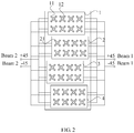
- FIG. 2 is a schematic structural diagram of an antenna array according to an embodiment of the present invention. As shown in FIG. 2 , the antenna array includes:
- the antenna array provided in this embodiment of the present invention may include a multibeam antenna array, for example, a dual-beam antenna array as shown in FIG. 2 .
- the antenna sub-arrays may be arranged in parallel.
- the antenna sub-arrays may be arranged with equal spacing.
- the antenna array as shown in FIG. 2 includes four antenna sub-arrays in the vertical direction, that is, an antenna sub-array 1, an antenna sub-array 2, an antenna sub-array 3, and an antenna sub-array 4.
- the antenna array provided in this embodiment is illustrated by taking an example in FIG. 2 that each of the antenna sub-arrays includes 2 rows x 4 columns of radiating elements. It can be understood that, in the antenna array provided in this embodiment of the present invention, the row number and/or the column number of the radiating elements included in each of the antenna sub-arrays may be different.
- the radiating elements at corresponding positions in the respective antenna sub-arrays are arranged in a staggered manner in the horizontal direction, so as to reduce energy of horizontal side lobes in an antenna array pattern and counteract the energy of the horizontal side lobes after synthesis of the pattern of each antenna sub-array.
- the radiating elements at corresponding positions in the respective antenna sub-arrays refer to the radiating elements of the same row number and the same column number in the respective antenna sub-arrays.
- a radiating element 11 in the first row and the first column in the first antenna sub-array 1 and a radiating element 21 in the first row and the first column in the second antenna sub-array 2 are two radiating elements at corresponding positions. It can be seen from FIG.
- the radiating element 21 in the first row and the first column in the second antenna sub-array 2 and the radiating element 11 in the first row and the first column in the first antenna sub-array 1 are not aligned in the vertical direction, whereas the radiating element 21 in the first row and the first column in the second antenna sub-array 2 is staggered rightward in the horizontal direction at a distance from the radiating element 11 in the first row and the first column in the first antenna sub-array 1.
- the radiating element 21 in the first row and the first column in the second antenna sub-array 2 may also be staggered leftward in the horizontal direction at a distance from the radiating element 11 in the first row and the first column in the first antenna sub-array 1.
- At least one radiating element in one antenna sub-array may be located in the vertical direction between two radiating elements in another antenna sub-array.
- the radiating element 21 in the first row and the first column in the second antenna sub-array 2 is located in the vertical direction between the radiating element 11 in the first row and the first column and the radiating element 12 in the first row and the second column in the first antenna sub-array 1.
- At least one radiating element in one antenna sub-array is located in the vertical direction in a center line of two radiating elements in another antenna sub-array.
- the radiating element 21 in the first row and the first column in the second antenna sub-array 2 is located in the vertical direction in a center line of the radiating element 11 in the first row and the first column in the first antenna sub-array 1 and the radiating element 12 in the first row and the second column.
- a vertical distance X3 between extension lines of the radiating element 21 in the first row and the first column in the second antenna sub-array 2 and the radiating element 11 in the first row and the first column in the first antenna sub-array 1 is equal to half of the spacing X1 between the radiating element 11 in the first row and the first column and the radiating element 12 in the first row and the second column in the first antenna sub-array 1.
- the energy of the horizontal side lobes after synthesis of the pattern of each antenna sub-array may be counteracted, thereby improving the ultra-wideband performance of the antenna array and increasing the communication system capacity.
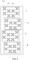
- FIG. 4 is a schematic structural diagram of an antenna array according to another embodiment of the present invention. As shown in FIG. 4 , based on the foregoing embodiment, alternatively, in at least one antenna sub-array of the antenna array, at least two adjacent radiating elements in a horizontal direction may be arranged in a staggered manner in a vertical direction.
- a radiating element 12 in the first row and the second column is staggered downward in the vertical direction at a distance from a radiating element 11 in the first row and the first column, is not staggered in the vertical direction from a radiating element 13 in the first row and the third column, and is aligned with the radiating element 13 in the first row and the third column in the horizontal direction.
- a radiating element 12 in the first row and the second column is staggered downward in the vertical direction at a distance from a radiating element 11 in the first row and the first column, and is further staggered downward in the vertical direction at a distance from a radiating element 13 in the first row and the third column.
- each of the antenna sub-arrays includes 2 rows x 4 columns of radiating elements in FIG. 4 and FIG. 5 , which is taken as an example for illustrating the antenna array provided in this embodiment. It can be understood that, in the antenna array provided in this embodiment, the row number and/or column number of the radiating elements included in each of the antenna sub-arrays may be different.
- At least one radiating element may be located in the horizontal direction between two adjacent radiating elements in the vertical direction.
- the radiating element 12 in the first row and the second column is located in the horizontal direction between the radiating element 11 in the first row and the first column and the radiating element 15 in the second row and the first column.
- At least one radiating element is located in the horizontal direction in a center line of two adjacent radiating elements in the vertical direction.
- the radiating element 12 in the first row and the second column is located in the horizontal direction in a center line of the radiating element 11 in the first row and the first column and the radiating element 15 in the second row and the first column.
- the energy of the horizontal side lobes in the antenna array pattern is reduced, the energy of vertical far side lobes after synthesis of the pattern of each antenna sub-array may be counteracted, thereby improving the ultra-wideband performance of the antenna array and increasing the communication system capacity.
- adjacent antenna sub-arrays in the vertical top-down direction may be alternately arranged in a staggered manner in different horizontal directions.
- the second antenna sub-array 2 in a first group of adjacent antenna sub-arrays in the vertical top-down direction, that is, the antenna sub-array 1 and the antenna sub-array 2, the second antenna sub-array 2 is staggered rightward in the horizontal direction from the antenna sub-array 1.
- the antenna sub-array 3 is staggered leftward in the horizontal direction from the antenna sub-array 2.
- the spacing between adjacent radiating elements in at least one antenna sub-array is equal to the spacing between adjacent radiating elements in another antenna sub-array adjacent to the foregoing antenna sub-array in the vertical direction.
- the spacing between adjacent radiating elements in the first antenna sub-array 1 is X1
- the spacing between adjacent radiating elements in the second antenna sub-array 2 is X2
- a phase difference of 45° may exist between a signal input into a radiating element in at least one antenna sub-array and a signal input into a radiating element at a corresponding position in another antenna sub-array adjacent to the foregoing antenna sub-array in the vertical direction so as to further reduce the vertical far side lobes.
- a phase difference of 45° may exist between a signal input into a radiating element in at least one antenna sub-array and a signal input into a radiating element at a corresponding position in another antenna sub-array adjacent to the foregoing antenna sub-array in the vertical direction so as to further reduce the vertical far side lobes.
- the phase of a signal input into a radiating element 35 in the second row and the first column in a third antenna sub-array 3 is +90°
- the phase of a signal input into a radiating element 45 in the second row and the first column in a fourth antenna sub-array 4 is +45°
- the phase of a signal input into a radiating element 36 in the second row and the second column in the third antenna sub-array 3 is 0°
- the phase of a signal input into the radiating element 46 in the second row and the second column in the fourth antenna sub-array 4 is -45°, and so on.
- radiating elements located in a same column may be electrically connected, and/or radiating elements located in a same row may be electrically connected so as to simplify the feeder connection of the antenna array.
- FIG. 7 shows an implementation scenario where radiating elements in a same column are electrically connected in an antenna sub-array 1, an antenna sub-array 2, an antenna sub-array 3 and an antenna sub-array 4.
- each of the antenna sub-arrays in the antenna array provided in this embodiment of the present invention, the number of radiating elements in each row may be equal, and the number of radiating elements in each column also may be equal.
- FIG. 2 to FIG. 7 show implementation scenarios where the antenna sub-array 1, the antenna sub-array 2, the antenna sub-array 3, and the antenna sub-array 4 all include 2 rows x 4 columns of radiating elements.
- FIG. 8 shows an implementation scenario where an antenna sub-array 1 to an antenna sub-array 6 all include 1 row x 4 columns of radiating elements.
- At least two antenna sub-arrays may include at least two types of antenna sub-arrays, each type of the antenna array may include m rows x n columns of radiating elements, and m and/or n in different antenna sub-arrays may be unequal, where m and n are both integers greater than one.
- antenna sub-array 9 includes two types of antenna sub-arrays, where an antenna sub-array 1 and an antenna sub-array 3 are antenna sub-arrays of a same type, which include 1 row x 4 columns of radiating elements, and an antenna sub-array 2 and an antenna sub-array 4 are antenna sub-arrays of another type, which include 2 rows x 4 columns of radiating elements.
- At least two types of antenna sub-arrays may be alternately arranged in the vertical direction. As shown in FIG. 9 , in the vertical top-down direction, the antenna sub-array 1 and the antenna sub-array 3 of the same type are alternately arranged with the antenna sub-array 2 and the antenna sub-array 4 of another type.
- the present invention further provides an antenna apparatus according to an embodiment.
- the antenna apparatus may include: at least one antenna array comprising antenna sub-arrays according to the appended claims.
- the antenna apparatus may include a beamforming network, configured to adjust the phase and the amplitude of a signal transmitted by the antenna array.
- a beamforming network configured to adjust the phase and the amplitude of a signal transmitted by the antenna array.
- two beamforming networks may be configured in the antenna apparatus.
- One beamforming network may feed one type of the antenna sub-array so as to adjust the phase and the amplitude of a signal transmitted by this type of the antenna sub-array, thereby enabling the signal transmitted by the antenna sub-array to have the preset amplitude and phase.
- the other beamforming network may feed the other type of the antenna sub-array so as to adjust the phase and the amplitude of a signal transmitted by this type of the antenna sub-array, thereby enabling the signal transmitted by the antenna sub-array to have the preset amplitude and phase.
- These two beamforming networks may be connected through devices such as a power splitter or a phase shifter.
- FIG. 10 is a schematic structural diagram of the antenna apparatus according to an embodiment.
- the antenna apparatus may include multiple antenna arrays A, among which at least one inverter array may be included.
- the feeding phase of the inverter array is opposite to the feeding phase of any other antenna array A.
- the inverter array performs inversion processing for the phase of a transmitted signal, and the inverter array and a beamforming network B together enable the signal transmitted by the inverter array to have the preset phase.
- FIG. 11 is a schematic structural diagram of a beamforming network in the antenna apparatus as shown in FIG. 10
- FIG. 12 is a schematic structural diagram of another beamforming network in the antenna apparatus as shown in FIG. 10 .
- the structures of the beamforming networks as shown in FIG. 11 and FIG. 12 are both existing structures whose principles are not described herein again.
- radiating elements at corresponding positions in the respective antenna sub-arrays are arranged in a staggered manner in a horizontal direction. This reduces the energy of horizontal side lobes in an antenna array pattern, improves the ultra-wideband performance, and increases the communication system capacity.
- the present invention further provides a base station according to an embodiment, including an antenna apparatus.
- the antenna apparatus may include: at least one antenna array comprising antenna sub-arrays according to the appended claims.
- FIG. 13 is a schematic structural diagram of the base station according to an embodiment of the present invention.
- an antenna apparatus of the base station may include: at least one antenna array A, at least one beamforming network B, and at least one phase shifter C, where
- the beamforming network B is configured to adjust the phase and the amplitude of a signal transmitted by the antenna array; and the phase shifter C is configured to adjust a downtilt angle of the antenna apparatus.
- radiating elements at corresponding positions in the respective antenna sub-arrays are arranged in a staggered manner in a horizontal direction. This reduces the energy of horizontal side lobes in an antenna array pattern, improves the ultra-wideband performance, and increases the communication system capacity.
- the communication system needs to add base stations to expand the system capacity, for example, 6-sector network construction may be used to expand the system capacity without adding any station, and it is a preferred method to adopt a multibeam antenna to expand the system capacity.
- the antenna array and the antenna apparatus provided in the embodiments of the present invention are applicable to a multibeam application scenario, and the antenna apparatus in the base station provided in the embodiment of the present invention is applicable to the multibeam application scenario.
- the pattern of the antenna array provided in the present invention as shown in FIG. 15 has lower energy in the horizontal side lobes.
Landscapes
- Engineering & Computer Science (AREA)
- Computer Networks & Wireless Communication (AREA)
- Variable-Direction Aerials And Aerial Arrays (AREA)
Description
- Embodiments of the present invention relate to the field of communications technologies, and in particular to an antenna array, an antenna apparatus, and a base station.
- With the development of mobile communications technologies, increasingly high demands are imposed on improvements of communication system capacity, optimization of pattern performance, and the like.
FIG. 1 is a schematic structural diagram of an existing antenna array, where the antenna array is comprised of five antenna sub-arrays in a vertical direction. Generally, the horizontal spacing between radiating elements in the antenna sub-array is approximately less than half of an operating wavelength, and under certain power distribution, a requirement of the antenna array for low side lobes in horizontal beams can be met. An antenna array with elements spaced at a distance of half the operating wavelentgth is shown inJP-2000236213-A - Another antenna array is shown in
JP-H11 88044-A - However, in an implementation scenario where an operating frequency band of the antenna array is a wideband, the horizontal spacing between the radiating elements in the antenna sub-array cannot meet the half-wavelength requirement for each frequency point in the wideband. As a result, the energy of the horizontal side lobes in the antenna array pattern is high, and ultra-wideband performance is poor. This affects the communication system capacity.
- Embodiments of the present invention provide an antenna array, an antenna apparatus, and a base station to reduce energy of side lobes in horizontal beams in an antenna array pattern and improve ultra-wideband performance.
- According to one aspect, an embodiment of the present invention provides an antenna array, including: at least two antenna sub-arrays, where the at least two antenna sub-arrays are arranged in a vertical direction, each of the antenna sub-arrays includes multiple radiating elements,
wherein in at least two adjacent antenna sub-arrays in the vertical direction, radiating elements at corresponding positions in the respective antenna sub-arrays are arranged in a staggered manner in a horizontal direction, and
wherein in a top-down direction, a vertical distance between extension lines of a radiating element in a first row and a first column in a second antenna sub-array and a radiating element in a first row and a first column in a first antenna sub-array is equal to half of a spacing between the radiating element in the first row and the first column in the first antenna sub-array and a radiating element in the first row and a second column in the first antenna sub-array. - According to another aspect, an embodiment of the present invention provides an antenna apparatus, including at least one antenna array, where the antenna array includes: at least two antenna sub-arrays, the at least two antenna sub-arrays are arranged in a vertical direction, and each of the antenna sub-arrays includes multiple radiating elements, and in at least two adjacent antenna sub-arrays in the vertical direction, radiating elements at corresponding positions in the respective antenna sub-arrays are arranged in a staggered manner in a horizontal direction.
- According to still another aspect, an embodiment of the present invention provides a base station, including: an antenna apparatus, where:
the antenna apparatus includes at least one antenna array; the antenna array includes at least two antenna sub-arrays, where the at least two antenna sub-arrays are arranged in a vertical direction, and each of the antenna sub-arrays includes multiple radiating elements; and in at least two adjacent antenna sub-arrays in the vertical direction, radiating elements at corresponding positions in the respective antenna sub-arrays are arranged in a staggered manner in a horizontal direction. - According to the antenna array, the antenna apparatus, and the base station provided in the embodiments of the present invention, in the antenna array, in at least two adjacent antenna sub-arrays in a vertical direction, radiating elements at corresponding positions in the respective antenna sub-arrays are arranged in a staggered manner in the horizontal direction. This reduces the energy of horizontal side lobes in an antenna array pattern, improves the ultra-wideband performance, and increases the communication system capacity.
- To describe the technical solutions according to the embodiments of the present invention or in the prior art more clearly, the accompanying drawings required for describing the embodiments or the prior art are introduced below briefly. Apparently, the accompanying drawings in the following descriptions merely show some of the embodiments of the present invention, and persons of ordinary skill in the art can obtain other drawings according to the accompanying drawings without creative efforts.
-
FIG. 1 is a schematic structural diagram of an existing antenna array; -
FIG. 2 is a schematic structural diagram of an antenna array according to an embodiment of the present invention; -
FIG. 3 is a schematic structural diagram of an antenna array according to another embodiment of the present invention; -
FIG. 4 is a schematic structural diagram of an antenna array according to still another embodiment of the present invention; -
FIG. 5 is a schematic structural diagram of an antenna array according to still another embodiment of the present invention; -
FIG. 6 is a schematic structural diagram of an antenna array according to still another embodiment of the present invention; -
FIG. 7 is a schematic structural diagram of an antenna array according to still another embodiment of the present invention; -
FIG. 8 is a schematic structural diagram of an antenna array according to still another embodiment of the present invention; -
FIG. 9 is a schematic structural diagram of an antenna array according to still another embodiment of the present invention; -
FIG. 10 is a schematic structural diagram of an antenna apparatus according to an embodiment of the present invention; -
FIG. 11 is a schematic structural diagram of a beamforming network in the antenna apparatus as shown inFIG. 10 ; -
FIG. 12 is a schematic structural diagram of another beamforming network in the antenna apparatus as shown inFIG. 10 ; -
FIG. 13 is a schematic structural diagram of a base station according to an embodiment of the present invention; -
FIG. 14 is a horizontal pattern of the existing antenna array; and -
FIG. 15 is a horizontal pattern of the antenna array according to an embodiment of the present invention. - The technical solutions of the present invention will be clearly and completely described in the following with reference to the accompanying drawings. It is obvious that the embodiments to be described are only a part rather than all of the embodiments of the present invention. All other embodiments obtained by persons of ordinary skill in the art based on the embodiments of the present invention without creative efforts shall fall within the protection scope of the present invention.
-
FIG. 2 is a schematic structural diagram of an antenna array according to an embodiment of the present invention. As shown inFIG. 2 , the antenna array includes: - at least two antenna sub-arrays, where the at least two antenna sub-arrays are arranged in a vertical direction, each of the antenna sub-arrays includes multiple radiating elements, and
- in at least two adjacent antenna sub-arrays in the vertical direction, radiating elements at corresponding positions in the respective antenna sub-arrays are arranged in a staggered manner in a horizontal direction.
- The antenna array provided in this embodiment of the present invention may include a multibeam antenna array, for example, a dual-beam antenna array as shown in
FIG. 2 . For example, the antenna sub-arrays may be arranged in parallel. In an implementation scenario where three or more antenna sub-arrays in the antenna array are arranged in the vertical direction, the antenna sub-arrays may be arranged with equal spacing. - The antenna array as shown in
FIG. 2 includes four antenna sub-arrays in the vertical direction, that is, anantenna sub-array 1, anantenna sub-array 2, anantenna sub-array 3, and anantenna sub-array 4. The antenna array provided in this embodiment is illustrated by taking an example inFIG. 2 that each of the antenna sub-arrays includes 2 rows x 4 columns of radiating elements. It can be understood that, in the antenna array provided in this embodiment of the present invention, the row number and/or the column number of the radiating elements included in each of the antenna sub-arrays may be different. - In at least two adjacent antenna sub-arrays in the vertical direction in the antenna array provided in this embodiment of the present invention, the radiating elements at corresponding positions in the respective antenna sub-arrays are arranged in a staggered manner in the horizontal direction, so as to reduce energy of horizontal side lobes in an antenna array pattern and counteract the energy of the horizontal side lobes after synthesis of the pattern of each antenna sub-array. The radiating elements at corresponding positions in the respective antenna sub-arrays refer to the radiating elements of the same row number and the same column number in the respective antenna sub-arrays.
- For example, in the antenna array as shown in
FIG. 2 , in a top-down direction, aradiating element 11 in the first row and the first column in thefirst antenna sub-array 1 and aradiating element 21 in the first row and the first column in thesecond antenna sub-array 2 are two radiating elements at corresponding positions. It can be seen fromFIG. 2 that, theradiating element 21 in the first row and the first column in thesecond antenna sub-array 2 and theradiating element 11 in the first row and the first column in thefirst antenna sub-array 1 are not aligned in the vertical direction, whereas theradiating element 21 in the first row and the first column in thesecond antenna sub-array 2 is staggered rightward in the horizontal direction at a distance from theradiating element 11 in the first row and the first column in thefirst antenna sub-array 1. - It can be understood that, as another feasible embodiment, the
radiating element 21 in the first row and the first column in thesecond antenna sub-array 2 may also be staggered leftward in the horizontal direction at a distance from theradiating element 11 in the first row and the first column in thefirst antenna sub-array 1. - Alternatively, in the at least two adjacent antenna sub-arrays in the vertical direction, at least one radiating element in one antenna sub-array may be located in the vertical direction between two radiating elements in another antenna sub-array. For example, in the antenna array as shown in
FIG. 2 , in the top-down direction, theradiating element 21 in the first row and the first column in thesecond antenna sub-array 2 is located in the vertical direction between theradiating element 11 in the first row and the first column and theradiating element 12 in the first row and the second column in thefirst antenna sub-array 1. - In the at least two adjacent antenna sub-arrays in the vertical direction, at least one radiating element in one antenna sub-array is located in the vertical direction in a center line of two radiating elements in another antenna sub-array. For example, in the antenna array as shown in
FIG. 2 , in the top-down direction, theradiating element 21 in the first row and the first column in thesecond antenna sub-array 2 is located in the vertical direction in a center line of theradiating element 11 in the first row and the first column in thefirst antenna sub-array 1 and theradiating element 12 in the first row and the second column. As shown inFIG. 3 , in the top-down direction, a vertical distance X3 between extension lines of theradiating element 21 in the first row and the first column in thesecond antenna sub-array 2 and theradiating element 11 in the first row and the first column in thefirst antenna sub-array 1 is equal to half of the spacing X1 between theradiating element 11 in the first row and the first column and theradiating element 12 in the first row and the second column in thefirst antenna sub-array 1. - Through the foregoing configuration, the energy of the horizontal side lobes after synthesis of the pattern of each antenna sub-array may be counteracted, thereby improving the ultra-wideband performance of the antenna array and increasing the communication system capacity.
-
FIG. 4 is a schematic structural diagram of an antenna array according to another embodiment of the present invention. As shown inFIG. 4 , based on the foregoing embodiment, alternatively, in at least one antenna sub-array of the antenna array, at least two adjacent radiating elements in a horizontal direction may be arranged in a staggered manner in a vertical direction. - In the antenna array as shown in
FIG. 4 , in afirst antenna sub-array 1 in a top-down direction, a radiatingelement 12 in the first row and the second column is staggered downward in the vertical direction at a distance from a radiatingelement 11 in the first row and the first column, is not staggered in the vertical direction from a radiatingelement 13 in the first row and the third column, and is aligned with the radiatingelement 13 in the first row and the third column in the horizontal direction. - In an antenna array as shown in
FIG. 5 , in afirst antenna sub-array 1 in the top-down direction, a radiatingelement 12 in the first row and the second column is staggered downward in the vertical direction at a distance from a radiatingelement 11 in the first row and the first column, and is further staggered downward in the vertical direction at a distance from a radiatingelement 13 in the first row and the third column. - It should be noted that each of the antenna sub-arrays includes 2 rows x 4 columns of radiating elements in
FIG. 4 andFIG. 5 , which is taken as an example for illustrating the antenna array provided in this embodiment. It can be understood that, in the antenna array provided in this embodiment, the row number and/or column number of the radiating elements included in each of the antenna sub-arrays may be different. - Alternatively, in at least one antenna sub-array, at least one radiating element may be located in the horizontal direction between two adjacent radiating elements in the vertical direction. For example, in the antenna array as shown in
FIG. 5 , in thefirst antenna sub-array 1 in the top-down direction, the radiatingelement 12 in the first row and the second column is located in the horizontal direction between the radiatingelement 11 in the first row and the first column and the radiatingelement 15 in the second row and the first column. - In at least one antenna sub-array, at least one radiating element is located in the horizontal direction in a center line of two adjacent radiating elements in the vertical direction. For example, in the antenna array as shown in
FIG. 5 , in thefirst antenna sub-array 1 in the top-down direction, the radiatingelement 12 in the first row and the second column is located in the horizontal direction in a center line of the radiatingelement 11 in the first row and the first column and the radiatingelement 15 in the second row and the first column. - Through the foregoing configuration, on the basis that the energy of the horizontal side lobes in the antenna array pattern is reduced, the energy of vertical far side lobes after synthesis of the pattern of each antenna sub-array may be counteracted, thereby improving the ultra-wideband performance of the antenna array and increasing the communication system capacity.
- Based on the foregoing embodiment, alternatively, adjacent antenna sub-arrays in the vertical top-down direction may be alternately arranged in a staggered manner in different horizontal directions. For example, in the antenna arrays as shown in
FIG. 2 to FIG. 5 , in a first group of adjacent antenna sub-arrays in the vertical top-down direction, that is, theantenna sub-array 1 and theantenna sub-array 2, thesecond antenna sub-array 2 is staggered rightward in the horizontal direction from theantenna sub-array 1. In a second group of adjacent antenna sub-arrays in the vertical top-down direction, that is, theantenna sub-array 2 and theantenna sub-array 3, theantenna sub-array 3 is staggered leftward in the horizontal direction from theantenna sub-array 2. - Based on the foregoing embodiment, alternatively, the spacing between adjacent radiating elements in at least one antenna sub-array is equal to the spacing between adjacent radiating elements in another antenna sub-array adjacent to the foregoing antenna sub-array in the vertical direction. For example, in the antenna array as shown in
FIG. 3 , in the vertical top-down direction, assuming that the spacing between adjacent radiating elements in thefirst antenna sub-array 1 is X1 and the spacing between adjacent radiating elements in thesecond antenna sub-array 2 is X2, it may be set that X1 = X2. - In the antenna array pattern, alternatively, a phase difference of 45° may exist between a signal input into a radiating element in at least one antenna sub-array and a signal input into a radiating element at a corresponding position in another antenna sub-array adjacent to the foregoing antenna sub-array in the vertical direction so as to further reduce the vertical far side lobes. As shown in
FIG. 6 , in the vertical top-down direction, the phase of a signal input into a radiatingelement 35 in the second row and the first column in athird antenna sub-array 3 is +90°, and the phase of a signal input into a radiatingelement 45 in the second row and the first column in afourth antenna sub-array 4 is +45°; the phase of a signal input into a radiatingelement 36 in the second row and the second column in thethird antenna sub-array 3 is 0°, and the phase of a signal input into the radiatingelement 46 in the second row and the second column in thefourth antenna sub-array 4 is -45°, and so on. - Alternatively, in at least one antenna sub-array, radiating elements located in a same column may be electrically connected, and/or radiating elements located in a same row may be electrically connected so as to simplify the feeder connection of the antenna array.
FIG. 7 shows an implementation scenario where radiating elements in a same column are electrically connected in anantenna sub-array 1, anantenna sub-array 2, anantenna sub-array 3 and anantenna sub-array 4. - As a feasible implementation manner, in each of the antenna sub-arrays in the antenna array provided in this embodiment of the present invention, the number of radiating elements in each row may be equal, and the number of radiating elements in each column also may be equal.
FIG. 2 to FIG. 7 show implementation scenarios where theantenna sub-array 1, theantenna sub-array 2, theantenna sub-array 3, and theantenna sub-array 4 all include 2 rows x 4 columns of radiating elements. For another example,FIG. 8 shows an implementation scenario where anantenna sub-array 1 to anantenna sub-array 6 all include 1 row x 4 columns of radiating elements. - As another feasible implementation manner, in the antenna array provided in this embodiment of the present invention, at least two antenna sub-arrays may include at least two types of antenna sub-arrays, each type of the antenna array may include m rows x n columns of radiating elements, and m and/or n in different antenna sub-arrays may be unequal, where m and n are both integers greater than one. For example, an antenna array as shown in
FIG. 9 includes two types of antenna sub-arrays, where anantenna sub-array 1 and anantenna sub-array 3 are antenna sub-arrays of a same type, which include 1 row x 4 columns of radiating elements, and anantenna sub-array 2 and anantenna sub-array 4 are antenna sub-arrays of another type, which include 2 rows x 4 columns of radiating elements. - Alternatively, at least two types of antenna sub-arrays may be alternately arranged in the vertical direction. As shown in
FIG. 9 , in the vertical top-down direction, theantenna sub-array 1 and theantenna sub-array 3 of the same type are alternately arranged with theantenna sub-array 2 and theantenna sub-array 4 of another type. - The present invention further provides an antenna apparatus according to an embodiment. The antenna apparatus may include: at least one antenna array comprising antenna sub-arrays according to the appended claims.
- The antenna apparatus may include a beamforming network, configured to adjust the phase and the amplitude of a signal transmitted by the antenna array. For example, in an implementation scenario where the antenna array includes two types of antenna sub-arrays, two beamforming networks may be configured in the antenna apparatus. One beamforming network may feed one type of the antenna sub-array so as to adjust the phase and the amplitude of a signal transmitted by this type of the antenna sub-array, thereby enabling the signal transmitted by the antenna sub-array to have the preset amplitude and phase. In addition, the other beamforming network may feed the other type of the antenna sub-array so as to adjust the phase and the amplitude of a signal transmitted by this type of the antenna sub-array, thereby enabling the signal transmitted by the antenna sub-array to have the preset amplitude and phase. These two beamforming networks may be connected through devices such as a power splitter or a phase shifter. For a specific structure and a function of the antenna array, reference may be made to the embodiment of the antenna array provided in the present invention. Therefore, no further details are provided herein.
-
FIG. 10 is a schematic structural diagram of the antenna apparatus according to an embodiment. As shown inFIG. 10 , the antenna apparatus may include multiple antenna arrays A, among which at least one inverter array may be included. The feeding phase of the inverter array is opposite to the feeding phase of any other antenna array A. The inverter array performs inversion processing for the phase of a transmitted signal, and the inverter array and a beamforming network B together enable the signal transmitted by the inverter array to have the preset phase.FIG. 11 is a schematic structural diagram of a beamforming network in the antenna apparatus as shown inFIG. 10 , andFIG. 12 is a schematic structural diagram of another beamforming network in the antenna apparatus as shown inFIG. 10 . The structures of the beamforming networks as shown inFIG. 11 and FIG. 12 are both existing structures whose principles are not described herein again. - According to the antenna apparatus provided in this embodiment of the present invention, in at least two adjacent antenna sub-arrays in a vertical direction in an antenna array, radiating elements at corresponding positions in the respective antenna sub-arrays are arranged in a staggered manner in a horizontal direction. This reduces the energy of horizontal side lobes in an antenna array pattern, improves the ultra-wideband performance, and increases the communication system capacity.
- The present invention further provides a base station according to an embodiment, including an antenna apparatus.
- The antenna apparatus may include: at least one antenna array comprising antenna sub-arrays according to the appended claims.
-
FIG. 13 is a schematic structural diagram of the base station according to an embodiment of the present invention. As shown inFIG. 13 , an antenna apparatus of the base station may include: at least one antenna array A, at least one beamforming network B, and at least one phase shifter C, where - the beamforming network B is configured to adjust the phase and the amplitude of a signal transmitted by the antenna array; and
the phase shifter C is configured to adjust a downtilt angle of the antenna apparatus. - According to the base station provided in this embodiment of the present invention, in at least two adjacent antenna sub-arrays in a vertical direction in an antenna array, radiating elements at corresponding positions in the respective antenna sub-arrays are arranged in a staggered manner in a horizontal direction. This reduces the energy of horizontal side lobes in an antenna array pattern, improves the ultra-wideband performance, and increases the communication system capacity.
- With the increasing growth of the number of users, the communication system needs to add base stations to expand the system capacity, for example, 6-sector network construction may be used to expand the system capacity without adding any station, and it is a preferred method to adopt a multibeam antenna to expand the system capacity. The antenna array and the antenna apparatus provided in the embodiments of the present invention are applicable to a multibeam application scenario, and the antenna apparatus in the base station provided in the embodiment of the present invention is applicable to the multibeam application scenario. Compared with the pattern of the existing multibeam antenna array as shown in
FIG. 14 , the pattern of the antenna array provided in the present invention as shown inFIG. 15 has lower energy in the horizontal side lobes.
Claims (12)
- An antenna array, comprising: at least two antenna sub-arrays (1), wherein the at least two antenna sub-arrays (1) are arranged in a vertical direction, each of the antenna sub-arrays (1) comprises multiple radiating elements; and
wherein in at least two adjacent antenna sub-arrays (1) in the vertical direction, radiating elements at corresponding positions in the respective antenna sub-arrays (1) are arranged in a staggered manner in a horizontal direction;
characterized in that in a top-down direction, a vertical distance (X3) between extension lines of a radiating element (21) in a first row and a first column in a second antenna sub-array (2) and a radiating element (11) in a first row and a first column in a first antenna sub-array (1) is equal to half of a spacing (X1) between the radiating element (11) in the first row and the first column in the first antenna sub-array (1) and a radiating element (12) in the first row and a second column in the first antenna sub-array (1). - The antenna array according to claim 1, wherein in the at least two adjacent antenna sub-arrays (1) in the vertical direction, at least one radiating element in one antenna sub-array is located in the vertical direction between two radiating elements in another antenna sub-array.
- The antenna array according to claim 2, wherein in the at least two adjacent antenna sub-arrays (1) in the vertical direction, at least one radiating element in one antenna sub-array is located in the vertical direction in a center line of two radiating elements in another antenna sub-array.
- The antenna array according to any one of claims 1 to 3, wherein in at least one antenna sub-array, at least two adjacent radiating elements in the horizontal direction are arranged in a staggered manner in the vertical direction.
- The antenna array according to claim 4, wherein in at least one antenna sub-array, at least one radiating element is located in the horizontal direction between two adjacent radiating elements in the vertical direction.
- The antenna array according to claim 5, wherein in at least one antenna sub-array, at least one radiating element is located in the horizontal direction in a center line of two adjacent radiating elements in the vertical direction.
- The antenna array according to any one of claims 1 to 6, wherein adjacent antenna sub-arrays (1) in a vertical top-down direction are alternately arranged in a staggered manner in different horizontal directions.
- The antenna array according to any one of claims 1 to 7, wherein the spacing between adjacent radiating elements in at least one antenna sub-array is equal to the spacing between adjacent radiating elements in another antenna sub-array adjacent to the foregoing antenna sub-array in the vertical direction.
- The antenna array according to any one of claims 1 to 8, wherein in each of the antenna sub-arrays (1), the number of radiating elements in each row is equal, and the number of radiating elements in each column is equal.
- The antenna array according to any one of claims 1 to 8, wherein at least two antenna sub-arrays (1) comprise at least two types of antenna sub-arrays (1), each type of the antenna array comprises m rows x n columns of radiating elements, and m and/or n in different antenna sub-arrays (1) are unequal, wherein m and n are both integers greater than one.
- An antenna apparatus, comprising: at least one antenna array according to any one of claims 1 to 10.
- A base station, comprising: the antenna apparatus according to claim 11.
Applications Claiming Priority (1)
| Application Number | Priority Date | Filing Date | Title |
|---|---|---|---|
| PCT/CN2012/076278 WO2012126439A2 (en) | 2012-05-30 | 2012-05-30 | Antenna array, antenna device and base station |
Publications (3)
| Publication Number | Publication Date |
|---|---|
| EP2846400A2 EP2846400A2 (en) | 2015-03-11 |
| EP2846400A4 EP2846400A4 (en) | 2015-04-22 |
| EP2846400B1 true EP2846400B1 (en) | 2019-10-09 |
Family
ID=46879814
Family Applications (1)
| Application Number | Title | Priority Date | Filing Date |
|---|---|---|---|
| EP12760991.5A Active EP2846400B1 (en) | 2012-05-30 | 2012-05-30 | Antenna array, antenna device and base station |
Country Status (5)
| Country | Link |
|---|---|
| US (1) | US10181657B2 (en) |
| EP (1) | EP2846400B1 (en) |
| JP (1) | JP5969698B2 (en) |
| CN (1) | CN102859789B (en) |
| WO (1) | WO2012126439A2 (en) |
Families Citing this family (30)
| Publication number | Priority date | Publication date | Assignee | Title |
|---|---|---|---|---|
| PL2359438T3 (en) * | 2008-11-20 | 2019-12-31 | Commscope Technologies Llc | Dual-beam sector antenna and array |
| JP6039597B2 (en) * | 2014-02-25 | 2016-12-07 | 日本電信電話株式会社 | Antenna, base station apparatus, and antenna element arrangement method |
| JP6409676B2 (en) * | 2014-06-03 | 2018-10-24 | 三菱電機株式会社 | Array antenna and antenna for satellite communication |
| US10263331B2 (en) * | 2014-10-06 | 2019-04-16 | Kymeta Corporation | Device, system and method to mitigate side lobes with an antenna array |
| JP6396244B2 (en) | 2015-03-25 | 2018-09-26 | パナソニック株式会社 | Radar equipment |
| CN105356062B (en) * | 2015-10-23 | 2021-06-18 | 广东博纬通信科技有限公司 | Broadband array antenna |
| JP6555358B2 (en) * | 2015-11-27 | 2019-08-07 | 日立金属株式会社 | Antenna device |
| WO2018094660A1 (en) * | 2016-11-24 | 2018-05-31 | 深圳市大疆创新科技有限公司 | Antenna assembly and unmanned aerial vehicle |
| US20180198204A1 (en) * | 2016-12-13 | 2018-07-12 | Skyworks Solutions, Inc. | Apparatus and methods for dynamic management of antenna arrays |
| US10381811B2 (en) * | 2017-03-29 | 2019-08-13 | Hubbell Incorporated | Utility conduit system |
| WO2018176361A1 (en) * | 2017-03-31 | 2018-10-04 | 华为技术有限公司 | Antenna downtilt adjusting apparatus and communications device |
| CN111052509B (en) * | 2017-08-30 | 2022-03-29 | 株式会社村田制作所 | Antenna module |
| CN107959125B (en) * | 2017-11-17 | 2020-10-20 | 深圳市盛路物联通讯技术有限公司 | Array antenna and wireless communication device |
| CN110071373B (en) * | 2018-03-12 | 2023-03-14 | 京信通信技术(广州)有限公司 | Multi-system integrated antenna |
| US10561029B1 (en) * | 2019-04-10 | 2020-02-11 | Innolux Corporation | Electronic device |
| US11181614B2 (en) * | 2019-06-06 | 2021-11-23 | GM Global Technology Operations LLC | Antenna array tilt and processing to eliminate false detections in a radar system |
| CN121939119A (en) * | 2020-05-09 | 2026-04-28 | 户外无线网络有限公司 | Dual-beam antenna array |
| CN111430938B (en) * | 2020-05-11 | 2025-06-24 | 摩比天线技术(深圳)有限公司 | MIMO antenna array and communication equipment |
| CN111864406A (en) * | 2020-07-29 | 2020-10-30 | 江苏泰科微通讯科技有限公司 | Miniaturized four-low-frequency multi-port base station antenna |
| US11418975B2 (en) * | 2020-10-14 | 2022-08-16 | Commscope Technologies Llc | Base station antennas with sector splitting in the elevation plan based on frequency band |
| EP4285443B1 (en) | 2021-01-28 | 2025-12-17 | Telefonaktiebolaget LM Ericsson (publ) | Antenna system, rf communication device, and method of operating the same |
| CN113013583B (en) * | 2021-01-29 | 2023-08-18 | 中国电子科技集团公司第三十八研究所 | Millimeter wave radar packaging module |
| JP7609663B2 (en) | 2021-03-10 | 2025-01-07 | 電気興業株式会社 | Array Antenna |
| US12080948B2 (en) | 2021-04-21 | 2024-09-03 | Skyworks Solutions, Inc. | Staggered rows of antennas for dual frequency operation |
| CN117480685A (en) * | 2021-06-15 | 2024-01-30 | 瑞典爱立信有限公司 | Advanced antenna system with reduced sidelobes |
| CN116404399A (en) * | 2021-12-27 | 2023-07-07 | 普罗斯通信技术(苏州)有限公司 | Radiating array group and narrow beam antenna |
| CN114447585B (en) * | 2022-01-29 | 2024-03-19 | 京东方科技集团股份有限公司 | Multi-beam antenna, preparation method and communication device thereof |
| EP4507124A4 (en) | 2022-05-04 | 2025-07-23 | Samsung Electronics Co Ltd | ELECTRONIC DEVICE WITH ANTENNA |
| WO2024183018A1 (en) * | 2023-03-08 | 2024-09-12 | 深圳市华屹医疗科技有限公司 | Antenna array and transceiving antenna array system |
| CN120073257A (en) * | 2023-11-28 | 2025-05-30 | 深圳富泰宏精密工业有限公司 | Multiplexer and array antenna module |
Family Cites Families (20)
| Publication number | Priority date | Publication date | Assignee | Title |
|---|---|---|---|---|
| US4423421A (en) * | 1979-11-26 | 1983-12-27 | Raytheon Company | Slot array antenna with amplitude taper across a small circular aperture |
| SE449540B (en) * | 1985-10-31 | 1987-05-04 | Ericsson Telefon Ab L M | LETTER MANAGEMENT FOR AN ELECTRICALLY CONTROLLED RADAR ANTENNA |
| JP3415001B2 (en) * | 1997-09-10 | 2003-06-09 | 三菱電機株式会社 | Array antenna |
| JP3812203B2 (en) * | 1999-02-17 | 2006-08-23 | 三菱電機株式会社 | Waveguide slot array antenna |
| SE518207C2 (en) * | 1999-09-10 | 2002-09-10 | Ericsson Telefon Ab L M | Large group antenna |
| JP4021150B2 (en) * | 2001-01-29 | 2007-12-12 | 沖電気工業株式会社 | Slot array antenna |
| CN1507673A (en) * | 2001-04-16 | 2004-06-23 | �����ɷ� | Dual-band dual-polarized antenna array |
| JP2005303801A (en) * | 2004-04-14 | 2005-10-27 | Toyota Central Res & Dev Lab Inc | Antenna device |
| CN100369324C (en) * | 2005-05-30 | 2008-02-13 | 东南大学 | Substrate Integrated Waveguide Dual-band Broadband Slot Array Antenna Unit |
| CN100530818C (en) * | 2005-06-08 | 2009-08-19 | 东南大学 | Dielectric substrate integrated waveguide slot array antenna |
| JP4602276B2 (en) * | 2006-03-23 | 2010-12-22 | 三菱電機株式会社 | Waveguide slot array antenna device |
| EP1965462B1 (en) * | 2007-03-02 | 2010-09-01 | Saab Ab | Hull integrated antenna |
| WO2009052218A1 (en) * | 2007-10-16 | 2009-04-23 | Powerwave Technologies, Inc. | Dual beam sector antenna array with low loss beam forming network |
| CN201134510Y (en) * | 2007-10-31 | 2008-10-15 | 京信通信系统(中国)有限公司 | Miniaturized Smart Antenna System |
| JP2009159225A (en) * | 2007-12-26 | 2009-07-16 | Samsung Electronics Co Ltd | Antenna device |
| PL2359438T3 (en) * | 2008-11-20 | 2019-12-31 | Commscope Technologies Llc | Dual-beam sector antenna and array |
| CN201336371Y (en) * | 2008-12-22 | 2009-10-28 | 东莞市晖速天线技术有限公司 | Staggered-arrangement flat plate directional intelligent antenna array |
| CN201397879Y (en) * | 2009-01-09 | 2010-02-03 | 东莞市晖速天线技术有限公司 | Device used for adjusting electrical downtilt of mobile communication antenna |
| CN201392888Y (en) * | 2009-04-10 | 2010-01-27 | 北京华盛天基通信技术有限公司 | Intelligent dual-polarized antenna |
| JP5620757B2 (en) * | 2010-09-01 | 2014-11-05 | 株式会社豊田中央研究所 | Radar equipment |
-
2012
- 2012-05-30 WO PCT/CN2012/076278 patent/WO2012126439A2/en not_active Ceased
- 2012-05-30 EP EP12760991.5A patent/EP2846400B1/en active Active
- 2012-05-30 CN CN201280000882.0A patent/CN102859789B/en active Active
- 2012-05-30 JP JP2015514315A patent/JP5969698B2/en active Active
-
2014
- 2014-11-26 US US14/554,765 patent/US10181657B2/en active Active
Non-Patent Citations (1)
| Title |
|---|
| None * |
Also Published As
| Publication number | Publication date |
|---|---|
| WO2012126439A2 (en) | 2012-09-27 |
| CN102859789A (en) | 2013-01-02 |
| US20150084832A1 (en) | 2015-03-26 |
| EP2846400A4 (en) | 2015-04-22 |
| EP2846400A2 (en) | 2015-03-11 |
| JP2015521441A (en) | 2015-07-27 |
| US10181657B2 (en) | 2019-01-15 |
| WO2012126439A3 (en) | 2013-05-02 |
| JP5969698B2 (en) | 2016-08-17 |
| CN102859789B (en) | 2016-04-13 |
Similar Documents
| Publication | Publication Date | Title |
|---|---|---|
| US10181657B2 (en) | Antenna array, antenna apparatus, and base station | |
| EP2685557B1 (en) | Antenna and base station | |
| Black | Holographic beam forming and MIMO | |
| CN107196684B (en) | Antenna system, signal processing system and signal processing method | |
| EP3379648B1 (en) | Planar array antenna and communication device | |
| KR101858042B1 (en) | Multi-beam antenna system and phase adjustment method thereof, and dual-polarization antenna system | |
| US9515377B2 (en) | Antenna apparatus, antenna device and signal transmitting apparatus | |
| EP3120416B1 (en) | Compact antenna array using virtual rotation of radiating vectors | |
| US9438278B2 (en) | Multi-array antenna | |
| US9397740B2 (en) | Modular antenna array with RF and baseband beamforming | |
| CN105322987B (en) | Wireless network device and wireless network control method | |
| CN102544759B (en) | Unipolar sixteen-beam antenna for mobile communication base station | |
| US10637587B2 (en) | Communications apparatus and wireless communications device | |
| CN105356062B (en) | Broadband array antenna | |
| CN106252901A (en) | Wideband three beam array antenna | |
| WO2015078404A1 (en) | Antenna and method for transmitting and receiving wireless signal | |
| CN106252903B (en) | Dual-frequency two-beam antenna array and dual-frequency two-beam antenna | |
| EP3472942B1 (en) | Flexible analog architecture for sectorization | |
| CN205004448U (en) | Wide band array antenna | |
| CN106159465A (en) | Wideband five beam array antenna | |
| CN103765940A (en) | Sector configuration method and device, system | |
| CN104639217A (en) | Antenna system, antenna and base station | |
| CN110994203B (en) | Broadband mixed multi-beam array antenna | |
| US20180248263A1 (en) | Antenna structure for beamforming | |
| CN213184604U (en) | Antenna system |
Legal Events
| Date | Code | Title | Description |
|---|---|---|---|
| PUAI | Public reference made under article 153(3) epc to a published international application that has entered the european phase |
Free format text: ORIGINAL CODE: 0009012 |
|
| 17P | Request for examination filed |
Effective date: 20141203 |
|
| AK | Designated contracting states |
Kind code of ref document: A2 Designated state(s): AL AT BE BG CH CY CZ DE DK EE ES FI FR GB GR HR HU IE IS IT LI LT LU LV MC MK MT NL NO PL PT RO RS SE SI SK SM TR |
|
| AX | Request for extension of the european patent |
Extension state: BA ME |
|
| A4 | Supplementary search report drawn up and despatched |
Effective date: 20150323 |
|
| RIC1 | Information provided on ipc code assigned before grant |
Ipc: H01Q 3/40 20060101ALN20150317BHEP Ipc: H01Q 21/06 20060101AFI20150317BHEP |
|
| DAX | Request for extension of the european patent (deleted) | ||
| GRAP | Despatch of communication of intention to grant a patent |
Free format text: ORIGINAL CODE: EPIDOSNIGR1 |
|
| STAA | Information on the status of an ep patent application or granted ep patent |
Free format text: STATUS: GRANT OF PATENT IS INTENDED |
|
| RIC1 | Information provided on ipc code assigned before grant |
Ipc: H01Q 3/40 20060101ALN20181107BHEP Ipc: H01Q 21/06 20060101AFI20181107BHEP |
|
| RIC1 | Information provided on ipc code assigned before grant |
Ipc: H01Q 3/40 20060101ALN20181115BHEP Ipc: H01Q 21/06 20060101AFI20181115BHEP |
|
| INTG | Intention to grant announced |
Effective date: 20181211 |
|
| GRAS | Grant fee paid |
Free format text: ORIGINAL CODE: EPIDOSNIGR3 |
|
| GRAJ | Information related to disapproval of communication of intention to grant by the applicant or resumption of examination proceedings by the epo deleted |
Free format text: ORIGINAL CODE: EPIDOSDIGR1 |
|
| GRAL | Information related to payment of fee for publishing/printing deleted |
Free format text: ORIGINAL CODE: EPIDOSDIGR3 |
|
| STAA | Information on the status of an ep patent application or granted ep patent |
Free format text: STATUS: REQUEST FOR EXAMINATION WAS MADE |
|
| INTC | Intention to grant announced (deleted) | ||
| RIC1 | Information provided on ipc code assigned before grant |
Ipc: H01Q 3/40 20060101ALN20190425BHEP Ipc: H01Q 21/06 20060101AFI20190425BHEP |
|
| GRAP | Despatch of communication of intention to grant a patent |
Free format text: ORIGINAL CODE: EPIDOSNIGR1 |
|
| STAA | Information on the status of an ep patent application or granted ep patent |
Free format text: STATUS: GRANT OF PATENT IS INTENDED |
|
| GRAJ | Information related to disapproval of communication of intention to grant by the applicant or resumption of examination proceedings by the epo deleted |
Free format text: ORIGINAL CODE: EPIDOSDIGR1 |
|
| GRAL | Information related to payment of fee for publishing/printing deleted |
Free format text: ORIGINAL CODE: EPIDOSDIGR3 |
|
| STAA | Information on the status of an ep patent application or granted ep patent |
Free format text: STATUS: REQUEST FOR EXAMINATION WAS MADE |
|
| INTG | Intention to grant announced |
Effective date: 20190604 |
|
| REG | Reference to a national code |
Ref country code: DE Ref legal event code: R079 Ref document number: 602012064733 Country of ref document: DE Free format text: PREVIOUS MAIN CLASS: H01Q0003000000 Ipc: H01Q0021060000 |
|
| INTC | Intention to grant announced (deleted) | ||
| GRAP | Despatch of communication of intention to grant a patent |
Free format text: ORIGINAL CODE: EPIDOSNIGR1 |
|
| STAA | Information on the status of an ep patent application or granted ep patent |
Free format text: STATUS: GRANT OF PATENT IS INTENDED |
|
| RIC1 | Information provided on ipc code assigned before grant |
Ipc: H01Q 21/06 20060101AFI20190708BHEP Ipc: H01Q 3/40 20060101ALN20190708BHEP |
|
| INTG | Intention to grant announced |
Effective date: 20190731 |
|
| GRAA | (expected) grant |
Free format text: ORIGINAL CODE: 0009210 |
|
| STAA | Information on the status of an ep patent application or granted ep patent |
Free format text: STATUS: THE PATENT HAS BEEN GRANTED |
|
| AK | Designated contracting states |
Kind code of ref document: B1 Designated state(s): AL AT BE BG CH CY CZ DE DK EE ES FI FR GB GR HR HU IE IS IT LI LT LU LV MC MK MT NL NO PL PT RO RS SE SI SK SM TR |
|
| REG | Reference to a national code |
Ref country code: GB Ref legal event code: FG4D |
|
| REG | Reference to a national code |
Ref country code: CH Ref legal event code: EP |
|
| REG | Reference to a national code |
Ref country code: DE Ref legal event code: R096 Ref document number: 602012064733 Country of ref document: DE |
|
| REG | Reference to a national code |
Ref country code: IE Ref legal event code: FG4D |
|
| REG | Reference to a national code |
Ref country code: AT Ref legal event code: REF Ref document number: 1189900 Country of ref document: AT Kind code of ref document: T Effective date: 20191115 |
|
| REG | Reference to a national code |
Ref country code: NL Ref legal event code: FP |
|
| REG | Reference to a national code |
Ref country code: LT Ref legal event code: MG4D |
|
| REG | Reference to a national code |
Ref country code: AT Ref legal event code: MK05 Ref document number: 1189900 Country of ref document: AT Kind code of ref document: T Effective date: 20191009 |
|
| PG25 | Lapsed in a contracting state [announced via postgrant information from national office to epo] |
Ref country code: BG Free format text: LAPSE BECAUSE OF FAILURE TO SUBMIT A TRANSLATION OF THE DESCRIPTION OR TO PAY THE FEE WITHIN THE PRESCRIBED TIME-LIMIT Effective date: 20200109 Ref country code: FI Free format text: LAPSE BECAUSE OF FAILURE TO SUBMIT A TRANSLATION OF THE DESCRIPTION OR TO PAY THE FEE WITHIN THE PRESCRIBED TIME-LIMIT Effective date: 20191009 Ref country code: NO Free format text: LAPSE BECAUSE OF FAILURE TO SUBMIT A TRANSLATION OF THE DESCRIPTION OR TO PAY THE FEE WITHIN THE PRESCRIBED TIME-LIMIT Effective date: 20200109 Ref country code: AT Free format text: LAPSE BECAUSE OF FAILURE TO SUBMIT A TRANSLATION OF THE DESCRIPTION OR TO PAY THE FEE WITHIN THE PRESCRIBED TIME-LIMIT Effective date: 20191009 Ref country code: GR Free format text: LAPSE BECAUSE OF FAILURE TO SUBMIT A TRANSLATION OF THE DESCRIPTION OR TO PAY THE FEE WITHIN THE PRESCRIBED TIME-LIMIT Effective date: 20200110 Ref country code: PT Free format text: LAPSE BECAUSE OF FAILURE TO SUBMIT A TRANSLATION OF THE DESCRIPTION OR TO PAY THE FEE WITHIN THE PRESCRIBED TIME-LIMIT Effective date: 20200210 Ref country code: ES Free format text: LAPSE BECAUSE OF FAILURE TO SUBMIT A TRANSLATION OF THE DESCRIPTION OR TO PAY THE FEE WITHIN THE PRESCRIBED TIME-LIMIT Effective date: 20191009 Ref country code: LV Free format text: LAPSE BECAUSE OF FAILURE TO SUBMIT A TRANSLATION OF THE DESCRIPTION OR TO PAY THE FEE WITHIN THE PRESCRIBED TIME-LIMIT Effective date: 20191009 Ref country code: SE Free format text: LAPSE BECAUSE OF FAILURE TO SUBMIT A TRANSLATION OF THE DESCRIPTION OR TO PAY THE FEE WITHIN THE PRESCRIBED TIME-LIMIT Effective date: 20191009 Ref country code: PL Free format text: LAPSE BECAUSE OF FAILURE TO SUBMIT A TRANSLATION OF THE DESCRIPTION OR TO PAY THE FEE WITHIN THE PRESCRIBED TIME-LIMIT Effective date: 20191009 Ref country code: LT Free format text: LAPSE BECAUSE OF FAILURE TO SUBMIT A TRANSLATION OF THE DESCRIPTION OR TO PAY THE FEE WITHIN THE PRESCRIBED TIME-LIMIT Effective date: 20191009 |
|
| PG25 | Lapsed in a contracting state [announced via postgrant information from national office to epo] |
Ref country code: IS Free format text: LAPSE BECAUSE OF FAILURE TO SUBMIT A TRANSLATION OF THE DESCRIPTION OR TO PAY THE FEE WITHIN THE PRESCRIBED TIME-LIMIT Effective date: 20200224 Ref country code: HR Free format text: LAPSE BECAUSE OF FAILURE TO SUBMIT A TRANSLATION OF THE DESCRIPTION OR TO PAY THE FEE WITHIN THE PRESCRIBED TIME-LIMIT Effective date: 20191009 Ref country code: RS Free format text: LAPSE BECAUSE OF FAILURE TO SUBMIT A TRANSLATION OF THE DESCRIPTION OR TO PAY THE FEE WITHIN THE PRESCRIBED TIME-LIMIT Effective date: 20191009 |
|
| PG25 | Lapsed in a contracting state [announced via postgrant information from national office to epo] |
Ref country code: AL Free format text: LAPSE BECAUSE OF FAILURE TO SUBMIT A TRANSLATION OF THE DESCRIPTION OR TO PAY THE FEE WITHIN THE PRESCRIBED TIME-LIMIT Effective date: 20191009 |
|
| REG | Reference to a national code |
Ref country code: DE Ref legal event code: R097 Ref document number: 602012064733 Country of ref document: DE |
|
| PG2D | Information on lapse in contracting state deleted |
Ref country code: IS |
|
| PG25 | Lapsed in a contracting state [announced via postgrant information from national office to epo] |
Ref country code: DK Free format text: LAPSE BECAUSE OF FAILURE TO SUBMIT A TRANSLATION OF THE DESCRIPTION OR TO PAY THE FEE WITHIN THE PRESCRIBED TIME-LIMIT Effective date: 20191009 Ref country code: EE Free format text: LAPSE BECAUSE OF FAILURE TO SUBMIT A TRANSLATION OF THE DESCRIPTION OR TO PAY THE FEE WITHIN THE PRESCRIBED TIME-LIMIT Effective date: 20191009 Ref country code: RO Free format text: LAPSE BECAUSE OF FAILURE TO SUBMIT A TRANSLATION OF THE DESCRIPTION OR TO PAY THE FEE WITHIN THE PRESCRIBED TIME-LIMIT Effective date: 20191009 Ref country code: CZ Free format text: LAPSE BECAUSE OF FAILURE TO SUBMIT A TRANSLATION OF THE DESCRIPTION OR TO PAY THE FEE WITHIN THE PRESCRIBED TIME-LIMIT Effective date: 20191009 Ref country code: IS Free format text: LAPSE BECAUSE OF FAILURE TO SUBMIT A TRANSLATION OF THE DESCRIPTION OR TO PAY THE FEE WITHIN THE PRESCRIBED TIME-LIMIT Effective date: 20200209 |
|
| PLBE | No opposition filed within time limit |
Free format text: ORIGINAL CODE: 0009261 |
|
| STAA | Information on the status of an ep patent application or granted ep patent |
Free format text: STATUS: NO OPPOSITION FILED WITHIN TIME LIMIT |
|
| PG25 | Lapsed in a contracting state [announced via postgrant information from national office to epo] |
Ref country code: SM Free format text: LAPSE BECAUSE OF FAILURE TO SUBMIT A TRANSLATION OF THE DESCRIPTION OR TO PAY THE FEE WITHIN THE PRESCRIBED TIME-LIMIT Effective date: 20191009 Ref country code: SK Free format text: LAPSE BECAUSE OF FAILURE TO SUBMIT A TRANSLATION OF THE DESCRIPTION OR TO PAY THE FEE WITHIN THE PRESCRIBED TIME-LIMIT Effective date: 20191009 |
|
| 26N | No opposition filed |
Effective date: 20200710 |
|
| PG25 | Lapsed in a contracting state [announced via postgrant information from national office to epo] |
Ref country code: SI Free format text: LAPSE BECAUSE OF FAILURE TO SUBMIT A TRANSLATION OF THE DESCRIPTION OR TO PAY THE FEE WITHIN THE PRESCRIBED TIME-LIMIT Effective date: 20191009 |
|
| PG25 | Lapsed in a contracting state [announced via postgrant information from national office to epo] |
Ref country code: LI Free format text: LAPSE BECAUSE OF NON-PAYMENT OF DUE FEES Effective date: 20200531 Ref country code: CH Free format text: LAPSE BECAUSE OF NON-PAYMENT OF DUE FEES Effective date: 20200531 Ref country code: MC Free format text: LAPSE BECAUSE OF FAILURE TO SUBMIT A TRANSLATION OF THE DESCRIPTION OR TO PAY THE FEE WITHIN THE PRESCRIBED TIME-LIMIT Effective date: 20191009 |
|
| REG | Reference to a national code |
Ref country code: BE Ref legal event code: MM Effective date: 20200531 |
|
| PG25 | Lapsed in a contracting state [announced via postgrant information from national office to epo] |
Ref country code: LU Free format text: LAPSE BECAUSE OF NON-PAYMENT OF DUE FEES Effective date: 20200530 |
|
| PG25 | Lapsed in a contracting state [announced via postgrant information from national office to epo] |
Ref country code: IE Free format text: LAPSE BECAUSE OF NON-PAYMENT OF DUE FEES Effective date: 20200530 Ref country code: FR Free format text: LAPSE BECAUSE OF NON-PAYMENT OF DUE FEES Effective date: 20200531 |
|
| PG25 | Lapsed in a contracting state [announced via postgrant information from national office to epo] |
Ref country code: BE Free format text: LAPSE BECAUSE OF NON-PAYMENT OF DUE FEES Effective date: 20200531 |
|
| PG25 | Lapsed in a contracting state [announced via postgrant information from national office to epo] |
Ref country code: TR Free format text: LAPSE BECAUSE OF FAILURE TO SUBMIT A TRANSLATION OF THE DESCRIPTION OR TO PAY THE FEE WITHIN THE PRESCRIBED TIME-LIMIT Effective date: 20191009 Ref country code: MT Free format text: LAPSE BECAUSE OF FAILURE TO SUBMIT A TRANSLATION OF THE DESCRIPTION OR TO PAY THE FEE WITHIN THE PRESCRIBED TIME-LIMIT Effective date: 20191009 Ref country code: CY Free format text: LAPSE BECAUSE OF FAILURE TO SUBMIT A TRANSLATION OF THE DESCRIPTION OR TO PAY THE FEE WITHIN THE PRESCRIBED TIME-LIMIT Effective date: 20191009 |
|
| PG25 | Lapsed in a contracting state [announced via postgrant information from national office to epo] |
Ref country code: MK Free format text: LAPSE BECAUSE OF FAILURE TO SUBMIT A TRANSLATION OF THE DESCRIPTION OR TO PAY THE FEE WITHIN THE PRESCRIBED TIME-LIMIT Effective date: 20191009 |
|
| P01 | Opt-out of the competence of the unified patent court (upc) registered |
Free format text: CASE NUMBER: UPC_APP_327988/2023 Effective date: 20230524 |
|
| PGFP | Annual fee paid to national office [announced via postgrant information from national office to epo] |
Ref country code: NL Payment date: 20250409 Year of fee payment: 14 |
|
| PGFP | Annual fee paid to national office [announced via postgrant information from national office to epo] |
Ref country code: DE Payment date: 20250402 Year of fee payment: 14 |
|
| PGFP | Annual fee paid to national office [announced via postgrant information from national office to epo] |
Ref country code: IT Payment date: 20250422 Year of fee payment: 14 |
|
| PGFP | Annual fee paid to national office [announced via postgrant information from national office to epo] |
Ref country code: GB Payment date: 20260325 Year of fee payment: 15 |