JP3812203B2 - Waveguide slot array antenna - Google Patents
Waveguide slot array antenna Download PDFInfo
- Publication number
- JP3812203B2 JP3812203B2 JP03832699A JP3832699A JP3812203B2 JP 3812203 B2 JP3812203 B2 JP 3812203B2 JP 03832699 A JP03832699 A JP 03832699A JP 3832699 A JP3832699 A JP 3832699A JP 3812203 B2 JP3812203 B2 JP 3812203B2
- Authority
- JP
- Japan
- Prior art keywords
- waveguide
- tube
- subarrays
- array antenna
- waveguides
- Prior art date
- Legal status (The legal status is an assumption and is not a legal conclusion. Google has not performed a legal analysis and makes no representation as to the accuracy of the status listed.)
- Expired - Fee Related
Links
Images


Landscapes
- Waveguide Aerials (AREA)
Description
【0001】
【発明の属する技術分野】
この発明は放射パターンのサイドローブレベルを低減し得るようにした導波管スロットアレイアンテナに関するものである。
【0002】
【従来の技術】
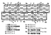
図6は従来の導波管スロットアレイアンテナを示す図である。図において1は放射スロット、2は放射用方形導波管、3は放射用方形導波管2へ電力を供給する給電スロット、4は給電用方形導波管、5a,5b,5c,5dはアレイを構成するサブアレイ、6aおよび6bは放射用方形導波管の管軸方向のサブアレイとサブアレイの間の管壁である。
【0003】
次に動作について説明する。尚、動作についてはアンテナより電波が放射する場合について述べる。給電用方形導波管4に入力された電磁波は、給電スロット3により放射用方形導波管2に入力される。放射用方形導波管2に入力された電磁波は放射用方形導波管2の管軸方向の長さを1/2管内波長の整数倍とすることにより内部に定在波を発生させる。この定在波は放射用方形導波管2の端部より1/4管内波長離れた位置から1/2管内波長ごとの位置において定在波の振幅が最大となる。この振幅最大の位置に放射スロット1を設けることで放射スロット1上に印加される電界が最大となり、空間へ電磁波が放射される。
【0004】
放射スロットと放射スロットの間隔Wはひとつの放射用方形導波管2内では1/2管内波長と等間隔であるが、放射用方形導波管の管軸方向のサブアレイ5aとサブアレイ5bおよびサブアレイ5cとサブアレイ5dの接合部の両側においては、導波管の管壁6a,6bの厚みtだけスロットの配列間隔が大きくなり、図7に示すように周期性によるサイドローブの上昇が生じていた。
【0005】
【発明が解決しようとする課題】
従来の導波管スロットアレイアンテナにおいては、ひとつの放射用導波管当りのスロット数が同じサブアレイを平面状に配列することにより構成していたため、放射用方形導波管の管軸方向のサブアレイとサブアレイの間のすべての導波管の管壁は同一線上に位置するため、周期的にスロットの配列間隔が広がってしまい、周期性によるサイドローブの上昇が生じていた。
【0006】
【課題を解決するための手段】
第1の発明による導波管スロットアレイアンテナは上述の問題を解決するために、導波管の管軸方向のサブアレイとサブアレイの間のすべての導波管の管壁が同一線上に並ばないように、サブアレイを導波管の管軸方向にずらして配列したものである。
【0007】
第2の発明による導波管スロットアレイアンテナは上述の問題を解決するために、導波管の管軸方向のサブアレイとサブアレイの間のすべての導波管の管壁が同一線上に並ばないように、サブアレイを導波管の管軸方向に1/2管内波長の整数倍ずらして配列したものである。
【0008】
また、第3の発明による導波管スロットアレイアンテナは上述の問題を解決するために、ひとつの放射導波管内に配置するスロット数を変化させてサブアレイを構成することにより、すべての導波管の管軸方向のサブアレイとサブアレイの間のすべての導波管の管壁が同一線上に並ばないようにサブアレイを配列したものである。
【0009】
また、第4の発明による導波管スロットアレイアンテナは上述の問題を解決するために、放射導波管を導波管の管軸方向にずらして配置することにより、すべての導波管の管軸方向のサブアレイとサブアレイの間のすべての導波管の管壁が同一線上に並ばないようにサブアレイを配列したものである。
【0010】
また、第5の発明による導波管スロットアレイアンテナは上述の問題を解決するために、放射導波管を導波管の管軸方向に1/2管内波長の整数倍ずらして配置することにより、すべての導波管の管軸方向のサブアレイとサブアレイの間のすべての導波管の管壁が同一線上に並ばないようにサブアレイを配列したものである。
【0011】
【発明の実施の形態】
実施の形態1.
図1はこの発明の実施の形態1を示す導波管スロットアレイアンテナである。図中符号は図6と同じである。
【0012】
次に動作について説明する。給電用方形導波管4から電磁波が入力され、放射スロット1から電磁波が放射される動作については従来例と同じである。図1においては、導波管スロットアレイアンテナのサブアレイ5a,5b,5c,5dを導波管の管軸方向にずらして配置することにより、放射用方形導波管の管軸方向のスロットの配列の周期性が緩和され、サイドローブを低減することが可能である。
【0013】
実施の形態2.
図2はこの発明の実施の形態2を示す導波管スロットアレイアンテナである。図中符号は図6と同じである。
【0014】
次に動作について説明する。給電用方形導波管4から電磁波が入力され、放射スロット1から電磁波が放射される動作については従来例と同じである。図2においては、導波管スロットアレイアンテナのサブアレイ5a,5b,5c,5dを導波管の管軸方向に1/2管内波長の整数倍ずらして配置することにより、放射用方形導波管の管軸方向のスロットの配列の周期性が緩和され、サイドローブを低減することが可能である。また、1/2管内波長の整数倍ずらして配列することにより、給電スロットと給電用方形導波管の位置は変更する必要がなく従来と同じ給電スロットおよび給電用方形導波管が使用できるため、給電回路の設計が容易である。
【0015】
実施の形態3.
図3はこの発明の実施の形態3を示す導波管スロットアレイアンテナである。図中符号は図6と同じである。
【0016】
次に動作ついて説明する。給電用方形導波管4から電磁波が入力され、放射スロット1から電磁波が放射される動作については従来例と同じである。図3においては、導波管スロットアレイアンテナのひとつの放射用方形導波管2に配置するスロット数を例えばサブアレイ5a,5bでは7素子、5cでは6素子、5dでは8素子と変化させて構成することにより、導波管の管軸方向のサブアレイ5aとサブアレイ5bおよびサブアレイ5aとサブアレイ5bの間の導波管の管壁6a,6bが同一線上に並ばないようにサブアレイを配列することにより、放射用方形導波管の管軸方向のスロットの配列の周期性が緩和され、サイドローブを低減することが可能である。また、給電スロットと給電用方形導波管の位置は変更する必要がなく従来と同じ給電スロットおよび給電用方形導波管が使用できるため、給電回路の設計が容易である。また、外形形状が従来例と同じであるため、アンテナの取り付け法も従来例と同じ方法とすることが可能である。
【0017】
実施の形態4.
図4はこの発明の実施の形態4を示す導波管スロットアレイアンテナである。図中符号は図6と同じである。
【0018】
次に動作について説明する。給電用方形導波管4から電磁波が入力され、放射スロット1から電磁波が放射される動作については従来例と同じである。図4においては、放射用方形導波管を導波管の管軸方向にずらして配置し、ひとつのサブアレイを構成し、上記サブアレイを平面状に多数配列することにより、放射用方形導波管の管軸方向のスロットの配列の周期性が緩和され、サイドローブを低減することが可能である。
【0019】
実施の形態5.
図5はこの発明の実施の形態5を示す導波管スロットアレイアンテナである。図中符号は図6と同じである。
【0020】
次に動作について説明する。給電用方形導波管4から電磁波が入力され、放射スロット1から電磁波が放射される動作については従来例と同じである。図5においては、放射用方形導波管を導波管の管軸方向に1/2管内波長の整数倍ずらして配置し、ひとつのサブアレイを構成し、上記サブアレイを平面状に多数配列することにより、放射用方形導波管の管軸方向のスロットの配列の周期性が緩和され、サイドローブを低減することが可能である。また、放射用方形導波管を導波管の管軸方向に1/2管内波長の整数倍ずらして配置することにより、給電スロットと給電用方形導波管の位置は変更する必要がなく従来と同じ給電スロットおよび給電用方形導波管が使用できるため、給電回路の設計が容易である。
【0021】
【発明の効果】
第1の発明によれば、複数の方形導波管を上記導波管の幅の狭い面が接するように配置し、上記各導波管の幅の広い面上に管軸に平行な複数の細長い放射スロットを1/2管内波長ごとに配置した導波管スロットアレイアンテナをひとつのサブアレイとし、上記サブアレイを平面状に多数配列した導波管スロットアレイアンテナにおいて、導波管の管軸方向のサブアレイとサブアレイの間の導波管の管壁が同一線上に並ばないように、サブアレイを導波管の管軸方向にずらして配列することにより、放射用方形導波管の管軸方向のスロットの配列の周期性が緩和され、サイドローブを低減することが可能である。
【0022】
また、第2の発明によれば、複数の方形導波管を上記導波管の幅の狭い面が接するように配置し、上記各導波管の幅の広い面上に管軸に平行な複数の細長い放射スロットを1/2管内波長ごとに配置した導波管スロットアレイアンテナをひとつのサブアレイとし、上記サブアレイを平面状に多数配列した導波管スロットアレイアンテナにおいて、導波管の管軸方向のサブアレイとサブアレイの間の導波管の管壁がすべて同一線上に並ばないように、サブアレイを導波管の管軸方向に1/2管内波長の整数倍ずらして配列することにより、放射用方形導波管の管軸方向のスロットの配列の周期性が緩和され、サイドローブを低減することが可能である。また、1/2管内波長の整数倍ずらして配列することにより、給電スロットと給電用方形導波管の位置は変更する必要がなく従来と同じ給電スロットおよび給電用方形導波管が使用できるため、給電回路の設計が容易である。
【0023】
また、第3の発明によれば、複数の方形導波管を上記導波管の幅の狭い面が接するように配置し、上記各導波管の幅の広い面上に管軸に平行な複数の細長い放射スロットを1/2管内波長ごとに配置した導波管スロットアレイアンテナをひとつのサブアレイとし、上記サブアレイを平面状に多数配列した導波管スロットアレイアンテナにおいて、ひとつの導波管内に配置するスロット数を変化させてサブアレイを構成することにより、導波管の管軸方向のサブアレイとサブアレイの間の導波管の管壁がすべて同一線上に並ばないようにサブアレイを配列することにより、放射用方形導波管の管軸方向のスロットの配列の周期性が緩和され、サイドローブを低減することが可能である。また、給電スロットと給電用方形導波管の位置は変更する必要がなく従来と同じ給電スロットおよび給電用方形導波管が使用できるため、給電回路の設計が容易である。また、外形形状が従来例と同じであるため、アンテナの取り付け法も従来例と同じ方法とすることが可能である。
【0024】
また、第4の発明によれば、複数の方形導波管を上記導波管の幅の狭い面が接するように配置し、上記各導波管の幅の広い面上に管軸に平行な複数の細長い放射スロットを1/2管内波長ごとに配置した導波管スロットアレイアンテナにおいて、上記各方形導波管を導波管の管軸方向にずらして配置し、ひとつのサブアレイを構成し、上記サブアレイを平面状に多数配列することにより、放射用方形導波管の管軸方向のスロットの配列の周期性が緩和され、サイドローブを低減することが可能である。
【0025】
また、第5の発明によれば、複数の方形導波管を上記導波管の幅の狭い面が接するように配置し、上記各導波管の幅の広い面上に管軸に平行な複数の細長い放射スロットを1/2管内波長ごとに配置した導波管スロットアレイアンテナにおいて、上記各方形導波管を導波管の管軸方向に1/2管内波長の整数倍ずらして配置し、ひとつのサブアレイを構成し、上記サブアレイを平面状に多数配列することにより、放射用方形導波管の管軸方向のスロットの配列の周期性が緩和され、サイドローブを低減することが可能である。また、放射用方形導波管を管軸方向に1/2管内波長の整数倍ずらして配置することにより、給電スロットと給電用方形導波管の位置は変更する必要がなく従来と同じ給電スロットおよび給電用方形導波管が使用できるため、給電回路の設計が容易である。
【図面の簡単な説明】
【図1】 この発明の実施の形態1に係る導波管スロットアレイアンテナを示す図である。
【図2】 この発明の実施の形態2に係る導波管スロットアレイアンテナを示す図である。
【図3】 この発明の実施の形態3に係る導波管スロットアレイアンテナを示す図である。
【図4】 この発明の実施の形態4に係る導波管スロットアレイアンテナを示す図である。
【図5】 この発明の実施の形態5に係る導波管スロットアレイアンテナを示す図である。
【図6】 従来の導波管スロットアレイアンテナを示す図である。
【図7】 従来の導波管スロットアレイアンテナの放射パターンを示す図である。[0001]
BACKGROUND OF THE INVENTION
The present invention relates to a waveguide slot array antenna capable of reducing a side lobe level of a radiation pattern.
[0002]
[Prior art]
FIG. 6 is a diagram showing a conventional waveguide slot array antenna. In the figure, 1 is a radiating slot, 2 is a radiating rectangular waveguide, 3 is a feeding slot for supplying power to the radiating
[0003]
Next, the operation will be described. The operation will be described for the case where radio waves are radiated from the antenna. The electromagnetic wave input to the feeding rectangular waveguide 4 is input to the radiating
[0004]
The spacing W between the radiation slots is equal to the ½ in-tube wavelength in one radiation
[0005]
[Problems to be solved by the invention]
In the conventional waveguide slot array antenna, since the sub-arrays having the same number of slots per one radiating waveguide are arranged in a plane, the sub-array in the tube axis direction of the radiating rectangular waveguide is formed. Since the tube walls of all the waveguides between the sub-array and the sub-array are located on the same line, the slot arrangement interval periodically increases, and the side lobe rises due to the periodicity.
[0006]
[Means for Solving the Problems]
In order to solve the above-described problem, the waveguide slot array antenna according to the first invention is configured so that the tube walls of all the waveguides between the sub-arrays in the tube axis direction of the waveguide are not aligned on the same line. In addition, the subarrays are arranged while being shifted in the tube axis direction of the waveguide.
[0007]
In order to solve the above-described problem, the waveguide slot array antenna according to the second invention prevents all waveguide wall walls between the sub-arrays in the tube axis direction of the waveguide from being aligned on the same line. In addition, the subarrays are arranged in the direction of the tube axis of the waveguide while being shifted by an integral multiple of the ½ tube wavelength.
[0008]
Further, in order to solve the above-described problem, the waveguide slot array antenna according to the third aspect of the present invention is configured so that all the waveguides are formed by changing the number of slots arranged in one radiation waveguide. The subarrays are arranged so that the tube walls of all the waveguides between the subarrays in the tube axis direction are not aligned on the same line.
[0009]
Further, in order to solve the above-mentioned problem, the waveguide slot array antenna according to the fourth aspect of the invention is arranged by shifting the radiating waveguide in the tube axis direction of the waveguide, so that all the waveguide tubes are arranged. The subarrays are arranged so that the tube walls of all the waveguides between the subarrays in the axial direction are not aligned on the same line.
[0010]
Further, in order to solve the above-mentioned problem, the waveguide slot array antenna according to the fifth invention is arranged by shifting the radiation waveguide in the tube axis direction of the waveguide by an integral multiple of the ½ in-tube wavelength. The subarrays are arranged so that the tube walls of all the waveguides between the subarrays in the tube axis direction of all the waveguides are not aligned on the same line.
[0011]
DETAILED DESCRIPTION OF THE INVENTION
FIG. 1 shows a waveguide slot array antenna according to
[0012]
Next, the operation will be described. The operation in which an electromagnetic wave is input from the feeding rectangular waveguide 4 and the electromagnetic wave is radiated from the
[0013]
FIG. 2 shows a waveguide slot array antenna according to
[0014]
Next, the operation will be described. The operation in which an electromagnetic wave is input from the feeding rectangular waveguide 4 and the electromagnetic wave is radiated from the
[0015]
FIG. 3 shows a waveguide slot array antenna according to
[0016]
Next, the operation will be described. The operation in which an electromagnetic wave is input from the feeding rectangular waveguide 4 and the electromagnetic wave is radiated from the
[0017]
Embodiment 4 FIG.
FIG. 4 shows a waveguide slot array antenna according to Embodiment 4 of the present invention. The reference numerals in the figure are the same as those in FIG.
[0018]
Next, the operation will be described. The operation in which an electromagnetic wave is input from the feeding rectangular waveguide 4 and the electromagnetic wave is radiated from the
[0019]
Embodiment 5 FIG.
FIG. 5 shows a waveguide slot array antenna according to the fifth embodiment of the present invention. The reference numerals in the figure are the same as those in FIG.
[0020]
Next, the operation will be described. The operation in which an electromagnetic wave is input from the feeding rectangular waveguide 4 and the electromagnetic wave is radiated from the
[0021]
【The invention's effect】
According to the first invention, a plurality of rectangular waveguides are arranged so that the narrow surfaces of the waveguides are in contact with each other, and a plurality of parallel waveguides parallel to the tube axis are formed on the wide surfaces of the waveguides. A waveguide slot array antenna in which elongated radiation slots are arranged for each wavelength in the ½ tube is used as one subarray, and in the waveguide slot array antenna in which a large number of the subarrays are arranged in a plane, Slots in the axial direction of the rectangular waveguide for radiating by arranging the subarrays shifted in the axial direction of the waveguide so that the waveguide tube walls between the subarrays are not aligned on the same line. The periodicity of the arrangement is relaxed, and the side lobes can be reduced.
[0022]
According to the second invention, the plurality of rectangular waveguides are arranged so that the narrow surfaces of the waveguides are in contact with each other, and are parallel to the tube axis on the wide surfaces of the waveguides. A waveguide slot array antenna in which a plurality of elongated radiation slots are arranged for every ½ in-tube wavelength is used as one subarray, and in the waveguide slot array antenna in which a large number of the subarrays are arranged in a plane, the tube axis of the waveguide By arranging the subarrays so that the waveguide tube walls between the subarrays are not aligned on the same line, the subarrays are shifted in the tube axis direction of the waveguide by an integer multiple of the ½ tube wavelength. The periodicity of the arrangement of the slots in the tube axis direction of the rectangular waveguide can be relaxed, and the side lobes can be reduced. In addition, by arranging the wavelength shifted by an integral multiple of the ½ in-tube wavelength, it is not necessary to change the positions of the feeding slot and the feeding rectangular waveguide, and the same feeding slot and feeding rectangular waveguide as before can be used. The power supply circuit is easy to design.
[0023]
According to the third invention, the plurality of rectangular waveguides are arranged so that the narrow surfaces of the waveguides are in contact with each other, and are parallel to the tube axis on the wide surfaces of the waveguides. A waveguide slot array antenna in which a plurality of elongated radiation slots are arranged for each wavelength in a ½ tube is used as one subarray, and in the waveguide slot array antenna in which a large number of the subarrays are arranged in a plane, By arranging the subarray so that the waveguide tube wall between the subarrays in the tube axis direction of the waveguide is not aligned on the same line by configuring the subarray by changing the number of slots to be arranged The periodicity of the arrangement of the slots in the tube axis direction of the radiating rectangular waveguide can be relaxed, and the side lobes can be reduced. Further, it is not necessary to change the positions of the power supply slot and the power supply rectangular waveguide, and the same power supply slot and power supply square waveguide can be used as in the prior art, so that the power supply circuit can be easily designed. Further, since the outer shape is the same as that of the conventional example, the antenna can be attached in the same manner as the conventional example.
[0024]
According to the fourth invention, a plurality of rectangular waveguides are arranged so that the narrow surfaces of the waveguides are in contact with each other, and are parallel to the tube axis on the wide surfaces of the waveguides. In a waveguide slot array antenna in which a plurality of elongated radiation slots are arranged for each half-tube wavelength, each of the rectangular waveguides is arranged shifted in the tube axis direction of the waveguide to constitute one subarray, By arranging a large number of the subarrays in a planar shape, the periodicity of the arrangement of the slots in the tube axis direction of the radiating rectangular waveguide can be relaxed, and the side lobes can be reduced.
[0025]
According to the fifth invention, a plurality of rectangular waveguides are arranged so that the narrow surfaces of the waveguides are in contact with each other, and the waveguides are parallel to the tube axis on the wide surfaces of the waveguides. In a waveguide slot array antenna in which a plurality of elongated radiating slots are arranged for each ½ tube wavelength, each of the rectangular waveguides is arranged shifted by an integral multiple of the ½ tube wavelength in the tube axis direction of the waveguide. By constructing one subarray and arranging a large number of the above subarrays in a plane, the periodicity of the arrangement of slots in the tube axis direction of the rectangular waveguide for radiation can be relaxed, and side lobes can be reduced. is there. In addition, by arranging the rectangular waveguide for radiation in the tube axis direction so as to be shifted by an integral multiple of the ½ in-tube wavelength, it is not necessary to change the positions of the feeding slot and the feeding rectangular waveguide. In addition, since a rectangular waveguide for feeding can be used, the feeding circuit can be easily designed.
[Brief description of the drawings]
FIG. 1 is a diagram showing a waveguide slot array antenna according to a first embodiment of the present invention.
FIG. 2 is a diagram showing a waveguide slot array antenna according to a second embodiment of the present invention.
FIG. 3 is a diagram showing a waveguide slot array antenna according to a third embodiment of the present invention.
FIG. 4 is a diagram showing a waveguide slot array antenna according to a fourth embodiment of the present invention.
FIG. 5 is a diagram showing a waveguide slot array antenna according to a fifth embodiment of the present invention.
FIG. 6 is a view showing a conventional waveguide slot array antenna.
FIG. 7 is a diagram showing a radiation pattern of a conventional waveguide slot array antenna.
Claims (2)
を1/2管内波長ごとに配置した導波管スロットアレイアンテナをひとつのサブアレイとし、上記サブアレイを平面状に多数配列して、それぞれのサブアレイに電力が給電される導波管スロットアレイアンテナにおいて、
放射用方形導波管の管軸方向に隣接するサブアレイとサブアレイの間の導波管端部の管壁からλ/4管内波長離れた位置に各隣接するサブアレイの導波管端部のスロットが設けられ、当該隣接するサブアレイの導波管端部のスロット間隔がλ/2を超えるように上記導波管端部の管壁の厚さが設定されるとともに、
上記導波管端部の管壁が同一線上に並ばないように、管軸の直交方向に隣接する上記サブアレイの導波管端部の管壁を、導波管の管軸方向に1/2管内波長の整数倍ずらして配列したことを特徴とする導波管スロットアレイアンテナ。A plurality of rectangular waveguides are arranged so that the narrow surfaces of the waveguides are in contact with each other, and a plurality of elongated radiation slots parallel to the tube axis are formed on the wide surfaces of the waveguides in the ½ tube. In the waveguide slot array antenna in which the waveguide slot array antenna arranged for each wavelength is set as one subarray, and a large number of the subarrays are arranged in a plane , and power is supplied to each subarray .
Slot waveguide end of the sub-arrays that each adjacent tube wall from lambda / 4 guide wavelength away waveguide ends between the sub-arrays and subarrays adjacent tube axis direction of the radiating rectangular waveguide And the thickness of the tube wall of the waveguide end is set so that the slot interval between the waveguide ends of the adjacent subarrays exceeds λ / 2,
As the tube wall of the waveguide end not aligned on the same line, the tube wall of the waveguide end of the adjacent subarrays in the direction perpendicular to the tube axis, in the tube axis direction of the waveguide 1/2 A waveguide slot array antenna, which is arranged with an integer multiple of the guide wavelength shifted.
を1/2管内波長ごとに配置した導波管スロットアレイアンテナをひとつのサブアレイとし、上記サブアレイを平面状に多数配列して、それぞれのサブアレイに電力が給電される導波管スロットアレイアンテナにおいて、
放射用方形導波管の管軸方向に隣接するサブアレイとサブアレイの間の導波管端部の管壁からλ/4管内波長離れた位置に各隣接するサブアレイの導波管端部のスロットが設けられ、当該隣接するサブアレイの導波管端部のスロット間隔がλ/2を超えるように上記導波管端部の管壁の厚さが設定されるとともに、
上記導波管端部の管壁がすべて同一線上に並ばないように、管軸の直交方向に隣接する上記サブアレイの導波管端部の管壁を、導波管の管軸方向に1/2管内波長の整数倍ずらして配列したことを特徴とする導波管スロットアレイアンテナ。A plurality of rectangular waveguides are arranged so that the narrow surfaces of the waveguides are in contact with each other, and a plurality of elongated radiation slots parallel to the tube axis are formed on the wide surfaces of the waveguides in the ½ tube. In the waveguide slot array antenna in which the waveguide slot array antenna arranged for each wavelength is set as one subarray, and a large number of the subarrays are arranged in a plane , and power is supplied to each subarray .
Slot waveguide end of the sub-arrays that each adjacent tube wall from lambda / 4 guide wavelength away waveguide ends between the sub-arrays and subarrays adjacent tube axis direction of the radiating rectangular waveguide And the thickness of the tube wall of the waveguide end is set so that the slot interval between the waveguide ends of the adjacent subarrays exceeds λ / 2,
As the tube wall of the waveguide end portion not arranged on all collinear, the tube wall of the waveguide end of the adjacent subarrays in the direction perpendicular to the tube axis, in the tube axis direction of the waveguide 1 / 2. A waveguide slot array antenna characterized by being shifted by an integral multiple of the in-tube wavelength .
Priority Applications (1)
| Application Number | Priority Date | Filing Date | Title |
|---|---|---|---|
| JP03832699A JP3812203B2 (en) | 1999-02-17 | 1999-02-17 | Waveguide slot array antenna |
Applications Claiming Priority (1)
| Application Number | Priority Date | Filing Date | Title |
|---|---|---|---|
| JP03832699A JP3812203B2 (en) | 1999-02-17 | 1999-02-17 | Waveguide slot array antenna |
Publications (3)
| Publication Number | Publication Date |
|---|---|
| JP2000236213A JP2000236213A (en) | 2000-08-29 |
| JP2000236213A5 JP2000236213A5 (en) | 2004-12-24 |
| JP3812203B2 true JP3812203B2 (en) | 2006-08-23 |
Family
ID=12522172
Family Applications (1)
| Application Number | Title | Priority Date | Filing Date |
|---|---|---|---|
| JP03832699A Expired - Fee Related JP3812203B2 (en) | 1999-02-17 | 1999-02-17 | Waveguide slot array antenna |
Country Status (1)
| Country | Link |
|---|---|
| JP (1) | JP3812203B2 (en) |
Cited By (3)
| Publication number | Priority date | Publication date | Assignee | Title |
|---|---|---|---|---|
| WO2009107216A1 (en) * | 2008-02-28 | 2009-09-03 | 三菱電機株式会社 | Waveguide slot array antenna apparatus |
| CN102859789A (en) * | 2012-05-30 | 2013-01-02 | 华为技术有限公司 | Antenna array, antenna device and base station |
| CN102983406B (en) * | 2005-09-13 | 2015-01-07 | 苹果公司 | Antenna |
Families Citing this family (8)
| Publication number | Priority date | Publication date | Assignee | Title |
|---|---|---|---|---|
| KR20040025113A (en) | 2002-09-18 | 2004-03-24 | 한국전자통신연구원 | Microstrip patch array antenna for suppressing side lobes |
| KR100724949B1 (en) | 2005-05-03 | 2007-06-04 | 삼성전자주식회사 | Method and Apparatus for multiplexing data and control information in wireless communication systems based on frequency division multiple access |
| EP1983614B1 (en) | 2006-02-06 | 2016-08-31 | Mitsubishi Electric Corporation | High frequency module |
| JP4602276B2 (en) * | 2006-03-23 | 2010-12-22 | 三菱電機株式会社 | Waveguide slot array antenna device |
| JP4996640B2 (en) * | 2009-03-10 | 2012-08-08 | 株式会社東芝 | Antenna device, radar device |
| JP5424954B2 (en) * | 2010-03-29 | 2014-02-26 | 三菱電機株式会社 | Waveguide slot array antenna |
| JP6082231B2 (en) * | 2012-10-31 | 2017-02-15 | 日本無線株式会社 | Waveguide slot antenna |
| CN106356642B (en) * | 2016-10-27 | 2023-06-13 | 成都雷电微力科技股份有限公司 | Dielectric waveguide split array antenna with metal hollow waveguide series feed |
-
1999
- 1999-02-17 JP JP03832699A patent/JP3812203B2/en not_active Expired - Fee Related
Cited By (5)
| Publication number | Priority date | Publication date | Assignee | Title |
|---|---|---|---|---|
| CN102983406B (en) * | 2005-09-13 | 2015-01-07 | 苹果公司 | Antenna |
| WO2009107216A1 (en) * | 2008-02-28 | 2009-09-03 | 三菱電機株式会社 | Waveguide slot array antenna apparatus |
| US8599090B2 (en) | 2008-02-28 | 2013-12-03 | Mitsubishi Electric Corporation | Waveguide slot array antenna apparatus |
| CN102859789A (en) * | 2012-05-30 | 2013-01-02 | 华为技术有限公司 | Antenna array, antenna device and base station |
| US10181657B2 (en) | 2012-05-30 | 2019-01-15 | Huawei Technologies Co., Ltd. | Antenna array, antenna apparatus, and base station |
Also Published As
| Publication number | Publication date |
|---|---|
| JP2000236213A (en) | 2000-08-29 |
Similar Documents
| Publication | Publication Date | Title |
|---|---|---|
| US8134514B2 (en) | Coaxial line slot array antenna and method for manufacturing the same | |
| KR100574228B1 (en) | Hexagonal Array Structure Of Dielectric Rod To Shape Flat-Topped Element Pattern | |
| JP4602276B2 (en) | Waveguide slot array antenna device | |
| JP5686927B2 (en) | Waveguide slot array antenna device | |
| JP3812203B2 (en) | Waveguide slot array antenna | |
| US20140375525A1 (en) | Antenna with fifty percent overlapped subarrays | |
| CN108598702B (en) | Ultra-wideband low-profile antenna array structure | |
| GB2208969A (en) | Slot antenna | |
| JP2013187752A (en) | Waveguide slot array antenna apparatus | |
| JP5495955B2 (en) | Waveguide slot array antenna | |
| AU623820B2 (en) | Array antenna with slot radiators offset by inclination | |
| JPH0590833A (en) | Slot radiator structure for adjusting vane | |
| JP2000236213A5 (en) | ||
| NO319613B1 (en) | Mid-length longitudinal shunt slot fed by a tuned iris with an offset comb | |
| JPH01173907A (en) | Plane antenna | |
| JP2003198242A (en) | Slotted waveguide array antenna | |
| CN109994840B (en) | Brick-type arranged strip line feed frequency scanning antenna array | |
| JP3893726B2 (en) | Waveguide slot array antenna | |
| JP2526393B2 (en) | Parallel plate slot antenna | |
| JP2010177983A (en) | Patch array antenna | |
| JP4409789B2 (en) | Antenna device | |
| JP3895285B2 (en) | Waveguide array antenna | |
| JP3848944B2 (en) | Waveguide slot array antenna | |
| JP4937273B2 (en) | Coaxial line slot array antenna and manufacturing method thereof | |
| KR102462315B1 (en) | Waveguide Slot Array Beamsteering Antenna |
Legal Events
| Date | Code | Title | Description |
|---|---|---|---|
| A521 | Written amendment |
Free format text: JAPANESE INTERMEDIATE CODE: A523 Effective date: 20040120 |
|
| A621 | Written request for application examination |
Free format text: JAPANESE INTERMEDIATE CODE: A621 Effective date: 20040120 |
|
| RD01 | Notification of change of attorney |
Free format text: JAPANESE INTERMEDIATE CODE: A7421 Effective date: 20040623 |
|
| A977 | Report on retrieval |
Free format text: JAPANESE INTERMEDIATE CODE: A971007 Effective date: 20050826 |
|
| A131 | Notification of reasons for refusal |
Free format text: JAPANESE INTERMEDIATE CODE: A131 Effective date: 20050906 |
|
| A521 | Written amendment |
Free format text: JAPANESE INTERMEDIATE CODE: A523 Effective date: 20051102 |
|
| TRDD | Decision of grant or rejection written | ||
| A01 | Written decision to grant a patent or to grant a registration (utility model) |
Free format text: JAPANESE INTERMEDIATE CODE: A01 Effective date: 20060509 |
|
| A61 | First payment of annual fees (during grant procedure) |
Free format text: JAPANESE INTERMEDIATE CODE: A61 Effective date: 20060522 |
|
| FPAY | Renewal fee payment (event date is renewal date of database) |
Free format text: PAYMENT UNTIL: 20100609 Year of fee payment: 4 |
|
| FPAY | Renewal fee payment (event date is renewal date of database) |
Free format text: PAYMENT UNTIL: 20100609 Year of fee payment: 4 |
|
| FPAY | Renewal fee payment (event date is renewal date of database) |
Free format text: PAYMENT UNTIL: 20110609 Year of fee payment: 5 |
|
| FPAY | Renewal fee payment (event date is renewal date of database) |
Free format text: PAYMENT UNTIL: 20120609 Year of fee payment: 6 |
|
| FPAY | Renewal fee payment (event date is renewal date of database) |
Free format text: PAYMENT UNTIL: 20130609 Year of fee payment: 7 |
|
| LAPS | Cancellation because of no payment of annual fees |