EP2846249B2 - Verzahnmaschine mit multitouch-fähigem Display - Google Patents
Verzahnmaschine mit multitouch-fähigem Display Download PDFInfo
- Publication number
- EP2846249B2 EP2846249B2 EP14180541.6A EP14180541A EP2846249B2 EP 2846249 B2 EP2846249 B2 EP 2846249B2 EP 14180541 A EP14180541 A EP 14180541A EP 2846249 B2 EP2846249 B2 EP 2846249B2
- Authority
- EP
- European Patent Office
- Prior art keywords
- display
- gear cutting
- machine
- cutting machine
- window
- Prior art date
- Legal status (The legal status is an assumption and is not a legal conclusion. Google has not performed a legal analysis and makes no representation as to the accuracy of the status listed.)
- Active
Links
Images


Classifications
-
- G—PHYSICS
- G05—CONTROLLING; REGULATING
- G05B—CONTROL OR REGULATING SYSTEMS IN GENERAL; FUNCTIONAL ELEMENTS OF SUCH SYSTEMS; MONITORING OR TESTING ARRANGEMENTS FOR SUCH SYSTEMS OR ELEMENTS
- G05B19/00—Program-control systems
- G05B19/02—Program-control systems electric
- G05B19/18—Numerical control [NC], i.e. automatically operating machines, in particular machine tools, e.g. in a manufacturing environment, so as to execute positioning, movement or co-ordinated operations by means of program data in numerical form
- G05B19/188—Numerical control [NC], i.e. automatically operating machines, in particular machine tools, e.g. in a manufacturing environment, so as to execute positioning, movement or co-ordinated operations by means of program data in numerical form characterised by special applications and not provided for in the relevant subclasses, (e.g. making dies, filament winding)
-
- B—PERFORMING OPERATIONS; TRANSPORTING
- B23—MACHINE TOOLS; METAL-WORKING NOT OTHERWISE PROVIDED FOR
- B23F—MAKING GEARS OR TOOTHED RACKS
- B23F23/00—Accessories or equipment combined with or arranged in, or specially designed to form part of, gear-cutting machines
-
- G—PHYSICS
- G05—CONTROLLING; REGULATING
- G05B—CONTROL OR REGULATING SYSTEMS IN GENERAL; FUNCTIONAL ELEMENTS OF SUCH SYSTEMS; MONITORING OR TESTING ARRANGEMENTS FOR SUCH SYSTEMS OR ELEMENTS
- G05B19/00—Program-control systems
- G05B19/02—Program-control systems electric
- G05B19/18—Numerical control [NC], i.e. automatically operating machines, in particular machine tools, e.g. in a manufacturing environment, so as to execute positioning, movement or co-ordinated operations by means of program data in numerical form
- G05B19/409—Numerical control [NC], i.e. automatically operating machines, in particular machine tools, e.g. in a manufacturing environment, so as to execute positioning, movement or co-ordinated operations by means of program data in numerical form characterised by using manual data input [MDI] or by using control panel, e.g. controlling functions with the panel; characterised by control panel details or by setting parameters
-
- G—PHYSICS
- G05—CONTROLLING; REGULATING
- G05B—CONTROL OR REGULATING SYSTEMS IN GENERAL; FUNCTIONAL ELEMENTS OF SUCH SYSTEMS; MONITORING OR TESTING ARRANGEMENTS FOR SUCH SYSTEMS OR ELEMENTS
- G05B2219/00—Program-control systems
- G05B2219/30—Nc systems
- G05B2219/35—Nc in input of data, input till input file format
- G05B2219/35488—Graphical user interface, labview
-
- G—PHYSICS
- G05—CONTROLLING; REGULATING
- G05B—CONTROL OR REGULATING SYSTEMS IN GENERAL; FUNCTIONAL ELEMENTS OF SUCH SYSTEMS; MONITORING OR TESTING ARRANGEMENTS FOR SUCH SYSTEMS OR ELEMENTS
- G05B2219/00—Program-control systems
- G05B2219/30—Nc systems
- G05B2219/36—Nc in input of data, input key till input tape
- G05B2219/36137—Configuration of display device, operator panel
-
- G—PHYSICS
- G05—CONTROLLING; REGULATING
- G05B—CONTROL OR REGULATING SYSTEMS IN GENERAL; FUNCTIONAL ELEMENTS OF SUCH SYSTEMS; MONITORING OR TESTING ARRANGEMENTS FOR SUCH SYSTEMS OR ELEMENTS
- G05B2219/00—Program-control systems
- G05B2219/30—Nc systems
- G05B2219/36—Nc in input of data, input key till input tape
- G05B2219/36146—Group windows into coherent sets to facilate a task
-
- G—PHYSICS
- G05—CONTROLLING; REGULATING
- G05B—CONTROL OR REGULATING SYSTEMS IN GENERAL; FUNCTIONAL ELEMENTS OF SUCH SYSTEMS; MONITORING OR TESTING ARRANGEMENTS FOR SUCH SYSTEMS OR ELEMENTS
- G05B2219/00—Program-control systems
- G05B2219/30—Nc systems
- G05B2219/36—Nc in input of data, input key till input tape
- G05B2219/36168—Touchscreen
-
- G—PHYSICS
- G05—CONTROLLING; REGULATING
- G05B—CONTROL OR REGULATING SYSTEMS IN GENERAL; FUNCTIONAL ELEMENTS OF SUCH SYSTEMS; MONITORING OR TESTING ARRANGEMENTS FOR SUCH SYSTEMS OR ELEMENTS
- G05B2219/00—Program-control systems
- G05B2219/30—Nc systems
- G05B2219/36—Nc in input of data, input key till input tape
- G05B2219/36198—Gear, thread cutting
-
- G—PHYSICS
- G05—CONTROLLING; REGULATING
- G05B—CONTROL OR REGULATING SYSTEMS IN GENERAL; FUNCTIONAL ELEMENTS OF SUCH SYSTEMS; MONITORING OR TESTING ARRANGEMENTS FOR SUCH SYSTEMS OR ELEMENTS
- G05B2219/00—Program-control systems
- G05B2219/30—Nc systems
- G05B2219/36—Nc in input of data, input key till input tape
- G05B2219/36493—Position of stillstand if no reverse and acceleration only, data compression
-
- G—PHYSICS
- G05—CONTROLLING; REGULATING
- G05B—CONTROL OR REGULATING SYSTEMS IN GENERAL; FUNCTIONAL ELEMENTS OF SUCH SYSTEMS; MONITORING OR TESTING ARRANGEMENTS FOR SUCH SYSTEMS OR ELEMENTS
- G05B2219/00—Program-control systems
- G05B2219/30—Nc systems
- G05B2219/36—Nc in input of data, input key till input tape
- G05B2219/36494—Record position and inclination of tool, wrist
-
- G—PHYSICS
- G05—CONTROLLING; REGULATING
- G05B—CONTROL OR REGULATING SYSTEMS IN GENERAL; FUNCTIONAL ELEMENTS OF SUCH SYSTEMS; MONITORING OR TESTING ARRANGEMENTS FOR SUCH SYSTEMS OR ELEMENTS
- G05B2219/00—Program-control systems
- G05B2219/30—Nc systems
- G05B2219/36—Nc in input of data, input key till input tape
- G05B2219/36499—Part program, workpiece, geometry and environment, machining dependant, combine
-
- G—PHYSICS
- G05—CONTROLLING; REGULATING
- G05B—CONTROL OR REGULATING SYSTEMS IN GENERAL; FUNCTIONAL ELEMENTS OF SUCH SYSTEMS; MONITORING OR TESTING ARRANGEMENTS FOR SUCH SYSTEMS OR ELEMENTS
- G05B2219/00—Program-control systems
- G05B2219/30—Nc systems
- G05B2219/36—Nc in input of data, input key till input tape
- G05B2219/36506—Store in Rom and Ram
-
- G—PHYSICS
- G05—CONTROLLING; REGULATING
- G05B—CONTROL OR REGULATING SYSTEMS IN GENERAL; FUNCTIONAL ELEMENTS OF SUCH SYSTEMS; MONITORING OR TESTING ARRANGEMENTS FOR SUCH SYSTEMS OR ELEMENTS
- G05B2219/00—Program-control systems
- G05B2219/30—Nc systems
- G05B2219/36—Nc in input of data, input key till input tape
- G05B2219/36542—Cryptography, encrypt, access, authorize with key, code, password
-
- G—PHYSICS
- G06—COMPUTING OR CALCULATING; COUNTING
- G06F—ELECTRIC DIGITAL DATA PROCESSING
- G06F3/00—Input arrangements for transferring data to be processed into a form capable of being handled by the computer; Output arrangements for transferring data from processing unit to output unit, e.g. interface arrangements
- G06F3/01—Input arrangements or combined input and output arrangements for interaction between user and computer
- G06F3/048—Interaction techniques based on graphical user interfaces [GUI]
- G06F3/0487—Interaction techniques based on graphical user interfaces [GUI] using specific features provided by the input device, e.g. functions controlled by the rotation of a mouse with dual sensing arrangements, or of the nature of the input device, e.g. tap gestures based on pressure sensed by a digitiser
- G06F3/0488—Interaction techniques based on graphical user interfaces [GUI] using specific features provided by the input device, e.g. functions controlled by the rotation of a mouse with dual sensing arrangements, or of the nature of the input device, e.g. tap gestures based on pressure sensed by a digitiser using a touch-screen or digitiser, e.g. input of commands through traced gestures
Definitions
- the present invention relates to a gear cutting machine with a machine controller and at least one display for showing machine-relevant parameters.
- Gear cutting machines currently include a display that is used to display various operating parameters of the gear cutting machine. Necessary entries for controlling the gear cutting machine are made by the operator via a separate external control element.
- the control element comprises one or more mechanical keys or key fields, via which certain control commands can be entered or configuration parameters can be programmed by pressing them.
- the operator can use the display element to check the entered control commands or read the current operating parameters.
- the display is fixed and cannot be individually adapted to the individual user. Although such a machine control or operation fulfills its purpose, it is not particularly convenient.
- a multi-touch control for an injection molding machine is from DE 10 2010 051 639 A1 known. Also the DE 10 2009 017 030 A1 proposes realizing the industrial control of an industrial machine using a multi-touch capable surface. Another application for industrial machines is disclosed in the article "Reduced to the best. Prime cup, white paper multitouch in industrial applications" from 03/21/2011.
- the object of the present invention consists in demonstrating a gear cutting machine that enables better and more comfortable handling.
- a gear cutting machine with a machine controller and at least one display for displaying machine-relevant parameters is proposed.
- the at least one display is multi-touch capable and an operator input for controlling the gear cutting machine occurs at least partially by touching the display.
- Screen and multi-touch screen are particularly preferably combined and are one above the other.
- the operator can enter corresponding control commands into the gear cutting machine on the basis of various multi-finger gestures, which allows particularly convenient operation of the gear cutting machine.
- the operator can tap, move, resize, rotate, or select multiple objects on the objects displayed on the screen.
- Popular multi-finger applications are zooming and rotating objects by moving two fingers away from each other or rotating them towards each other.
- the at least one multi-touch capable display can have a resistive, capacitive, optical or inductive touch-sensitive surface, for example. It is conceivable that the gear cutting machine has both non-touch-enabled and touch-enabled displays.
- the use of a multi-touch capable display not only allows for an optimized and more extensive human-machine interaction, but also opens up extensive possibilities for the implementation of a new type of operating concept. It is conceivable that the visual display representation of the one or more machine parameters can be configured individually. Ideally, the visual display of one or more machine-relevant parameters can be configured by means of input via the touch-sensitive display with regard to the display properties and with regard to the scope of the information displayed.
- the number of parameters can be varied in order to guarantee the operator a more comprehensive information display if desired or to maintain the clarity of the information displayed by reducing the information content.
- the operator has the option of selecting or temporarily displaying every available machine-relevant parameter for the display. Unnecessary or less relevant parameters can be hidden or displayed in the background.
- the adjustment can be made via the multi-touch display.
- means are provided which allow a user-dependent display of one or more machine-relevant parameters.
- Different display skins/themes can preferably be stored in a display profile.
- the gear cutting machine has means for operator recognition and/or operator verification/authentication. Ideally, after entering the user ID, a user-dependent display is automatically generated or displayed.
- one or more operator profiles can be stored, which can be called up manually or automatically by the operator and automatically display corresponding displays.
- the user can thus configure the preferred type of display once and store it in his personal profile.
- a user-dependent display representation is particularly advantageous when the gear cutting machine is to be operated by several users. By selecting the relevant profile, each operator can call up their individual display.
- the display representation is in divided into one or more windows by the multi-touch capable display.
- Each window is used to display a certain number of machine-relevant parameters.
- each window can be individually configured via the touch display with regard to the window size and with regard to the type and/or scope of the displayed machine-relevant parameters.
- the windows can be placed anywhere on the display, for example. The same applies to the window size, which can be changed particularly easily using a multi-finger gesture.
- the display representation is not only divided into one or more windows, but into one or more virtual screens, between which it is possible to scroll back and forth with the help of a swiping movement.
- the machine control is designed in such a way that one or more third-party applications can be installed and executed on the machine.
- This allows the gear cutting machine to be expanded in terms of functionality compared to the basic functions provided by the manufacturer by installing various third-party applications.
- the one or more installed and executable third-party applications can access the input and output option of the touch-sensitive display. The customer thus has the option of adapting or expanding the functionality of the gear cutting machine to his personal requirements using his own applications.
- the gear cutting machine can have one or more storage means for storing one or more video files.
- the machine control can be used to play back one or more stored video files via the multi-touch display.
- the video files can preferably contain training films that offer the customer a video-guided introduction to the function and configuration of the gear cutting machine. Individual video files can be executed by the operator via the multi-touch display and displayed via the display element.
- Various data formats can be stored on the storage medium.
- everything that a current operating system, such as Windows 7, can process can be stored and played back.
- These can be PDF documents, CAD data, images, videos, etc.
- the gear cutting machine can have one or more video recording devices. It is conceivable that such internal video cameras are arranged in the area of the machine table or workpiece holder and/or tool holder and record individual gearing processes. The processes carried out on the gear cutting machine are often not accessible or visible from the machine console of the gear cutting machine. With the help of the internal video camera, the processes can be conveniently shown on the display and offer the user an insight into the gear cutting process.
- the image files provided by the one or more internal video cameras can also be recorded on an internal or alternatively external storage medium and made available for later playback via the multi-touch display or another display.
- the Figures 1 to 5 show different representations of the user interface of the gear cutting machine according to the invention, wherein the displayed objects on the user interface can be selected, moved, enlarged or reduced, rotated, etc. by touching the multi-touch capable display of the gear cutting machine. It is preferably operated by simply touching the display or using multi-finger gestures.
- the multi-touch surface offers different operating options, for example a "touch and hold", only “touch” or a “touch and wipe” function.
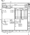
- buttons 10 are fixed at the top, right and bottom of the screen, which allow direct access to a submenu (setup, first part, configuration, etc.) or the immediate execution of a machine command (e.g. "Alarm Cancel") when touched .
- the display of these icons is predefined and identical for each individually designed user interface.
- the icons are part of the so-called main window.
- sub-windows 20 are displayed which are identical in size and arranged symmetrically to each other. These sub-windows are used to display different machine parameters, with different sub-windows, ie different process views or sub-categories, showing. The operator can customize the graphic design and the window content. The information displayed is only configured for these subcategories or subwindows for which such a selection option makes sense. The number of sub-windows displayed can also be freely defined.
- figure 1 shows four sub-windows, whereby the first window relates to the current process progress of workpiece machining.
- the axis display is shown in the second sub-window on the right, which outputs the current actual value and the planned value for a configured number of machine-controlled CNC axes distance to go for gear machining.
- the two windows below on the left show collision monitoring, which is active during the gear cutting process and monitors individual machine components, such as the machining head, a device for clamping the workpiece and the workpiece itself, for mutual collisions. To this end, different parameters and, if applicable, an imminent risk of collision are displayed. To the right is a process view showing the individual performance parameters of the axis drives used.
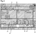
- FIG 2 now shows the process view selection bar 30 at the bottom edge of the screen, which is only highlighted here in this representation for a better overview of the user interface.
- the process view selection bar is used to select the individual process views, ie the individual sub-windows, for display on the main screen.
- This process view selection bar can be rotated with a simple swipe movement until the desired sub-window is visible in the bar and can then be dragged into the main screen by touch.
- the selected sub-window can be positioned at the desired position in the main window.
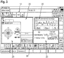
- figure 3 shows an individual, different arrangement of the individual process windows 20, which differs from that in figure 1 is not symmetrical.
- the window sizes of the process views have been changed and configured according to the preferences of the operator.
- figure 3 also shows that individual process views can be positioned not necessarily next to each other, but also one behind the other, with the touch-activated sub-window coming to the fore. It is also possible to prioritize a sub-window so that it always remains in the foreground.
- the individually designed user interface can be stored as a profile, ideally as a user profile, on the gear cutting machine and is available for later retrieval. Each operator can therefore quickly adapt the gear cutting machine to his needs by calling up a stored profile when starting up the gear cutting machine.
- the figure 3 shows three process views as an example, which show the balancing device, a torque display and also the collision monitoring.
- FIG. 4a On the other hand, only a process view 20, namely the axis display, is displayed in the main window. All other process views have been removed for reasons of clarity.
- the displayed information content of an individual process view 20, for example the axis display can be freely configured for certain process views 20.
- the axis display shows the X1, Z1, V1, A1 axis with their respective position. If more or fewer axes are to be displayed, the header 23 of the "Axis display" process view 20 is tapped. With an automatic flipping movement, the back of the window 21 is shown in accordance with Figure 4b displayed.
- the corresponding selection switches enable the individual selection of individual axes for overlaying in the window front 20 according to Figure 4a .
- axes X1, Z1, V1, A1 are activated and axes B1, C2 are deactivated.
- the information displayed can also be varied with regard to the selected axes. For example, different information is available for each axis in the "Columns" sub-item.
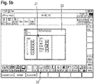
- FIGS. 5a , 5b show another example of an axis configuration with the associated selection window.
- the display of all available machine axes of the gear cutting machine was activated on the back of the window 21, whereby these are completely displayed in the main window of the window front 20 of the axis display.
Landscapes
- Engineering & Computer Science (AREA)
- Human Computer Interaction (AREA)
- Manufacturing & Machinery (AREA)
- Physics & Mathematics (AREA)
- General Physics & Mathematics (AREA)
- Automation & Control Theory (AREA)
- Mechanical Engineering (AREA)
- Numerical Control (AREA)
- User Interface Of Digital Computer (AREA)
- Crushing And Pulverization Processes (AREA)
Description
- Die vorliegende Erfindung betrifft eine Verzahnmaschine mit einer Maschinensteuerung sowie wenigstens einem Display zur Anzeige maschinenrelevanter Parameter. Derzeit umfassen Verzahnmaschinen ein Display, das zur Wiedergabe diverser Betriebsparameter der Verzahnmaschine genutzt wird. Notwendige Eingaben zur Steuerung der Verzahnmaschine werden über ein separates externes Bedienelement durch den Bediener getätigt. Das Bedienelement umfasst in der Regel ein oder mehrere mechanische Tasten bzw. Tastenfelder, über die durch Druckbetätigung gewisse Steuerbefehle eingebbar sind bzw. Konfigurationsparameter programmiert werden können. Der Bediener kann anhand des Displayelementes die eingegebenen Steuerbefehle überprüfen bzw. die aktuellen Betriebsparameter ablesen. Die Darstellung ist dabei fest vorgegeben und nicht individuell an den einzelnen Nutzer anpassbar. Ein solche Maschinensteuerung bzw. Bedienung erfüllt zwar ihren Zweck, ist jedoch nicht besonders komfortabel.
- Eine Multitouchsteueung für eine Spritzgiessmaschine ist aus der
DE 10 2010 051 639 A1 bekannt. Auch dieDE 10 2009 017 030 A1 schlägt vor, die Industriesteuerung einer Industriemaschine mittels einer multitouchfähigen Oberfläche zu verwirklichen. Ein weiterer Anwendungsfall für Industriemaschinen ist aus dem Artikel "Reduced to the best. Prime cup, white paper multitouch in industriellen Anwendungen" vom 21.03.2011 offenbart. - Die Aufgabe der vorliegenden Erfindung besteht darin, eine Verzahnmaschine aufzuzeigen, die eine bessere und komfortablere Handhabung ermöglicht.
- Diese Aufgabe wird durch eine Verzahnmaschine mit den Merkmalen des Anspruchs 1 gelöst. Vorteilhafte Ausgestaltungen der Maschine sind Gegenstand der sich an den Hauptanspruch anschließenden abhängigen Ansprüche.
- Gemäß Anspruch 1 wird eine Verzahnmaschine mit einer Maschinensteuerung sowie wenigstens einem Display zur Anzeige maschinenrelevanter Parameter vorgeschlagen. Erfindungsgemäß ist das wenigstens eine Display multitouchfähig und eine Bedienereingabe zur Steuerung der Verzahnmaschine erfolgt zumindest teilweise durch Berührung des Displays. Bildschirm und Multi-Touch-Screen sind besonders bevorzugt kombiniert und liegen übereinander.
- Insbesondere kann der Bediener auf Grundlage verschiedener Multifingergesten entsprechende Steuerbefehle in die Verzahnmaschine eingeben, was eine besonders komfortable Bedienung der Verzahnmaschine erlaubt. Der Bediener kann die am Bildschirm angezeigten Objekte antippen, verschieben, in ihrer Größe verändern, rotieren oder mehrere Objekte gleichzeitig markieren. Populäre Multifingeranwendungen sind das Zoomen und Drehen von Objekten, indem man zwei Finger voneinander wegbewegt oder sie zueinander rotiert.
- Das wenigstens eine multitouchfähige Display kann zum Beispiel eine resistive, kapazitive, optische oder induktive berührungsempfindliche Oberfläche aufweisen. Denkbar ist es, dass die Verzahnmaschine sowohl nicht-touchfähige als auch touchfähige Displays aufweist.
- Der Einsatz eines multitouchfähigen Displays gestattet nicht nur eine optimierte und umfangreichere Mensch-Maschine-Interaktion, sondern es eröffnen sich umfangreiche Möglichkeiten zur Implementierung eines neuartigen Bedienkonzeptes. Es ist vorstellbar, dass die visuelle Displaydarstellung der ein oder mehreren Maschinenparameter individuell konfigurierbar ist. Idealerweise ist die visuelle Darstellung ein oder mehrerer maschinenrelevanter Parameter mittels Eingabe über das berührungsempfindliche Display hinsichtlich der Darstellungseigenschaften als auch hinsichtlich des Umfangs der dargestellten Informationen konfigurierbar.
- Im Hinblick auf den Umfang der dargestellten maschinenrelevanten Parameter lässt sich die Parameteranzahl variieren, um dem Bediener auf Wunsch eine umfassendere Informationsdarstellung zu gewährleisten oder um durch Verringerung des Informationsgehaltes die Übersichtlichkeit der dargestellten Informationen zu wahren. Idealerweise bietet sich dem Bediener die Möglichkeit jeden verfügbaren maschinenrelevanten Parameter für die Darstellung auszuwählen oder temporär einzublenden. Unnötige oder weniger relevante Parameter können ausgeblendet bzw. im Hintergrund dargestellt werden.
- Denkbar ist eine individuelle Anpassung der Farbe, Musterung, Helligkeit, Kontrastwirkung gegenüber dem Hintergrund, Glanzeffekte, Spiegelung und Reflexion, Schattierungen, etc. Die Anpassung kann über das multitouchfähige Display erfolgen.
- Erfindungsgemäß sind Mittel vorgesehen, die eine benutzerabhängige Displaydarstellung ein oder mehrerer maschinenrelevanter Parameter zulassen. Unterschiedliche Darstellungsskins /-themes sind vorzugsweise in einem Darstellungsprofil hinterlegbar.
- Möglich ist auch die Erstellung bedienerabhängiger Profile. Erfindungsgemäß weist die Verzahnmaschine Mittel zur Bedienererkennung und/oder Bedienerverifikation /-authentifizierung auf. Idealerweise wird nach Eingabe der Benutzerkennung automatisch eine benutzerabhängige Displaydarstellung generiert bzw. angezeigt.
- Vorzugsweise lassen sich ein oder mehrere Bedienerprofile hinterlegen, die durch den Bediener manuell oder automatisch aufrufbar sind und entsprechende Displaydarstellungen automatisch anzeigen. Der Nutzer kann somit einmalig die bevorzugte Art der Darstellung konfigurieren und diese in seinem persönlichen Profil hinterlegen. Eine benutzerabhängige Displaydarstellung ist insbesondere dann vorteilhaft, wenn die Verzahnmaschine durch mehrere Benutzer bedient werden soll. Durch Auswahl des jeweiligen Profils kann jeder Bediener seine individuelle Displaydarstellung aufrufen.
- Erfindungsgemäß ist die Displaydarstellung in dem multitouchfähigen Display in ein oder mehrere Fenster unterteilt. Jedes Fenster dient dabei zur Darstellung einer bestimmten Anzahl an maschinenrelevanten Parametern. Erfindungsgemäß ist jedes Fenster über das Touchdisplay individuell hinsichtlich der Fenstergröße sowie hinsichtlich der Art und/oder des Umfangs der dargestellten maschinenrelevanten Parameter konfigurierbar. Die Fenster lassen sich beispielsweise an einer beliebigen Stelle des Displays platzieren. Gleiches gilt für die Fenstergröße, die mit Hilfe einer Multifingergeste besonders einfach änderbar ist.
- In diesem Zusammenhang ist es ebenso denkbar, dass die Displaydarstellung nicht nur in ein oder mehrere Fenster unterteilt ist, sondern in ein oder mehrere virtuelle Bildschirme, zwischen denen mit Hilfe einer Wischbewegung hin- und herblätterbar ist.
- Zur einfachen Erweiterung der Maschinenfunktionalität kann es vorgesehen sein, dass die Maschinensteuerung derart ausgeführt ist, so dass ein oder mehrere Fremdapplikationen auf der Maschine installierbar und ausführbar sind. Damit kann die Verzahnmaschine gegenüber den durch den Hersteller vorgesehenen Basisfunktionen durch Installation diverser Fremdapplikationen hinsichtlich der Funktionalität erweitert werden. Insbesondere können die eine oder mehreren installierten und ausführbaren Fremdapplikationen auf die Ein- und Ausgabemöglichkeit des berührungsempfindlichen Displays zurückgreifen. Der Kunde hat somit die Möglichkeit, die Funktionalität der Verzahnmaschine durch eigene Applikationen an seine persönlichen Wünsche anzupassen bzw. zu erweitern.
- Darüber hinaus kann die Verzahnmaschine ein oder mehrere Speichermittel zur Speicherung ein oder mehrerer Videodateien aufweisen. Mittels der Maschinensteuerung kann die Wiedergabe der ein oder mehreren gespeicherten Videodateien über das multitouchfähige Display erfolgen. Die Videodateien können vorzugsweise Schulungsfilme enthalten, die dem Kunden eine videogeführte Einführung in die Funktion sowie Konfiguration der Verzahnmaschine bieten. Einzelne Videodateien sind durch den Bediener über das multitouchfähige Display ausführbar und über das Displayelement anzeigbar.
- Auf dem Speichermittel sind verschiedene Datenformate u.a. Videoformate speicherbar. Im Prinzip ist alles speicher- und wiedergebbar was ein aktuelles Betriebssystem, beispielsweise Windows 7 verarbeiten kann. Das können PDF-Dokumente, CAD-Daten, Bilder, Videos, etc. sein.
- Weiterhin kann die Verzahnmaschine ein oder mehrere Videoaufnahmegeräte aufweisen sein. Denkbar ist es, dass derartige interne Videokameras im Bereich des Maschinentischs bzw. Werkstückaufnahme- und/oder Werkzeugaufnahme angeordnet sind und einzelne Verzahnungsvorgänge erfassen. Oftmals sind die ausgeführten Prozesse der Verzahnmaschine vom Maschinenpult der Verzahnmaschine nicht zugänglich bzw. einsehbar. Mit Hilfe der internen Videokamera lassen sich die Vorgänge auf dem Display bequem anzeigen und bieten dem Nutzer Einblick in den Verzahnungsprozess. Darüber hinaus können die bereitgestellten Bilddateien der ein oder mehreren internen Videokameras auch auf ein internes oder alternativ externes Speichermittel aufgezeichnet und für die spätere Wiedergabe über das multitouchfähige Display oder ein anderes Display bereitgestellt werden.
- Weitere Vorteile und Einzelheiten der Erfindung sollen im Folgenden anhand mehrerer Zeichnungen näher erläutert werden. Es zeigen:
- Figur 1-5:
- verschiedene Screenshots der auf dem Multitouchdisplay angezeigten Bedienoberfläche der erfindungsgemäßen Verzahnmaschine.
- Die
Figuren 1 bis 5 zeigen unterschiedliche Darstellungen der Bedienoberfläche der erfindungsgemäßen Verzahnmaschine, wobei sich die angezeigten Objekte der Bedienoberfläche durch Berührung des multitouchfähigen Displays der Verzahnmaschine auswählen, verschieben, vergrößern bzw. verkleinern, rotieren, etc. lassen. Die Bedienung erfolgt vorzugsweise per einfacher Berührung des Display bzw. durch Multifingergesten. Die Multitouchoberfläche bietet unterschiedliche Bedienoptionen, beispielsweise eine "touch and hold", nur "touch" oder auch eine "touch and wipe" Funktion. - Der grundlegende Menüaufbau wird im Folgenden anhand der Figurendarstellungen näher erläutert. In den Figuren sind am oberen, rechten und unteren Bildschirmrand diverse Icons 10 fest angeordnet, die durch Berührung einen direkten Zugang zu einem Untermenü (Rüsten, Erstteil, Konfiguration, etc.) oder die unmittelbare Ausführung eines Maschinenbefehls (beispielsweise "Alarm Cancel") ermöglichen. Die Einblendung dieser Icons ist fest vordefiniert und für jede individuell gestaltete Bedienoberfläche identisch. Die Icons sind Bestandteil des sogenannten Hauptfensters.
- Im Zentrum des Hauptfensters sind in
Figur 1 vier Unterfenster 20 angezeigt, die hinsichtlich ihrer Größe identisch und symmetrisch zueinander angeordnet sind. Diese Unterfenster dienen zur Darstellung unterschiedlicher Maschinenparameter, wobei unterschiedliche Unterfenster, d.h. verschiedene Prozess-Ansichten bzw. Unterkategorien, abbilden. Die grafische Ausgestaltung sowie den Fensterinhalt kann der Bediener individuell gestalten. Eine Konfiguration der dargestellten Informationen besteht nur für diese Unterkategorien bzw., Unterfenster, bei denen eine derartige Auswahlmöglichkeit sinnvoll erscheint. Die Anzahl der dargestellten Unterfenster lässt sich ebenfalls frei festlegen. -
Figur 1 zeigt vier Unterfenster, wobei das erste Fenster den aktuellen Prozessfortschritt der Werkstückbearbeitung betrifft. Im zweiten rechts daneben angeordneten Unterfenster ist die Achsanzeige dargestellt, die für eine konfigurierte Anzahl der maschinengesteuerten CNC-Achse den aktuellen Istwert ausgibt und den geplanten Restweg für die Verzahnbearbeitung darstellt. - In den beiden darunterliegenden Fenstern ist links zum einen die Kollisionsüberwachung dargestellt, die während des Verzahnprozesses aktiv ist und einzelne Maschinenkomponenten, wie beispielsweise den Bearbeitungskopf, eine Vorrichtung zum Aufspannen des Werkstückes, sowie das Werkstück selbst, auf gegenseitige Kollision hin überwacht. Hierzu werden unterschiedliche Parameter und gegebenenfalls eine drohende Kollisionsgefahr angezeigt. Rechts daneben ist eine Prozessansicht dargestellt, die einzelne Leistungsparameter der verwendeten Achsantriebe zeigt.
-
Figur 2 zeigt nun die Prozessansichtsauswahlleiste 30 am unteren Bildschirmrand, die nur hier in dieser Darstellung zur besseren Übersicht der Bedienoberfläche hervorgehoben wird. Die Prozessansichtsauswahlleiste dient zum Auswählen der einzelnen Prozessansichten, d.h. der einzelnen Unterfenster, für die Darstellung im Hauptbildschirm. Diese Prozessansichtauswahlleiste kann mit einer einfachen Wischbewegung durchrotiert werden, bis das gewünschte Unterfenster in der Leiste sichtbar ist und anschließend durch Berührung in den Hauptbildschirm gezogen werden kann. Das ausgewählte Unterfenster kann an der gewünschten Stelle im Hauptfenster positioniert werden. -
Figur 3 zeigt eine individuelle abweichende Anordnung der einzelnen Prozessfenster 20, die anders als inFigur 1 nicht symmetrisch ist. Zudem wurden die Fenstergrößen der Prozessansichten geändert und nach den Vorlieben des Bedieners konfiguriert.Figur 3 zeigt auch, dass einzelnen Prozessansichten nicht zwingend nebeneinander, sondern auch hintereinander positionierbar sind, wobei das durch Berührung aktivierte Unterfenster in den Vordergrund tritt. Ebenso besteht die Möglichkeit ein Unterfenster zu priorisieren, so dass dieses stets im Vordergrund verbleibt. Die individuell gestaltete Bedienoberfläche lässt sich als Profil, idealerweise als Benutzerprofil, auf der Verzahnmaschine hinterlegen und steht für einen späteren Abruf zur Verfügung. Jeder Bediener kann folglich bei Inbetriebnahme der Verzahnmaschine diese schnell durch Abruf eines gespeicherten Profils an seine Bedürfnisse anpassen. - Die
Figur 3 zeigt exemplarisch drei Prozessansichten, die zum einen das Auswuchtgerät, eine Drehmomentanzeige sowie ebenfalls die Kollisionsüberwachung darstellen. - In der
Figur 4a ist hingegen im Hauptfenster lediglich eine Prozessansicht 20, nämlich die Achsanzeige, eingeblendet. Alle weiteren Prozessansichten wurden aus Gründen der besseren Übersichtlichkeit entfernt. Auch der eingeblendete Informationsgehalt einer einzelnen Prozessansicht 20, beispielsweise der Achsanzeige, ist für gewisse Prozessansichten 20 frei konfigurierbar. Im Beispiel derFigur 4a zeigt die Achsanzeige die X1-, Z1-, V1-, A1 -Achse mit ihrer jeweiligen Position an. Sollen mehr oder weniger Achsen angezeigt werden, wird auf die Kopfleiste 23 der Prozessansicht 20 "Achsanzeige" getippt. Mit einer automatischen Flippbewegung wird die Fensterrückseite 21 gemäßFigur 4b eingeblendet. Die entsprechenden Auswahlschalter ermöglichen die individuelle Auswahl einzelne Achsen für die Einblendung in der Fenstervorderseite 20 gemäßFigur 4a . - In der
Figur 4b sind beispielsweise die Achsen X1, Z1, V1, A1 aktiviert und die Achsen B1, C2 deaktiviert. Neben der Auswahl der anzuzeigenden Achsen können auch die dargestellten Informationen bezüglich der ausgewählten Achsen variiert werden. Hierbei stehen beispielsweise unterschiedliche Informationen pro Achse, im Unterpunkt "Spalten" zur Verfügung. Durch nochmaliges Antippen der Kopfleiste 23 der Fensterrückseite 21 wird das Fenster wieder in die Ausgangssituation, d.h. auf die Fenstervorderseite 20 gemäßFigur 4a geklappt, und die ausgewählten Achsen inklusive der ausgewählten Informationen werden angezeigt. Diese Flippfunktion gibt es für alle konfigurierbaren Fenster der einzelnen Prozessansichten. - Die
Figuren 5a ,5b zeigen ein weiteres Beispiel für eine Achskonfiguration mit zugehörigem Auswahlfenster. Hierbei wurde auf der Fensterrückseite 21 die Einblendung sämtlicher verfügbaren Maschinenachsen der Verzahnmaschine aktiviert, wodurch diese im Hauptfenster der Fenstervorderseite 20 der Achsanzeige vollständig eingeblendet werden.
Claims (7)
- Verzahnmaschine mit einer Maschinensteuerung sowie wenigstens einem Display zur Anzeige maschinenrelevanter Parameter,wobei das Display multitouchfähig ist und eine Bedienereingabe zur Steuerung der Verzahnmaschine mittels Multifingergesten über das Display ermöglicht,dadurch gekennzeichnet,dass die Displaydarstellung in ein oder mehrere Fenster (20) unterteilt ist, jedes Fenster (20) eine bestimmte Anzahl an maschinenrelevanten Parametern darstellt, und jedes Fenster (20) hinsichtlich der Fenstergröße und Art und/oder Umfang der dargestellten maschinenrelevanten Parameter über das Touchdisplay individuell konfigurierbar ist, wobei ein Fenster eine Achsanzeige darstellt, die für eine konfigurierbare Anzahl der maschienengesteuerten CNC-Achsen Informationen ausgibt, wobei ein Tippen auf eine Kopfleiste des Fensters eine automatische Flippbewegung auslöst, durch welche eine Fensterrückseite mit Auswahlschaltern eingeblendet wird, welche die individuelle Auswahl einzelner Achsen für die Einblendung in der Fenstervorderseite ermöglichen, und dadurch gekennzeichnet, dass die Verzahnmaschine Mittel für eine benutzerabhhängige Displaydarstellung eines oder mehrerer maschinenrelevanter Parameter und Mittel zur Bedienererkennung und/oder Bedienerverifizierung und/oder Bedienerauthentifizierung aufweist.
- Verzahnmaschine nach Anspruch 1, dadurch gekennzeichnet, dass die Displaydarstellung eines oder mehrerer maschinenrelevanter Parameter mittels Toucheingabe über das Display in ihren Eigenschaften und Umfang konfigurierbar ist.
- Verzahnmaschine nach einem der Ansprüche 1 oder 2, dadurch gekennzeichnet, dass durch die Mittel für eine benutzerabhhängige Displaydarstellung Bedienerprofile generierbar bzw. speicherbar und wiederaufrufbar sind.
- Verzahnmaschine nach einem der vorhergehenden Ansprüche, dadurch gekennzeichnet, dass die Maschinensteuerung der Verzahnmaschine derart ausgeführt ist, so dass ein oder mehrere Fremdapplikationen auf der Maschine installierbar und ausführbar sind, wobei durch die wenigstens eine Fremdapplikation die Ein-/Ausgabemöglichkeit des multitouchfähigen Displays nutzbar ist.
- Verzahnmaschine nach einem der vorhergehenden Ansprüche, dadurch gekennzeichnet, dass die Verzahnmaschine ein Speichermittel zur Speicherung einer oder mehrerer Videodateien aufweist und die Maschinensteuerung die Wiedergabe einer oder mehrerer Videodateien über das Display ermöglicht.
- Verzahnmaschine nach einem der vorhergehenden Ansprüche, dadurch gekennzeichnet, dass die Verzahnmaschine wenigstens eine interne Videokamera aufweist, wobei die aufgenommenen Bilddateien auf dem Display wiedergebbar sind und/oder auf ein internes oder externes Speichermittel aufzeichenbar sind.
- Verzahnmaschine nach einem der vorhergehenden Ansprüche, dadurch gekennzeichnet, dass die Verzahnmaschine zwei oder mehr Displays, insbesondere multitouchfähige Displays aufweist.
Applications Claiming Priority (1)
| Application Number | Priority Date | Filing Date | Title |
|---|---|---|---|
| DE102013015024.8A DE102013015024A1 (de) | 2013-09-10 | 2013-09-10 | Verzahnmaschine |
Publications (4)
| Publication Number | Publication Date |
|---|---|
| EP2846249A2 EP2846249A2 (de) | 2015-03-11 |
| EP2846249A3 EP2846249A3 (de) | 2015-08-19 |
| EP2846249B1 EP2846249B1 (de) | 2017-05-10 |
| EP2846249B2 true EP2846249B2 (de) | 2022-11-23 |
Family
ID=51301155
Family Applications (1)
| Application Number | Title | Priority Date | Filing Date |
|---|---|---|---|
| EP14180541.6A Active EP2846249B2 (de) | 2013-09-10 | 2014-08-11 | Verzahnmaschine mit multitouch-fähigem Display |
Country Status (5)
| Country | Link |
|---|---|
| US (1) | US10156838B2 (de) |
| EP (1) | EP2846249B2 (de) |
| KR (1) | KR101608795B1 (de) |
| CN (1) | CN104423813B (de) |
| DE (1) | DE102013015024A1 (de) |
Families Citing this family (10)
| Publication number | Priority date | Publication date | Assignee | Title |
|---|---|---|---|---|
| US10380331B2 (en) * | 2014-10-14 | 2019-08-13 | Netiq Corporation | Device authentication |
| JP6256441B2 (ja) | 2015-09-18 | 2018-01-10 | 横河電機株式会社 | 情報処理装置および表示方法 |
| DE202016005201U1 (de) * | 2016-08-29 | 2017-11-30 | Andreas Dittrich | Vorrichtung zum Ausführen eines industriellen Fertigungsprozesses |
| EP3511120B1 (de) * | 2016-09-09 | 2022-11-30 | Makino J Co., Ltd. | Werkzeugmaschine mit anzeigevorrichtung |
| JP6708690B2 (ja) * | 2018-04-05 | 2020-06-10 | ファナック株式会社 | 表示装置 |
| DE102018128116A1 (de) * | 2018-11-09 | 2020-05-14 | Liebherr-Verzahntechnik Gmbh | Bedienpult |
| CN109551062B (zh) * | 2019-01-17 | 2021-02-02 | 常州市步云工控自动化股份有限公司 | 螺旋锥齿轮自动研磨的控制方法 |
| DE102019220478A1 (de) * | 2019-12-20 | 2021-06-24 | Trumpf Werkzeugmaschinen Gmbh + Co. Kg | Verfahren und Vorrichtung zum Ermitteln von Schneidparametern für eine Laserschneidmaschine |
| EP3896540A1 (de) * | 2020-04-16 | 2021-10-20 | Bystronic Laser AG | Maschine zur bearbeitung metallischer werkstücke |
| USD941862S1 (en) * | 2020-06-17 | 2022-01-25 | Caterpillar Inc. | Electronic device with graphical user interface |
Citations (1)
| Publication number | Priority date | Publication date | Assignee | Title |
|---|---|---|---|---|
| US20130227473A1 (en) † | 2010-09-15 | 2013-08-29 | Maurizio Corvo | Graphical user interface |
Family Cites Families (41)
| Publication number | Priority date | Publication date | Assignee | Title |
|---|---|---|---|---|
| JP2828151B2 (ja) | 1992-01-10 | 1998-11-25 | 龍治 江守 | 板金加工機 |
| DE4342648A1 (de) * | 1993-12-14 | 1995-06-29 | Hermann J Prof Dr Stadtfeld | Verfahren zur kontrollierten Entwicklung von Kegelrädern und Vorrichtung zur Durchführung des Verfahrens |
| US6243619B1 (en) * | 1996-05-10 | 2001-06-05 | Amada Company, Ltd. | Control method and apparatus for plate material processing machine |
| US7469381B2 (en) * | 2007-01-07 | 2008-12-23 | Apple Inc. | List scrolling and document translation, scaling, and rotation on a touch-screen display |
| JP2002041203A (ja) | 2000-07-21 | 2002-02-08 | Matsushita Electric Ind Co Ltd | 画面表示方法及びそれに用いる画面制御装置並びに電子回路基板加工装置 |
| DE10203370A1 (de) * | 2002-01-29 | 2003-07-31 | Siemens Ag | Verfahren zur Steuerung einer fensterorientierten Bedienoberfläche und ein HMI Gerät zur Durchführung des Verfahrens |
| DE10325895A1 (de) * | 2003-06-06 | 2005-01-05 | Siemens Ag | Werkzeug- oder Produktionsmaschine mit Head-up-Display |
| DE10325894B4 (de) * | 2003-06-06 | 2010-12-09 | Siemens Ag | Werkzeug- oder Produktionsmaschine mit Anzeigeeinheit zur Visualisierung von Arbeitsabläufen |
| DE10359251A1 (de) * | 2003-12-17 | 2005-07-28 | Siemens Ag | Vorrichtung zur Automatisierung von Werkzeug- oder Produktionsmaschinen |
| CN100430849C (zh) * | 2005-12-14 | 2008-11-05 | 东方电气集团东方汽轮机有限公司 | 经济型数控机床的控制系统及方法 |
| JP4547389B2 (ja) | 2007-01-15 | 2010-09-22 | 株式会社アマダ | 作業工程の流れに沿った情報設定画面の表示方法及びその機能を有するマルチウィンドウ方式のnc装置 |
| WO2008095139A2 (en) * | 2007-01-31 | 2008-08-07 | Perceptive Pixel, Inc. | Methods of interfacing with multi-point input devices and multi-point input systems employing interfacing techniques |
| US7899777B2 (en) * | 2007-09-27 | 2011-03-01 | Rockwell Automation Technologies, Inc. | Web-based visualization mash-ups for industrial automation |
| US20090118852A1 (en) * | 2007-11-02 | 2009-05-07 | Birla Institute Of Technology | Virtual manufacturing of transmission elements |
| US9189250B2 (en) * | 2008-01-16 | 2015-11-17 | Honeywell International Inc. | Method and system for re-invoking displays |
| CN101527635B (zh) * | 2008-03-03 | 2011-03-23 | 鸿富锦精密工业(深圳)有限公司 | 数字控制机床中多用户登录方法 |
| US20090307627A1 (en) * | 2008-06-05 | 2009-12-10 | Honeywell International Inc. | Systems and methods for providing an integrated set of display screen windows |
| US9141105B2 (en) * | 2008-07-23 | 2015-09-22 | Hurco Companies, Inc. | Method and apparatus for monitoring or controlling a machine tool system |
| US8581855B2 (en) * | 2008-08-15 | 2013-11-12 | Hexagon Metrology, Inc. | Jogbox for a coordinate measuring machine |
| US20100079386A1 (en) * | 2008-09-30 | 2010-04-01 | Scott Steven J | Human-machine interface having multiple touch combinatorial input |
| US9158453B2 (en) * | 2008-09-30 | 2015-10-13 | Rockwell Automation Technologies, Inc. | Human-machine interface having multiple touch trend manipulation capabilities |
| US20100083110A1 (en) * | 2008-09-30 | 2010-04-01 | Scott Steven J | Human-machine interface having multiple touch display navigation capabilities |
| CN101833443A (zh) | 2009-03-13 | 2010-09-15 | 鸿富锦精密工业(深圳)有限公司 | 显示控制系统及方法 |
| DE102009017030A1 (de) | 2009-08-06 | 2011-02-10 | Bachmann Gmbh | Schnelles Mensch-Maschinen-Interface |
| US8294403B2 (en) * | 2009-09-04 | 2012-10-23 | Haas Automation, Inc. | Methods and systems for determining and displaying a time to overload of machine tools |
| US8836643B2 (en) * | 2010-06-10 | 2014-09-16 | Qualcomm Incorporated | Auto-morphing adaptive user interface device and methods |
| DE102010023728A1 (de) * | 2010-06-14 | 2011-12-15 | Liebherr-Verzahntechnik Gmbh | Verfahren zum Herstellen einer Mehrzahl von identischen Zahnrädern mittles abspanender Bearbeitung |
| KR101108211B1 (ko) | 2010-06-17 | 2012-03-12 | (주)아하테크놀로지 | 복합선반용 파트프로그래밍 장치 및 복합 공정간 동기화 프로그램 생성방법 |
| US20120011459A1 (en) * | 2010-07-09 | 2012-01-12 | Yokogawa Electric Corporation | Apparatus and method for presenting information of an industrial plant |
| DE102010039491A1 (de) * | 2010-08-18 | 2012-02-23 | Deckel Maho Pfronten Gmbh | Verfahren und Vorrichtung zum Erzeugen von Steuerdaten zur Ausbildung einer Zahnflanke durch fräsende Bearbeitung eines Werkstücks an einer Werkzeugmaschine |
| US9465457B2 (en) * | 2010-08-30 | 2016-10-11 | Vmware, Inc. | Multi-touch interface gestures for keyboard and/or mouse inputs |
| US9329595B2 (en) * | 2010-09-10 | 2016-05-03 | Gleason Metrology Systems Corporation | Remote pendant with extended user interface |
| CH703723A1 (de) * | 2010-09-15 | 2012-03-15 | Ferag Ag | Verfahren zur konfiguration einer grafischen benutzerschnittstelle. |
| CH703724A1 (de) * | 2010-09-15 | 2012-03-15 | Ferag Ag | Grafische benutzerschnittstelle. |
| US8743064B2 (en) * | 2010-09-17 | 2014-06-03 | A.I. Solutions, Inc. | Gesture orbit design |
| EP2444866B1 (de) * | 2010-10-19 | 2013-04-17 | Siemens Aktiengesellschaft | Bedieneinrichtung zur Bedienung einer Maschine aus der Automatisierungstechnik |
| DE102010051639A1 (de) | 2010-11-17 | 2012-05-24 | Netstal-Maschinen Ag | Steuerungsvorrichtung mit Multi-Touch Funktionalität |
| TW201327074A (zh) | 2011-12-28 | 2013-07-01 | Foxnum Technology Co Ltd | 數控機床工具機及其控制方法 |
| US9448650B2 (en) * | 2012-11-09 | 2016-09-20 | Wilson Tool International Inc. | Display device for punching or pressing machines |
| US9977413B2 (en) * | 2013-03-11 | 2018-05-22 | Honeywell International Inc. | Apparatus and method for managing open windows in a graphical display for a representation of a process system |
| US9737968B2 (en) * | 2013-03-15 | 2017-08-22 | Haas Automation, Inc. | Machine tool with vibration detection |
-
2013
- 2013-09-10 DE DE102013015024.8A patent/DE102013015024A1/de not_active Withdrawn
-
2014
- 2014-08-11 EP EP14180541.6A patent/EP2846249B2/de active Active
- 2014-09-05 KR KR1020140119072A patent/KR101608795B1/ko not_active Expired - Fee Related
- 2014-09-09 CN CN201410472938.3A patent/CN104423813B/zh active Active
- 2014-09-10 US US14/482,725 patent/US10156838B2/en active Active
Patent Citations (1)
| Publication number | Priority date | Publication date | Assignee | Title |
|---|---|---|---|---|
| US20130227473A1 (en) † | 2010-09-15 | 2013-08-29 | Maurizio Corvo | Graphical user interface |
Non-Patent Citations (2)
| Title |
|---|
| "Mitsubishi CNC M70V Series", MITSUBISHI ELECTRIC CORPORATION, September 2011 (2011-09-01), pages 1 - 22 † |
| Katalog NC 62 (Simumerik 840 D) aus 2012 † |
Also Published As
| Publication number | Publication date |
|---|---|
| KR101608795B1 (ko) | 2016-04-20 |
| DE102013015024A1 (de) | 2015-03-12 |
| US10156838B2 (en) | 2018-12-18 |
| KR20150029588A (ko) | 2015-03-18 |
| CN104423813B (zh) | 2020-03-24 |
| CN104423813A (zh) | 2015-03-18 |
| EP2846249B1 (de) | 2017-05-10 |
| US20150073583A1 (en) | 2015-03-12 |
| EP2846249A3 (de) | 2015-08-19 |
| EP2846249A2 (de) | 2015-03-11 |
Similar Documents
| Publication | Publication Date | Title |
|---|---|---|
| EP2846249B2 (de) | Verzahnmaschine mit multitouch-fähigem Display | |
| EP2331361B1 (de) | Verfahren und vorrichtung zum anzeigen von informationen, insbesondere in einem fahrzeug | |
| EP2822812B1 (de) | Kraftfahrzeug mit einem elektronischen rückspiegel | |
| DE102018221024A1 (de) | Einrichtung und verfahren zum betätigen eines auf einer berührungssteuerung basierenden lenkrads | |
| EP2822814B1 (de) | Kraftfahrzeug mit einem elektronischen rückspiegel | |
| DE112012007203T5 (de) | Informations-Anzeigevorrichtung, Anzeigeinformations-Operationsverfahren | |
| EP3508968A1 (de) | Verfahren zum betreiben einer mensch-maschinen-schnittstelle sowie mensch-maschinen-schnittstelle | |
| EP2425321B1 (de) | Verfahren und vorrichtung zum anzeigen von in listen geordneter information | |
| EP2955614A1 (de) | Anwenderschnittstelle und verfahren zum anpassen einer semantischen skalierung einer kachel | |
| DE102008020251A1 (de) | Bediensystem für ein Kraftfahrzeug mit frei positionierbaren grafischen Darstellungselementen | |
| DE102016218003B4 (de) | Verfahren und Vorrichtung zur Optimierung der Darstellung auf mehreren Displays in einem Fahrzeug | |
| EP3898310B1 (de) | Verfahren und system zum einstellen eines wertes eines parameters | |
| DE102015204978A1 (de) | Verfahren und Vorrichtung zum Betreiben eines Ausgabesystems mit einer Anzeigevorrichtung und zumindest einer weiteren Ausgabevorrichtung | |
| DE102015011648B4 (de) | Kraftfahrzeug-Bedienvorrichtung mit Schiebereglern und Verfahren zum Betreiben einer Bedienvorrichtung | |
| EP3523714B1 (de) | Verfahren zur anpassung der darstellung und bedienung einer grafischen benutzerschnittstelle | |
| DE102009021216A1 (de) | Eingabevorrichtung für eine Displayeinheit | |
| DE102015201722A1 (de) | Verfahren zum Betreiben einer Eingabevorrichtung, Eingabevorrichtung | |
| EP2941686B1 (de) | Verfahren zum betreiben einer bedienvorrichtung in einem fahrzeug | |
| DE102019131944A1 (de) | Verfahren zur Steuerung zumindest einer Anzeigeeinheit, Kraftfahrzeug und Computerprogrammprodukt | |
| EP3093182B1 (de) | Fortbewegungsmittel, arbeitsmaschine, anwenderschnittstelle und verfahren zur anzeige eines inhaltes einer ersten anzeigeeinrichtung auf einer zweiten anzeigeeinrichtung | |
| DE102016220834A1 (de) | Verfahren und Anordnung zur displayübergreifenden Anzeige und/oder Bedienung in einem Fahrzeug | |
| EP3143483B1 (de) | Bedienverfahren und bediensystem in einem fahrzeug | |
| EP3268852B1 (de) | Verfahren zur gezielten auswahl von angezeigten elementen auf einer berührungssensitiven anzeige | |
| DE102013214326A1 (de) | Verfahren zum Betreiben einer Eingabevorrichtung, Eingabevorrichtung | |
| DE102013019200A1 (de) | Verfahren zum Betreiben eines Bediensystems, Bediensystem und Vorrichtung mit einem Bediensystem |
Legal Events
| Date | Code | Title | Description |
|---|---|---|---|
| 17P | Request for examination filed |
Effective date: 20140811 |
|
| AK | Designated contracting states |
Kind code of ref document: A2 Designated state(s): AL AT BE BG CH CY CZ DE DK EE ES FI FR GB GR HR HU IE IS IT LI LT LU LV MC MK MT NL NO PL PT RO RS SE SI SK SM TR |
|
| AX | Request for extension of the european patent |
Extension state: BA ME |
|
| PUAI | Public reference made under article 153(3) epc to a published international application that has entered the european phase |
Free format text: ORIGINAL CODE: 0009012 |
|
| PUAL | Search report despatched |
Free format text: ORIGINAL CODE: 0009013 |
|
| AK | Designated contracting states |
Kind code of ref document: A3 Designated state(s): AL AT BE BG CH CY CZ DE DK EE ES FI FR GB GR HR HU IE IS IT LI LT LU LV MC MK MT NL NO PL PT RO RS SE SI SK SM TR |
|
| AX | Request for extension of the european patent |
Extension state: BA ME |
|
| RIC1 | Information provided on ipc code assigned before grant |
Ipc: G05B 19/409 20060101ALI20150714BHEP Ipc: G05B 19/4069 20060101ALI20150714BHEP Ipc: G06F 3/0488 20130101AFI20150714BHEP Ipc: G05B 19/18 20060101ALI20150714BHEP Ipc: B23F 1/00 20060101ALI20150714BHEP |
|
| R17P | Request for examination filed (corrected) |
Effective date: 20160215 |
|
| 17Q | First examination report despatched |
Effective date: 20160318 |
|
| GRAP | Despatch of communication of intention to grant a patent |
Free format text: ORIGINAL CODE: EPIDOSNIGR1 |
|
| STAA | Information on the status of an ep patent application or granted ep patent |
Free format text: STATUS: GRANT OF PATENT IS INTENDED |
|
| INTG | Intention to grant announced |
Effective date: 20161212 |
|
| GRAS | Grant fee paid |
Free format text: ORIGINAL CODE: EPIDOSNIGR3 |
|
| GRAA | (expected) grant |
Free format text: ORIGINAL CODE: 0009210 |
|
| STAA | Information on the status of an ep patent application or granted ep patent |
Free format text: STATUS: THE PATENT HAS BEEN GRANTED |
|
| AK | Designated contracting states |
Kind code of ref document: B1 Designated state(s): AL AT BE BG CH CY CZ DE DK EE ES FI FR GB GR HR HU IE IS IT LI LT LU LV MC MK MT NL NO PL PT RO RS SE SI SK SM TR |
|
| REG | Reference to a national code |
Ref country code: GB Ref legal event code: FG4D Free format text: NOT ENGLISH |
|
| REG | Reference to a national code |
Ref country code: AT Ref legal event code: REF Ref document number: 892990 Country of ref document: AT Kind code of ref document: T Effective date: 20170515 Ref country code: CH Ref legal event code: EP |
|
| REG | Reference to a national code |
Ref country code: CH Ref legal event code: NV Representative=s name: KELLER AND PARTNER PATENTANWAELTE AG, CH Ref country code: IE Ref legal event code: FG4D Free format text: LANGUAGE OF EP DOCUMENT: GERMAN |
|
| REG | Reference to a national code |
Ref country code: DE Ref legal event code: R096 Ref document number: 502014003731 Country of ref document: DE |
|
| REG | Reference to a national code |
Ref country code: RO Ref legal event code: EPE |
|
| REG | Reference to a national code |
Ref country code: NL Ref legal event code: MP Effective date: 20170510 |
|
| REG | Reference to a national code |
Ref country code: LT Ref legal event code: MG4D |
|
| PG25 | Lapsed in a contracting state [announced via postgrant information from national office to epo] |
Ref country code: LT Free format text: LAPSE BECAUSE OF FAILURE TO SUBMIT A TRANSLATION OF THE DESCRIPTION OR TO PAY THE FEE WITHIN THE PRESCRIBED TIME-LIMIT Effective date: 20170510 Ref country code: GR Free format text: LAPSE BECAUSE OF FAILURE TO SUBMIT A TRANSLATION OF THE DESCRIPTION OR TO PAY THE FEE WITHIN THE PRESCRIBED TIME-LIMIT Effective date: 20170811 Ref country code: HR Free format text: LAPSE BECAUSE OF FAILURE TO SUBMIT A TRANSLATION OF THE DESCRIPTION OR TO PAY THE FEE WITHIN THE PRESCRIBED TIME-LIMIT Effective date: 20170510 Ref country code: NO Free format text: LAPSE BECAUSE OF FAILURE TO SUBMIT A TRANSLATION OF THE DESCRIPTION OR TO PAY THE FEE WITHIN THE PRESCRIBED TIME-LIMIT Effective date: 20170810 Ref country code: FI Free format text: LAPSE BECAUSE OF FAILURE TO SUBMIT A TRANSLATION OF THE DESCRIPTION OR TO PAY THE FEE WITHIN THE PRESCRIBED TIME-LIMIT Effective date: 20170510 Ref country code: ES Free format text: LAPSE BECAUSE OF FAILURE TO SUBMIT A TRANSLATION OF THE DESCRIPTION OR TO PAY THE FEE WITHIN THE PRESCRIBED TIME-LIMIT Effective date: 20170510 |
|
| PG25 | Lapsed in a contracting state [announced via postgrant information from national office to epo] |
Ref country code: IS Free format text: LAPSE BECAUSE OF FAILURE TO SUBMIT A TRANSLATION OF THE DESCRIPTION OR TO PAY THE FEE WITHIN THE PRESCRIBED TIME-LIMIT Effective date: 20170910 Ref country code: NL Free format text: LAPSE BECAUSE OF FAILURE TO SUBMIT A TRANSLATION OF THE DESCRIPTION OR TO PAY THE FEE WITHIN THE PRESCRIBED TIME-LIMIT Effective date: 20170510 Ref country code: RS Free format text: LAPSE BECAUSE OF FAILURE TO SUBMIT A TRANSLATION OF THE DESCRIPTION OR TO PAY THE FEE WITHIN THE PRESCRIBED TIME-LIMIT Effective date: 20170510 Ref country code: LV Free format text: LAPSE BECAUSE OF FAILURE TO SUBMIT A TRANSLATION OF THE DESCRIPTION OR TO PAY THE FEE WITHIN THE PRESCRIBED TIME-LIMIT Effective date: 20170510 Ref country code: PL Free format text: LAPSE BECAUSE OF FAILURE TO SUBMIT A TRANSLATION OF THE DESCRIPTION OR TO PAY THE FEE WITHIN THE PRESCRIBED TIME-LIMIT Effective date: 20170510 Ref country code: SE Free format text: LAPSE BECAUSE OF FAILURE TO SUBMIT A TRANSLATION OF THE DESCRIPTION OR TO PAY THE FEE WITHIN THE PRESCRIBED TIME-LIMIT Effective date: 20170510 Ref country code: BG Free format text: LAPSE BECAUSE OF FAILURE TO SUBMIT A TRANSLATION OF THE DESCRIPTION OR TO PAY THE FEE WITHIN THE PRESCRIBED TIME-LIMIT Effective date: 20170810 |
|
| PG25 | Lapsed in a contracting state [announced via postgrant information from national office to epo] |
Ref country code: DK Free format text: LAPSE BECAUSE OF FAILURE TO SUBMIT A TRANSLATION OF THE DESCRIPTION OR TO PAY THE FEE WITHIN THE PRESCRIBED TIME-LIMIT Effective date: 20170510 Ref country code: SK Free format text: LAPSE BECAUSE OF FAILURE TO SUBMIT A TRANSLATION OF THE DESCRIPTION OR TO PAY THE FEE WITHIN THE PRESCRIBED TIME-LIMIT Effective date: 20170510 Ref country code: CZ Free format text: LAPSE BECAUSE OF FAILURE TO SUBMIT A TRANSLATION OF THE DESCRIPTION OR TO PAY THE FEE WITHIN THE PRESCRIBED TIME-LIMIT Effective date: 20170510 Ref country code: EE Free format text: LAPSE BECAUSE OF FAILURE TO SUBMIT A TRANSLATION OF THE DESCRIPTION OR TO PAY THE FEE WITHIN THE PRESCRIBED TIME-LIMIT Effective date: 20170510 |
|
| REG | Reference to a national code |
Ref country code: DE Ref legal event code: R026 Ref document number: 502014003731 Country of ref document: DE |
|
| PLBI | Opposition filed |
Free format text: ORIGINAL CODE: 0009260 |
|
| PG25 | Lapsed in a contracting state [announced via postgrant information from national office to epo] |
Ref country code: SM Free format text: LAPSE BECAUSE OF FAILURE TO SUBMIT A TRANSLATION OF THE DESCRIPTION OR TO PAY THE FEE WITHIN THE PRESCRIBED TIME-LIMIT Effective date: 20170510 |
|
| PLAX | Notice of opposition and request to file observation + time limit sent |
Free format text: ORIGINAL CODE: EPIDOSNOBS2 |
|
| 26 | Opposition filed |
Opponent name: GLEASON-PFAUTER MASCHINENFABRIK GMBH Effective date: 20180208 |
|
| PG25 | Lapsed in a contracting state [announced via postgrant information from national office to epo] |
Ref country code: MC Free format text: LAPSE BECAUSE OF FAILURE TO SUBMIT A TRANSLATION OF THE DESCRIPTION OR TO PAY THE FEE WITHIN THE PRESCRIBED TIME-LIMIT Effective date: 20170510 |
|
| REG | Reference to a national code |
Ref country code: FR Ref legal event code: ST Effective date: 20180430 |
|
| REG | Reference to a national code |
Ref country code: IE Ref legal event code: MM4A |
|
| PG25 | Lapsed in a contracting state [announced via postgrant information from national office to epo] |
Ref country code: SI Free format text: LAPSE BECAUSE OF FAILURE TO SUBMIT A TRANSLATION OF THE DESCRIPTION OR TO PAY THE FEE WITHIN THE PRESCRIBED TIME-LIMIT Effective date: 20170510 |
|
| REG | Reference to a national code |
Ref country code: BE Ref legal event code: MM Effective date: 20170831 |
|
| PG25 | Lapsed in a contracting state [announced via postgrant information from national office to epo] |
Ref country code: LU Free format text: LAPSE BECAUSE OF NON-PAYMENT OF DUE FEES Effective date: 20170811 |
|
| PG25 | Lapsed in a contracting state [announced via postgrant information from national office to epo] |
Ref country code: IE Free format text: LAPSE BECAUSE OF NON-PAYMENT OF DUE FEES Effective date: 20170811 |
|
| PLBB | Reply of patent proprietor to notice(s) of opposition received |
Free format text: ORIGINAL CODE: EPIDOSNOBS3 |
|
| PG25 | Lapsed in a contracting state [announced via postgrant information from national office to epo] |
Ref country code: BE Free format text: LAPSE BECAUSE OF NON-PAYMENT OF DUE FEES Effective date: 20170831 Ref country code: FR Free format text: LAPSE BECAUSE OF NON-PAYMENT OF DUE FEES Effective date: 20170831 |
|
| PG25 | Lapsed in a contracting state [announced via postgrant information from national office to epo] |
Ref country code: MT Free format text: LAPSE BECAUSE OF FAILURE TO SUBMIT A TRANSLATION OF THE DESCRIPTION OR TO PAY THE FEE WITHIN THE PRESCRIBED TIME-LIMIT Effective date: 20170510 |
|
| PG25 | Lapsed in a contracting state [announced via postgrant information from national office to epo] |
Ref country code: HU Free format text: LAPSE BECAUSE OF FAILURE TO SUBMIT A TRANSLATION OF THE DESCRIPTION OR TO PAY THE FEE WITHIN THE PRESCRIBED TIME-LIMIT; INVALID AB INITIO Effective date: 20140811 |
|
| RDAF | Communication despatched that patent is revoked |
Free format text: ORIGINAL CODE: EPIDOSNREV1 |
|
| PG25 | Lapsed in a contracting state [announced via postgrant information from national office to epo] |
Ref country code: CY Free format text: LAPSE BECAUSE OF FAILURE TO SUBMIT A TRANSLATION OF THE DESCRIPTION OR TO PAY THE FEE WITHIN THE PRESCRIBED TIME-LIMIT Effective date: 20170510 |
|
| PLAB | Opposition data, opponent's data or that of the opponent's representative modified |
Free format text: ORIGINAL CODE: 0009299OPPO |
|
| PG25 | Lapsed in a contracting state [announced via postgrant information from national office to epo] |
Ref country code: MK Free format text: LAPSE BECAUSE OF FAILURE TO SUBMIT A TRANSLATION OF THE DESCRIPTION OR TO PAY THE FEE WITHIN THE PRESCRIBED TIME-LIMIT Effective date: 20170510 |
|
| APBM | Appeal reference recorded |
Free format text: ORIGINAL CODE: EPIDOSNREFNO |
|
| APBP | Date of receipt of notice of appeal recorded |
Free format text: ORIGINAL CODE: EPIDOSNNOA2O |
|
| APAH | Appeal reference modified |
Free format text: ORIGINAL CODE: EPIDOSCREFNO |
|
| R26 | Opposition filed (corrected) |
Opponent name: GLEASON-PFAUTER MASCHINENFABRIK GMBH Effective date: 20180208 |
|
| APBQ | Date of receipt of statement of grounds of appeal recorded |
Free format text: ORIGINAL CODE: EPIDOSNNOA3O |
|
| PG25 | Lapsed in a contracting state [announced via postgrant information from national office to epo] |
Ref country code: TR Free format text: LAPSE BECAUSE OF FAILURE TO SUBMIT A TRANSLATION OF THE DESCRIPTION OR TO PAY THE FEE WITHIN THE PRESCRIBED TIME-LIMIT Effective date: 20170510 |
|
| PG25 | Lapsed in a contracting state [announced via postgrant information from national office to epo] |
Ref country code: PT Free format text: LAPSE BECAUSE OF FAILURE TO SUBMIT A TRANSLATION OF THE DESCRIPTION OR TO PAY THE FEE WITHIN THE PRESCRIBED TIME-LIMIT Effective date: 20170510 |
|
| PG25 | Lapsed in a contracting state [announced via postgrant information from national office to epo] |
Ref country code: AL Free format text: LAPSE BECAUSE OF FAILURE TO SUBMIT A TRANSLATION OF THE DESCRIPTION OR TO PAY THE FEE WITHIN THE PRESCRIBED TIME-LIMIT Effective date: 20170510 |
|
| REG | Reference to a national code |
Ref country code: CH Ref legal event code: PFA Owner name: LIEBHERR-VERZAHNTECHNIK GMBH, DE Free format text: FORMER OWNER: LIEBHERR-VERZAHNTECHNIK GMBH, DE |
|
| APBU | Appeal procedure closed |
Free format text: ORIGINAL CODE: EPIDOSNNOA9O |
|
| PUAH | Patent maintained in amended form |
Free format text: ORIGINAL CODE: 0009272 |
|
| STAA | Information on the status of an ep patent application or granted ep patent |
Free format text: STATUS: PATENT MAINTAINED AS AMENDED |
|
| PGFP | Annual fee paid to national office [announced via postgrant information from national office to epo] |
Ref country code: RO Payment date: 20220729 Year of fee payment: 9 Ref country code: AT Payment date: 20220823 Year of fee payment: 9 |
|
| 27A | Patent maintained in amended form |
Effective date: 20221123 |
|
| AK | Designated contracting states |
Kind code of ref document: B2 Designated state(s): AL AT BE BG CH CY CZ DE DK EE ES FI FR GB GR HR HU IE IS IT LI LT LU LV MC MK MT NL NO PL PT RO RS SE SI SK SM TR |
|
| REG | Reference to a national code |
Ref country code: DE Ref legal event code: R102 Ref document number: 502014003731 Country of ref document: DE |
|
| PGFP | Annual fee paid to national office [announced via postgrant information from national office to epo] |
Ref country code: CH Payment date: 20230902 Year of fee payment: 10 |
|
| REG | Reference to a national code |
Ref country code: AT Ref legal event code: MM01 Ref document number: 892990 Country of ref document: AT Kind code of ref document: T Effective date: 20230811 |
|
| PG25 | Lapsed in a contracting state [announced via postgrant information from national office to epo] |
Ref country code: AT Free format text: LAPSE BECAUSE OF NON-PAYMENT OF DUE FEES Effective date: 20230811 |
|
| PG25 | Lapsed in a contracting state [announced via postgrant information from national office to epo] |
Ref country code: RO Free format text: LAPSE BECAUSE OF NON-PAYMENT OF DUE FEES Effective date: 20230811 Ref country code: AT Free format text: LAPSE BECAUSE OF NON-PAYMENT OF DUE FEES Effective date: 20230811 |
|
| REG | Reference to a national code |
Ref country code: CH Ref legal event code: PL |
|
| PG25 | Lapsed in a contracting state [announced via postgrant information from national office to epo] |
Ref country code: CH Free format text: LAPSE BECAUSE OF NON-PAYMENT OF DUE FEES Effective date: 20240831 |
|
| PGFP | Annual fee paid to national office [announced via postgrant information from national office to epo] |
Ref country code: DE Payment date: 20250828 Year of fee payment: 12 |
|
| PGFP | Annual fee paid to national office [announced via postgrant information from national office to epo] |
Ref country code: IT Payment date: 20250827 Year of fee payment: 12 |
|
| PGFP | Annual fee paid to national office [announced via postgrant information from national office to epo] |
Ref country code: GB Payment date: 20250827 Year of fee payment: 12 |