EP2846230B1 - Systeme und Verfahren zur Durchführung von haptischer Umwandlung - Google Patents
Systeme und Verfahren zur Durchführung von haptischer Umwandlung Download PDFInfo
- Publication number
- EP2846230B1 EP2846230B1 EP14184000.9A EP14184000A EP2846230B1 EP 2846230 B1 EP2846230 B1 EP 2846230B1 EP 14184000 A EP14184000 A EP 14184000A EP 2846230 B1 EP2846230 B1 EP 2846230B1
- Authority
- EP
- European Patent Office
- Prior art keywords
- haptic
- target
- source
- haptic effect
- user interface
- Prior art date
- Legal status (The legal status is an assumption and is not a legal conclusion. Google has not performed a legal analysis and makes no representation as to the accuracy of the status listed.)
- Active
Links
- 238000006243 chemical reaction Methods 0.000 title claims description 41
- 238000000034 method Methods 0.000 title claims description 38
- 230000000694 effects Effects 0.000 claims description 161
- 238000004891 communication Methods 0.000 claims description 67
- 230000015654 memory Effects 0.000 description 21
- 230000003993 interaction Effects 0.000 description 12
- 238000013507 mapping Methods 0.000 description 11
- 230000008569 process Effects 0.000 description 7
- 238000010586 diagram Methods 0.000 description 6
- 230000033001 locomotion Effects 0.000 description 6
- 230000002093 peripheral effect Effects 0.000 description 6
- 230000009977 dual effect Effects 0.000 description 4
- 238000005516 engineering process Methods 0.000 description 4
- 230000003287 optical effect Effects 0.000 description 4
- 238000013461 design Methods 0.000 description 3
- 230000004048 modification Effects 0.000 description 3
- 238000012986 modification Methods 0.000 description 3
- 230000009471 action Effects 0.000 description 2
- 238000003491 array Methods 0.000 description 2
- 230000003190 augmentative effect Effects 0.000 description 2
- 230000008901 benefit Effects 0.000 description 2
- 230000005540 biological transmission Effects 0.000 description 2
- 230000008859 change Effects 0.000 description 2
- 230000004424 eye movement Effects 0.000 description 2
- 230000006870 function Effects 0.000 description 2
- 230000003155 kinesthetic effect Effects 0.000 description 2
- 239000004033 plastic Substances 0.000 description 2
- 229920003023 plastic Polymers 0.000 description 2
- 229920000642 polymer Polymers 0.000 description 2
- 230000000007 visual effect Effects 0.000 description 2
- 238000007792 addition Methods 0.000 description 1
- 230000032683 aging Effects 0.000 description 1
- 230000003679 aging effect Effects 0.000 description 1
- 229910045601 alloy Inorganic materials 0.000 description 1
- 239000000956 alloy Substances 0.000 description 1
- 230000004075 alteration Effects 0.000 description 1
- 238000004364 calculation method Methods 0.000 description 1
- 230000001413 cellular effect Effects 0.000 description 1
- 238000004590 computer program Methods 0.000 description 1
- 238000010276 construction Methods 0.000 description 1
- 230000003247 decreasing effect Effects 0.000 description 1
- 238000011161 development Methods 0.000 description 1
- 230000018109 developmental process Effects 0.000 description 1
- 239000000428 dust Substances 0.000 description 1
- 229920001971 elastomer Polymers 0.000 description 1
- 230000002708 enhancing effect Effects 0.000 description 1
- 238000004880 explosion Methods 0.000 description 1
- 239000000835 fiber Substances 0.000 description 1
- 239000011521 glass Substances 0.000 description 1
- 239000000463 material Substances 0.000 description 1
- 230000007246 mechanism Effects 0.000 description 1
- 239000002184 metal Substances 0.000 description 1
- 229910052751 metal Inorganic materials 0.000 description 1
- 150000002739 metals Chemical class 0.000 description 1
- 238000012545 processing Methods 0.000 description 1
- 230000005855 radiation Effects 0.000 description 1
- 230000004044 response Effects 0.000 description 1
- 239000005060 rubber Substances 0.000 description 1
- 238000005070 sampling Methods 0.000 description 1
- 229910001285 shape-memory alloy Inorganic materials 0.000 description 1
- 230000035939 shock Effects 0.000 description 1
- 238000004088 simulation Methods 0.000 description 1
- 239000002520 smart material Substances 0.000 description 1
- 239000000758 substrate Substances 0.000 description 1
- 238000012360 testing method Methods 0.000 description 1
- 230000001960 triggered effect Effects 0.000 description 1
- 210000000707 wrist Anatomy 0.000 description 1
Images


Classifications
-
- A—HUMAN NECESSITIES
- A63—SPORTS; GAMES; AMUSEMENTS
- A63F—CARD, BOARD, OR ROULETTE GAMES; INDOOR GAMES USING SMALL MOVING PLAYING BODIES; VIDEO GAMES; GAMES NOT OTHERWISE PROVIDED FOR
- A63F13/00—Video games, i.e. games using an electronically generated display having two or more dimensions
- A63F13/25—Output arrangements for video game devices
- A63F13/28—Output arrangements for video game devices responding to control signals received from the game device for affecting ambient conditions, e.g. for vibrating players' seats, activating scent dispensers or affecting temperature or light
- A63F13/285—Generating tactile feedback signals via the game input device, e.g. force feedback
-
- A—HUMAN NECESSITIES
- A63—SPORTS; GAMES; AMUSEMENTS
- A63F—CARD, BOARD, OR ROULETTE GAMES; INDOOR GAMES USING SMALL MOVING PLAYING BODIES; VIDEO GAMES; GAMES NOT OTHERWISE PROVIDED FOR
- A63F13/00—Video games, i.e. games using an electronically generated display having two or more dimensions
- A63F13/20—Input arrangements for video game devices
- A63F13/24—Constructional details thereof, e.g. game controllers with detachable joystick handles
-
- A—HUMAN NECESSITIES
- A63—SPORTS; GAMES; AMUSEMENTS
- A63F—CARD, BOARD, OR ROULETTE GAMES; INDOOR GAMES USING SMALL MOVING PLAYING BODIES; VIDEO GAMES; GAMES NOT OTHERWISE PROVIDED FOR
- A63F13/00—Video games, i.e. games using an electronically generated display having two or more dimensions
- A63F13/25—Output arrangements for video game devices
- A63F13/28—Output arrangements for video game devices responding to control signals received from the game device for affecting ambient conditions, e.g. for vibrating players' seats, activating scent dispensers or affecting temperature or light
-
- G—PHYSICS
- G06—COMPUTING; CALCULATING OR COUNTING
- G06F—ELECTRIC DIGITAL DATA PROCESSING
- G06F3/00—Input arrangements for transferring data to be processed into a form capable of being handled by the computer; Output arrangements for transferring data from processing unit to output unit, e.g. interface arrangements
- G06F3/01—Input arrangements or combined input and output arrangements for interaction between user and computer
- G06F3/016—Input arrangements with force or tactile feedback as computer generated output to the user
-
- G—PHYSICS
- G08—SIGNALLING
- G08B—SIGNALLING OR CALLING SYSTEMS; ORDER TELEGRAPHS; ALARM SYSTEMS
- G08B6/00—Tactile signalling systems, e.g. personal calling systems
-
- A—HUMAN NECESSITIES
- A63—SPORTS; GAMES; AMUSEMENTS
- A63F—CARD, BOARD, OR ROULETTE GAMES; INDOOR GAMES USING SMALL MOVING PLAYING BODIES; VIDEO GAMES; GAMES NOT OTHERWISE PROVIDED FOR
- A63F2300/00—Features of games using an electronically generated display having two or more dimensions, e.g. on a television screen, showing representations related to the game
- A63F2300/10—Features of games using an electronically generated display having two or more dimensions, e.g. on a television screen, showing representations related to the game characterized by input arrangements for converting player-generated signals into game device control signals
- A63F2300/1037—Features of games using an electronically generated display having two or more dimensions, e.g. on a television screen, showing representations related to the game characterized by input arrangements for converting player-generated signals into game device control signals being specially adapted for converting control signals received from the game device into a haptic signal, e.g. using force feedback
-
- G—PHYSICS
- G06—COMPUTING; CALCULATING OR COUNTING
- G06F—ELECTRIC DIGITAL DATA PROCESSING
- G06F2203/00—Indexing scheme relating to G06F3/00 - G06F3/048
- G06F2203/01—Indexing scheme relating to G06F3/01
- G06F2203/013—Force feedback applied to a game
-
- G—PHYSICS
- G06—COMPUTING; CALCULATING OR COUNTING
- G06F—ELECTRIC DIGITAL DATA PROCESSING
- G06F2203/00—Indexing scheme relating to G06F3/00 - G06F3/048
- G06F2203/01—Indexing scheme relating to G06F3/01
- G06F2203/014—Force feedback applied to GUI
Definitions
- the present invention generally relates to haptic feedback and more particularly to systems and methods for performing haptic conversion.
- Touch enabled devices have become increasingly popular. For instance, mobile and other devices may be configured with touch-sensitive displays so that a user can provide input by touching portions of the touch-sensitive display. And the touch-sensitive device may make use of haptic effects, for example, haptic effects configured to augment a visual or auditory effect. This type of haptic effect can be used to provide information to the user. However, at times the effect may be designed for a particular type of device but be output by a different type of device. Performing a haptic conversion in such a case may enable the device to provide haptic information that would otherwise be lost to a user.
- US2012/0068835 discloses a method for delivering a vibrotactile alert from a control communication device to a tactile communication device.
- the control communication device determines whether or not the tactile communication device supports multiple vibrators.
- US2011/0309918 discloses a method for compensating ageing effects on haptic actuators by obtaining ageing information from an actuator, calculating a comparison factor, and adjusting a haptic effect control signal based on the compensation factor.
- EP2179799 discloses a method for generating consistent haptic effects across different handsets having different actuators by determining performance data for a target actuator, comparing the performance data with reference performance data retrieved from a reference actuator of a reference handset, and modifying controller parameters to have haptic effects consistent with the reference handset.
- EP0940162 discloses a two-way communication between a game console and a haptic-enabled manipulation device which involves the transmission of available actuator information (number of actuators, type of actuators, number of simultaneously operable actuators)from the manipulation device to the game console, and the driving of individual actuators based on parameters that are dynamically set by the game console during the course of the game.
- US2013/0050128 discloses a multiple actuator drive control device for generating a sense of touch, in which event parameter groups that record event parameters necessary for event generation are stored. During the driving of a single actuator, use is made of the drive time, the drive strength and the drive direction by using control parameters on an unfixed frequency, allowing a new sense of touch to be achieved by adding control parameters without fixing the frequency.
- the present invention provides a method of causing a target haptic output device of a target user interface device to output a target haptic effect, as defined in claim 1.
- the present invention correspondingly provides a system in which a target haptic effect is output by a target haptic output device of a target user interface device, as defined in claim 8.
- Embodiments of the present disclosure include devices configured to output haptic effects and further configured to perform a haptic conversion. These haptic effects may include, but are not limited to, vibrations, changes in texture, changes in coefficient of friction, and/or simulation of boundaries, obstacles, or other discontinuities that can be perceived through use of an interface device.
- Some software applications may be designed to output haptic effects in specialized devices, e.g., to specific types of actuators. Since not all devices comprise the same type of actuators, systems for haptic conversion may increase the compatibility of software with a broader range of devices. Devices that comprise haptic conversion may be more user friendly and may provide a more compelling user experience.
- a method for haptic conversion comprises: determining a characteristic of a target user interface device having a target haptic output device, determining a source haptic effect associated with a source user interface device having a source haptic output device, converting the source haptic effect to a target haptic effect, the conversion based at least in part on the characteristic of the target haptic output device, and generating a haptic signal associated with the target haptic effect, the haptic signal configured to cause the target haptic output device to output the target haptic effect.
- Example embodiments are described herein in the context of systems and methods for haptic conversion. Those of ordinary skill in the art will realize that the following description is illustrative only and is not intended to be in any way limiting. Other embodiments will readily suggest themselves to such skilled persons having the benefit of this disclosure. Reference will now be made in detail to implementations of example embodiments as illustrated in the accompanying drawings. The same reference indicators will be used throughout the drawings and the following description to refer to the same or like items.
- a mobile phone includes a haptic output device or actuator, such as an eccentric rotating mass motor.
- the phone's user wishes to play a video game on her phone, and so she executes the game.
- a game console typically includes one or more controllers that include multiple haptic actuators for providing haptic effects.
- an actuator may include two motors for outputting dual vibration effects.
- software on the mobile phone acts as a conversion layer for the haptic effects output by the game. While the conversion software in the illustrative example is present in the phone, the conversion software may be contained in other components, such as a peripheral in communication with the phone.
- the peripheral may be a wearable device, such as Google glass.
- the conversion layer receives the haptic effect signal generated by the game.
- the conversion layer determines the haptic capabilities of the mobile phone or of any peripherals in communication with the mobile phone.
- the mobile phone described above in the illustrative example may include a single ERM (eccentric rotating mass) for outputting vibration effects.
- the conversion layer uses information about the haptic output device in the mobile phone to determine how to render the haptic effect. For instance, it may determine how to represent the two-motor effect generated by the game using the single ERM present in the phone.
- the conversion layer Once the conversion layer has determined how to represent the effect on the phone (target device), the conversion layer generates a haptic signal to be sent to the ERM in the mobile phone and then communicates the signal to the ERM. The ERM then outputs the effect to the user of the mobile phone, enhancing play of the game on the mobile phone.
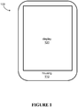
- Figure 1 illustrates one exemplary system for outputting haptic effects in one embodiment of the present disclosure.
- the system shown in Figure 1 is an electronic device 100 for haptic conversion.
- electronic device 100 is a portable handheld phone, such as a smartphone.
- the smartphone 100 includes electronic circuitry for executing applications and allowing a user to interact with the smartphone 100.
- the smartphone 100 includes a housing 110.
- the housing 110 contains electronic components, such as a processor and memory for executing programming code and for interacting with a user.
- the program code stored and executed on the phone or other target device may be used to implement methods of various embodiments of the present disclosure.
- the smartphone 110 also includes a display 120.
- the display 120 may be a touch-sensitive display capable of detecting user interactions with the smartphone 100.
- the smartphone 100 may output effects to alert the user to various interactions.
- the smartphone may execute a gaming application that allows a user to play a game displayed on the display 120 of smartphone 100.
- the game may generate haptic effects that are appropriate for the various events occurring in the game, and the smartphone 100 may output effects that are generated based on the effects output by the game.
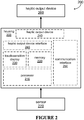
- Figure 2 is a block diagram showing an illustrative system for implementation of one embodiment of the present disclosure.
- Figure 2 illustrates an electronic device 200 for haptic conversion according to one embodiment.
- the electronic device 200 comprises a housing 205, a processor 210, a memory 220, a touch-sensitive display 230, a haptic output device 240, a communication interface 250, and a sensor 270.
- the electronic device 200 may be in communication with haptic output device 260, which may optionally be coupled to or incorporated into some embodiments.
- the electronic device 200 can be any device that is capable of receiving user input e.g., a mobile phone, a tablet, a music player, a wearable device, or a laptop computer. Additionally or alternatively, electronic device 200 may comprise a multifunction controller. For example, a controller for use in a kiosk, ATM, or other computing device. Further, electronic device 200 may comprise a controller for use in a vehicle.
- the processor 210 is in communication with the memory 220, and, in the embodiment shown, both the processor 210 and the memory 220 are disposed within the housing 205.
- the touch-sensitive display 230 which comprises or is in communication with a touch-sensitive surface, is partially disposed within the housing 205 such that at least a portion of the touch-sensitive display 230 is exposed to a user of the electronic device 200. Alternatively, the touch-sensitive display 230 may not be disposed within the housing 205.
- the electronic device 200 may be connected to or otherwise communicate with a touch-sensitive display 230 disposed within a separate housing.
- the housing 205 may comprise two housings that are slidably coupled to each other, pivotably coupled to each other, or releasably coupled to each other.
- the housing 205 may comprise any number of housings.
- the touch-sensitive display 230 is in communication with the processor 210 and is configured to provide signals to the processor 210 and/or the memory 220 and to receive signals from the processor 210 and/or memory 220.
- the processor 210 may comprise a microprocessor, a digital signal processor (DSP), an application-specific integrated circuit (ASIC), field programmable gate arrays (FPGAs), and state machines. Such processors may further comprise programmable electronic devices such as PLCs, programmable interrupt controllers (PICs), programmable logic devices (PLDs), programmable read-only memories (PROMs), electronically programmable read-only memories (EPROMs or EEPROMs), or other similar devices
- PLCs programmable interrupt controllers
- PLDs programmable logic devices
- PROMs programmable read-only memories
- EPROMs or EEPROMs electronically programmable read-only memories
- the memory 220 can comprise any suitable tangible (and non-transitory) computer-readable medium such as RAM, ROM, EEPROM, or the like, that embodies program components that configure operation of the computing device.
- Memory 220 may be configured to store program code or data, or both, for use by the processor 210, which is configured to execute program code stored in memory 220 and to transmit signals to and receive signals from the touch-sensitive display 230.
- the processor 210 is in communication with the communication interface 250 and is configured to receive signals from the communication interface 250 and to output signals to the communication interface 250 to communicate with other components or devices such as one or more electronic devices.
- the processor 210 is in communication with haptic output device 240 and/or haptic output device 260 and is further configured to output signals to cause haptic output device 240 or haptic output device 260, or both, to output one or more haptic effects.
- the processor 210 may be in communication with sensor 270 and configured to receive signals from sensor 270.
- processor 210 may receive one or more signals from sensor 270 corresponding with one or more interactions with the electronic device 200.
- one or more sensor signals may be received by processor 210 from sensor 270 when a user of the electronic device 200 moves or shakes the device 200, such as when playing a video game.
- one or more sensor signals can be received by processor 210 from sensor 270 when a user presses a location on the touch-sensitive display 230 and/or when a user makes a gesture on touch-sensitive display 230.
- Processor 210 may for example receive sensor information from one or more sensors, such as sensor 270, to derive or otherwise determine one or more interactions.
- Interactions can include, but are not limited to, a contact, a series of contacts, a gesture, a contact above a predetermined threshold, a contact below a predetermined threshold, a movement of the device, a vibration, a shake, any other suitable interaction, or a combination thereof.
- Processor 210 may receive one or more sensor signals from one or more input devices integrated into the electronic device 200, connected to the electronic device 200, and/or in communication with the electronic device 200.
- the processor 210 may receive one or more sensor signals from a touch-sensitive surface of the touch-sensitive display 230.
- the processor 210 may receive one or more sensor signals from an input device such as a keyboard, a mouse, a touchpad, a trackball, a microphone, a touch-sensitive surface, a gaming peripheral, such as a Bluetooth-enabled game controller, a button, a trigger, and/or another suitable input device that is integrated into the electronic device 200, connected to the electronic device 200, and/or in communication with the electronic device 200.
- a sensor signal may comprise information such as one or more contacts, locations, pressures, gestures, key presses, and/or other information indicating how a user is interacting with one or more input devices. Numerous other embodiments are disclosed herein and variations are within the scope of this disclosure.
- the processor 210 may then utilize the information it receives from one or more sensors, such as sensor 270, to determine one or more effects to output.
- the first sensor signal may indicate an interaction with electronic device 200 and the processor 210 may use the information in the sensor signal to determine one or more effects that should be output.
- the processor 210 may determine that one or more audio effects, one or more visual effects, and/or one or more haptic effects should be output based at least in part on information received from one or more sensor signals.
- the processor 210 can generate one or more output signals. For example, the processor may determine a haptic effect and generate a haptic signal to be output to haptic output device 240 and/or 260, which then output the haptic effect.
- the haptic signal may be interpreted by a haptic output device interface 245, which in turn can transmit a haptic signal to the haptic output device 240 or haptic output device 260.
- a haptic output device that would typically be present in the platform for which an application was designed i.e., the source haptic output device, may not be available on the target electronic device 200.
- the application may be designed to operate with a LRA (linear resonant actuator) but the target device 200 may instead comprise a piezoelectric actuator.
- the haptic signal may be converted from the source haptic effect to a target haptic effect before the signal is transmitted to the target haptic output device 240 or haptic output device 260 or both.
- the haptic output device interface 245 may access a data store in memory 220 that contains characteristics of haptic output devices 240, 260. The haptic output device interface 245 can then use the characteristics to determine what types of effects haptic output devices 240, 260 are capable of generating and convert the haptic signal from the original source haptic effect to a target effect.
- This target effect may for example comprise an effect that represents the source and at the same time is capable of being output by the target haptic output devices 240, 260. Further details regarding such conversions are provided below.
- Various source haptic output devices and environments may be utilized, such as DualShock (Console, PC), DirectX, Android, IOS, touchsense, wheels, joysticks, steering wheels, and web browsers.
- various target devices including single and multiple-actuator devices, and target environments may be used.
- the following devices and environments may be utilized in various embodiments and/or in any suitable permutation or combination: single or multiple actuator devices, multiple devices (e.g. using a mobile phone and a mobile peripheral), standard haptic actuators (ERM, LRA), high definition actuators (Piezo, EAP, etc.), deformation actuators, friction based touch screens (electrostatic vibration), gaming chairs, and directional devices.
- one player may be utlilizing one environment, such as an iPhone, while a second player is utilizing a second environment, such as an Android OS phone.
- the electronic device 200 may comprise or be in communication with fewer or additional components and/or devices than shown in Figure 2 .
- other user input devices such as a mouse, a keyboard, a camera and/or other input device(s) may be contained within the electronic device 200 or in communication with the electronic device 200.
- electronic device 200 may comprise or otherwise be in communication with one, two, three, or more sensors and/or one, two, three, or more haptic output devices.
- Electronic device 200 need not comprise a communication interface 250.
- Electronic device 200 need not be in communication with haptic output device 260. Numerous other embodiments are disclosed herein and variations are within the scope of this disclosure.
- sensor 270 may be partially or fully disposed within housing 205.
- haptic output device 260 may be disposed within the housing 205 of the electronic device 200.
- the electronic device 200 need not be in communication with haptic output device 260 and need not comprise communication interface 250.
- the electronic device 200 need not comprise a touch-sensitive display 230 or a communication interface 250, but may for example comprise a touch-sensitive surface (e.g., a touchpad) and may be in communication with an external display.
- the electronic device 200 may comprise or be in communication with any number of components, such as in the various embodiments disclosed herein as well as variations that would be apparent to one of skill in the art.
- the electronic device 200 in Figure 2 includes a touch-sensitive display 230 that comprises a touch-sensitive surface.
- a touch-sensitive surface may be overlaid on the touch-sensitive display 230.
- the electronic device 200 may comprise or be in communication with a display and a separate touch-sensitive surface.
- the electronic device 200 may comprise or be in communication with a display and may comprise or be in communication with other user input devices, such as a mouse, a keyboard, buttons, knobs, slider controls, switches, wheels, rollers, other manipulanda, or a combination thereof.
- One or more touch-sensitive surfaces may be included on or disposed within one or more sides of the electronic device 200.
- a touch-sensitive surface may be disposed within or comprise a rear surface of the electronic device 200.
- a first touch-sensitive surface may be disposed within or comprise a rear surface of the electronic device 200 and a second touch-sensitive surface may be disposed within or comprise a side surface of the electronic device 200.
- the touch-sensitive display 230 provides a mechanism for a user to interact with the electronic device 200.
- the touch-sensitive display 230 may detect the location or pressure, or both, of a user's finger in response to a user hovering over, touching, or pressing the touch-sensitive display 230 (all of which may be referred to as a contact in this disclosure).
- a contact can occur through the use of a camera.
- a camera may be used to track movements, such as the viewer's eye movements, as the reader views the content displayed on the display 230 of the electronic device 200.
- Haptic effects may be triggered based at least in part on the viewer's eye movements.
- a haptic effect may be output when a determination is made that the viewer is viewing content at a particular location of the display 230.
- the touch-sensitive display 230 may comprise, be coupled to, be connected with, or otherwise be in communication with one or more sensors that determine the location, pressure, a size of a contact patch, or any of these, of one or more contacts on the touch-sensitive display 230.
- the touch-sensitive display 230 may comprise or be in communication with a mutual capacitance system.
- the touch-sensitive display 230 may comprise or is in communication with an absolute capacitance system.
- the touch-sensitive display 230 may comprise or be in communication with a resistive panel, a capacitive panel, infrared LEDs, photodetectors, image sensors, optical cameras, or a combination thereof.
- the touch-sensitive display 230 may incorporate any suitable technology to determine a contact on a touch-sensitive surface such as, for example, resistive, capacitive, infrared, optical, thermal, dispersive signal, or acoustic pulse technologies, or a combination thereof.
- a determined haptic effect may be modified or otherwise configured based at least in part on interactions and/or other information received from one or more sensors that can be used to determine one or more interactions.
- haptic output devices 240 and 260 are in communication with the processor 210 and are configured to provide one or more haptic effects. For example, when a haptic signal is provided to haptic output device 240, haptic output device 260, or both, by the processor 210, the respective haptic output device(s) 240, 260 output(s) a haptic effect based on the actuation signal.
- the processor 210 may be configured to transmit a haptic signal to haptic output device 240, the haptic signal comprising an analog drive signal.
- the processor 210 may be configured to transmit a command to haptic output device 260, wherein the command includes parameters to be used to generate an appropriate drive signal to cause the haptic output device 260 to output the haptic effect.
- a processor may transmit low-level drive signals to drive a haptic output device to output a haptic effect.
- Such a drive signal may be amplified by an amplifier or may be converted from a digital to an analog signal or from an analog to a digital signal using suitable processors or circuitry to accommodate the particular haptic output device being driven.
- a haptic output device such as haptic output devices 240 or 260, can be any component or collection of components that is capable of outputting one or more haptic effects.
- a haptic output device can be one of various types including, but not limited to, an eccentric rotational mass (ERM) actuator, a linear resonant actuator (LRA), a piezoelectric actuator, a voice coil actuator, an electro-active polymer (EAP) actuator, a memory shape alloy, a pager, a DC motor, an AC motor, a moving magnet actuator, an E-core actuator, a smartgel, an electrostatic actuator, an electrotactile actuator, a deformable surface, an electrostatic friction (ESF) device, an ultrasonic friction (USF) device, or any other haptic output device or collection of components that perform the functions of a haptic output device or that are capable of outputting a haptic effect.
- EEM eccentric rotational mass
- LRA linear resonant actuator
- EAP electro-active polymer
- haptic output devices or different-sized haptic output devices may be used to provide a range of vibrational frequencies, which may be actuated individually or simultaneously.
- Various embodiments may include a single or multiple haptic output devices and may have the same type or a combination of different types of haptic output devices.
- Haptic output device 240 may apply electrostatic friction or attraction, for example by use of an electrostatic surface actuator, to simulate a texture on the surface of touch-sensitive display 230. Similarly, haptic output device 240 may use electrostatic attraction to vary the friction the user feels on the surface of touch-sensitive display 230.
- haptic output device 240 may comprise an electrostatic display or any other device that applies voltages and currents instead of mechanical motion to generate a haptic effect.
- One or more haptic output devices may be directly or indirectly in communication with electronic device 200, such as via wired or wireless communication.
- the electronic device 200 can be placed in a vehicle or may be integrated into a vehicle and one or more haptic output devices 240/260 may be embedded into the vehicle.
- one or more haptic output devices may be embedded in a seat, steering wheel, pedal, etc. of the vehicle.
- the electronic device 200 may have one or more other output devices.
- the electronic device 200 may have a speaker and/or a display.
- the electronic device 200 may have one or more haptic output devices, one or more speakers, and one or more displays. Numerous other embodiments are disclosed herein and variations are within the scope of this disclosure.
- one or more haptic effects may be produced in any number of ways or in a combination of ways.
- one or more vibrations may be used to produce a haptic effect, such as by rotating an eccentric mass or by linearly oscillating a mass.
- the haptic effect may be configured to impart a vibration to the entire electronic device or to only one surface or a limited part of the electronic device. Friction between two or more components or friction between at least one component and at least one contact may be used to produce a haptic effect, such as by applying a brake to a moving component, such as to provide resistance to movement of a component or to provide a torque.
- many devices utilize some type of actuator and/or other haptic output device.
- haptic output devices used for this purpose include an electromagnetic actuator such as an Eccentric Rotating Mass (“ERM”) in which an eccentric mass is moved by a motor, a Linear Resonant Actuator (“LRA”) in which a mass attached to a spring is driven back and forth, or a “smart material” such as piezoelectric, electro-active polymers or shape memory alloys.
- EEM Eccentric Rotating Mass
- LRA Linear Resonant Actuator
- a “smart material” such as piezoelectric, electro-active polymers or shape memory alloys.
- Deformation of one or more components can be used to produce a haptic effect.
- one or more haptic effects may be output to change the shape of a surface or a coefficient of friction of a surface.
- One or more haptic effects may be produced by creating electrostatic forces and/or ultrasonic forces that are used to change friction on a surface.
- An array of transparent deforming elements may be used to produce a haptic effect, such as one or more areas comprising a smartgel.
- Haptic output devices also broadly include non-mechanical or non-vibratory devices such as those that use electrostatic friction (ESF), ultrasonic surface friction (USF), or those that induce acoustic radiation pressure with an ultrasonic haptic transducer, or those that use a haptic substrate and a flexible or deformable surface, or those that provide projected haptic output such as a puff of air using an air jet, and so on.
- a haptic effect may be a kinesthetic effect.
- U.S. Patent Application Publication No. 2011-0264491 A1 describes ways that one or more haptic effects can be produced and describes various haptic output devices.
- the communication interface 250 is in communication with the processor 210 and provides wired or wireless communications, from the electronic device 200 to other components or other devices, and/or vice versa.
- the communication interface 250 may provide wireless communications between the electronic device 200 and a wireless sensor or a wireless actuation device.
- the communication interface 250 may provide communications to one or more other devices, such as another electronic device 200, to allow users to interact with each other at their respective devices.
- the communication interface 250 can be any component or collection of components that enables the (for example multi-pressure touch-sensitive input) electronic device 200 to communicate with another component or device.
- the communication interface 250 may comprise a PCI network adapter, a USB network adapter, or an Ethernet adapter.
- the communication interface 250 may communicate using wireless Ethernet, including 802.11 a, g, b, or n standards.
- the communication interface 250 may communicate using Radio Frequency (RF), Bluetooth, CDMA, TDMA, FDMA, GSM, WiFi, satellite, or other cellular or wireless technology.
- the communication interface 250 may communicate through a wired connection and may be in communication with one or more networks, such as Ethernet, token ring, USB, FireWire 1394, fiber optic, etc.
- Electronic device 200 may comprise a single communication interface 250. Alternatively, electronic device 200 may comprise two, three, four, or more communication interfaces. Thus, electronic device 200 may be able to communicate with one or more components and/or devices through one or more communication interfaces. Alternatively electronic device 200 may not comprise a communication interface 250.
- Figure 2 depicts a single sensor 270. However, multiple sensors can be used. Additionally, a sensor may be housed in the same component as the other components of the electronic device 200 or in a separate component. For example, the processor 210, memory 220, and sensor 270 may all be comprised in an electronic device 200, such as a portable music player, a portable telephone, and/or a wearable device. Additionally or alternatively, a sensor may be placed in a component separate from another component that houses the memory and/or processor. For instance, a wearable sensor may be in communication with the processor and memory or an electronic device via a wired or wireless connection.
- the electronic device 200 may comprise two or more housing components, such as in a clamshell arrangement or in a slidable arrangement.
- electronic device 200 may comprise a clamshell configuration with a touch-sensitive display disposed in each of the portions of the clamshell.
- the display 230 may or may not comprise a touch-sensitive surface.
- One or more touch-sensitive surfaces may have a flexible touch-sensitive surface.
- One or more touch-sensitive surfaces may be rigid.
- the electronic device 200 may comprise both flexible and rigid touch-sensitive surfaces.
- the housing 205 of the electronic device 200 shown in Figure 2 provides protection for at least some of the components of electronic device 200.
- the housing 205 may be a plastic casing that protects the processor 210 and memory 220 from foreign articles such as rain, dirt, or dust.
- the housing 205 may protect the components in the housing 205 from damage if the electronic device 200 is dropped by a user.
- the housing 205 can be made of any suitable material including but not limited to plastics, rubbers, or metals.
- Various embodiments may comprise different types of housings or a plurality of housings.
- electronic device 200 may be a portable device, handheld device, toy, gaming console, handheld video game system, gamepad, game controller, desktop computer, portable multifunction device such as a cell phone, smartphone, personal digital assistant (PDA), eReader, portable reading device, handheld reading device, laptop, tablet computer, digital music player, remote control, medical instrument, etc.
- the electronic device 200 may be embedded in another device such as a vehicle, wrist watch, other jewelry, arm band, gloves, etc.
- the electronic device 200 may be wearable.
- the electronic device 200 may be embedded in another device such as, for example, the console of a car or a steering wheel. Numerous other embodiments are disclosed herein and variations are within the scope of this disclosure.
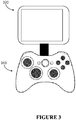
- Figure 3 illustrates another exemplary system for outputting haptic effects according to one embodiment of the present disclosure.
- the embodiment shown in Figure 3 comprises a mobile device 320, such as a mobile telephone (e.g., a smartphone).
- the mobile telephone 320 may include various components as shown illustrated in Figure 2 .
- the mobile phone 320 is in coupled to a mobile game controller 340 using a wired or wireless connection (e.g., wi-fi, Bluetooth, or other wireless connection known in the art).
- a wired or wireless connection e.g., wi-fi, Bluetooth, or other wireless connection known in the art.
- the game controller 340 includes controls, such as buttons and joysticks for use in controlling a game or other software executing on the mobile telephone 320.
- the game controller may include one or more haptic output devices, such as those shown in Figure 2 .
- the haptic output device is contained within the mobile telephone 320, and effects are transmitted (e.g. mechanically) to the game controller 340 via the mobile telephone 320.
- Various other embodiments are also possible.
- FIG 4 is a block diagram showing the functional components of a system for implementation of one embodiment of the present disclosure.
- a system 400 includes a device 405.
- the device 405 is in communication with a sensor 410, such as those described above in relation to Figure 2 .
- the sensor 410 detects user interactions and provides information regarding those interactions to the device 405 through a communication interface 420.
- the communication interface 420 provides the user interactions to a haptic effect generator 430.
- the haptic effect generator 430 may be, for example, a game program for executing a game running on the device 405.
- the haptic effect generator 430 may be designed for devices that include different haptic output device capabilities (different source haptic output devices) than the haptic output devices/capabilities available with device 405.
- the haptic effect generator 430 is a game program
- the haptic effect generator may for example be designed to output haptic effects to a game controller having two similarly-sized eccentric rotating mass motors designed to produce vibrations in a game controller.
- the device 405 may include, for example, a single haptic output device 480.
- the single haptic output device 480 may be of a different type than that for which the game was originally designed.
- the device 405 in Figure 4 also comprises a haptic conversion layer 440.
- the haptic conversion layer 440 may include one or more hardware and software components for converting a haptic effect from one intended for a source haptic output device to one capable of being output by the target haptic output device 480, and/or for converting the haptic effect so that it more closely reproduces the intended (source) haptic effect using the target haptic output device 480.
- the haptic conversion layer 440 may include one or more data stores for determining one or more characteristics of haptic output device 480.
- the characteristics may include, for example, the number and types of haptic output devices in communication with, contained within, or coupled to the device 405, as well as specific operating characteristics of those haptic output devices (e.g., time to accelerate, time to decelerate, maximum or minimum available power, maximum or minimum available operating frequency, etc.).
- the haptic conversion layer 440 can utilize the characteristics to determine how to represent the haptic effect as produced by the source haptic output device when provided by the target haptic output device 480.
- the haptic conversion layer 440 may comprise an application programming interface ("API") and may be in communication with or utilize one or more existing API's to implement the method illustrated in Figure 4 .
- the haptic conversion layer 440 may also be implemented as a separate chip incorporated into the target device or into an interface between the target device and a peripheral.
- the haptic conversion layer 440 may include a data store for storing user preferences. The user may be able to "tune" the effects generated on the target device by, for example, increasing or decreasing the magnitude with which effects are converted.
- the signal that is generated by the haptic conversion layer 440 is then provided to the haptic output device interface 460.
- the haptic output device interface 460 then provides an appropriate signal to the haptic output device 460.
- the haptic conversion layer 440 may provide a high-level command to the haptic output device interface 460.
- the haptic output device interface 460 then generates a signal that can be sent to the haptic output device 480 to cause a haptic effect to be generated. Numerous other embodiments are disclosed herein and variations are within the scope of this disclosure.
- Embodiments of the present disclosure may implement a conversion layer that takes haptic commands from various different sources and maps them according to the capabilities of the current haptic device.
- the conversion layer may provide the ability to create haptics according to the capabilities of the target device but using different sources of haptic calls, such as a dual shock controller or touch-sensitive device.
- a device according to the present disclosure may allow a user controlling a console game with a mobile device to feel the game's haptic output without the game developer changing the original dual-actuator effect code.
- Figure 5 illustrates a flow chart directed to a method 500 of haptic conversion in accordance with one embodiment of the present disclosure.
- the steps in Figure 5 may be implemented in program code executed by a processor, for example, the processor in a general purpose computer, mobile device, or server. These steps may be implemented by a group of processors.
- the steps shown in Figure 5 may be performed in a different order. Alternatively, one or more of the steps shown in Figure 5 may be skipped, or additional steps not shown in Figure 5 may be performed.
- the steps below are described with reference to components described above with regard to device 200 shown in Figure 2 .
- the process 500 begins when a processor 210 receives the first sensor signal(s) 510.
- the processor 210 may receive a sensor signal indicating that a user has interacted with a control displayed on a touch-sensitive display 230.
- the processor 210 next determines a characteristic of a target user interface device 520. For example, the processor 210 may determine that the target user interface device includes a single haptic output device 240. The processor may further determine the type of haptic output device 240. For example, the processor may determine that the haptic output device 240 is a vibrating motor. During initialization, or at some other point, the processor 210 may perform testing to determine what types of haptic effects the target haptic output device 240 is capable of performing.
- the processor 210 may be configured to access a data store, e.g., memory 220 comprising a map of the duration, magnitude and envelope of the source and target motors.
- the processor 210 may also convert the haptic effect from an effect configured to operate with a dual actuator source to a haptic effect configured to operate with a single actuator target. For instance, the duration and magnitude being sent to two actuators may be averaged and then sent to the single actuator in order to provide an effect.
- One or more of the target actuators may be the same or similar to one or more of the source actuators. In such a case, the mapping between any two actuators may be a simple, direct mapping.
- the target actuator may have a greater haptic capability than the source actuator.
- an augmented mapping could occur.
- a dual ERM DualShock
- pulsing vibration mapping parameters could be used to simulate both the large and small ERM motors (or average that feeling if both are playing in the source effect)
- additional audible range frequency mapping could be applied for the piezo mapping that is not possible with the slower ERM actuators.
- the source haptic effect could have additional directional haptic mapping applied to the target actuation.
- an augmented haptic mapping having vibration as well as temperature parameters would be allowed for, e.g., warmer for large motor mappings and cooler for smaller motor mappings.
- a source vibration command is modified for a target deformation actuator. For instance, a high frequency vibration may be converted to a small motion haptic effect. And a low frequency vibration is converted to a large motion effect.
- a design tool is used to determine effects on a source platform, such as a PC, and map those effects to a target platform, such as Android.
- a designer of a user interface is able to design haptic effects for a program for use on a particular device. Subsequently, if the user interface is executed on a different device platform than the one for which the effects were designed, then the effects may be automatically converted to the new platform without the need for the designer to take additional steps to enable the appropriate effects on the new platform. For instance, a game designer is able to design a game for play on a gamepad for a PC, and upon execution of the same game on a mobile phone, the haptic effects are automatically converted so that the effects on the mobile phone correspond to the effects that the designer originally specified.
- the processor 210 next determines a source haptic effect 530.
- the source haptic effect may comprise a haptic effect generated by an application prior to conversion.
- the designer of a game may associate a certain haptic effect with a particular occurrence in a game. For instance, if an explosion occurs, the game may be designed to output a high-magnitude, relatively long duration vibration through both eccentric rotating mass motors in a game controller.
- application developer may have designed the haptic effect to be output using specific types of haptic output devices.
- the user interface device 200 may not comprise these types of haptic output devices.
- the processor 210 next converts the source haptic effect to a target haptic effect 540.
- the conversion may be based on the one or more characteristics of the target user interface device 200 determined at 520.
- the conversion will for example attempt a conversion that represents the source haptic effect on the target user interface device given the characteristic(s) of the target user interface device 200.
- This conversion may be configured to compensate for factors such as the number of haptic output devices, the type of haptic output devices, the available bandwidth of haptic output devices, the available power of the haptic output devices, and factors associated with the source haptic effect.
- a processor 210 maps source effects for a source device having M source actuators to destination effects for a destination or target device having N destination actuators. If each source effect address only one source actuator and each destination effect address only one destination actuator, the processor 210 may perform the following steps: for each source effect, map the source effect to a destination effect addressing the destination actuator that can reproduce the source effect given source actuator performance characteristics and destination actuator performance characteristics over the dynamic range of the source effect. For instance, if a source effect is a low-frequency effect, and the target includes a destination actuator that is capable of outputting the same or similar effect as the source actuator, the processor maps the source effect to a destination effect on that particular target actuator.
- mapping from M to N actuators directional spatial information may be preserved. For example, if a right to left directional haptic effect is used as a source haptic effect, the same right to left directional effect may be preserved for the target effect even though the target device may have less or more actuators.
- the processor 210 then generates a haptic signal associated with the target effect 560. This signal can then be output to one or more haptic output devices 240 to allow the user to experience the effect. While the target device is described as having a single haptic output device 240, multiple haptic output devices may be present. And the haptic signal that is generated may be generated for one, some, or all of the haptic output devices present on the target user interface device 200.
- configurations may be described as a process that is depicted as a flow diagram or block diagram. Although each may describe the operations as a sequential process, many of the operations can be performed in parallel or concurrently. In addition, the order of the operations may be rearranged. A process may have additional steps not included in the figure.
- examples of the methods may be implemented by hardware, software, firmware, middleware, microcode, hardware description languages, or any combination thereof. When implemented in software, firmware, middleware, or microcode, the program code or code segments to perform the necessary tasks may be stored in a non-transitory computer-readable medium such as a storage medium. Processors may perform the described tasks.
- a computer may comprise a processor or processors.
- the processor comprises or has access to a computer-readable medium, such as a random access memory (RAM) coupled to the processor.
- the processor may execute computer-executable program instructions stored in memory, such as executing one or more computer programs including a sensor sampling routine, selection routines, and other routines to perform the methods described above.
- Such processors may comprise a microprocessor, a digital signal processor (DSP), an application-specific integrated circuit (ASIC), field programmable gate arrays (FPGAs), and state machines.
- Such processors may further comprise programmable electronic devices such as PLCs, programmable interrupt controllers (PICs), programmable logic devices (PLDs), programmable read-only memories (PROMs), electronically programmable read-only memories (EPROMs or EEPROMs), or other similar devices.
- Such processors may comprise, or may be in communication with, media, for example tangible computer-readable media, that may store instructions that, when executed by the processor, can cause the processor to perform the steps described herein as carried out, or assisted, by a processor.
- Examples of computer-readable media may comprise, but are not limited to, all electronic, optical, magnetic, or other storage devices capable of providing a processor, such as the processor in a web server, with computer-readable instructions.
- Other examples of media comprise, but are not limited to, a floppy disk, CD-ROM, magnetic disk, memory chip, ROM, RAM, ASIC, configured processor, all optical media, all magnetic tape or other magnetic media, or any other medium from which a computer processor can read.
- various other devices may include computer-readable media, such as a router, private or public network, or other transmission device.
- the processor, and the processing, described may be in one or more structures, and may be dispersed through one or more structures.
- the processor may comprise code for carrying out one or more of the methods (or parts of methods) described herein.
Claims (14)
- Ein Verfahren (500) umfassend:(530) Bestimmen eines Quell-Haptikeffekts, der einer Quellbenutzerschnittstellenvorrichtung mit einer Quell-Haptik-Ausgabevorrichtung zugeordnet ist, die konfiguriert ist, um den Quell-Haptikeffekt auszugeben;dadurch gekennzeichnet, dass der Quell-Haptikeffekt durch eine Zielbenutzerschnittstellenvorrichtung (100, 200, 320, 340), die ein Zielgerät für die haptische Ausgabe (240, 260) aufweist, bestimmt wird, wobei das Verfahren weiterhin die Schritte umfasst:(520) Bestimmen einer Eigenschaft der Zielbenutzerschnittstellenvorrichtung;(540) Umwandeln des Quell-Haptikeffekts in einen Ziel-Haptikeffekt, wobei die Umwandlung zumindest teilweise auf der Charakteristik der Zielbenutzerschnittstellenvorrichtung basiert; und(560) Erzeugen eines dem Ziel-Haptikeffekt zugeordneten Haptiksignals, wobei das Haptiksignal konfiguriert ist, um das Zielgerät für die haptische Ausgabe zu veranlassen, den Ziel-Haptikeffekt auszugeben.
- Das Verfahren (500) gemäß Anspruch 1, wobei das (520) Bestimmen der Charakteristik der Zielbenutzerschnittstellenvorrichtung das Bestimmen eines haptischen Ausgabegerätetyps und/oder das Identifizieren eines haptischen Ausgabegeräts (240, 260) in dem Zielmobilgerät (100, 200, 320) umfasst.
- Das Verfahren (500) gemäß Anspruch 1 oder 2, wobei das (520) Bestimmen der Charakteristik der Zielbenutzerschnittstellenvorrichtung das Erfassen der Zahl und der Typen von haptischen Ausgabegeräten umfasst, die in Kommunikation mit der Zielbenutzerschnittstellenvorrichtung stehen, darin enthalten sind oder mit dieser gekoppelt sind.
- Das Verfahren (500) gemäß Anspruch 3, wobei:das Zielgerät für die haptische Ausgabe (240, 260) einen einzelnen Motor umfasst, der zum Ausgeben einer Vibration konfiguriert ist, undwobei das Umwandeln des Quell-Haptikeffekts in den Ziel-Haptikeffekt das Interpretieren einer Darstellung einer Zwei-Motoren-Vibration umfasst, die vom Zielgerät für die haptische Ausgabe ausgegeben werden kann.
- Das Verfahren (500) gemäß irgendeinem der vorhergehenden Ansprüche, ferner umfassend das Veranlassen, dass das Zielgerät für die haptische Ausgabe (240, 260) den Quell-Haptikeffekt ausgibt.
- Das Verfahren (500) gemäß irgendeinem der vorhergehenden Ansprüche, wobei der Quell-Haptikeffekt durch einen Haptikeffektgenerator (430) bestimmt wird und wobei der Quell-Haptikeffekt durch eine oder mehrere Hardware- und Softwarekomponenten (440) in den Ziel-Haptikeffekt umgewandelt wird.
- Das Verfahren (500) gemäß irgendeinem der vorhergehenden Ansprüche, wobei die Quellbenutzerschnittstellenvorrichtung eine Spielekonsolensteuerung umfasst und/oder wobei die Zielbenutzerschnittstellenvorrichtung ein Mobiltelefon umfasst.
- Ein System (100, 200, 320) umfassend:eine Zielbenutzerschnittstellenvorrichtung (100, 200, 320, 340) mit einem Zielgerät für die haptische Ausgabe (240, 260); undeinen Prozessor (210), der mit dem Zielgerät für die haptische Ausgabe gekoppelt und konfiguriert ist, zum:Erzeugen (560) eines dem Ziel-Haptikeffekt zugeordneten Haptiksignals, wobei das Haptiksignal konfiguriert ist, um das Zielgerät für die haptische Ausgabe zu veranlassen, den Ziel-Haptikeffekt auszugeben; undund Übertragen des haptischen Signals an das Zielgerät für die haptische Ausgabe;dadurch gekennzeichnet, dass der Prozessor (210) weiterhin konfiguriert ist, zum:Bestimmen (530) eines eines Quell-Haptikeffekts, der einer Quellbenutzerschnittstellenvorrichtung mit einer Quell-Haptik-Ausgabevorrichtung zugeordnet ist, die konfiguriert ist, um den Quell-Haptikeffekt auszugeben;Bestimmen (520) einer Eigenschaft einer Zielbenutzerschnittstellenvorrichtung; undUmwandeln (540) des Quell-Haptikeffekts in einen Ziel-Haptikeffekt, wobei die Umwandlung zumindest teilweise auf der Charakteristik der Zielbenutzerschnittstellenvorrichtung basiert.
- Das System (100, 200, 320) gemäß Anspruch 8, wobei das Bestimmen der Charakteristik der Zielbenutzerschnittstellenvorrichtung das Bestimmen eines haptischen Ausgabegerätetyps und/oder das Identifizieren eines haptischen Ausgabegeräts (240, 260) in dem Zielmobilgerät umfasst.
- Das System (100, 200, 320) gemäß Anspruch 9 oder 10, wobei das Bestimmen der Charakteristik der Zielbenutzerschnittstellenvorrichtung das Erfassen der Zahl und der Typen von haptischen Ausgabegeräten umfasst, die in Kommunikation mit der Zielbenutzerschnittstellenvorrichtung stehen, darin enthalten sind oder mit dieser gekoppelt sind.
- Das System (100, 200, 320) gemäß Anspruch 10, wobei:das Zielgerät für die haptische Ausgabe (240, 260) einen einzelnen Motor umfasst, der zum Ausgeben einer Vibration konfiguriert ist, undwobei das Umwandeln des Quell-Haptikeffekts in den Ziel-Haptikeffekt das Interpretieren einer Darstellung einer Zwei-Motoren-Vibration umfasst, die vom Zielgerät für die haptische Ausgabe ausgegeben werden kann.
- Das System (100, 200, 320) gemäß irgendeinem der Ansprüche 8 bis 11, wobei die Quellbenutzerschnittstellenvorrichtung eine Spielkonsolensteuerung umfasst und/oder wobei die Zielbenutzerschnittstellenvorrichtung ein Mobiltelefon umfasst.
- Das System gemäß irgendeinem der Ansprüche 8 bis 12, wobei der Quell-Haptikeffekt durch einen Haptikeffektgenerator (430) bestimmt wird und wobei der Quell-Haptikeffekt durch eine oder mehrere Hardware- und Softwarekomponenten (440) in den Ziel-Haptikeffekt umgewandelt wird.
- Ein Nichtflüchtiges computerlesbares Medium mit Programmcode, der, wenn er von einem Prozessor ausgeführt wird, konfiguriert ist, um den Prozessor zu veranlassen, das Verfahren gemäß einem der Ansprüche 1 bis 7 auszuführen.
Priority Applications (1)
| Application Number | Priority Date | Filing Date | Title |
|---|---|---|---|
| EP19177222.7A EP3553633A1 (de) | 2013-09-10 | 2014-09-08 | Systeme und verfahren zur durchführung von haptischer umwandlung |
Applications Claiming Priority (1)
| Application Number | Priority Date | Filing Date | Title |
|---|---|---|---|
| US14/022,694 US9558637B2 (en) | 2013-09-10 | 2013-09-10 | Systems and methods for performing haptic conversion |
Related Child Applications (2)
| Application Number | Title | Priority Date | Filing Date |
|---|---|---|---|
| EP19177222.7A Division-Into EP3553633A1 (de) | 2013-09-10 | 2014-09-08 | Systeme und verfahren zur durchführung von haptischer umwandlung |
| EP19177222.7A Division EP3553633A1 (de) | 2013-09-10 | 2014-09-08 | Systeme und verfahren zur durchführung von haptischer umwandlung |
Publications (2)
| Publication Number | Publication Date |
|---|---|
| EP2846230A1 EP2846230A1 (de) | 2015-03-11 |
| EP2846230B1 true EP2846230B1 (de) | 2019-08-07 |
Family
ID=51542150
Family Applications (2)
| Application Number | Title | Priority Date | Filing Date |
|---|---|---|---|
| EP19177222.7A Withdrawn EP3553633A1 (de) | 2013-09-10 | 2014-09-08 | Systeme und verfahren zur durchführung von haptischer umwandlung |
| EP14184000.9A Active EP2846230B1 (de) | 2013-09-10 | 2014-09-08 | Systeme und Verfahren zur Durchführung von haptischer Umwandlung |
Family Applications Before (1)
| Application Number | Title | Priority Date | Filing Date |
|---|---|---|---|
| EP19177222.7A Withdrawn EP3553633A1 (de) | 2013-09-10 | 2014-09-08 | Systeme und verfahren zur durchführung von haptischer umwandlung |
Country Status (5)
| Country | Link |
|---|---|
| US (3) | US9558637B2 (de) |
| EP (2) | EP3553633A1 (de) |
| JP (2) | JP6478535B2 (de) |
| KR (1) | KR102224434B1 (de) |
| CN (2) | CN110109533A (de) |
Families Citing this family (30)
| Publication number | Priority date | Publication date | Assignee | Title |
|---|---|---|---|---|
| US9558637B2 (en) | 2013-09-10 | 2017-01-31 | Immersion Corporation | Systems and methods for performing haptic conversion |
| US10067566B2 (en) | 2014-03-19 | 2018-09-04 | Immersion Corporation | Systems and methods for a shared haptic experience |
| EP3189395A2 (de) | 2014-09-02 | 2017-07-12 | Apple Inc. | Semantischer rahmen für variable haptische ausgabe |
| US9774929B2 (en) * | 2014-09-22 | 2017-09-26 | Itron, Inc. | Infrared proximity sensor control of devices |
| US9846484B2 (en) * | 2014-12-04 | 2017-12-19 | Immersion Corporation | Systems and methods for controlling haptic signals |
| US9919208B2 (en) | 2014-12-11 | 2018-03-20 | Immersion Corporation | Video gameplay haptics |
| US20160321880A1 (en) * | 2015-04-28 | 2016-11-03 | Immersion Corporation | Systems And Methods For Tactile Guidance |
| US9645647B2 (en) * | 2015-05-13 | 2017-05-09 | Immersion Corporation | Systems and methods for haptic feedback for modular devices |
| US10200332B2 (en) | 2015-12-14 | 2019-02-05 | Immersion Corporation | Delivery of haptics to select recipients of a message |
| US10102722B2 (en) | 2015-12-18 | 2018-10-16 | Immersion Corporation | Wearable article having an actuator that performs non-haptic and haptic operations |
| US10585480B1 (en) | 2016-05-10 | 2020-03-10 | Apple Inc. | Electronic device with an input device having a haptic engine |
| DK179823B1 (en) | 2016-06-12 | 2019-07-12 | Apple Inc. | DEVICES, METHODS, AND GRAPHICAL USER INTERFACES FOR PROVIDING HAPTIC FEEDBACK |
| DK179657B1 (en) | 2016-06-12 | 2019-03-13 | Apple Inc. | Devices, methods and graphical user interfaces for providing haptic feedback |
| EP3291054B8 (de) * | 2016-09-06 | 2019-07-24 | Apple Inc. | Vorrichtungen, verfahren und grafische benutzeroberflächen zur haptischen mischung |
| DK179278B1 (en) | 2016-09-06 | 2018-03-26 | Apple Inc | Devices, methods and graphical user interfaces for haptic mixing |
| DK201670720A1 (en) | 2016-09-06 | 2018-03-26 | Apple Inc | Devices, Methods, and Graphical User Interfaces for Generating Tactile Outputs |
| US10254734B2 (en) * | 2016-11-21 | 2019-04-09 | Avaya Inc. | Testing user interface functionality through actuation by a piezoelectric grid |
| DK201770372A1 (en) | 2017-05-16 | 2019-01-08 | Apple Inc. | TACTILE FEEDBACK FOR LOCKED DEVICE USER INTERFACES |
| US11054932B2 (en) | 2017-09-06 | 2021-07-06 | Apple Inc. | Electronic device having a touch sensor, force sensor, and haptic actuator in an integrated module |
| US10216231B1 (en) * | 2018-02-20 | 2019-02-26 | Nvf Tech Ltd | Moving magnet actuator for haptic alerts |
| US10936071B2 (en) | 2018-08-30 | 2021-03-02 | Apple Inc. | Wearable electronic device with haptic rotatable input |
| US10966007B1 (en) | 2018-09-25 | 2021-03-30 | Apple Inc. | Haptic output system |
| KR20200126158A (ko) * | 2019-04-29 | 2020-11-06 | 삼성전자주식회사 | 사운드를 출력하는 액추에이터를 포함하는 전자 장치와 이의 동작 방법 |
| WO2020258319A1 (zh) * | 2019-06-28 | 2020-12-30 | 瑞声声学科技(深圳)有限公司 | 触感信号生成方法、装置和计算机设备 |
| US11358054B2 (en) * | 2020-02-18 | 2022-06-14 | Electronic Arts Inc. | Systems and methods for transcribing user interface elements of a game application into haptic feedback |
| US11024135B1 (en) | 2020-06-17 | 2021-06-01 | Apple Inc. | Portable electronic device having a haptic button assembly |
| CN112121411A (zh) * | 2020-09-18 | 2020-12-25 | 腾讯科技(深圳)有限公司 | 震动控制方法、装置、电子设备和计算机可读存储介质 |
| CN112416477B (zh) * | 2020-11-27 | 2022-04-26 | 瑞声新能源发展(常州)有限公司科教城分公司 | 信号转换方法、装置、计算机设备和存储介质 |
| JP7340556B2 (ja) * | 2021-02-26 | 2023-09-07 | 任天堂株式会社 | 振動制御システム |
| GB2615548A (en) * | 2022-02-10 | 2023-08-16 | Sony Interactive Entertainment Inc | Methods and systems for providing haptic feedback |
Family Cites Families (20)
| Publication number | Priority date | Publication date | Assignee | Title |
|---|---|---|---|---|
| TW389918B (en) | 1997-08-24 | 2000-05-11 | Sony Computer Entertainment Inc | Game apparatus, game machine manipulation device, game system and interactive communication method for game apparatus |
| JPH1157212A (ja) * | 1997-08-24 | 1999-03-02 | Sony Computer Entertainment:Kk | ゲーム装置、ゲーム機用操作装置、ゲームシステム及びゲーム装置の双方向通信方法 |
| DE20080209U1 (de) * | 1999-09-28 | 2001-08-09 | Immersion Corp | Steuerung von haptischen Empfindungen für Schnittstellenvorrichtungen mit Vibrotaktiler Rückkopplung |
| JP5275025B2 (ja) * | 2005-06-27 | 2013-08-28 | コアクティヴ・ドライヴ・コーポレイション | 触覚フィードバック用の同期式振動装置 |
| US7920694B2 (en) | 2006-02-03 | 2011-04-05 | Immersion Corporation | Generation of consistent haptic effects |
| US7938009B2 (en) * | 2006-02-03 | 2011-05-10 | Immersion Corporation | Haptic device testing |
| US8701026B2 (en) * | 2006-03-07 | 2014-04-15 | Goma Systems Corporation | User interface |
| CN104656900A (zh) * | 2006-09-13 | 2015-05-27 | 意美森公司 | 用于游戏厅游戏触觉的系统和方法 |
| US20090181724A1 (en) * | 2008-01-14 | 2009-07-16 | Sony Ericsson Mobile Communications Ab | Touch sensitive display with ultrasonic vibrations for tactile feedback |
| US20090295739A1 (en) * | 2008-05-27 | 2009-12-03 | Wes Albert Nagara | Haptic tactile precision selection |
| US8390594B2 (en) * | 2009-08-18 | 2013-03-05 | Immersion Corporation | Haptic feedback using composite piezoelectric actuator |
| CN105824413B (zh) | 2010-04-23 | 2019-05-21 | 意美森公司 | 用于提供触觉效果的系统和方法 |
| KR100986681B1 (ko) | 2010-05-06 | 2010-10-08 | (주)이미지스테크놀로지 | 촉각 발생을 위한 다중 액튜에이터 구동 제어장치 |
| US20110309918A1 (en) | 2010-06-17 | 2011-12-22 | Immersion Corporation | System and Method for Compensating for Aging Haptic Actuators |
| US8710965B2 (en) * | 2010-09-22 | 2014-04-29 | At&T Intellectual Property I, L.P. | Devices, systems, and methods for tactile feedback and input |
| CA2719659C (en) * | 2010-11-05 | 2012-02-07 | Ibm Canada Limited - Ibm Canada Limitee | Haptic device with multitouch display |
| TWI530818B (zh) * | 2011-01-20 | 2016-04-21 | 宏達國際電子股份有限公司 | 具有觸覺回饋之電子裝置及提供觸覺回饋之方法 |
| JP5738052B2 (ja) | 2011-04-18 | 2015-06-17 | 京セラ株式会社 | 携帯情報端末、触覚サーバ、触覚サービスシステム、及び通信方法 |
| US20140098038A1 (en) * | 2012-10-10 | 2014-04-10 | Microsoft Corporation | Multi-function configurable haptic device |
| US9558637B2 (en) | 2013-09-10 | 2017-01-31 | Immersion Corporation | Systems and methods for performing haptic conversion |
-
2013
- 2013-09-10 US US14/022,694 patent/US9558637B2/en active Active
-
2014
- 2014-09-05 KR KR1020140118712A patent/KR102224434B1/ko active IP Right Grant
- 2014-09-08 EP EP19177222.7A patent/EP3553633A1/de not_active Withdrawn
- 2014-09-08 EP EP14184000.9A patent/EP2846230B1/de active Active
- 2014-09-09 JP JP2014183117A patent/JP6478535B2/ja active Active
- 2014-09-10 CN CN201811493050.2A patent/CN110109533A/zh active Pending
- 2014-09-10 CN CN201410458057.6A patent/CN104423595B/zh active Active
-
2016
- 2016-12-20 US US15/385,258 patent/US9878239B2/en active Active
-
2017
- 2017-12-05 US US15/831,970 patent/US20180093178A1/en not_active Abandoned
-
2019
- 2019-02-05 JP JP2019018840A patent/JP2019114270A/ja not_active Withdrawn
Non-Patent Citations (1)
| Title |
|---|
| None * |
Also Published As
| Publication number | Publication date |
|---|---|
| JP6478535B2 (ja) | 2019-03-06 |
| CN110109533A (zh) | 2019-08-09 |
| US20180093178A1 (en) | 2018-04-05 |
| JP2015056183A (ja) | 2015-03-23 |
| US20150072789A1 (en) | 2015-03-12 |
| CN104423595A (zh) | 2015-03-18 |
| KR102224434B1 (ko) | 2021-03-08 |
| US9878239B2 (en) | 2018-01-30 |
| JP2019114270A (ja) | 2019-07-11 |
| EP2846230A1 (de) | 2015-03-11 |
| US9558637B2 (en) | 2017-01-31 |
| US20170100666A1 (en) | 2017-04-13 |
| EP3553633A1 (de) | 2019-10-16 |
| KR20150029581A (ko) | 2015-03-18 |
| CN104423595B (zh) | 2019-01-01 |
Similar Documents
| Publication | Publication Date | Title |
|---|---|---|
| US9878239B2 (en) | Systems and methods for performing haptic conversion | |
| EP3093736B1 (de) | Systeme und verfahren für haptisches feedback für modulare vorrichtungen | |
| US10248210B2 (en) | Systems and methods for haptically-enabled conformed and multifaceted displays | |
| US10152131B2 (en) | Systems and methods for multi-pressure interaction on touch-sensitive surfaces | |
| CN104375633B (zh) | 用于触觉摆弄的系统和方法 | |
| EP2701037B1 (de) | Kontextabhängiges haptisches bestätigungssystem | |
| JP6612522B2 (ja) | 没入型環境における非コロケートな触覚キュー | |
| KR20170120145A (ko) | 상황 감응식 햅틱 통지 프레임워크들을 제공하기 위한 시스템들 및 방법들 | |
| JP2016095847A (ja) | ハプティックコントローラ | |
| CN103513767A (zh) | 触觉反馈控制系统 | |
| US10474238B2 (en) | Systems and methods for virtual affective touch | |
| EP3333674A1 (de) | Systeme und verfahren für nachgiebigkeitssimulation mit haptik | |
| EP3455704A1 (de) | Multimodale haptische effekte | |
| KR20150079445A (ko) | 표면 피쳐를 생성하기 위해 주름형 테셀레이션을 이용하기 위한 장치, 시스템, 및 방법 | |
| US20200387246A1 (en) | Systems and methods for particle jamming haptic feedback | |
| EP3367216A1 (de) | Systeme und verfahren zur virtuellen affektiven berührung | |
| US20200286298A1 (en) | Systems and methods for a user interaction proxy |
Legal Events
| Date | Code | Title | Description |
|---|---|---|---|
| 17P | Request for examination filed |
Effective date: 20140908 |
|
| AK | Designated contracting states |
Kind code of ref document: A1 Designated state(s): AL AT BE BG CH CY CZ DE DK EE ES FI FR GB GR HR HU IE IS IT LI LT LU LV MC MK MT NL NO PL PT RO RS SE SI SK SM TR |
|
| AX | Request for extension of the european patent |
Extension state: BA ME |
|
| PUAI | Public reference made under article 153(3) epc to a published international application that has entered the european phase |
Free format text: ORIGINAL CODE: 0009012 |
|
| RAP1 | Party data changed (applicant data changed or rights of an application transferred) |
Owner name: IMMERSION CORPORATION |
|
| R17P | Request for examination filed (corrected) |
Effective date: 20150907 |
|
| RBV | Designated contracting states (corrected) |
Designated state(s): AL AT BE BG CH CY CZ DE DK EE ES FI FR GB GR HR HU IE IS IT LI LT LU LV MC MK MT NL NO PL PT RO RS SE SI SK SM TR |
|
| GRAP | Despatch of communication of intention to grant a patent |
Free format text: ORIGINAL CODE: EPIDOSNIGR1 |
|
| STAA | Information on the status of an ep patent application or granted ep patent |
Free format text: STATUS: GRANT OF PATENT IS INTENDED |
|
| RIC1 | Information provided on ipc code assigned before grant |
Ipc: G06F 3/01 20060101AFI20190215BHEP Ipc: G08B 6/00 20060101ALI20190215BHEP Ipc: A63F 13/28 20140101ALI20190215BHEP Ipc: A63F 13/24 20140101ALI20190215BHEP Ipc: A63F 13/285 20140101ALI20190215BHEP |
|
| INTG | Intention to grant announced |
Effective date: 20190318 |
|
| GRAS | Grant fee paid |
Free format text: ORIGINAL CODE: EPIDOSNIGR3 |
|
| GRAA | (expected) grant |
Free format text: ORIGINAL CODE: 0009210 |
|
| STAA | Information on the status of an ep patent application or granted ep patent |
Free format text: STATUS: THE PATENT HAS BEEN GRANTED |
|
| AK | Designated contracting states |
Kind code of ref document: B1 Designated state(s): AL AT BE BG CH CY CZ DE DK EE ES FI FR GB GR HR HU IE IS IT LI LT LU LV MC MK MT NL NO PL PT RO RS SE SI SK SM TR |
|
| REG | Reference to a national code |
Ref country code: GB Ref legal event code: FG4D |
|
| REG | Reference to a national code |
Ref country code: CH Ref legal event code: EP Ref country code: AT Ref legal event code: REF Ref document number: 1164836 Country of ref document: AT Kind code of ref document: T Effective date: 20190815 |
|
| REG | Reference to a national code |
Ref country code: DE Ref legal event code: R096 Ref document number: 602014051180 Country of ref document: DE |
|
| REG | Reference to a national code |
Ref country code: IE Ref legal event code: FG4D |
|
| REG | Reference to a national code |
Ref country code: NL Ref legal event code: MP Effective date: 20190807 |
|
| REG | Reference to a national code |
Ref country code: LT Ref legal event code: MG4D |
|
| PG25 | Lapsed in a contracting state [announced via postgrant information from national office to epo] |
Ref country code: NL Free format text: LAPSE BECAUSE OF FAILURE TO SUBMIT A TRANSLATION OF THE DESCRIPTION OR TO PAY THE FEE WITHIN THE PRESCRIBED TIME-LIMIT Effective date: 20190807 Ref country code: LT Free format text: LAPSE BECAUSE OF FAILURE TO SUBMIT A TRANSLATION OF THE DESCRIPTION OR TO PAY THE FEE WITHIN THE PRESCRIBED TIME-LIMIT Effective date: 20190807 Ref country code: BG Free format text: LAPSE BECAUSE OF FAILURE TO SUBMIT A TRANSLATION OF THE DESCRIPTION OR TO PAY THE FEE WITHIN THE PRESCRIBED TIME-LIMIT Effective date: 20191107 Ref country code: SE Free format text: LAPSE BECAUSE OF FAILURE TO SUBMIT A TRANSLATION OF THE DESCRIPTION OR TO PAY THE FEE WITHIN THE PRESCRIBED TIME-LIMIT Effective date: 20190807 Ref country code: PT Free format text: LAPSE BECAUSE OF FAILURE TO SUBMIT A TRANSLATION OF THE DESCRIPTION OR TO PAY THE FEE WITHIN THE PRESCRIBED TIME-LIMIT Effective date: 20191209 Ref country code: HR Free format text: LAPSE BECAUSE OF FAILURE TO SUBMIT A TRANSLATION OF THE DESCRIPTION OR TO PAY THE FEE WITHIN THE PRESCRIBED TIME-LIMIT Effective date: 20190807 Ref country code: FI Free format text: LAPSE BECAUSE OF FAILURE TO SUBMIT A TRANSLATION OF THE DESCRIPTION OR TO PAY THE FEE WITHIN THE PRESCRIBED TIME-LIMIT Effective date: 20190807 Ref country code: NO Free format text: LAPSE BECAUSE OF FAILURE TO SUBMIT A TRANSLATION OF THE DESCRIPTION OR TO PAY THE FEE WITHIN THE PRESCRIBED TIME-LIMIT Effective date: 20191107 |
|
| REG | Reference to a national code |
Ref country code: AT Ref legal event code: MK05 Ref document number: 1164836 Country of ref document: AT Kind code of ref document: T Effective date: 20190807 |
|
| PG25 | Lapsed in a contracting state [announced via postgrant information from national office to epo] |
Ref country code: LV Free format text: LAPSE BECAUSE OF FAILURE TO SUBMIT A TRANSLATION OF THE DESCRIPTION OR TO PAY THE FEE WITHIN THE PRESCRIBED TIME-LIMIT Effective date: 20190807 Ref country code: IS Free format text: LAPSE BECAUSE OF FAILURE TO SUBMIT A TRANSLATION OF THE DESCRIPTION OR TO PAY THE FEE WITHIN THE PRESCRIBED TIME-LIMIT Effective date: 20191207 Ref country code: ES Free format text: LAPSE BECAUSE OF FAILURE TO SUBMIT A TRANSLATION OF THE DESCRIPTION OR TO PAY THE FEE WITHIN THE PRESCRIBED TIME-LIMIT Effective date: 20190807 Ref country code: AL Free format text: LAPSE BECAUSE OF FAILURE TO SUBMIT A TRANSLATION OF THE DESCRIPTION OR TO PAY THE FEE WITHIN THE PRESCRIBED TIME-LIMIT Effective date: 20190807 Ref country code: GR Free format text: LAPSE BECAUSE OF FAILURE TO SUBMIT A TRANSLATION OF THE DESCRIPTION OR TO PAY THE FEE WITHIN THE PRESCRIBED TIME-LIMIT Effective date: 20191108 Ref country code: RS Free format text: LAPSE BECAUSE OF FAILURE TO SUBMIT A TRANSLATION OF THE DESCRIPTION OR TO PAY THE FEE WITHIN THE PRESCRIBED TIME-LIMIT Effective date: 20190807 |
|
| PG25 | Lapsed in a contracting state [announced via postgrant information from national office to epo] |
Ref country code: TR Free format text: LAPSE BECAUSE OF FAILURE TO SUBMIT A TRANSLATION OF THE DESCRIPTION OR TO PAY THE FEE WITHIN THE PRESCRIBED TIME-LIMIT Effective date: 20190807 |
|
| PG25 | Lapsed in a contracting state [announced via postgrant information from national office to epo] |
Ref country code: DK Free format text: LAPSE BECAUSE OF FAILURE TO SUBMIT A TRANSLATION OF THE DESCRIPTION OR TO PAY THE FEE WITHIN THE PRESCRIBED TIME-LIMIT Effective date: 20190807 Ref country code: AT Free format text: LAPSE BECAUSE OF FAILURE TO SUBMIT A TRANSLATION OF THE DESCRIPTION OR TO PAY THE FEE WITHIN THE PRESCRIBED TIME-LIMIT Effective date: 20190807 Ref country code: EE Free format text: LAPSE BECAUSE OF FAILURE TO SUBMIT A TRANSLATION OF THE DESCRIPTION OR TO PAY THE FEE WITHIN THE PRESCRIBED TIME-LIMIT Effective date: 20190807 Ref country code: RO Free format text: LAPSE BECAUSE OF FAILURE TO SUBMIT A TRANSLATION OF THE DESCRIPTION OR TO PAY THE FEE WITHIN THE PRESCRIBED TIME-LIMIT Effective date: 20190807 Ref country code: IT Free format text: LAPSE BECAUSE OF FAILURE TO SUBMIT A TRANSLATION OF THE DESCRIPTION OR TO PAY THE FEE WITHIN THE PRESCRIBED TIME-LIMIT Effective date: 20190807 Ref country code: PL Free format text: LAPSE BECAUSE OF FAILURE TO SUBMIT A TRANSLATION OF THE DESCRIPTION OR TO PAY THE FEE WITHIN THE PRESCRIBED TIME-LIMIT Effective date: 20190807 |
|
| PG25 | Lapsed in a contracting state [announced via postgrant information from national office to epo] |
Ref country code: SM Free format text: LAPSE BECAUSE OF FAILURE TO SUBMIT A TRANSLATION OF THE DESCRIPTION OR TO PAY THE FEE WITHIN THE PRESCRIBED TIME-LIMIT Effective date: 20190807 Ref country code: MC Free format text: LAPSE BECAUSE OF FAILURE TO SUBMIT A TRANSLATION OF THE DESCRIPTION OR TO PAY THE FEE WITHIN THE PRESCRIBED TIME-LIMIT Effective date: 20190807 Ref country code: SK Free format text: LAPSE BECAUSE OF FAILURE TO SUBMIT A TRANSLATION OF THE DESCRIPTION OR TO PAY THE FEE WITHIN THE PRESCRIBED TIME-LIMIT Effective date: 20190807 Ref country code: CZ Free format text: LAPSE BECAUSE OF FAILURE TO SUBMIT A TRANSLATION OF THE DESCRIPTION OR TO PAY THE FEE WITHIN THE PRESCRIBED TIME-LIMIT Effective date: 20190807 Ref country code: IS Free format text: LAPSE BECAUSE OF FAILURE TO SUBMIT A TRANSLATION OF THE DESCRIPTION OR TO PAY THE FEE WITHIN THE PRESCRIBED TIME-LIMIT Effective date: 20200224 |
|
| REG | Reference to a national code |
Ref country code: CH Ref legal event code: PL |
|
| REG | Reference to a national code |
Ref country code: DE Ref legal event code: R097 Ref document number: 602014051180 Country of ref document: DE |
|
| PLBE | No opposition filed within time limit |
Free format text: ORIGINAL CODE: 0009261 |
|
| STAA | Information on the status of an ep patent application or granted ep patent |
Free format text: STATUS: NO OPPOSITION FILED WITHIN TIME LIMIT |
|
| PG2D | Information on lapse in contracting state deleted |
Ref country code: IS |
|
| PG25 | Lapsed in a contracting state [announced via postgrant information from national office to epo] |
Ref country code: LI Free format text: LAPSE BECAUSE OF NON-PAYMENT OF DUE FEES Effective date: 20190930 Ref country code: IE Free format text: LAPSE BECAUSE OF NON-PAYMENT OF DUE FEES Effective date: 20190908 Ref country code: LU Free format text: LAPSE BECAUSE OF NON-PAYMENT OF DUE FEES Effective date: 20190908 Ref country code: CH Free format text: LAPSE BECAUSE OF NON-PAYMENT OF DUE FEES Effective date: 20190930 |
|
| 26N | No opposition filed |
Effective date: 20200603 |
|
| REG | Reference to a national code |
Ref country code: BE Ref legal event code: MM Effective date: 20190930 |
|
| PG25 | Lapsed in a contracting state [announced via postgrant information from national office to epo] |
Ref country code: SI Free format text: LAPSE BECAUSE OF FAILURE TO SUBMIT A TRANSLATION OF THE DESCRIPTION OR TO PAY THE FEE WITHIN THE PRESCRIBED TIME-LIMIT Effective date: 20190807 Ref country code: BE Free format text: LAPSE BECAUSE OF NON-PAYMENT OF DUE FEES Effective date: 20190930 |
|
| PG25 | Lapsed in a contracting state [announced via postgrant information from national office to epo] |
Ref country code: CY Free format text: LAPSE BECAUSE OF FAILURE TO SUBMIT A TRANSLATION OF THE DESCRIPTION OR TO PAY THE FEE WITHIN THE PRESCRIBED TIME-LIMIT Effective date: 20190807 |
|
| PG25 | Lapsed in a contracting state [announced via postgrant information from national office to epo] |
Ref country code: HU Free format text: LAPSE BECAUSE OF FAILURE TO SUBMIT A TRANSLATION OF THE DESCRIPTION OR TO PAY THE FEE WITHIN THE PRESCRIBED TIME-LIMIT; INVALID AB INITIO Effective date: 20140908 Ref country code: MT Free format text: LAPSE BECAUSE OF FAILURE TO SUBMIT A TRANSLATION OF THE DESCRIPTION OR TO PAY THE FEE WITHIN THE PRESCRIBED TIME-LIMIT Effective date: 20190807 |
|
| PG25 | Lapsed in a contracting state [announced via postgrant information from national office to epo] |
Ref country code: MK Free format text: LAPSE BECAUSE OF FAILURE TO SUBMIT A TRANSLATION OF THE DESCRIPTION OR TO PAY THE FEE WITHIN THE PRESCRIBED TIME-LIMIT Effective date: 20190807 |
|
| P01 | Opt-out of the competence of the unified patent court (upc) registered |
Effective date: 20230523 |
|
| PGFP | Annual fee paid to national office [announced via postgrant information from national office to epo] |
Ref country code: GB Payment date: 20230927 Year of fee payment: 10 |
|
| PGFP | Annual fee paid to national office [announced via postgrant information from national office to epo] |
Ref country code: FR Payment date: 20230925 Year of fee payment: 10 Ref country code: DE Payment date: 20230927 Year of fee payment: 10 |