EP2845844B1 - Modulare Anlage zur Herstellung eines Vorläufers einer explosiven Emulsion - Google Patents
Modulare Anlage zur Herstellung eines Vorläufers einer explosiven Emulsion Download PDFInfo
- Publication number
- EP2845844B1 EP2845844B1 EP14191011.7A EP14191011A EP2845844B1 EP 2845844 B1 EP2845844 B1 EP 2845844B1 EP 14191011 A EP14191011 A EP 14191011A EP 2845844 B1 EP2845844 B1 EP 2845844B1
- Authority
- EP
- European Patent Office
- Prior art keywords
- tank
- container
- pipes
- emulsion
- longitudinal
- Prior art date
- Legal status (The legal status is an assumption and is not a legal conclusion. Google has not performed a legal analysis and makes no representation as to the accuracy of the status listed.)
- Active
Links
Images






Classifications
-
- C—CHEMISTRY; METALLURGY
- C06—EXPLOSIVES; MATCHES
- C06B—EXPLOSIVES OR THERMIC COMPOSITIONS; MANUFACTURE THEREOF; USE OF SINGLE SUBSTANCES AS EXPLOSIVES
- C06B47/00—Compositions in which the components are separately stored until the moment of burning or explosion, e.g. "Sprengel"-type explosives; Suspensions of solid component in a normally non-explosive liquid phase, including a thickened aqueous phase
- C06B47/14—Compositions in which the components are separately stored until the moment of burning or explosion, e.g. "Sprengel"-type explosives; Suspensions of solid component in a normally non-explosive liquid phase, including a thickened aqueous phase comprising a solid component and an aqueous phase
-
- C—CHEMISTRY; METALLURGY
- C06—EXPLOSIVES; MATCHES
- C06B—EXPLOSIVES OR THERMIC COMPOSITIONS; MANUFACTURE THEREOF; USE OF SINGLE SUBSTANCES AS EXPLOSIVES
- C06B21/00—Apparatus or methods for working-up explosives, e.g. forming, cutting, drying
- C06B21/0008—Compounding the ingredient
-
- B—PERFORMING OPERATIONS; TRANSPORTING
- B01—PHYSICAL OR CHEMICAL PROCESSES OR APPARATUS IN GENERAL
- B01F—MIXING, e.g. DISSOLVING, EMULSIFYING OR DISPERSING
- B01F21/00—Dissolving
- B01F21/10—Dissolving using driven stirrers
-
- B—PERFORMING OPERATIONS; TRANSPORTING
- B01—PHYSICAL OR CHEMICAL PROCESSES OR APPARATUS IN GENERAL
- B01F—MIXING, e.g. DISSOLVING, EMULSIFYING OR DISPERSING
- B01F23/00—Mixing according to the phases to be mixed, e.g. dispersing or emulsifying
- B01F23/40—Mixing liquids with liquids; Emulsifying
- B01F23/41—Emulsifying
- B01F23/411—Emulsifying using electrical or magnetic fields, heat or vibrations
-
- B—PERFORMING OPERATIONS; TRANSPORTING
- B01—PHYSICAL OR CHEMICAL PROCESSES OR APPARATUS IN GENERAL
- B01F—MIXING, e.g. DISSOLVING, EMULSIFYING OR DISPERSING
- B01F27/00—Mixers with rotary stirring devices in fixed receptacles; Kneaders
- B01F27/05—Stirrers
- B01F27/11—Stirrers characterised by the configuration of the stirrers
- B01F27/19—Stirrers with two or more mixing elements mounted in sequence on the same axis
- B01F27/192—Stirrers with two or more mixing elements mounted in sequence on the same axis with dissimilar elements
-
- B—PERFORMING OPERATIONS; TRANSPORTING
- B01—PHYSICAL OR CHEMICAL PROCESSES OR APPARATUS IN GENERAL
- B01F—MIXING, e.g. DISSOLVING, EMULSIFYING OR DISPERSING
- B01F27/00—Mixers with rotary stirring devices in fixed receptacles; Kneaders
- B01F27/80—Mixers with rotary stirring devices in fixed receptacles; Kneaders with stirrers rotating about a substantially vertical axis
- B01F27/85—Mixers with rotary stirring devices in fixed receptacles; Kneaders with stirrers rotating about a substantially vertical axis with two or more stirrers on separate shafts
-
- B—PERFORMING OPERATIONS; TRANSPORTING
- B01—PHYSICAL OR CHEMICAL PROCESSES OR APPARATUS IN GENERAL
- B01F—MIXING, e.g. DISSOLVING, EMULSIFYING OR DISPERSING
- B01F27/00—Mixers with rotary stirring devices in fixed receptacles; Kneaders
- B01F27/80—Mixers with rotary stirring devices in fixed receptacles; Kneaders with stirrers rotating about a substantially vertical axis
- B01F27/90—Mixers with rotary stirring devices in fixed receptacles; Kneaders with stirrers rotating about a substantially vertical axis with paddles or arms
-
- B—PERFORMING OPERATIONS; TRANSPORTING
- B01—PHYSICAL OR CHEMICAL PROCESSES OR APPARATUS IN GENERAL
- B01F—MIXING, e.g. DISSOLVING, EMULSIFYING OR DISPERSING
- B01F33/00—Other mixers; Mixing plants; Combinations of mixers
- B01F33/50—Movable or transportable mixing devices or plants
- B01F33/501—Movable mixing devices, i.e. readily shifted or displaced from one place to another, e.g. portable during use
- B01F33/5013—Movable mixing devices, i.e. readily shifted or displaced from one place to another, e.g. portable during use movable by mechanical means, e.g. hoisting systems, grippers or lift trucks
-
- B—PERFORMING OPERATIONS; TRANSPORTING
- B01—PHYSICAL OR CHEMICAL PROCESSES OR APPARATUS IN GENERAL
- B01F—MIXING, e.g. DISSOLVING, EMULSIFYING OR DISPERSING
- B01F35/00—Accessories for mixers; Auxiliary operations or auxiliary devices; Parts or details of general application
- B01F35/90—Heating or cooling systems
- B01F35/93—Heating or cooling systems arranged inside the receptacle
-
- C—CHEMISTRY; METALLURGY
- C06—EXPLOSIVES; MATCHES
- C06B—EXPLOSIVES OR THERMIC COMPOSITIONS; MANUFACTURE THEREOF; USE OF SINGLE SUBSTANCES AS EXPLOSIVES
- C06B31/00—Compositions containing an inorganic nitrogen-oxygen salt
-
- C—CHEMISTRY; METALLURGY
- C06—EXPLOSIVES; MATCHES
- C06B—EXPLOSIVES OR THERMIC COMPOSITIONS; MANUFACTURE THEREOF; USE OF SINGLE SUBSTANCES AS EXPLOSIVES
- C06B47/00—Compositions in which the components are separately stored until the moment of burning or explosion, e.g. "Sprengel"-type explosives; Suspensions of solid component in a normally non-explosive liquid phase, including a thickened aqueous phase
- C06B47/14—Compositions in which the components are separately stored until the moment of burning or explosion, e.g. "Sprengel"-type explosives; Suspensions of solid component in a normally non-explosive liquid phase, including a thickened aqueous phase comprising a solid component and an aqueous phase
- C06B47/145—Water in oil emulsion type explosives in which a carbonaceous fuel forms the continuous phase
-
- F—MECHANICAL ENGINEERING; LIGHTING; HEATING; WEAPONS; BLASTING
- F28—HEAT EXCHANGE IN GENERAL
- F28D—HEAT-EXCHANGE APPARATUS, NOT PROVIDED FOR IN ANOTHER SUBCLASS, IN WHICH THE HEAT-EXCHANGE MEDIA DO NOT COME INTO DIRECT CONTACT
- F28D1/00—Heat-exchange apparatus having stationary conduit assemblies for one heat-exchange medium only, the media being in contact with different sides of the conduit wall, in which the other heat-exchange medium is a large body of fluid, e.g. domestic or motor car radiators
- F28D1/02—Heat-exchange apparatus having stationary conduit assemblies for one heat-exchange medium only, the media being in contact with different sides of the conduit wall, in which the other heat-exchange medium is a large body of fluid, e.g. domestic or motor car radiators with heat-exchange conduits immersed in the body of fluid
- F28D1/0206—Heat exchangers immersed in a large body of liquid
- F28D1/0213—Heat exchangers immersed in a large body of liquid for heating or cooling a liquid in a tank
-
- F—MECHANICAL ENGINEERING; LIGHTING; HEATING; WEAPONS; BLASTING
- F28—HEAT EXCHANGE IN GENERAL
- F28D—HEAT-EXCHANGE APPARATUS, NOT PROVIDED FOR IN ANOTHER SUBCLASS, IN WHICH THE HEAT-EXCHANGE MEDIA DO NOT COME INTO DIRECT CONTACT
- F28D7/00—Heat-exchange apparatus having stationary tubular conduit assemblies for both heat-exchange media, the media being in contact with different sides of a conduit wall
- F28D7/02—Heat-exchange apparatus having stationary tubular conduit assemblies for both heat-exchange media, the media being in contact with different sides of a conduit wall the conduits being helically coiled
- F28D7/024—Heat-exchange apparatus having stationary tubular conduit assemblies for both heat-exchange media, the media being in contact with different sides of a conduit wall the conduits being helically coiled the conduits of only one medium being helically coiled tubes, the coils having a cylindrical configuration
-
- F—MECHANICAL ENGINEERING; LIGHTING; HEATING; WEAPONS; BLASTING
- F28—HEAT EXCHANGE IN GENERAL
- F28D—HEAT-EXCHANGE APPARATUS, NOT PROVIDED FOR IN ANOTHER SUBCLASS, IN WHICH THE HEAT-EXCHANGE MEDIA DO NOT COME INTO DIRECT CONTACT
- F28D7/00—Heat-exchange apparatus having stationary tubular conduit assemblies for both heat-exchange media, the media being in contact with different sides of a conduit wall
- F28D7/08—Heat-exchange apparatus having stationary tubular conduit assemblies for both heat-exchange media, the media being in contact with different sides of a conduit wall the conduits being otherwise bent, e.g. in a serpentine or zig-zag
- F28D7/082—Heat-exchange apparatus having stationary tubular conduit assemblies for both heat-exchange media, the media being in contact with different sides of a conduit wall the conduits being otherwise bent, e.g. in a serpentine or zig-zag with serpentine or zig-zag configuration
- F28D7/085—Heat-exchange apparatus having stationary tubular conduit assemblies for both heat-exchange media, the media being in contact with different sides of a conduit wall the conduits being otherwise bent, e.g. in a serpentine or zig-zag with serpentine or zig-zag configuration in the form of parallel conduits coupled by bent portions
- F28D7/087—Heat-exchange apparatus having stationary tubular conduit assemblies for both heat-exchange media, the media being in contact with different sides of a conduit wall the conduits being otherwise bent, e.g. in a serpentine or zig-zag with serpentine or zig-zag configuration in the form of parallel conduits coupled by bent portions assembled in arrays, each array being arranged in the same plane
-
- B—PERFORMING OPERATIONS; TRANSPORTING
- B01—PHYSICAL OR CHEMICAL PROCESSES OR APPARATUS IN GENERAL
- B01F—MIXING, e.g. DISSOLVING, EMULSIFYING OR DISPERSING
- B01F35/00—Accessories for mixers; Auxiliary operations or auxiliary devices; Parts or details of general application
- B01F35/90—Heating or cooling systems
- B01F2035/99—Heating
-
- F—MECHANICAL ENGINEERING; LIGHTING; HEATING; WEAPONS; BLASTING
- F28—HEAT EXCHANGE IN GENERAL
- F28F—DETAILS OF HEAT-EXCHANGE AND HEAT-TRANSFER APPARATUS, OF GENERAL APPLICATION
- F28F13/00—Arrangements for modifying heat-transfer, e.g. increasing, decreasing
- F28F13/06—Arrangements for modifying heat-transfer, e.g. increasing, decreasing by affecting the pattern of flow of the heat-exchange media
- F28F13/12—Arrangements for modifying heat-transfer, e.g. increasing, decreasing by affecting the pattern of flow of the heat-exchange media by creating turbulence, e.g. by stirring, by increasing the force of circulation
- F28F13/125—Arrangements for modifying heat-transfer, e.g. increasing, decreasing by affecting the pattern of flow of the heat-exchange media by creating turbulence, e.g. by stirring, by increasing the force of circulation by stirring
Definitions
- the present invention relates to an installation and a method for preparing an explosive emulsion precursor consisting of an inverse emulsion (water in oil) on site.
- the explosives precursors are manufactured on site by emulsifying a concentrated aqueous phase, in particular supersaturated with nitrates constituting an oxidizer in an oily phase containing a surfactant and constituting a mixture of fuels.
- the aqueous phase is typically prepared by dissolving ammonium nitrates, and / or sodium and / or calcium in water to which additives are added to promote gasification and additives to adjust the pH of the phase. watery. Due to the large concentration of nitrates (in a weight proportion of about 80-82% for 18-20% of water) and in order to facilitate their dissolution, the water is heated to a temperature of at least 65 ° C. (degrees Celsius).
- the oily phase consists of a mixture of various vegetable or mineral fatty substances and surfactants. More particularly, the oily phase obtained by mixing new or recovered mineral oils such as paraffinic oils and fuel oil, preferably in a proportion by weight of 50/50 to 80/20 with an amount of surfactant in a proportion from 10 to 30% of the total oily phase
- the oily phase is heated to about 40-90 ° C, preferably 50-70 ° C.
- a premix of low viscosity is prepared in a tank containing stirring means. Due to its low viscosity, this premix has insufficient stability and a consistency unsuitable for its subsequent use for the preparation of the explosive. This is why the viscosity of the premix is increased using a shearing device to obtain an emulsion of higher viscosity.
- the emulsion constituting the explosive precursor Due to the specificity of the emulsion constituting the explosive precursor, the latter is advantageously manufactured on site in a modular installation which can be transported and assembled on site in containers.
- the elements allowing the implementation of the precursor manufacturing process are transported in containers.
- the arrangement of these elements within the containers is made in such a way that it requires the least possible operations relating to the assembly of the installation.
- the present invention relates to a modular installation allowing the implementation of a method of manufacturing an explosive emulsion precursor consisting of an inverse water-in-oil emulsion as defined according to claim 1.
- a modular installation is known from the prior art consisting essentially of two large containers of approximately 12.2 m (40 feet) juxtaposed and communicating on one of their longitudinal faces.
- One of the containers comprises dissolution tanks for the preparation of the aqueous phase as well as a boiler separated by a partition.
- the other container includes the oil phase and reverse emulsion preparation tanks as well as a separate electrical installation.
- the three stages of preparation of the emulsion are in a common container.
- the fact that the three stages of preparation of the emulsion are in the same container presents risks for the safety of the site and / or the operators in the event of an incident and / or damage.
- tainer also referred to as “container” here means sheet steel boxes used for the transport of goods according to standardized characteristics, and in particular according to ISO 668 and ISO 1496.
- the present invention aims in particular to resolve the drawbacks of the aforementioned prior art.
- the invention provides a modular installation comprising at least a first container as defined in the claims.
- first containers and second containers are not juxtaposed to one another and are therefore physically separated by the third container, which makes it possible to physically separate the oxidant (aqueous phase) and the fuel (oily phase ) and avoid any improper and dangerous accidental mixing.
- the first container is exclusively and entirely dedicated to the preparation of said aqueous phase, it is possible to use a first small-size container, in particular a standard-size container of approximately 6.1 m in length (20 feet).
- a first small-size container in particular a standard-size container of approximately 6.1 m in length (20 feet).
- the installation fulfills the aims of the invention more easily than the installations of the technique earlier.
- the fact that the main containers for the preparation of the aqueous phase / preparation of the oily phase and mixture of the emulsion are juxtaposed on at least one of their side walls, makes it possible to optimize the size and footprint of the soil. on the one hand, and above all, facilitates the operation of the installation and minimizes the operating risks for operating personnel.
- the containers are provided with openings equipped with elements for quick connection / disconnection of the fluid transfer conduits, comprising the raw material fluid of aqueous phase or oily phase or emulsion, but also the possible heating fluid for the means of heating, and electric cables, the assembly / disassembly of the installation as well as its transport are facilitated.
- the modular installation according to the invention has the advantage of being thus easily transportable since the installation, when it has been dismantled, is in the form of standard containers of relatively smaller size.
- the installation is thus more easily removable and reassembled by a qualified operator.
- the operator must only re-establish the connections between the various containers during assembly of the installation on site.
- the modularity of the installation is enhanced since it is possible to easily add a container containing optional equipment, such as a cooling tower and a plate heat exchanger; optional equipment that can be connected to the installation on site through the openings previously made in the various containers.
- optional equipment such as a cooling tower and a plate heat exchanger
- the installation makes it possible to limit the risks to the safety of personnel in the event of fire or damage by a physical separation of the aqueous phase (constituting the oxidizer) and the oily phase (constituting the fuel) but also a separation of the oxidizer / fuel mixture and the boiler.
- said fluid transfer conduits preferably consist of portions of conduits equipped with connectable and de-connectable connection elements at said openings.
- said electric cables consist of cable portions equipped with connecting elements that can be connected and de-connected to complementary sockets at said walls of containers and / or at said openings.
- said fourth container contains means for supplying the hot fluid comprising a boiler for producing water vapor, said heating means being heat exchangers in which said water vapor circulates.
- said openings at the level of the walls of the juxtaposed containers furthermore comprise means of connection between the containers.
- the first container comprises a first parallelepipedal tank with at least 5 walls arranged parallel to and against respectively at least 5 walls of said first container, preferably said first means for heating said first vessel comprising a first tubular heat exchanger, said first tubular heat exchanger consisting of a network of heat transfer fluid transfer pipes arranged longitudinally and transversely, continuously, at different height levels, capable of heating the liquid contained in said first parallelepipedal vessel by distributing the heat of the heat transfer fluid circulating in said network of pipes throughout the volume of said first vessel with, preferably, a greater number of pipes in the lower part of the first vessel, and preferably still said first container further containing said first means for circulating by pumping fluid located between a sixth transverse side wall of said first tank and a front transverse side wall of said first container.
- This feature allows the heat to be distributed appropriately.
- the use of a parallelepipedal tank allows an optimization of the volume of the first container with regard to the quantity of aqueous phase that can be produced in the first container.
- the proportions by mass used for the preparation of the inverse emulsion being approximately 90% aqueous phase for approximately 10% oily phase, the production capacity of the modular installation depends directly on the quantity of aqueous phase produced.
- the use of a parallelepipedal tank therefore makes it possible to optimize the use of the space of the first container.
- the first container also comprises pumping means supported by a fixed frame inside said container and located between the first tank for preparing the aqueous phase and one of the walls of the container, has the advantage of facilitating the operator's access to the pumping means while limiting his access to the dangers represented by the nature of the operations carried out in the aqueous phase preparation tank.
- said first heat exchanger of the first parallelepipedal vessel comprises a network of cylindrical longitudinal pipes arranged continuously at different height levels, longitudinal pipes arranged substantially at the same height level being interconnected at their ends. the same side by pipe elements forming transverse horizontal connectors, and one end of at least one longitudinal pipe arranged at a given level being connected to the end of a longitudinal pipe arranged at the bottom or the top by at at least one vertical bent pipe element, the pipes of the upper levels being arranged in slightly sloping downward slopes preferably at an angle of less than 10 ° with respect to the horizontal in the direction of circulation of the heat transfer fluid from a supply orifice higher than the level of an upper transverse connector to a lower discharge port ure at a first lower transverse connector.
- This particular structure of the tubular heat exchanger is adapted to the parallelepipedal shape of the nitrate dissolving tank and allows optimization of the heat distribution in the tank.
- the greatest number of pipes in the lower stage of the exchanger is intended to heat the water initially introduced into the tank optimally to an initial temperature above 65-70 degrees Celsius, because it is at this stage, that the maximum number of calories is required.
- the upper stage makes it possible to heat the rest of the first tank when the volume of aqueous phase (18-20%) contained in the first tank, in particular around 4 T, increases during the dissolution of the nitrate granules (80-82%), in particular about 20 T to form about 24 T of aqueous phase.
- the presence of agitators between these two heating elements makes it possible to better distribute the heat within the first tank and to promote the homogeneous dissolution of the nitrate granules in the tank.
- the parallel pipes belonging substantially to the same stage of the exchanger are inclined towards the bottom of the vessel in order to promote the flow of steam.
- the network of continuous cylindrical pipes, some of which are oriented towards the bottom of the parallelepipedal tank, allows better circulation of the steam and the collection of condensates at the outlet of the tank.
- the roof of the first container and the ceiling of said first tank are provided with first openings facing each other surrounded by first vertical walls of preferably removable extensions extending from the ceiling.
- first vertical walls of preferably removable extensions extending from the ceiling.
- the nitrate preferably being conveyed into the first tank by means of a discharge screw, the nitrate being distributed inside the first tank in the direction of the first stirring means using 'at least one deflector disposed below the first opening in the ceiling of the first tank, said first openings in the ceiling of the first tank and in the roof of the first container being preferably closable, being able to be closed during the transport of said first container and said first tank .
- the space used by the first parallelepipedal tank in the first container is maximized, the elements interacting with the first tank are not enclosed in the first container and can protrude therefrom. They are also easily removable.
- the dismantling of the nitrate conveying means during transport is facilitated by the presence of a removable extension facing an opening located on the roof of the container.
- the roof of the first container and the ceiling of the first tank comprise second openings facing each other, surrounded by second vertical riser walls, preferably removable, said second riser walls s' extending from the ceiling of the first vessel to above the roof of the first container, said second riser walls supporting first agitation means comprising at least one vertical rod extending inside the first vessel on which are mounted rotating stirring blades capable of being actuated in rotation around a vertical axis with the aid of a motor, said motor being preferably non-permanently attached to the roof of the first container, said second openings preferably being closable, thus being able to be sealed during transport.
- Disassembly of the agitator motor during transport is facilitated by the presence of a removable extension opposite an opening on the roof of the container.
- the second container dedicated to the preparation of the oily phase comprises a single second tank supported by load cells comprising, inside the second tank, second heating means comprising a second heat exchanger of helical shape.
- the use of a weigh cell allows, advantageously, to know precisely the quantity of oily phase remaining in the second tank after preparation of the emulsion in order to calculate the quantity of oily phase to be produced for the next production cycle.
- the second weighing tank also makes it possible to control the quantity of oily phase produced during each new production cycle.
- the third container dedicated to the preparation of the emulsion comprises a said third mixing tank, a shearing device for stabilizing the emulsion and increasing in a controlled manner the viscosity of the emulsion discharged from said third. tank in the direction of a fourth buffer tank intended to temporarily collect the emulsion prepared in said third tank for analysis and / or to facilitate sampling before evacuation, preferably to an external tank for storing the emulsion outside of the third container, and the second container and / or the third container comprise furniture and analytical laboratory equipment, a control panel for the various said means of circulation by pumping, means of stirring and heating means.
- the oily phase being previously heated to 50-60 ° C before being introduced into the emulsion preparation tank, heating the third tank is not necessary during the preparation of the emulsion.
- the emulsion obtained exhibits at the production temperature a low viscosity of 6000-8000 cps.
- the viscosity of the emulsion obtained is increased in a controlled manner by passing the emulsion through a shearing device.
- the emulsion regains sufficient stability and a consistency suitable for the subsequent preparation of the explosive.
- the buffer tank is intended to temporarily collect the emulsion before its subsequent storage in a silo or a storage tank.
- the buffer tank allows emulsion to be taken for quality control without having to stop the production of the emulsion continuously.
- the laboratory and a control panel and an electrical cabinet allow the operator to have all the elements necessary to control the preparation of the emulsion in the second and third containers.
- the process according to the invention makes it possible to produce the emulsion continuously and to increase the production yield of the emulsion.
- the emulsion obtained being of low viscosity
- the emulsion has insufficient stability and a consistency unsuitable for its subsequent use for the preparation of the explosive. Therefore, the viscosity of the resulting emulsion is increased in a controlled manner via a shear member to a viscosity set point of 10,000 to 35,000 cps (centipoise).
- the quantity of emulsion present in the emulsion preparation tank being minimal, the safety of the installation is improved.
- the modular installation 1 comprises a first container 100 dedicated to the preparation of the aqueous phase, a second container 200 dedicated to the preparation of the oily phase and a third container 300 dedicated to the preparation of the inverse emulsion by mixing the aqueous phases. and oily.
- Each of the first, second and third containers 100, 200 and 300 is equipped with first, second and third tanks 110, 210, 310 dedicated to the preparation of the aqueous phase for the first tank 110, the preparation of the oily phase for the second tank 210 and the preparation of the emulsion by mixing the aqueous phase and oily phase incorporating a surfactant for the third tank 310.
- These three containers also contain pumping means 190a, 190b, 280, 290, 305 and 336 allowing the conveyance of the fluids concerned via pipes for transferring fluids in or towards the different tanks as described below.
- FIG. 1 there is also shown a fourth container 400 containing the means for supplying heat transfer fluid, more particularly a boiler 410 producing steam as well as a fifth container 500 containing means for producing electricity, namely a generator set 510 as well as optionally, a sixth container 600 containing means for cooling the emulsion produced using a cooling tower 610 described below.
- a fourth container 400 containing the means for supplying heat transfer fluid, more particularly a boiler 410 producing steam as well as a fifth container 500 containing means for producing electricity, namely a generator set 510 as well as optionally, a sixth container 600 containing means for cooling the emulsion produced using a cooling tower 610 described below.
- transverse direction is understood to mean a horizontal direction perpendicular to the horizontal longitudinal direction of the container concerned or of the first tank.
- front wall or “front part” is understood to mean a wall or a part closest to the rectangular access course 1a described below.
- the second container 200 comprises a laboratory equipped with equipment and furniture 250 making it possible to control the quality of the products resulting from the various phases of preparation of the emulsion.
- the third container 300 includes a control panel 330, a fourth buffer tank 320 and an electrical control cabinet 340.
- the buffer tank 320 is intended to temporarily collect the emulsion from the third tank before its subsequent storage in a silo. or an external storage tank 50 using an evacuation pipe 335 passing through an opening 370b in the second longitudinal wall 300c of the third container 300, said pipe cooperating with a transfer pump 336.
- the large openings 275 and 375 facing the second and third juxtaposed containers 200 and 300 have a dimension in the longitudinal direction of the containers of about half the length of the container, personnel can operate at the same time. 'inside the second and third containers, in particular with regard to the control of the second tank and also with regard to the analysis of the productions of the third tank by passing easily from one container to the other of the set of the second and third containers 200 and 300 forming when the large openings 275 and 375 are open the same large container. These large openings 275 and 375 therefore allow better management of the space of the second and third containers and improved ergonomics.
- first, second and third small size standard containers of about 6.1 m (20 feet), only the fourth container including the boiler 410 being a large size container of standard size d. 'about 12.2 m (40 feet). It is also possible to install all the equipment for the boiler 410 in two small juxtaposed containers communicating via a passage made in the side walls facing each other (idem 275 and 375).
- Additional doors 360 and 260 on the rear transverse side walls of the second and third containers as well as a door 261 on the front transverse wall of the second container as well as the communication between the second and third containers 200 and 300 through the opening 275 and 375 allow rapid evacuation in the event of an incident, either to the access course 1a or to the rear of the second or third container.
- the installation according to the invention allows the separation of the aqueous and oily phases in two different containers on either side of the emulsion preparation container. which constitutes the important characteristic of the safety of the modular installation according to the invention.
- the intercalation of the third container with the third mixing tank 310 between the first container 100 and second container 200 as described above also makes it possible to optimize the lengths of the fluid transfer line between the different tanks, in particular the length of the tubes. transfer lines conveying the aqueous phase and the oily phase to the third tank 310 being relatively small.
- the passage of an operator from one to the other is facilitated by the presence of a door 261 on the front transverse wall 200a of the second container 200 and doors 160 on the front transverse wall of the first container 100.
- the doors 160 allow access to a pumping unit 190.
- the first dissolving tank 110 is accessible, for maintenance operations, only through the roof when the tank 110 is empty. Staff safety is thereby improved. Secure access to the roof of the first container 100 is possible thanks to a staircase 101 and barriers 102 on the roof 103. Raising walls 145 delimiting an opening at the level of the ceiling 110a of the first tank opens out above the roof 103 of the first container and closed by a plate 146 allowing access when the plate 146 is removed inside the first tank 110 as described below.
- a fifth container 500 comprises in addition to the generator 510, a compressor 520 which has the function of supplying air to a pneumatic pump 280 for transferring the oil and surfactant on the one hand and a pneumatic pump 336 for transferring the oil. other emulsion.
- the pumps 190a, 190b, 290 and 305 are electric pumps.
- the installation also comprises a cistern 30 containing a water reserve used to supply water to the installation and in particular the first tank 110 and the boiler 410.
- the cistern 30 is mounted on frames of the size of containers. standards in order to facilitate its transport to the place of installation.
- external tanks containing the raw materials such as nitrates in a large flexible container 10 and the oily phase components such as oil, fuel oil and surfactants in external tanks 20 are easily transportable to the environment. help of a forklift 40 and are of suitable size so that they can be stored in standard containers or in installation containers.
- the installation optionally comprises a sixth container 600 comprising an optional emulsion cooling module 610.
- the cooling module comprises, for example, a cooling tower 615 associated with a plate heat exchanger 620.
- this module is not implemented in the installation but could easily be by connecting the cooling module to the third container 300 dedicated to the preparation of the emulsion by means of a hydraulic pipe (not shown ) passing through an opening vis-à-vis a corresponding opening 370c made on the second rear longitudinal wall 300c of the third container 300.
- the modular installation 1 consists of first, second, third, fifth and sixth containers of standard size of about 6.1 m in length (20 feet) only the fourth container 400 containing the boiler. 410, being a container of about 12.2 m in length (40 feet) due to the large amount of steam intended to be supplied to the facility.
- the first container 100 including the first dissolving tank 110 may consist of a container of approximately 6.1 m in length (20 feet) with a height of 30 cm greater than the standard containers of approximately 6.1 m in height. length (20 feet), called "high cube", due to the sizing of the first tank.
- These containers are made of sheet steel as standard.
- the openings of said containers are closable and can be closed and reinforced during the transport of the containers by means of removable closure elements.
- the container uses a configuration adapted to its transport among other standard containers. A possible damage to the containers due to the presence of eccentric elements or openings weakening the structure of the container is thus avoided.
- the openings can be intended to facilitate the passage of people, for maintenance operations in particular, or to allow the passage of electric cables and hydraulic pipes allowing communication between the various containers.
- the openings 170 and 370a at the level of the first and third containers 100 and 300 allow the passage of a portion of the transfer line for the aqueous phase coming from the first container 100 connected to a portion of the line 313 itself connected to the third tank. for preparing the emulsion 310 cooperating with a flowmeter 311b for controlling the flow rate of the aqueous phase inside the third container 300.
- a steam transfer line 430 extends from the boiler 410 through an opening 270b of the second longitudinal wall 200c of the second container to supply a line 292 inside the second container connected to the upper end 222 of a helical tubular heat exchanger 220 inside the second tank 210.
- a transfer line 293 allows the delivery of the components of the oily phase (oil, fuel oil and surfactants) to said second tank 210 by means of a pump 280 inside the second container from connection valves 281, 282 and 283 to which are connected supply lines for each of the components from the tank 20 passing through an opening 270a of the second longitudinal side wall 200c of the second container.
- a transfer line 325 allows the emulsion to be transferred using a pump 305 from the third tank 310 to a buffer tank 320 or to a discharge line 335 cooperating with a valve 336 or an outlet to a tank. storage 40 by passing through an opening 370b of the second longitudinal side wall 300c of the third container 300.
- a steam transfer line 420 extends from the boiler 410 through the second and third containers through the openings 270b of the second longitudinal side wall 200c and large opening 275 of the first longitudinal side wall 200b of the second container and the large opening 375 of the first longitudinal side wall 300b of the third container or passes over the second and third containers to supply a pipe 171 connected to the upper port 121 of the tubular heat exchanger 120 of the first container described below via the valve 170.
- the various openings of the containers described above or below namely the openings 170a and 175 of the first container, the openings 270a and 275 of the second container, the openings 370b, 370a and 370c of the third container are rectangular openings of dimension d 'approximately 50 cm x 50 cm.
- the electric cables and the hydraulic pipes may consist of cable portions or respectively pipe portions comprising at their ends connection elements and more particularly pluggable, said connection elements at the ends of the cables and pipes being fixed at the level. openings of said containers comprising plugs for connecting said cable connection elements and plugs for connecting said connecting elements to the ends of said pipes.
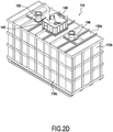
- the dissolution tank 110 of the first container 100 is parallelepipedal and adapted to the dimensions of the first container 100, which is also parallelepiped.
- the first tank 100 has 5 walls of substantially the same dimensions (other than in the longitudinal direction) as 5 walls of the first container against which they are applied, a sixth front transverse side wall 110b of the first tank is however set back from the wall. front transverse side comprising the doors 160 of the first container so as to provide a compartment which can receive a pumping unit 190.
- the pumping unit 190 supplies the parallelepipedic tank 110 with water coming from the tank 30 with the pump 190b and ensures the transfer of the aqueous phase from the first tank 110 to the pipe portion 313 connected to the third tank 310 for preparing the emulsion with the pump 190a.
- Access to the pumping unit 190, for handling operations, is facilitated by the presence in the immediate vicinity of the doors 160 of the front transverse wall of the container 100 but also by the presence of an opening 175 made on the rear longitudinal wall 100b of the first container with regard to the pumping unit 190.
- the mass proportions used for the preparation of the inverse emulsion being from 85 to 95% and preferably from 90 to 94% of aqueous phase for 15 to 5% and preferably 10 to 6% of oily phase
- the production capacity of the modular installation 1 depends directly on the quantity of aqueous phase produced during a cycle of preparation of the emulsion.
- the first tank 110 is closed and is only accessible through the ceiling 110a where openings are formed surrounded by vertical raising walls 135, 136 and 145, the upper ends of which pass through openings in the roof 103 of the first container 100 and protrude above the roof 103 of the first container 100.
- Said vertical riser walls 145 form a cylinder with a square or rectangular section substantially in the center of the ceiling 110a of the first tank, while the small riser walls 135 and 136 arranged on either side of the large ones.
- riser walls 145 are cylindrical in shape with a circular section but may have at their base a plate with a square section to close the possible corresponding square opening of the ceiling 110a of the first tank.
- said first container in addition to the side openings 170, 175 and 370a as well as its door 160 also comprises openings at its roof 103 opposite the openings of said first tank, namely two small openings corresponding to the small extension walls 135 and 136 and a large opening with square or rectangular section allowing the large cylindrical extension wall with square or rectangular section 145 to pass through.
- Two small raising walls 135 and 136 respectively support vertical rods 130c and 131c extending inside the first tank 110 and each supporting two rotary blades 130a, 130b capable of being actuated in rotation about an axis constituted by said rods 131a, 131b.
- Said rotary blades are actuated in rotation by rotary drive motors 130d and 131d arranged above the roof 103 of the first container 100 to constitute stirrers 130 and 131 within the first tank.
- Large side walls 145 located between the two small riser walls 135 and 136, opens out substantially at the center of the roof 110a of the first tank 110 and delimits a manhole through which the nitrate granules are conveyed from an external storage tank 10 to the first tank 110 driven by an external discharge screw 140.
- the riser walls 135, 136 and 155 When transporting the first container, the riser walls 135, 136 and 155 can be separated from the roof of the first tank and the corresponding openings on the roof 103 of the first container from the ceiling 110a of the first tank can be closed using plates also making it possible to reinforce the structure of the container during its transport.
- the elements supported by said small riser walls 135, 136, namely the rods forming the axes of rotation 130c and 131c and the motors 130d and 131d and the discharge screw 140 for the large riser wall 145 can also be dismantled and stored. for their transport.
- a deflector 141 disposed under the central opening delimited by the large extension walls 145 at the top of the roof 110a of the first tank 110 allows the nitrate granules to be deflected in the direction of the two stirrers 130 and 131.
- the granules are easily rotated by the agitators and dissolved in the solution present in the tank.
- the granules could fall in the middle of the tank, beyond sufficient reach of the action of the agitators / mixers.
- the first tank 110 comprises a heat exchanger 120 consisting of a set of three stages 122, 123 and 124 of longitudinal pipes of circular section, parallel and connected to each other in continuity by horizontal pipe elements or transverse connectors 126a to 126f and 128a, 128b for pipes arranged in the same said floor.
- parallel pipes of the same floor is understood here to mean that the pipes of the same floor have their axes situated in parallel planes, said pipes being however slightly inclined at an angle of less than 10 ° with respect to the horizontal, as will be described below, do not have their axes strictly parallel to each other.
- conduits of the exchanger 120 form a continuous network of conduits in which the water vapor coming from the boiler 410 circulates.
- the ends of certain longitudinal conduits at the different stages of the exchanger are connected to those of one stage immediately. upper or lower by elbow vertical pipe elements extending in a vertical plane also called vertical connectors 127a, 127b below.
- the longitudinal pipes are grouped together so as to provide a central free space 120a.
- This free central space 120a allows the passage of the rotating rods and blades of the agitators 130 and 131.
- the third or lower stage 124 on the other hand substantially uniformly covers the entire surface of the floor of the first tank, the longitudinal pipes being spaced therein in the direction. transverse of the same distance from each other.
- the small blades 130a and 131a of the agitators 130 and 131 are located in height between the second and third stages 122 and 123 of the exchanger 120 near the pipes of the third stage 124.
- the large blades 130b and 131b of the agitators 130 and 131 are located above the pipes of the first stage 122 of the exchanger 120.
- the structure of the exchanger 120 and the location of the blades or agitators 130 and 131 are particularly suitable for dissolving nitrates in a parallelepipedal tank.
- the adjacent parallel longitudinal pipes of the same floor are of reverse inclinations and their ends on the same longitudinal side are connected to each other by horizontal transverse connectors.
- the end of at least one longitudinal pipe of each stage is connected to one end on the same side of at least one pipe of a lower or upper stage by angled vertical connectors 127a, 127b.
- the inclination of the various parallel longitudinal conduits favors the flow of the steam and the recovery of the condensates formed by the cooling of the steam in contact with the water or the aqueous phase are promoted at the level of the lower stage.
- the exchanger 120 of the figure 3 comprises 22 longitudinal pipes, the longitudinal axes of which are arranged in planes parallel to each other.
- the 22 longitudinal pipes are arranged symmetrically with respect to a vertical median plane of the exchanger.
- the longitudinal pipes are located near the bottom wall 110c of the tank 110, said parallel longitudinal pipes 124a to 124 are spaced substantially the same distance in the transverse direction.
- a first transverse connector 128a comprises a central discharge orifice 129 constituting a lower outlet orifice of the exchanger 120 allowing the output of the calorific fluid from the exchanger before it does. is transferred and reheated in the boiler 410 and then redirected to the upper supply port 121 described below.
- a first upper transverse connector 126a comprising a central supply orifice 121 supplies the ends of the same side of the 2 longitudinal pipes 122c and 122d delimiting said central space 120a.
- the 2 pipes 122c and 122d are slightly inclined downwardly towards their other longitudinal end up to 2 upper transverse connectors 126b connecting them to the longitudinal ends on the same side of the 2 pipes 122b and 122e respectively.
- These pipes 122b and 122e are in turn inclined in reverse downward slope towards their other longitudinal ends up to transverse connectors 126c connecting them to the longitudinal ends on the same side of the 2 outer pipes 122a and 122f respectively (the most distant therefore from the empty central space 120a).
- the vertical connectors 127a formed of bent pipe elements ensure the connection of said pipes 122a and 122f to the ends located on the same longitudinal side of the pipes 123c and 123d of the second stage of pipes 123.
- the 6 longitudinal conduits parallel to each other 123a to 123f of the second stage 123 are also grouped into 2 groups of 3 conduits arranged symmetrically respectively on each side of the empty central space 120a above the third stage of conduits, namely a first group of pipes 123a, 123b and 123c and a second group of pipes 123d, 123e and 123f.
- the 2 internal longitudinal conduits 123c and 123d of the second stage delimiting the central space 120a are connected to the 2 adjacent conduits 123b and 123e respectively by first intermediate transverse connectors 126th at the longitudinal end opposite that of the first angled vertical connectors 127a.
- first vertical angled connectors 127a ensure the connection between the external conduits 122a and 122f with the internal conduits of the second stage 123c and 123d, it is understood that said vertical bent connectors 127a have a horizontal conduit section in the transverse direction 126f.
- the 2 conduits 123c and 123d are also inclined on a slope in the opposite direction with respect to the conduits 123b and 123e respectively so as to be sloping downward towards their other longitudinal ends to the second intermediate horizontal transverse connectors 126d ensuring their connection with the ends longitudinal on the same longitudinal side of the 2 external pipes of the second stage 123a and 123f respectively.
- the other longitudinal ends located on the same side as the supply 121 and discharge 129 ports, of the 2 external pipes of the second stage 123a and 123f respectively, are connected to the longitudinal ends on the same side of the 2 external pipes of the third stage 124a and 124i by second vertical bent connectors 127b.
- the 2 end conduits 124a and 124j of the third stage 124 are inclined downward from their ends connected to the second vertical connectors 127b to their ends connected to second lower horizontal transverse connectors 128b arranged on the opposite side in the longitudinal direction to the side comprising the supply orifice 121 and discharge orifice 129.
- the 8 parallel longitudinal pipes 124b to 124i of the third floor or lower floor are substantially horizontal or inclined in the opposite direction to that of the 2 external pipes 124a and 124j from said second horizontal transverse connectors 128b towards their other longitudinal ends all connected to the same first lower transverse connector 128a allowing the evacuation of the calorific fluid (vapor) to the central supply port 129.
- water from the tank 30 is introduced into the first tank 110 until it covers the third stage or lower stage 124 of the exchanger, i.e. approximately 1/8 th the height of the tank, ie from 2000 to 5000l, more particularly about 4000 +/- 500 (liters).
- the quantity of water introduced into the tank is measured using a flow meter connected to the central PLC.
- the exchanger 120 is supplied with water vapor and the mixers are activated. The water is thus heated by contact with the third stage 124 of the exchanger associated with the action of the agitator mixers 130 and 131.
- a first portion of ammonium nitrate is introduced into the first tank 110 by the discharge screw 140 with a flow rate of 15 t / h.
- another portion of nitrate is introduced into the first tank. This is done until an amount of about 20T of nitrates has been added to the solution of about 4T of water to obtain about 24T of aqueous phase.
- the pH and humidity are controlled and corrected, if necessary, by adding water to the tank or a weak acid.
- a dissolution additive for example based on thiourea or sodium thiocyanate, is also added, ie approximately 100 kg.
- the first tank When the first tank is filled, above the first stage 122, it comprises mass proportions of approximately 80-82% of nitrate and 18-20% and 0.2 to 0.6% of additives.
- the amount of heat required to dissolve the nitrate supplied by the heat exchanger 120 is approximately 6000 Mega Joules.
- the figures 4A and 4B describe the second container 200 in particular dedicated to the preparation of the oily phase, second step of the process.
- the oily phase is obtained by homogeneous mixture of new or recovered mineral oil (recycled) such as paraffinic oils and fuel oil in proportions varying from 0% to 100%, preferably 50% to 80% of oil to which a surfactant of the nonionic type is added in a proportion by mass of 10 to 30% of the total of the oily phase thus obtained.
- the surfactant aims to facilitate the mixing of the aqueous phase in the oily phase in the form of an inverse emulsion during the third stage of the process within the third container.
- the second container 200 comprises a tank for preparing the oily phase called second tank 210 which is partly cylindrical with a circular section mounted on load cells 240 with an internal volume of V2 of about 3000 l and further comprises furniture and laboratory equipment from analysis 250.
- second tank 210 which is partly cylindrical with a circular section mounted on load cells 240 with an internal volume of V2 of about 3000 l and further comprises furniture and laboratory equipment from analysis 250.
- the load cells 240 make it possible to evaluate the weight of the second tank and of its container in order to control the quantities of oily phase produced or remaining as explained below.
- Laboratory 250 allows to control the quality of the products resulting from the various stages of preparation of the emulsion and the final product.
- the second vessel 210 is a cylindrical vessel with a circular section and comprises within it an internal helical heat exchanger 220 disposed near the internal face of the cylindrical wall of the exchanger.
- the second tank 210 comprises inside the helical exchanger 220 a mixer 230 with rotating blades supported by a vertical rod forming the axis of rotation 230b driven in rotation by a motor 230c placed above the ceiling 210a of the second tank 210
- the helical tubular exchanger 220 is supplied to its upper opening 222 with water vapor coming from the boiler 410 and allows the oily phase to be heated to a temperature above 40-45 ° C, preferably 50-60 ° C.
- the exchanger 220 and the mixer 230a make it possible to obtain a homogeneous oily phase.
- the fuel oil, the oil and the surfactant are introduced successively into the second tank through the upper opening 293a at the level of the ceiling 210a.
- a system of pumps and valves controlled from a control panel 330 makes it possible to select the type of fluid introduced into the second tank 210 via the end 293a of a transfer pipe 293, the other end of which is connected to the pump 280 itself connected to the external tanks 20 of fuel oil, oil and surfactants via pipes connected to pipe connection valves 281, 182 and 283 respectively.
- the quantity of oily phase introduced is measured, during filling, using load cells 240 making it possible to evaluate the weight of the second tank 210.
- the agitator 230 When fuel oil and oil have been introduced into the second tank according to the desired quantity, the agitator 230 is rotated (or actuated) and steam is introduced into the exchanger 220 through the opening 222 of the upper end of the helical coil of the exchanger 220. The surfactant is then introduced into the second tank 210.
- the quantity of steam introduced into the exchanger 220 is regulated so as to obtain the desired temperature of 40-60 ° C, preferably 50-55 ° C in the second tank.
- the oily phase obtained is then kept at constant temperature in the second tank 210 before being conveyed to a portion of pipe 312 connected to the third tank 310 for preparing the emulsion in the third container 300 according to a mass flow rate regulated by a flowmeter 311a in the third container described below.
- the figure 4B shows a rear view in which the various openings of the second container are shown.
- the opening 270a of the second longitudinal wall 200C of the second container gives access to said valves 281, 282, 283 intended to be connected to pipes which are themselves connected to external storage tanks 20 for fuel oil, oil and surfactants.
- the upper opening 270b of the wall 200c gives access to a valve 284 possibly cooperating with a connecting hose 292 supplied with water vapor by the boiler 410.
- the second container 200 also includes a door 261 on its front transverse wall intended to facilitate the passage of an operator to the pumping unit 190 of the container 100 and the doors 260 on its rear transverse wall which can serve as an emergency exit in the event of an incident.
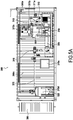
- the figures 5A , 5B and 5C represent the third container 300 for preparing the emulsion, the last step of the process for preparing the emulsion by mixing the aqueous phase and the oily phase.
- the emulsion is produced in the third tank 310 by mixing the aqueous phase in the oily phase, the third tank 310 being equipped with agitators 350.
- the oily phase is produced, during a previous step, at a temperature of 50. at 55 ° C in order to facilitate the temperature difference with the aqueous phase at 80-85 ° C and to facilitate mixing of the two phases.
- the emulsion produced in the third tank 310 being of low viscosity, its consistency makes it unsuitable for its subsequent use for the preparation of the explosive.
- the emulsion is therefore sent, after underdrawing, to a shearing device 315 making it possible to increase the viscosity of the emulsion to a set value.
- the emulsion is then stored temporarily in a buffer tank 320 before being conveyed subsequently to a silo or a storage tank, not shown.
- Temporary storage of the emulsion makes it easy to take samples for quality control at the 250 laboratory. This allows the operator to verify the composition and physical properties of the emulsion without reaching the end of a production run. . He can also have a visual control of the nature of the emulsion produced.
- the preparation of the emulsion in the third tank 310 takes place in two sub-steps.
- the third tank 310 is filled with aqueous phase and with oily phase in proportions by mass of 85-95% of aqueous phase for 5-15% of oily phase using flow meters mass 311a and 311b.
- the third tank 310 is continuously supplied with aqueous phase and with oily phase, while pump 305 continuously withdraws an equivalent quantity of fluid emulsion and sends it into the organ. shear capacity 315.
- the respect of the percentage aqueous phase / oily phase being guaranteed at all times by the use of pumps equipped with mass flow meters.
- the mass flow rate of filling of the aqueous phase will be approximately 13 times greater than that of the oily phase.
- the two sub-steps follow one another so that the third tank 310 is never empty, the emulsion underdraft rate coming from the tank 310 being constant.
- the tank 210 must contain the excess oily phase because the mixing tank or third tank 310 is fed continuously from the first tank 110 and from the second tank 210 until the first tank 110 is exhausted.
- the opening 370a in the front transverse wall 300a of the third container adjacent to the first container 100 allows the passage of pipes the delivery of the aqueous phase from the first tank 110 to the third tank 310 for preparing the emulsion comprising a pipe 313 cooperating with an adjustable flowmeter 311b inside the third container.
- connection element at the end of the pipe portion 313 allowing a rapid connection to be made with a pipe portion extending inside the first container connected to the pumping unit 190 and to the first tank.
- the other openings 370b, 370c and 370d of the third container are located on its rear longitudinal wall 300c not adjacent to the second container.
- the opening 370d located above the third tank 310 for preparing the emulsion makes it possible to communicate with an optional device for extracting vapors from the third tank 310 for preparing the emulsion via pipes. hydraulic.
- the opening 370b located behind the buffer tank 320 and allows the routing of the emulsion to a silo or a storage tank 50 via an evacuation pipe 335 cooperating with a valve 336.
- a pipe 420 is used to supply the first tank of the first container while a steam pipe 430 is used to supply via a connection 284 at the orifice 270b of the free longitudinal wall 200c of the second container, a supply pipe 292 of the end 222 of the helical coil of the exchanger 220.
- the boiler 410 provides the modular steam installation. It could be considered, in other embodiments, that the boiler supplies the installation with hot fluid and in particular hot water.
- ammonium nitrate is used for the preparation of the aqueous phase.
- Sodium or calcium nitrates could also be used.
- the fuel oil and the oil used for the preparation of the oily phase can be replaced by other vegetable and / or mineral oils.
Landscapes
- Chemical & Material Sciences (AREA)
- Engineering & Computer Science (AREA)
- Chemical Kinetics & Catalysis (AREA)
- Mechanical Engineering (AREA)
- Organic Chemistry (AREA)
- Thermal Sciences (AREA)
- Physics & Mathematics (AREA)
- General Engineering & Computer Science (AREA)
- Oil, Petroleum & Natural Gas (AREA)
- Inorganic Chemistry (AREA)
- Colloid Chemistry (AREA)
- Liquid Carbonaceous Fuels (AREA)
- Accessories For Mixers (AREA)
Claims (15)
- Modulare Anlage (1), welche die Durchführung eines Verfahrens zur Herstellung eines Vorläufers einer explosiven Emulsion, der von einer umgekehrten Wasser-in-Öl-Emulsion gebildet ist, ermöglicht, umfassend:a) einen Schritt zur Zubereitung einer wässrigen Phase durch Auflösen von Nitraten in Wasser und Erwärmen, in einem ersten Container (100)b) einen Schritt zur Zubereitung einer öligen Phase durch Mischen von Bestandteilen, die wenigstens ein pflanzliches und/oder mineralisches Fett und ein Tensid umfassen, und Erwärmen, in einem zweiten Container (200), undc) einen Schritt zur Zubereitung der Emulsion durch Mischen der wässrigen Phase in der öligen Phase, in einem dritten Container (300),dadurch gekennzeichnet, dass die modulare Anlage einen ersten Container umfasst, der eine erste Auflösungswannne (110) aufweist, die mit ersten Erwärmungsmitteln (120) und ersten Rührmitteln (130, 131) versehen ist, welche geeignet sind, die in der ersten Wanne enthaltene wässrige Phase zu rühren, wobei die erste Auflösungswanne quaderförmig (110) ist und wenigstens 5 Wände aufweist, die parallel zu und gegen jeweils wenigstens 5 Wände des ersten Containers angeordnet sind, wobei die ersten Erwärmungsmittel der ersten Wanne (110) einen ersten Rohrwärmetauscher (120) umfassen, wobei der erste Rohrwärmetauscher von einem Netz aus zylindrischen Leitungen für den Wärmeträgerfluidtransfer gebildet ist, die durchgehend längs und quer, auf unterschiedlichen Höhenniveaus (122, 123, 124) angeordnet sind, die geeignet sind, die in der ersten quaderförmigen Wanne enthaltene Flüssigkeit dadurch zu erwärmen, dass die Wärme des in dem Leitungsnetz zirkulierenden Wärmeträgerfluids in das gesamte Volumen der ersten Wanne verteilt wird, wobei die zylindrischen Längsleitungen, die im Wesentlichen auf einem gleichen Höhenniveau angeordnet sind, an ihren Enden einer gleichen Seite durch horizontale Querverbinder (126a-126f, 128a-128b) bildende Leitungselemente untereinander verbunden sind, wobei ein Ende wenigstens einer auf einem gegebenen Niveau angeordneten Längsleitung mit dem Ende einer Längsleitung, welche im Bereich der Unterseite oder der Oberseite angeordnet ist, über wenigstens ein gekrümmtes Leitungselement, das sich in einer vertikalen Ebene (127a-127b) erstreckt, verbunden ist, wobei die Leitungen der oberen Niveaus in leicht geneigten Gefällen angeordnet sind, welche gegenüber der Horizontalen in Zirkulationsrichtung des Wärmeträgerfluids, von einer oberen Zufuhröffnung (121) im Bereich eines oberen Querverbinders (126a) zu einer unteren Abführöffnung (129) im Bereich eines ersten unteren Querverbinders (128a) abfallen.
- Modulare Anlage nach Anspruch 1, dadurch gekennzeichnet, dass der erste Wärmetauscher (120) der ersten quaderförmigen Wanne ein Netz aus zylindrischen Längsleitungen umfasst, das eine größere Anzahl von Leitungen im unteren Teil der ersten Wanne umfasst.
- Modulare Anlage nach Anspruch 1 oder 2, dadurch gekennzeichnet, dass der erste Container erste Mittel zum Umpumpen (190, 190a -190b) von wenigstens der wässrigen Phase und des Speisewassers der ersten Wanne von einer ersten äußeren Wanne (30) enthält, die zwischen einer sechsten Querseitenwand (110b) der ersten Wanne und einer vorderen Querseitenwand (160) des ersten Containers gelegen sind.
- Modulare Anlage nach einem der Ansprüche 1 bis 3, dadurch gekennzeichnet, dass die Leitungen der oberen Niveaus in leicht geneigten Gefällen angeordnet sind, welche um einen Winkel kleiner als 10° gegenüber der Horizontalen in Zirkulationsrichtung des Wärmeträgerfluids, von einer oberen Zufuhröffnung (121) im Bereich eines oberen Querverbinders (126a) zu einer unteren Abführöffnung (129) im Bereich eines ersten unteren Querverbinders (128a) abfallen.
- Modulare Anlage nach Anspruch 2 oder 4, dadurch gekennzeichnet, dass der erste Wärmetauscher (120) innerhalb der ersten Wanne umfasst:- eine untere Stufe (124) von Längsleitungen (124a - 124j), die den Boden der ersten quaderförmigen Wanne bedecken, wobei die Leitungen der unteren Stufe in der Querrichtung der ersten Wanne gleichmäßig beabstandet sind und in der Längsrichtung von wenigstens einem zweiten unteren Querverbinder (128b) zu dem ersten unteren Querverbinder (128a) im Wesentlichen horizontal verlaufen, und- wenigstens eine obere Stufe (122, 123) von Längsleitungen in kleinerer Anzahl als die Leitungen der unteren Stufe, wobei die Leitungen der oberen Stufe auf beiden Seiten eines mittleren Raumes (120a) mit einer Abmessung in der Querrichtung der Wanne, die größer als der Raum zwischen zwei benachbarten, auf einer gleichen Seite des mittleren Raumes angeordneten Leitungen ist, zusammengefasst sind, wobei der mittlere Raum (120a) einen Teil der ersten Mittel zum Rühren der wässrigen Phase (130, 131) enthält, und- wobei die benachbarten Längsleitungen einer gleichen Stufe umgekehrte Neigungen aufweisen und ihre Enden einer gleichen Längsseite durch horizontale Querverbinder miteinander verbunden sind.
- Modulare Anlage nach Anspruch 5, dadurch gekennzeichnet, dass ein Teil der ersten Mittel zum Rühren der wässrigen Phase (130a, 131a) auf einer Höhe zwischen der oberen Stufe und der unteren Stufe angeordnet sind, und ein weiterer Teil der ersten Rührmittel (130b, 131b) oberhalb der oberen Stufe angeordnet ist.
- Modulare Anlage nach einem der Ansprüche 1 bis 6, dadurch gekennzeichnet, dass die erste Wanne geschlossen ist, jedoch über verschließbare Öffnungen in ihrer Decke (110a) und des Daches (103) des ersten Containers zugänglich ist.
- Modulare Anlage nach einem der Ansprüche 1 bis 7, dadurch gekennzeichnet, dass das Dach (103) des ersten Containers und die Decke (110a) der ersten Wanne mit einander gegenüberliegenden ersten Öffnungen versehen sind, welche von vorzugsweise lösbaren ersten vertikalen Aufsatzwänden (145) umgeben sind, die sich von der Decke (110a) der ersten Wanne bis oberhalb des Daches (103) des ersten Containers erstrecken, und wobei die ersten Aufsatzwände Elemente tragen oder geeignet sind, Elemente zu tragen, die die Beförderung des Nitrats in die erste Wanne durch die ersten Öffnungen ermöglichen, wobei das Nitrat vorzugsweise mit Hilfe einer Entladeschnecke (140) in die erste Wanne befördert wird, wobei das Nitrat innerhalb der ersten Wanne in Richtung der ersten Rührmittel (130, 131) mit Hilfe wenigstens einer Ablenkeinrichtung (141), welche unter der ersten Öffnung der Decke (110) der ersten Wanne angeordnet ist, verteilt wird, wobei die ersten Öffnungen der Decke der ersten Wanne und des Daches des ersten Containers vorzugsweise verschließbar sind, während des Transports des ersten Containers und der ersten Wanne verschlossen werden können.
- Modulare Anlage nach Anspruch 8, dadurch gekennzeichnet, dass das Dach (103) des ersten Containers und die Decke der ersten Wanne einander gegenüberliegende zweite Öffnungen umfassen, welche von lösbaren zweiten vertikalen Aufsatzwänden (135, 136) umgeben sind, wobei die zweiten Aufsatzwände sich von der Decke (110a) der ersten Wanne bis oberhalb des Daches (103) des ersten Containers erstrecken, wobei die zweiten Aufsatzwände erste Rührmittel (130, 131) tragen, die wenigstens eine sich innerhalb der ersten Wanne erstreckende vertikale Stange (130c, 131c) umfassen, an der umlaufende Rührschaufeln (130a-130b, 131a-131b) angebracht sind, welche geeignet sind, mit Hilfe eines Motors (130d, 131d) um eine vertikale Achse drehangetrieben zu werden, wobei der Motor an dem Dach des ersten Containers nicht dauerhaft angebracht ist, wobei die zweiten Öffnungen verschließbar sind, wodurch sie während des Transports verschlossen werden können.
- Modulare Anlage nach einem der Ansprüche 1 bis 9, dadurch gekennzeichnet, dass die modulare Anlage wenigstens die folgenden zusätzlichen Container umfasst:- einen zweiten Container (200), der eine zweite Wanne (210) enthält, welche zweite Erwärmungsmittel (220) und zweite Rührmittel (230), die für die Zubereitung der öligen Phase bestimmt sind, enthält, und- einen dritten Container (300), der eine dritte Wanne (310) enthält, die dritte Rührmittel (330), welche für die Zubereitung der Emulsion bestimmt sind, enthält.
- Modulare Anlage nach einem der Ansprüche 1 bis 10, dadurch gekennzeichnet dass die erste Wanne (110) einen Wärmetauscher (120) umfasst, der aus einer Anordnung von drei Stufen (122, 123 und 124) von Längsleitungen mit kreisförmigem Querschnitt besteht, welche durch horizontale Leitungselemente oder Querverbinder (126a bis 126f und 128a, 128b) für die in einer gleichen Stufe angeordneten Leitungen durchgehend miteinander verbunden sind, wobei die Enden von einigen Längsleitungen in unterschiedlichen Stufen des Tauschers mit denjenigen einer unmittelbar oberen oder unteren Stufe durch vertikale gekrümmte Leitungselemente, die sich in einer vertikalen Ebene erstrecken, die auch als vertikale Verbinder (127a, 127b) bezeichnet werden, verbunden sind, wobei die Längsleitungen im Bereich der ersten Stufe (122) und zweiten Stufe (123) derart zusammengefasst sind, dass sie einen freien mittleren Raum (120a) ausbilden, der den Durchgang von Stangen und rotierenden Rührvorrichtungsschaufeln (130 und 131) ermöglicht, wobei die dritte Stufe oder untere Stufe (124), die gesamte Fläche des Bodens der ersten Wanne im Wesentlichen gleichmäßig bedeckt, wobei die Längsleitungen dort in der Querrichtung um einen gleichen Abstand voneinander beabstandet sind, wobei die kleinsten Schaufeln (130a und 131a) der Rührvorrichtungen (130 und 131) in der Höhe zwischen der zweiten und der dritten Stufe (122 und 123) des Tauschers (120) in der Nähe der Leitungen der dritten Stufe (124) gelegen sind, wobei die größten Schaufeln (130b und 131b) der Rührvorrichtungen (130 und 131) oberhalb der Leitungen der ersten Stufe (122) des Tauschers (120) gelegen sind.
- Modulare Anlage nach Anspruch 11, dadurch gekennzeichnet, dass die modulare Anlage die zusätzlichen Container umfasst, welche wie folgt angeordnet sind:- wobei wenigstens einer der zweiten und/oder dritten Container zweite Mittel zum Umpumpen der öligen Phase (290) von der zweiten Wanne zu der dritten Wanne und zum Zirkulieren der Bestandteile der öligen Phase (280) von äußeren Wannen zur Lagerung der Bestandteile (20) zu der zweiten Wanne sowie dritte Umpumpmittel zum Abführen der Emulsion (305) von der dritten Wanne zu einer Wanne zur Lagerung der Emulsion umfasst, und- wenigstens einen vierten und/oder fünften Container (400, 500), umfassend Mittel zur Bereitstellung von Wärmeträgerfluid (410), die ermöglichen, die Erwärmungsmittel mit Wärmeträgerfluid zu beaufschlagen, und Mittel zur Bereitstellung von elektrischer Energie (510), die ermöglichen, wenigstens die Mittel zum Umpumpen von Fluid und die Rührmittel mit Strom zu versorgen, vorzugsweise einen vierten Container (400), der Mittel zur Bereitstellung von Wärmeträgerfluid (410) enthält, und einen fünften Container (500), der Mittel zur Bereitstellung von elektrischer Energie (510) enthält,
wobei der erste, der zweite und/oder der dritte Container (100, 200, 300) wenigstens über einen Teil von einer ihrer Seitenwände (100a, 300a, 300b, 200b) nebeneinander angeordnet sind, so dass wenigstens ein Teil einer Seitenwand des ersten Containers wenigstens neben einem Teil einer Seitenwand des dritten Containers gelegen ist und wenigstens ein Teil einer Seitenwand des zweiten Containers wenigstens neben einem Teil einer anderen Seitenwand des dritten Containers gelegen ist, so dass der dritte Container zwischen dem ersten Container und dem zweiten Container eingefügt ist, und- wobei der erste, der zweite und/oder der dritte Container im Bereich ihrer Wände Öffnungen (170, 370a, 275, 375, 270b, 370b) umfassen, über die Fluidtransferleitungen zwischen den Containern und/oder Stromkabel verlaufen und/oder verbunden sind,- wobei die Öffnungen verschließbar sind, insbesondere während des Transports der Container verschlossen werden können. - Modulare Anlage nach einem der Ansprüche 1 bis 12, dadurch gekennzeichnet, dass der zweite Container (200), der für die Zubereitung der öligen Phase (200) bestimmt ist, eine durch Schnellwaagen (240) getragene einzige zweite Wanne (210) umfasst, mit - innerhalb der zweiten Wanne - zweiten Erwärmungsmitteln, die einen schraubenförmigen zweiten Wärmetauscher (220) umfassen.
- Modulare Anlage nach einem der Ansprüche 1 bis 13, dadurch gekennzeichnet, dass der dritte Container (300), der für die Zubereitung der Emulsion (300) bestimmt ist, eine dritte Mischwanne (310), eine Schervorrichtung (315) zum kontrollierten Erhöhen der Viskosität der Emulsion umfasst, die aus der dritten Wanne (310) in Richtung einer vierten Pufferwanne (320) abgeführt wird, welche dazu bestimmt ist, die in der dritten Wanne zubereitete Emulsion für eine Analyse vor dem Abführen zu einer äußeren Wanne zur Lagerung der Emulsion (50) außerhalb des dritten Containers vorübergehend aufzunehmen, und der zweite Container und/oder der dritte Container (200, 300) Analyselabormobiliar und -gerät (250), ein Pult zur Steuerung (330) der verschiedenen Umpumpmittel, Erwärmungsmittel und Rührmittel umfassen.
- Verfahren zur Zubereitung eines von einer Emulsion gebildeten Sprengstoffvorläufers durch Verwendung einer modularen Anlage nach einem der Ansprüche 10 bis 13, umfassend:a) einen Schritt zur Zubereitung einer wässrigen Phase durch Auflösen von Nitraten in Wasser und Erwärmen innerhalb der ersten Wanne,b) einen Schritt zur Zubereitung einer öligen Phase und Erwärmen innerhalb der zweiten Wanne, undc) einen Schritt zur Zubereitung der Emulsion durch Mischen der wässrigen Phase in der öligen Phase innerhalb der dritten Wanne, ohne Erwärmen.
Priority Applications (1)
| Application Number | Priority Date | Filing Date | Title |
|---|---|---|---|
| PL14191011T PL2845844T3 (pl) | 2013-01-16 | 2014-01-09 | Instalacja modułowa do wytwarzania prekursora emulsji wybuchowej |
Applications Claiming Priority (3)
| Application Number | Priority Date | Filing Date | Title |
|---|---|---|---|
| FR1350379A FR3000957A1 (fr) | 2013-01-16 | 2013-01-16 | Installation modulaire de fabrication d'un precurseur d'emulsion explosive |
| PCT/FR2014/050032 WO2014111644A1 (fr) | 2013-01-16 | 2014-01-09 | Installation modulaire de fabrication d'un precurseur d'emulsion explosive |
| EP14703120.7A EP2828226B1 (de) | 2013-01-16 | 2014-01-09 | Modulare anlage zur herstellung eines explosiven emulsionsvorläufers |
Related Parent Applications (2)
| Application Number | Title | Priority Date | Filing Date |
|---|---|---|---|
| EP14703120.7A Division EP2828226B1 (de) | 2013-01-16 | 2014-01-09 | Modulare anlage zur herstellung eines explosiven emulsionsvorläufers |
| EP14703120.7A Division-Into EP2828226B1 (de) | 2013-01-16 | 2014-01-09 | Modulare anlage zur herstellung eines explosiven emulsionsvorläufers |
Publications (3)
| Publication Number | Publication Date |
|---|---|
| EP2845844A2 EP2845844A2 (de) | 2015-03-11 |
| EP2845844A3 EP2845844A3 (de) | 2015-11-11 |
| EP2845844B1 true EP2845844B1 (de) | 2021-02-17 |
Family
ID=48521137
Family Applications (2)
| Application Number | Title | Priority Date | Filing Date |
|---|---|---|---|
| EP14191011.7A Active EP2845844B1 (de) | 2013-01-16 | 2014-01-09 | Modulare Anlage zur Herstellung eines Vorläufers einer explosiven Emulsion |
| EP14703120.7A Active EP2828226B1 (de) | 2013-01-16 | 2014-01-09 | Modulare anlage zur herstellung eines explosiven emulsionsvorläufers |
Family Applications After (1)
| Application Number | Title | Priority Date | Filing Date |
|---|---|---|---|
| EP14703120.7A Active EP2828226B1 (de) | 2013-01-16 | 2014-01-09 | Modulare anlage zur herstellung eines explosiven emulsionsvorläufers |
Country Status (8)
| Country | Link |
|---|---|
| US (1) | US9670107B2 (de) |
| EP (2) | EP2845844B1 (de) |
| DK (1) | DK2845844T3 (de) |
| ES (2) | ES2673577T3 (de) |
| FR (1) | FR3000957A1 (de) |
| PL (1) | PL2845844T3 (de) |
| TR (1) | TR201808346T4 (de) |
| WO (1) | WO2014111644A1 (de) |
Families Citing this family (4)
| Publication number | Priority date | Publication date | Assignee | Title |
|---|---|---|---|---|
| CN107596946A (zh) * | 2017-11-07 | 2018-01-19 | 河南道骐汽车科技有限公司 | 一种润滑油生产用调和罐 |
| CN113831203B (zh) * | 2021-11-10 | 2022-05-10 | 黑龙江盛安民用爆破器材有限责任公司 | 一种含有钙盐的乳化炸药制备方法以及制备装置 |
| CN114699985B (zh) * | 2022-03-31 | 2023-06-13 | 神华准格尔能源有限责任公司 | 水溶液配置方法、设备及计算机可读存储介质 |
| FR3134730B1 (fr) * | 2022-04-26 | 2024-10-25 | Nitrates & Innovation | Installation modulaire compacte pour la préparation d’un précurseur d’émulsion explosive |
Family Cites Families (20)
| Publication number | Priority date | Publication date | Assignee | Title |
|---|---|---|---|---|
| DE398710C (de) * | 1924-07-10 | Maschb Akt Ges Balcke | Aus mehreren Einzelzellen bestehende Vorrichtung zum Loesen von Salzen, insbesondereKalisalzen | |
| DE454677C (de) * | 1928-01-14 | Dorr Co | Zum Loesen von feinkoernigen Stoffen dienender Behaelter | |
| US3442727A (en) * | 1967-08-03 | 1969-05-06 | Atlas Chem Ind | Emulsified nitric acid blasting composition and method of preparing same |
| DE2341974A1 (de) * | 1973-08-20 | 1975-03-13 | Leifeld & Co | Verfahren zum umformen von rohren |
| ZW16283A1 (en) * | 1982-07-28 | 1984-03-07 | Aeci Ltd | Explosives mixing device |
| US4526633A (en) * | 1982-11-08 | 1985-07-02 | Ireco Incorporated | Formulating and delivery system for emulsion blasting |
| ES2048205T3 (es) * | 1987-12-17 | 1994-03-16 | Ici Plc | Metodo y aparato para emulsificacion. |
| US5346564A (en) * | 1993-06-16 | 1994-09-13 | Nelson Brothers, Inc. | Method of safely preparing an explosive emulsion composition |
| FR2730647B1 (fr) * | 1995-02-20 | 1997-04-04 | Elf Antar France | Installation de melange et de conditionnement de produits liquides |
| AUPN737395A0 (en) * | 1995-12-29 | 1996-01-25 | Ici Australia Operations Proprietary Limited | Process and apparatus for the manufacture of emulsion explosive compositions |
| US6113715A (en) * | 1998-07-09 | 2000-09-05 | Dyno Nobel Inc. | Method for forming an emulsion explosive composition |
| CA2381121C (en) * | 1999-07-09 | 2007-07-31 | Union Espanola De Explosivos, S.A. | Procedure and installation for on-site manufacturing of explosives made from a water based oxidizing product |
| DE10104311C1 (de) * | 2001-01-22 | 2002-08-14 | Berstorff Gmbh | Compoundieranlage |
| US6808573B2 (en) * | 2002-09-23 | 2004-10-26 | Dyno Nobel Inc. | Emulsion phase having improved stability |
| CA2519591C (en) * | 2003-03-21 | 2011-07-12 | Ifac Gmbh & Co. Kg | Device and method for continuously producing emulsions or dispersions |
| DE102005021610A1 (de) * | 2005-05-10 | 2006-11-23 | BSH Bosch und Siemens Hausgeräte GmbH | Wärmetauscher |
| US8282752B2 (en) * | 2008-01-23 | 2012-10-09 | Orica Explosives Technology Pty Ltd | Mobile delivery platform for flowable explosive |
| DE202008009297U1 (de) * | 2008-07-10 | 2008-09-04 | Mat Mischanlagentechnik Gmbh | Kompaktanlage zur Suspensionsaufbereitung |
| DE102009052748B4 (de) * | 2009-11-11 | 2013-07-04 | Coperion Gmbh | Container-Compoundieranlage |
| AU2013323054A1 (en) * | 2012-09-26 | 2015-04-16 | Basf Se | Device for heating or cooling a meltable material |
-
2013
- 2013-01-16 FR FR1350379A patent/FR3000957A1/fr not_active Withdrawn
-
2014
- 2014-01-09 EP EP14191011.7A patent/EP2845844B1/de active Active
- 2014-01-09 ES ES14703120.7T patent/ES2673577T3/es active Active
- 2014-01-09 ES ES14191011T patent/ES2865129T3/es active Active
- 2014-01-09 PL PL14191011T patent/PL2845844T3/pl unknown
- 2014-01-09 DK DK14191011.7T patent/DK2845844T3/da active
- 2014-01-09 WO PCT/FR2014/050032 patent/WO2014111644A1/fr not_active Ceased
- 2014-01-09 EP EP14703120.7A patent/EP2828226B1/de active Active
- 2014-01-09 US US14/401,347 patent/US9670107B2/en active Active
- 2014-01-09 TR TR2018/08346T patent/TR201808346T4/en unknown
Non-Patent Citations (1)
| Title |
|---|
| None * |
Also Published As
| Publication number | Publication date |
|---|---|
| WO2014111644A1 (fr) | 2014-07-24 |
| US20150144236A1 (en) | 2015-05-28 |
| US9670107B2 (en) | 2017-06-06 |
| EP2845844A3 (de) | 2015-11-11 |
| EP2828226A1 (de) | 2015-01-28 |
| FR3000957A1 (fr) | 2014-07-18 |
| EP2828226B1 (de) | 2018-03-14 |
| ES2865129T3 (es) | 2021-10-15 |
| PL2845844T3 (pl) | 2021-08-02 |
| ES2673577T3 (es) | 2018-06-22 |
| DK2845844T3 (da) | 2021-05-17 |
| EP2845844A2 (de) | 2015-03-11 |
| TR201808346T4 (en) | 2018-07-23 |
Similar Documents
| Publication | Publication Date | Title |
|---|---|---|
| EP2828226B1 (de) | Modulare anlage zur herstellung eines explosiven emulsionsvorläufers | |
| EP2776705B1 (de) | Pumpspeicherkraftwerk | |
| EP3119736A1 (de) | Verfahren zur herstellung eines sprengstoffs durch mischung mit einem vergasungsreagenz | |
| EP1321262B1 (de) | Anlage zum Herstellen und Transportieren von Mörtel | |
| FR3050205A1 (fr) | Melangeur statique avec un dispositif de cisaillement et procede de production d'explosif | |
| EP4490134A1 (de) | Kompakte modulare anlage zur herstellung eines explosiven emulsionsvorläufers | |
| US5868327A (en) | Mixing and dispensing apparatus and method | |
| EP0956165A1 (de) | Verfahren und vielzweckvorrichtung zur erhaltung metastabiler flüssigkeiten | |
| EP3119735B1 (de) | Anlage zur erzeugung eines sprengstoffs durch mischung mit einem vergasungsreagenz | |
| EP3318341B1 (de) | Vorrichtung und verfahren für die methanisierung durch trockenverfahren von organischem material. | |
| CN221715298U (zh) | 一种林业土壤用修复装置 | |
| FR3131857A1 (fr) | Installation de stockage et d’utilisation de polymeres hydrosolubles | |
| FR3012346A1 (fr) | Cuve pour une installation de methanisation pour la production de biogaz | |
| RU2223856C1 (ru) | Установка смесительная механическая | |
| EP0756516A1 (de) | Anlage zum mischen und konditionieren von flüssigkeiten | |
| CN216645095U (zh) | 一种烟花生产用填药装置 | |
| FR2570254A1 (fr) | Procede pour la preparation de fourrage additionne d'eau et installation pour la realisation du procede | |
| FR2679796A1 (fr) | Machine et methode de projection d'un melange comportant des produits de granulometries variables. | |
| FR2917324A1 (fr) | Installation de preparation d'un materiau humide de type beton ou mortier | |
| CN108499442B (zh) | 一种利用水力蓄能进行工业搅拌溶液的装置及其工艺 | |
| FR3069239A1 (fr) | Conteneur autonome de methanisation pour voie liquide | |
| WO2024186195A1 (fr) | Système autonome de production de l'énergie hydroélectrique en circuit fermé | |
| FR3045681A1 (fr) | Procede et dispositif de stockage de granulats | |
| EP0735002A1 (de) | Verfahren und Vorrichtung zur Lösung einer Magnesiumverbindung in Wasser | |
| FR3116695A1 (fr) | Procede et installation de preparation et de distribution d'une composition alimentaire liquide pour animaux d'elevage |
Legal Events
| Date | Code | Title | Description |
|---|---|---|---|
| 17P | Request for examination filed |
Effective date: 20141030 |
|
| AC | Divisional application: reference to earlier application |
Ref document number: 2828226 Country of ref document: EP Kind code of ref document: P |
|
| AK | Designated contracting states |
Kind code of ref document: A2 Designated state(s): AL AT BE BG CH CY CZ DE DK EE ES FI FR GB GR HR HU IE IS IT LI LT LU LV MC MK MT NL NO PL PT RO RS SE SI SK SM TR |
|
| AX | Request for extension of the european patent |
Extension state: BA ME |
|
| PUAI | Public reference made under article 153(3) epc to a published international application that has entered the european phase |
Free format text: ORIGINAL CODE: 0009012 |
|
| PUAL | Search report despatched |
Free format text: ORIGINAL CODE: 0009013 |
|
| AK | Designated contracting states |
Kind code of ref document: A3 Designated state(s): AL AT BE BG CH CY CZ DE DK EE ES FI FR GB GR HR HU IE IS IT LI LT LU LV MC MK MT NL NO PL PT RO RS SE SI SK SM TR |
|
| AX | Request for extension of the european patent |
Extension state: BA ME |
|
| RIC1 | Information provided on ipc code assigned before grant |
Ipc: C06B 21/00 20060101ALI20151002BHEP Ipc: F28B 1/02 20060101ALI20151002BHEP Ipc: B01F 7/16 20060101ALI20151002BHEP Ipc: C06B 47/14 20060101AFI20151002BHEP Ipc: F28F 13/12 20060101ALI20151002BHEP Ipc: B01F 7/18 20060101ALI20151002BHEP Ipc: F28D 1/02 20060101ALI20151002BHEP Ipc: F28F 9/26 20060101ALI20151002BHEP Ipc: B01F 15/06 20060101ALI20151002BHEP Ipc: B01F 1/00 20060101ALI20151002BHEP Ipc: B01F 7/00 20060101ALI20151002BHEP |
|
| R17P | Request for examination filed (corrected) |
Effective date: 20160316 |
|
| RBV | Designated contracting states (corrected) |
Designated state(s): AL AT BE BG CH CY CZ DE DK EE ES FI FR GB GR HR HU IE IS IT LI LT LU LV MC MK MT NL NO PL PT RO RS SE SI SK SM TR |
|
| STAA | Information on the status of an ep patent application or granted ep patent |
Free format text: STATUS: EXAMINATION IS IN PROGRESS |
|
| 17Q | First examination report despatched |
Effective date: 20180102 |
|
| GRAP | Despatch of communication of intention to grant a patent |
Free format text: ORIGINAL CODE: EPIDOSNIGR1 |
|
| STAA | Information on the status of an ep patent application or granted ep patent |
Free format text: STATUS: GRANT OF PATENT IS INTENDED |
|
| INTG | Intention to grant announced |
Effective date: 20201112 |
|
| GRAS | Grant fee paid |
Free format text: ORIGINAL CODE: EPIDOSNIGR3 |
|
| GRAA | (expected) grant |
Free format text: ORIGINAL CODE: 0009210 |
|
| STAA | Information on the status of an ep patent application or granted ep patent |
Free format text: STATUS: THE PATENT HAS BEEN GRANTED |
|
| AC | Divisional application: reference to earlier application |
Ref document number: 2828226 Country of ref document: EP Kind code of ref document: P |
|
| AK | Designated contracting states |
Kind code of ref document: B1 Designated state(s): AL AT BE BG CH CY CZ DE DK EE ES FI FR GB GR HR HU IE IS IT LI LT LU LV MC MK MT NL NO PL PT RO RS SE SI SK SM TR |
|
| RAP1 | Party data changed (applicant data changed or rights of an application transferred) |
Owner name: NITRATES & INNOVATION |
|
| REG | Reference to a national code |
Ref country code: GB Ref legal event code: FG4D Free format text: NOT ENGLISH |
|
| REG | Reference to a national code |
Ref country code: CH Ref legal event code: EP |
|
| REG | Reference to a national code |
Ref country code: DE Ref legal event code: R096 Ref document number: 602014074784 Country of ref document: DE |
|
| REG | Reference to a national code |
Ref country code: AT Ref legal event code: REF Ref document number: 1361268 Country of ref document: AT Kind code of ref document: T Effective date: 20210315 |
|
| REG | Reference to a national code |
Ref country code: IE Ref legal event code: FG4D Free format text: LANGUAGE OF EP DOCUMENT: FRENCH |
|
| REG | Reference to a national code |
Ref country code: SE Ref legal event code: TRGR |
|
| REG | Reference to a national code |
Ref country code: FI Ref legal event code: FGE |
|
| RAP4 | Party data changed (patent owner data changed or rights of a patent transferred) |
Owner name: NITRATES & INNOVATION |
|
| REG | Reference to a national code |
Ref country code: DK Ref legal event code: T3 Effective date: 20210512 |
|
| REG | Reference to a national code |
Ref country code: LT Ref legal event code: MG9D |
|
| REG | Reference to a national code |
Ref country code: NL Ref legal event code: MP Effective date: 20210217 |
|
| PG25 | Lapsed in a contracting state [announced via postgrant information from national office to epo] |
Ref country code: LT Free format text: LAPSE BECAUSE OF FAILURE TO SUBMIT A TRANSLATION OF THE DESCRIPTION OR TO PAY THE FEE WITHIN THE PRESCRIBED TIME-LIMIT Effective date: 20210217 Ref country code: PT Free format text: LAPSE BECAUSE OF FAILURE TO SUBMIT A TRANSLATION OF THE DESCRIPTION OR TO PAY THE FEE WITHIN THE PRESCRIBED TIME-LIMIT Effective date: 20210617 Ref country code: GR Free format text: LAPSE BECAUSE OF FAILURE TO SUBMIT A TRANSLATION OF THE DESCRIPTION OR TO PAY THE FEE WITHIN THE PRESCRIBED TIME-LIMIT Effective date: 20210518 Ref country code: HR Free format text: LAPSE BECAUSE OF FAILURE TO SUBMIT A TRANSLATION OF THE DESCRIPTION OR TO PAY THE FEE WITHIN THE PRESCRIBED TIME-LIMIT Effective date: 20210217 Ref country code: BG Free format text: LAPSE BECAUSE OF FAILURE TO SUBMIT A TRANSLATION OF THE DESCRIPTION OR TO PAY THE FEE WITHIN THE PRESCRIBED TIME-LIMIT Effective date: 20210517 Ref country code: NO Free format text: LAPSE BECAUSE OF FAILURE TO SUBMIT A TRANSLATION OF THE DESCRIPTION OR TO PAY THE FEE WITHIN THE PRESCRIBED TIME-LIMIT Effective date: 20210517 |
|
| REG | Reference to a national code |
Ref country code: AT Ref legal event code: MK05 Ref document number: 1361268 Country of ref document: AT Kind code of ref document: T Effective date: 20210217 |
|
| PG25 | Lapsed in a contracting state [announced via postgrant information from national office to epo] |
Ref country code: RS Free format text: LAPSE BECAUSE OF FAILURE TO SUBMIT A TRANSLATION OF THE DESCRIPTION OR TO PAY THE FEE WITHIN THE PRESCRIBED TIME-LIMIT Effective date: 20210217 Ref country code: LV Free format text: LAPSE BECAUSE OF FAILURE TO SUBMIT A TRANSLATION OF THE DESCRIPTION OR TO PAY THE FEE WITHIN THE PRESCRIBED TIME-LIMIT Effective date: 20210217 Ref country code: NL Free format text: LAPSE BECAUSE OF FAILURE TO SUBMIT A TRANSLATION OF THE DESCRIPTION OR TO PAY THE FEE WITHIN THE PRESCRIBED TIME-LIMIT Effective date: 20210217 |
|
| PG25 | Lapsed in a contracting state [announced via postgrant information from national office to epo] |
Ref country code: IS Free format text: LAPSE BECAUSE OF FAILURE TO SUBMIT A TRANSLATION OF THE DESCRIPTION OR TO PAY THE FEE WITHIN THE PRESCRIBED TIME-LIMIT Effective date: 20210617 |
|
| REG | Reference to a national code |
Ref country code: ES Ref legal event code: FG2A Ref document number: 2865129 Country of ref document: ES Kind code of ref document: T3 Effective date: 20211015 |
|
| PG25 | Lapsed in a contracting state [announced via postgrant information from national office to epo] |
Ref country code: SM Free format text: LAPSE BECAUSE OF FAILURE TO SUBMIT A TRANSLATION OF THE DESCRIPTION OR TO PAY THE FEE WITHIN THE PRESCRIBED TIME-LIMIT Effective date: 20210217 Ref country code: EE Free format text: LAPSE BECAUSE OF FAILURE TO SUBMIT A TRANSLATION OF THE DESCRIPTION OR TO PAY THE FEE WITHIN THE PRESCRIBED TIME-LIMIT Effective date: 20210217 Ref country code: CZ Free format text: LAPSE BECAUSE OF FAILURE TO SUBMIT A TRANSLATION OF THE DESCRIPTION OR TO PAY THE FEE WITHIN THE PRESCRIBED TIME-LIMIT Effective date: 20210217 Ref country code: AT Free format text: LAPSE BECAUSE OF FAILURE TO SUBMIT A TRANSLATION OF THE DESCRIPTION OR TO PAY THE FEE WITHIN THE PRESCRIBED TIME-LIMIT Effective date: 20210217 |
|
| REG | Reference to a national code |
Ref country code: DE Ref legal event code: R097 Ref document number: 602014074784 Country of ref document: DE |
|
| PG25 | Lapsed in a contracting state [announced via postgrant information from national office to epo] |
Ref country code: RO Free format text: LAPSE BECAUSE OF FAILURE TO SUBMIT A TRANSLATION OF THE DESCRIPTION OR TO PAY THE FEE WITHIN THE PRESCRIBED TIME-LIMIT Effective date: 20210217 Ref country code: SK Free format text: LAPSE BECAUSE OF FAILURE TO SUBMIT A TRANSLATION OF THE DESCRIPTION OR TO PAY THE FEE WITHIN THE PRESCRIBED TIME-LIMIT Effective date: 20210217 |
|
| PLBE | No opposition filed within time limit |
Free format text: ORIGINAL CODE: 0009261 |
|
| STAA | Information on the status of an ep patent application or granted ep patent |
Free format text: STATUS: NO OPPOSITION FILED WITHIN TIME LIMIT |
|
| 26N | No opposition filed |
Effective date: 20211118 |
|
| PG25 | Lapsed in a contracting state [announced via postgrant information from national office to epo] |
Ref country code: AL Free format text: LAPSE BECAUSE OF FAILURE TO SUBMIT A TRANSLATION OF THE DESCRIPTION OR TO PAY THE FEE WITHIN THE PRESCRIBED TIME-LIMIT Effective date: 20210217 |
|
| PG25 | Lapsed in a contracting state [announced via postgrant information from national office to epo] |
Ref country code: SI Free format text: LAPSE BECAUSE OF FAILURE TO SUBMIT A TRANSLATION OF THE DESCRIPTION OR TO PAY THE FEE WITHIN THE PRESCRIBED TIME-LIMIT Effective date: 20210217 |
|
| PG25 | Lapsed in a contracting state [announced via postgrant information from national office to epo] |
Ref country code: IS Free format text: LAPSE BECAUSE OF FAILURE TO SUBMIT A TRANSLATION OF THE DESCRIPTION OR TO PAY THE FEE WITHIN THE PRESCRIBED TIME-LIMIT Effective date: 20210617 |
|
| PG25 | Lapsed in a contracting state [announced via postgrant information from national office to epo] |
Ref country code: MC Free format text: LAPSE BECAUSE OF FAILURE TO SUBMIT A TRANSLATION OF THE DESCRIPTION OR TO PAY THE FEE WITHIN THE PRESCRIBED TIME-LIMIT Effective date: 20210217 |
|
| PG25 | Lapsed in a contracting state [announced via postgrant information from national office to epo] |
Ref country code: LU Free format text: LAPSE BECAUSE OF NON-PAYMENT OF DUE FEES Effective date: 20220109 |
|
| REG | Reference to a national code |
Ref country code: DE Ref legal event code: R082 Ref document number: 602014074784 Country of ref document: DE Representative=s name: CBDL PATENTANWAELTE EGBR, DE Ref country code: DE Ref legal event code: R082 Ref document number: 602014074784 Country of ref document: DE Representative=s name: CBDL PATENTANWAELTE GBR, DE Ref country code: DE Ref legal event code: R082 Ref document number: 602014074784 Country of ref document: DE Representative=s name: PLASSERAUD IP GMBH, DE |
|
| REG | Reference to a national code |
Ref country code: ES Ref legal event code: PC2A Owner name: INNOVATION & INDUSTRIE Effective date: 20230622 |
|
| REG | Reference to a national code |
Ref country code: DE Ref legal event code: R081 Ref document number: 602014074784 Country of ref document: DE Owner name: INNOVATION & INDUSTRIE, FR Free format text: FORMER OWNER: NITRATES&INNOVATION, PARIS, FR |
|
| REG | Reference to a national code |
Ref country code: BE Ref legal event code: HC Free format text: DETAILS ASSIGNMENT: CHANGE OF OWNER(S), CHANGE OF OWNER(S) NAME Effective date: 20230728 |
|
| REG | Reference to a national code |
Ref country code: BE Ref legal event code: HC Owner name: INNOVATION & INDUSTRIE; FR Free format text: DETAILS ASSIGNMENT: CHANGE OF OWNER(S), CHANGE OF OWNER(S) NAME; FORMER OWNER NAME: NITRATES & INNOVATION Effective date: 20231221 |
|
| PG25 | Lapsed in a contracting state [announced via postgrant information from national office to epo] |
Ref country code: HU Free format text: LAPSE BECAUSE OF FAILURE TO SUBMIT A TRANSLATION OF THE DESCRIPTION OR TO PAY THE FEE WITHIN THE PRESCRIBED TIME-LIMIT; INVALID AB INITIO Effective date: 20140109 |
|
| PG25 | Lapsed in a contracting state [announced via postgrant information from national office to epo] |
Ref country code: MK Free format text: LAPSE BECAUSE OF FAILURE TO SUBMIT A TRANSLATION OF THE DESCRIPTION OR TO PAY THE FEE WITHIN THE PRESCRIBED TIME-LIMIT Effective date: 20210217 Ref country code: CY Free format text: LAPSE BECAUSE OF FAILURE TO SUBMIT A TRANSLATION OF THE DESCRIPTION OR TO PAY THE FEE WITHIN THE PRESCRIBED TIME-LIMIT Effective date: 20210217 |
|
| PG25 | Lapsed in a contracting state [announced via postgrant information from national office to epo] |
Ref country code: MT Free format text: LAPSE BECAUSE OF FAILURE TO SUBMIT A TRANSLATION OF THE DESCRIPTION OR TO PAY THE FEE WITHIN THE PRESCRIBED TIME-LIMIT Effective date: 20210217 |
|
| PGFP | Annual fee paid to national office [announced via postgrant information from national office to epo] |
Ref country code: FI Payment date: 20251224 Year of fee payment: 13 Ref country code: DK Payment date: 20251230 Year of fee payment: 13 |
|
| PGFP | Annual fee paid to national office [announced via postgrant information from national office to epo] |
Ref country code: FR Payment date: 20251126 Year of fee payment: 13 |
|
| PGFP | Annual fee paid to national office [announced via postgrant information from national office to epo] |
Ref country code: IE Payment date: 20251223 Year of fee payment: 13 |
|
| PGFP | Annual fee paid to national office [announced via postgrant information from national office to epo] |
Ref country code: PL Payment date: 20251205 Year of fee payment: 13 |
|
| REG | Reference to a national code |
Ref country code: CH Ref legal event code: U11 Free format text: ST27 STATUS EVENT CODE: U-0-0-U10-U11 (AS PROVIDED BY THE NATIONAL OFFICE) Effective date: 20260201 |
|
| PGFP | Annual fee paid to national office [announced via postgrant information from national office to epo] |
Ref country code: SE Payment date: 20260127 Year of fee payment: 13 |
|
| PGFP | Annual fee paid to national office [announced via postgrant information from national office to epo] |
Ref country code: GB Payment date: 20260127 Year of fee payment: 13 |
|
| PGFP | Annual fee paid to national office [announced via postgrant information from national office to epo] |
Ref country code: ES Payment date: 20260209 Year of fee payment: 13 |
|
| PGFP | Annual fee paid to national office [announced via postgrant information from national office to epo] |
Ref country code: DE Payment date: 20260114 Year of fee payment: 13 |
|
| REG | Reference to a national code |
Ref country code: DE Ref legal event code: R082 Ref document number: 602014074784 Country of ref document: DE Ref country code: DE Ref legal event code: R082 Ref document number: 602014074784 Country of ref document: DE Representative=s name: PLASSERAUD IP GMBH, DE |
|
| PGFP | Annual fee paid to national office [announced via postgrant information from national office to epo] |
Ref country code: BE Payment date: 20260119 Year of fee payment: 13 Ref country code: IT Payment date: 20260107 Year of fee payment: 13 |
|
| PGFP | Annual fee paid to national office [announced via postgrant information from national office to epo] |
Ref country code: TR Payment date: 20260108 Year of fee payment: 13 |
|
| PGFP | Annual fee paid to national office [announced via postgrant information from national office to epo] |
Ref country code: CH Payment date: 20260201 Year of fee payment: 13 |
|
| REG | Reference to a national code |
Ref country code: DE Ref legal event code: R082 Ref document number: 602014074784 Country of ref document: DE Representative=s name: PLASSERAUD IP GMBH, DE |