EP2845796A1 - Einziehbare Jalousie und Montageverfahren dafür - Google Patents
Einziehbare Jalousie und Montageverfahren dafür Download PDFInfo
- Publication number
- EP2845796A1 EP2845796A1 EP14182471.4A EP14182471A EP2845796A1 EP 2845796 A1 EP2845796 A1 EP 2845796A1 EP 14182471 A EP14182471 A EP 14182471A EP 2845796 A1 EP2845796 A1 EP 2845796A1
- Authority
- EP
- European Patent Office
- Prior art keywords
- roller
- heating mechanism
- shade
- accordance
- temperature
- Prior art date
- Legal status (The legal status is an assumption and is not a legal conclusion. Google has not performed a legal analysis and makes no representation as to the accuracy of the status listed.)
- Granted
Links
- 238000000034 method Methods 0.000 title claims description 28
- 238000010438 heat treatment Methods 0.000 claims abstract description 199
- 230000007246 mechanism Effects 0.000 claims abstract description 198
- 230000001965 increasing effect Effects 0.000 claims abstract description 32
- 238000005485 electric heating Methods 0.000 claims description 32
- 230000008878 coupling Effects 0.000 claims description 29
- 238000010168 coupling process Methods 0.000 claims description 29
- 238000005859 coupling reaction Methods 0.000 claims description 29
- 230000004913 activation Effects 0.000 claims description 25
- 230000001939 inductive effect Effects 0.000 claims description 20
- 230000009849 deactivation Effects 0.000 claims description 15
- 238000007710 freezing Methods 0.000 description 11
- 230000008014 freezing Effects 0.000 description 10
- 230000006870 function Effects 0.000 description 6
- 230000000007 visual effect Effects 0.000 description 4
- 238000013021 overheating Methods 0.000 description 3
- 230000003213 activating effect Effects 0.000 description 2
- 230000008901 benefit Effects 0.000 description 2
- 238000004891 communication Methods 0.000 description 2
- 238000005336 cracking Methods 0.000 description 2
- 239000013078 crystal Substances 0.000 description 2
- 238000013461 design Methods 0.000 description 2
- 238000011161 development Methods 0.000 description 2
- 238000010586 diagram Methods 0.000 description 2
- 239000011810 insulating material Substances 0.000 description 2
- 238000004519 manufacturing process Methods 0.000 description 2
- 230000004044 response Effects 0.000 description 2
- XAGFODPZIPBFFR-UHFFFAOYSA-N aluminium Chemical compound [Al] XAGFODPZIPBFFR-UHFFFAOYSA-N 0.000 description 1
- 229910052782 aluminium Inorganic materials 0.000 description 1
- 238000003491 array Methods 0.000 description 1
- 230000005540 biological transmission Effects 0.000 description 1
- 239000000919 ceramic Substances 0.000 description 1
- 238000001816 cooling Methods 0.000 description 1
- 230000000694 effects Effects 0.000 description 1
- 239000000835 fiber Substances 0.000 description 1
- 239000011152 fibreglass Substances 0.000 description 1
- 230000007257 malfunction Effects 0.000 description 1
- 239000000463 material Substances 0.000 description 1
- 239000012466 permeate Substances 0.000 description 1
- 239000000049 pigment Substances 0.000 description 1
- 239000004800 polyvinyl chloride Substances 0.000 description 1
- 238000012545 processing Methods 0.000 description 1
- 239000007787 solid Substances 0.000 description 1
- 230000003068 static effect Effects 0.000 description 1
Images

Classifications
-
- B—PERFORMING OPERATIONS; TRANSPORTING
- B64—AIRCRAFT; AVIATION; COSMONAUTICS
- B64D—EQUIPMENT FOR FITTING IN OR TO AIRCRAFT; FLIGHT SUITS; PARACHUTES; ARRANGEMENT OR MOUNTING OF POWER PLANTS OR PROPULSION TRANSMISSIONS IN AIRCRAFT
- B64D11/00—Passenger or crew accommodation; Flight-deck installations not otherwise provided for
-
- B—PERFORMING OPERATIONS; TRANSPORTING
- B64—AIRCRAFT; AVIATION; COSMONAUTICS
- B64C—AEROPLANES; HELICOPTERS
- B64C1/00—Fuselages; Constructional features common to fuselages, wings, stabilising surfaces or the like
- B64C1/14—Windows; Doors; Hatch covers or access panels; Surrounding frame structures; Canopies; Windscreens accessories therefor, e.g. pressure sensors, water deflectors, hinges, seals, handles, latches, windscreen wipers
- B64C1/1407—Doors; surrounding frames
- B64C1/1423—Passenger doors
-
- B—PERFORMING OPERATIONS; TRANSPORTING
- B64—AIRCRAFT; AVIATION; COSMONAUTICS
- B64C—AEROPLANES; HELICOPTERS
- B64C1/00—Fuselages; Constructional features common to fuselages, wings, stabilising surfaces or the like
- B64C1/14—Windows; Doors; Hatch covers or access panels; Surrounding frame structures; Canopies; Windscreens accessories therefor, e.g. pressure sensors, water deflectors, hinges, seals, handles, latches, windscreen wipers
- B64C1/1476—Canopies; Windscreens or similar transparent elements
- B64C1/1484—Windows
-
- B—PERFORMING OPERATIONS; TRANSPORTING
- B64—AIRCRAFT; AVIATION; COSMONAUTICS
- B64C—AEROPLANES; HELICOPTERS
- B64C1/00—Fuselages; Constructional features common to fuselages, wings, stabilising surfaces or the like
- B64C1/32—Severable or jettisonable parts of fuselage facilitating emergency escape
-
- E—FIXED CONSTRUCTIONS
- E06—DOORS, WINDOWS, SHUTTERS, OR ROLLER BLINDS IN GENERAL; LADDERS
- E06B—FIXED OR MOVABLE CLOSURES FOR OPENINGS IN BUILDINGS, VEHICLES, FENCES OR LIKE ENCLOSURES IN GENERAL, e.g. DOORS, WINDOWS, BLINDS, GATES
- E06B7/00—Special arrangements or measures in connection with doors or windows
- E06B7/28—Other arrangements on doors or windows, e.g. door-plates, windows adapted to carry plants, hooks for window cleaners
-
- Y—GENERAL TAGGING OF NEW TECHNOLOGICAL DEVELOPMENTS; GENERAL TAGGING OF CROSS-SECTIONAL TECHNOLOGIES SPANNING OVER SEVERAL SECTIONS OF THE IPC; TECHNICAL SUBJECTS COVERED BY FORMER USPC CROSS-REFERENCE ART COLLECTIONS [XRACs] AND DIGESTS
- Y10—TECHNICAL SUBJECTS COVERED BY FORMER USPC
- Y10T—TECHNICAL SUBJECTS COVERED BY FORMER US CLASSIFICATION
- Y10T29/00—Metal working
- Y10T29/49—Method of mechanical manufacture
- Y10T29/49826—Assembling or joining
Definitions
- the field of the disclosure relates generally to systems and methods to improve the safety and durability of an aircraft, and more particularly to heated roller shade systems that facilitate reducing the likelihood of failure and/or durability damage of a roller shade in an over-wing exit of an aircraft.
- a roller shade is included in an emergency exit over the wing rather than a conventional shade system due to space restrictions.
- Known roller shade systems generally include a roller coupled to an extendable shade that selectively extends and retracts in order to selectively control light and/or heat entering a cabin of the aircraft as needed by the passengers.
- the roller shade system when in the open position, provides visibility of the environment external to the aircraft, and when in the deployed position, the roller shade system facilitates reducing visibility outside of the aircraft.
- the temperature outside the aircraft may vary dramatically in a range of about -70°-140° Fahrenheit. Specifically, the temperature outside the aircraft when on the ground may be upwards of 140° Fahrenheit, while the temperature outside the aircraft during flight may be below -70° Fahrenheit.
- the freezing temperatures outside of the aircraft during flight may pass through the outer hull towards the cabin of the aircraft cooling the area between the hull and the cabin through conduction.
- the cabin is heated to maintain passenger comfort and a heating strip is used around the exit doors to prevent cool drafts into the cabin.
- the area defined between the cabin and the hull is typically not heated. Therefore, the temperature inside the defined area may drop below freezing as the external temperature drops.
- known roller shade systems are typically located in this defined area, and freezing temperatures inside the defined area may lead to a buildup of ice as moisture in and around the roller shade system freezes. Ice buildup in and around the roller shade system may cause known roller shade systems to be damaged and/or fail to operate properly.
- known shade components may be susceptible to crumpling, edge tearing, cracking, wrinkling or any combination thereof as moisture from humidity freezes inside the shade. Depending on the damage, the shade may not extend into the deployed position. Additionally, the shade may not retract completely when moving to the open position.
- the roller component is also susceptible to sticking, cracking, and/or other damage due to ice buildup.
- a heated roller shade system in one aspect, includes a roller located in a cavity defined between an inner wall of a vehicle and an outer wall of the vehicle.
- the roller shade system also includes a shade coupled to the roller.
- the roller is configured to selectively move the shade between a deployed position and an open position.
- the roller shade system also includes a heating mechanism coupled to at least one of the roller and the shade. The heating mechanism facilitates increasing a temperature of at least one of the roller and the shade.
- a method for assembling a roller shade system includes positioning a roller and a shade in a cavity defined by an inner wall of a vehicle and an outer wall of the vehicle.
- the method also includes coupling the shade to the roller.
- the roller is configured to selectively move the shade between a deployed position and an open position.
- the method also includes coupling a heating mechanism to at least one of the roller and the shade. The heating mechanism facilitates increasing a temperature of at least one of the roller and the shade.
- a door system for use in a vehicle.
- the door system includes a door coupled to the vehicle and a roller located in a cavity defined between an inner wall of said door and an outer wall of said door.
- the door system also includes a shade coupled to the roller.
- the roller is configured to selectively move the shade between a deployed position and an open position.
- the door system also includes a heating mechanism coupled to at least one of the roller and the shade. The heating mechanism facilitates increasing a temperature of at least one of said roller and said shade.
- the implementations described herein provide a roller shade system that may be used with a vehicle.
- the roller shade system is used in an over-wing exit door or other exit door in an aircraft.
- the heated roller shade system includes a roller coupled to an extendable shade.
- the roller selectively moves the shade between a deployed position and an open position.
- the shade When the shade is in the deployed position, the shade facilitates reducing light and heat being transmitted from the external environment to the cabin of the vehicle.
- a visual opening is defined between the cabin of the vehicle and the environment surrounding the vehicle, and the visual opening enables an area external to the vehicle to be viewed.
- the roller and the shade may be encapsulated within a roller housing that insulates and/or shields the roller and shade.
- the heated roller shade system includes a heating mechanism to facilitate increasing the temperature of the roller, the roller housing, and/or the shade.
- the heated roller shade system includes a heating mechanism that facilitates increasing the temperature of the roller, the roller housing, and/or the shade from a first temperature to a second temperature, where the second temperature is higher than the first temperature.
- the roller shade system described herein facilitates preventing the buildup of ice in and around the heated roller shade system, and thus facilitates improving the dependability and durability of the roller and/or the shade.
- the heated roller shade system is described herein as being used with an over-wing exit of an aircraft; however, it should be understood that the heated roller shade system can be used in other locations, in other vehicles, and for other purposes.
- the articles “a,” “an,” “the,” and “said” are intended to mean that there are one or more of the elements.
- the terms “comprising,” “including,” and “having” are intended to be inclusive and mean that there may be additional elements other than the listed elements.
- the term “couple” can include direct physical coupling as well as electrical coupling, thermal coupling, communicative coupling, or any combination thereof.
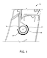
- FIG. 1 illustrates an exemplary heated roller shade system 10 that may be used in a vehicle (not shown).
- vehicle may be any type of vehicle, including but not limited to, an automobile, truck, car, van, aircraft, boat, or spacecraft.
- heated roller shade system 10 may be used in an over-wing exit door (not shown in FIG. 1 ) of an aircraft.
- Heated roller shade system 10 includes a roller 12 that includes a pretension spring (not shown), a roller housing 14, a shade 16, and a heating mechanism 17.
- Roller 12 is positioned in a cavity defined between an inner wall and an outer wall of a vehicle, such as between an inner wall and an outer wall of a door of the vehicle as described below. Roller 12 selectively extends shade 16 between an open position (not shown in FIG.
- heated roller shade system 10 When in the deployed position, heated roller shade system 10 facilitates reducing heat and/or light being transmitted between the external environment and the interior of the vehicle.
- heated roller shade system 10 When in the open position, heated roller shade system 10 defines a visual opening between an interior of the vehicle and the external environment (not shown in FIG. 1 ) through which passengers may view the external environment. In other implementations, heated roller shade system 10 does not include roller housing 14.
- shade 16 is fabricated from a fiberglass fiber that is embedded into a polyvinyl chloride (PVC) casing. Further in the exemplary implementation, shade 16 is coated with a layer of aluminum-based pigment. In other implementations, shade 16 may be fabricated from any material that enables shade 16 to operate as described herein.
- roller housing 14 is positioned about roller 12, such as substantially circumscribing roller 12, to facilitate shielding roller 12 and shade 16 from damage.
- roller housing 14 also includes an insulating material positioned between roller housing 14 and roller 12. Alternatively, insulating material may be positioned anywhere that enables roller housing 14 to insulate and shield roller 12 and shade 16 as described herein.
- heating mechanism 17 is thermally coupled to at least one of roller 12, roller housing 14, and shade 16 to selectively increase their respective temperatures. Moreover, in the exemplary implementation, heating mechanism 17 raises the temperature to a temperature that is above freezing to facilitate reducing ice buildup in and around heated roller shade system 10.
- heating mechanism 17 is at least one of a resistive heating mechanism (not shown in FIG. 1 ), an inductive heating mechanism (not shown in FIG. 1 ), a thermo-electric heating mechanism (not shown in FIG. 1 ), and/or an air gap heating mechanism (not shown in FIG. 1 ).
- heating mechanism 17 may be any heating device that that enables heating mechanism 17 to operate as described herein.
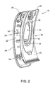
- FIG. 2 illustrates an exemplary over-wing exit door 19 in which heated roller shade system 10 operates.
- over-wing exit door 19 includes a hull 20 and a cabin wall 25.
- Hull 20 can be considered an outer wall of door 19
- cabin wall 25 can be considered an inner wall of door 19 such that shade system 10 is positioned between the inner wall and the outer wall of door 19.
- Hull 20 includes an inner hull surface 22 and an outer hull surface 24, and cabin wall 25 includes an outer cabin wall 28 and an inner cabin wall 30.
- Heated roller shade system 10 is positioned within a cavity 18 defined between hull 20 and cabin wall 25, and more specifically between inner hull surface 22 and outer cabin wall 28.
- Heated roller shade system 10 facilitates selectively obscuring a window 32 by extending shade 16 from a fully open position 34 to a fully deployed position 35 or to any position between these two positions.
- a passenger moves shade 16 toward fully deployed position 35 to obscure window 32 to facilitate reducing light and/or heat entering cabin 36 from external environment 38 as needed by the passenger.
- shade 16 is selectively retracted toward fully open position 34 by a passenger to define a visual opening that allows light and/or heat to pass through window 32 from external environment 38.
- heated roller shade system 10 retracts shade 16 in response to an emergency to allow viewing of exit conditions prior to utilizing over-wing exit door 19. Alternatively, shade 16 may be retracted in response to any other event and/or situation as needed by the passenger.
- Reduced temperatures i.e., temperatures at or below freezing temperatures, from external environment 38 induce freezing temperatures on outer hull surface 24.
- the freezing temperature propagates through cavity 18 toward cabin 36 by means of thermal conduction and/or convection.
- cabin 36 may be heated to maintain passenger comfort; cavity 18 is sealed from cabin 36 by cabin wall 25. Therefore, the temperature inside cavity 18 may be reduced to be at or below the freezing temperatures associated with external environment 38.
- any moisture inside cavity 18, i.e. from humid climates may permeate shade 16 and surround roller 12 and/or roller housing 14.
- heating mechanism 17 (shown in FIG. 1 ) provides heat to at least one of roller 12, roller housing 14, and shade 16.
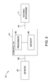
- FIG. 3 illustrates a block diagram of an exemplary heating control system 41 that may be used to control heating mechanism 17.
- Heating control system 41 includes heating mechanism 17, a sensor 40, a sensor wire 42, a controller 44, and a power line 50.
- heating control system 41 activates and deactivates heating mechanism 17 to facilitate selectively increasing the temperature of roller 12 (shown in FIG. 1 ), roller housing 14 (shown in FIG. 1 ), and/or shade 16 (shown in FIG. 1 ). Further in the exemplary implementation, heating control system 41 controls heating mechanism 17 based on data received from sensor 40.
- sensor 40 measures at least one of a temperature, a humidity, and/or a time associated with heated roller shade system 10.
- sensor 40 is one of a thermocouple, thermistor, and an infrared sensor and measures temperature associated with roller 12, roller housing 14, and/or shade 16.
- sensor 40 transmits a signal to controller 44 with the data measured by sensor 40 through sensor wire 42.
- sensor 40 may communicate wirelessly with controller 44 through any suitable wireless communication method, including, e.g., without limitation, radio frequency (RF).
- heating control system 41 may include any number of sensors 40 that enable heating control system 41 to operate as described herein.
- controller 44 includes at least one processor 46 that is coupled to a memory device 48 for executing instructions.
- executable instructions are stored in memory device 48.
- controller 44 performs one or more operations described herein by executing the executable instructions stored in memory device 48.
- processor 46 may be programmed by encoding an operation as one or more executable instructions in memory device 48 and by providing the executable instructions from memory device 48 to processor 46 for execution.
- Processor 46 may include one or more processing units (e.g., in a multi-core configuration). Further, processor 46 may be implemented using one or more heterogeneous processor systems in which a main processor is present with secondary processors on a single chip. In another illustrative example, processor 46 may be a symmetric multi-processor system containing multiple processors of the same type. Further, processor 46 may be implemented using any suitable programmable circuit including one or more systems and microcontrollers, microprocessors, reduced instruction set circuits (RISC), application specific integrated circuits (ASIC), programmable logic circuits, field programmable gate arrays (FPGA), and any other circuit capable of executing the functions described herein.
- RISC reduced instruction set circuits
- ASIC application specific integrated circuits
- FPGA field programmable gate arrays
- memory device 48 is one or more devices that enable information, such as executable instructions and/or other data, to be stored and retrieved.
- Memory device 48 may include one or more computer readable media, such as, without limitation, dynamic random access memory (DRAM), static random access memory (SRAM), a solid state disk, and/or a hard disk.
- Memory device 48 may be configured to store, without limitation, application source code, application object code, configuration data, predefined threshold settings, and/or any other type of data.
- Controller 44 controls heating mechanism 17 based on the data received from sensor 40, and based on a current status of heating mechanism 17. More specifically, in the exemplary implementation, memory device 48 contains a current status of heating mechanism 17, an activation threshold, and a deactivation threshold. The current status of heating mechanism 17 is indicative of whether or not heating mechanism 17 is currently active and providing heat to roller 12, roller housing 14, and/or shade 16.
- the activation threshold defines a value of a parameter, e.g., without limitation, temperature, humidity, and/or time, at which heating mechanism 17 is activated. In one implementation, the activation threshold is a predefined temperature value, for example, a near-freezing temperature, where, when the temperature around heated roller shade system 10 drops below the predefined temperature value, heating mechanism 17 is activated.
- the activation threshold is a predefined humidity level, such as a humidity that enables ice crystals to form, at which point heating mechanism 17 is activated.
- the activation threshold is a predefined point in time, e.g., without limitation, a time since take-off and/or a time since heating mechanism 17 was last activated or deactivated, at which point heating mechanism 17 is activated.
- the deactivation threshold defines a value of a parameter, e.g., without limitation temperature, humidity, and/or time at which heating mechanism 17 is deactivated.
- deactivating heating mechanism 17 based on the deactivation threshold facilitates preventing overheating of heated roller shade system 10.
- the activation threshold and the deactivation threshold are based on a plurality of parameters. Furthermore, in some implementations, the activation threshold and the deactivation threshold may be based on the same parameter such that they generate a range of temperatures, humidity levels, and/or time periods during which heating mechanism 17 is active. In the exemplary implementation, the activation threshold and the deactivation threshold may be set manually by an aircraft operator.
- Processor 46 receives data, e.g., without limitation, temperature data, humidity data, and time from sensor 40. Processor 46 also compares the data with one of the activation threshold and the deactivation threshold based on the current status of heating mechanism 17. For example, processor 46 compares the data with the activation threshold when heating mechanism 17 is deactivated, and compares the data with the deactivation threshold when heating mechanism 17 is activated. Processor 46 also activates and/or deactivates heating mechanism 17 based on the results of the comparison. In one implementation, for example, processor 46 activates heating mechanism 17 when the data indicates a current temperature below the activation threshold and heating mechanism 17 is currently inactive.
- data e.g., without limitation, temperature data, humidity data, and time from sensor 40.
- Processor 46 also compares the data with one of the activation threshold and the deactivation threshold based on the current status of heating mechanism 17. For example, processor 46 compares the data with the activation threshold when heating mechanism 17 is deactivated, and compares the data with the deactivation threshold when heating
- processor 46 may deactivate heating mechanism 17 if the data indicates a temperature above the deactivation threshold and heating mechanism 17 is currently activated.
- processor 46 may be programmed to activate and/or deactivate heating mechanism 17 in any manner that enables heating control system 41 to function as described herein.
- controller 44 may activate and/or deactivate heating mechanism 17 by controlling the flow of power via power line 50 to heating mechanism 17.
- controller 44 may be electrically coupled to a switch
- controller 44 controls an amount of power provided to heating mechanism 17, e.g., without limitation, using a variable current controlling device.
- controller 44 transmits a signal to heating mechanism 17 instructing heating mechanism 17 to activate heating and/or deactivate heating.
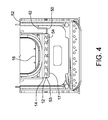
- FIG. 4 is an inboard facing view of an over-wing exit door 19 (shown in FIG. 2 ) including heated roller shade system 10 (shown in FIG. 1 ) having a resistive heating mechanism 54.
- heating mechanism 17 is coupled to a power source 52, such as a conventional door heater or other power in the door, and includes a heating blanket 53 that includes at least one resistive heating mechanism 54.
- heating blanket 53 may be coupled to roller housing 14. Alternatively, heating blanket 53 may be positioned anywhere that enables heating blanket 53 to function as described herein.
- Resistive heating mechanism 54 is coupled to power source 52 via power line 50. Power line 50 transmits power to resistive heating mechanism 54 which, in turn, induces a current in resistive heating mechanism 54.
- Resistive heating mechanism 54 generates heat through resistive losses. Heat generated in resistive heating mechanism 54 radiates to heating blanket 53, which, in turn, radiates heat to roller 12, roller housing 14, and/or shade 16.
- resistive heating mechanism 54 may be coupled to power source 52 through a power line 50 that is configured to heat cabin wall 25 (shown in FIG. 2 ). In alternate implementations, resistive heating mechanism 54 may be coupled directly to one of roller 12, roller housing 14, and shade 16 without heating blanket 53.
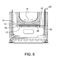
- FIG. 5 is an inboard facing view of an over-wing exit door 19 (shown in FIG. 2 ) including heated roller shade system 10 (shown in FIG. 1 ) having at least one inductive heating mechanism 56.
- heated roller shade system 10 also includes a receiving element (not shown).
- inductive heating mechanism 56 is coupled to power source 52, such as a conventional door heater or other power in the door, through power line 50.
- power line 50 transmits power to inductive heating mechanism 56 which, in turn, induces a current in at least one receiving element.
- the receiving element may be roller 12 and/or roller housing 14.
- the receiving element may any device thermally coupled to at least one of roller 12, roller housing 14, or shade 16 that enables inductive heating mechanism 56 to operate as described herein.
- the induced current causes the receiving element to radiate heat from the receiving element to at least one of roller 12, roller housing 14, and shade 16 to facilitate increasing the temperature of heated roller shade system 10.
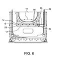
- FIG. 6 is an inboard facing view of an over-wing exit door 19 (shown in FIG. 2 ) including heated roller shade system 10 (shown in FIG. 1 ) having at least one thermo-electric heating mechanism 58.
- thermo-electric heating mechanism 58 is a thermo-electric ceramic.
- thermo-electric heating mechanism 58 may be any thermo-electric device that enables thermo-electric heating mechanism 58 to operate as described herein.
- heated roller shade system 10 includes a heating blanket 53 that includes at least one thermo-electric heating mechanism 58.
- heating blanket 53 may be coupled to roller housing 14.
- heating blanket 53 may be positioned anywhere that enables heating blanket 53 to function as described herein.
- thermo-electric heating mechanism 58 is coupled to power source 52, such as a conventional door heater or other power in the door, through power line 50.
- Thermo-electric heating mechanism 58 has a cold-side (not shown) and a hot-side (not shown) based on the applied current from power line 50.
- thermo-electric heating mechanism 58 is oriented such that the hot-side of the thermo-electric heating mechanism 58 is proximate to heated roller shade system 10, and the cold-side of the thermo-electric heating mechanism 58 is distal from heated roller shade system 10.
- power line 50 provides power to the at least one thermo-electric heating mechanism causing the hot-side to radiate heat to heating blanket 53, which, in turn, radiates heat to at least one of roller 12, roller housing 14, and shade 16.
- thermo-electric heating mechanism 58 may be coupled directly to one of roller 12, roller housing 14, and shade 16 without heating blanket 53.
- FIG. 7 is an inboard facing view of an over-wing exit door 19 (shown in FIG. 2 ) including heated roller shade system 10 (shown in FIG. 1 ) having an air-gap-based heating mechanism.
- heating mechanism 17 includes an air gap 60 and a valve 62.
- Air gap 60 extends from cavity 18 (shown in FIG. 2 ) through cabin wall 25 (shown in FIG. 2 ) to cabin 36 (shown in FIG. 2 ).
- air gap 60 extends through the inner wall (e.g., cabin wall 25).
- when valve 62 is open air flows from cavity 18 to cabin 36 and vice-versa through air gap 60.
- air within cabin 36 may be of a temperature higher than air within cavity 18, such that the transmission of air from cabin 36 to cavity 18 facilitates increasing the temperature of the air within cavity 18.
- the increased temperature of the air inside cavity 18 facilitates increasing the temperature in and around at least one of roller 12, roller housing 14, and shade 16.
- air-gap-based heating mechanism 17 may be in communication with controller 44 (shown in FIG. 3 ), such that controller 44 controls the opening and closing of valve 62 based on the temperature data measured by temperature sensor 40 (shown in FIG. 3 ).
- controller 44 controls the opening and closing of valve 62 based on the temperature data measured by temperature sensor 40 (shown in FIG. 3 ).
- valve 62 may be controlled in any manner that enables air-gap-based heating mechanism 17 to function as described herein.
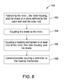
- FIG. 8 is an exemplary flowchart illustrating a method 100 for assembling a heated roller shade system 10.
- the method includes positioning 102 roller 12 (shown in FIG. 1 ) in a cavity 18 (shown in FIG. 2 ) defined by cabin wall 25 (shown in FIG. 2 ) and hull 20 (shown in FIG. 2 ).
- the method also includes coupling 104 shade 16 (shown in FIG. 1 ) to roller 12.
- Roller 12 is configured to selectively move shade 16 between fully deployed position 35 (shown in FIG. 2 ) and fully open position 34 (shown in FIG. 2 ).
- the method further includes coupling 106 heating mechanism 17 (shown in FIG. 1 ) to at least one of roller 12, roller housing 14 (shown in FIG. 1 ) and shade 16.
- Heating mechanism 17 facilitates increasing a temperature of at least one of roller 12, roller housing 14, and shade 16.
- coupling heating mechanism 17 to at least one of roller 12 and shade 16 includes thermally coupling at least one of a resistive heating mechanism 54 (shown in FIG. 4 ), an inductive heating mechanism 56 (shown in FIG. 5 ), a thermo-electric heating mechanism 58 (shown in FIG. 6 ), and an air-gap-based heating mechanism 17 having an air gap 60 (shown in FIG. 7 ) and a valve 62 (shown in FIG. 7 ) to at least one of roller 12, roller housing 14, and shade 16.
- the method further comprises communicatively coupling 108 controller 44 to heating mechanism 17.
- Controller 44 controls activating and/or deactivating heating mechanism 17 based on an activation threshold and a deactivation threshold.
- the above-described implementations disclose a durable and dependable heated roller shade system.
- the heated roller shade system uses a heating mechanism thermally coupled to at least one of the roller, the roller housing, and the shade to facilitate increasing the temperature of the roller shade system from a first temperature to a second temperature.
- the heated roller shade system described herein facilitates increasing the temperature in and around the roller shade system above a freezing temperature to facilitate preventing the buildup of ice in and around the roller shade system.
- the heated roller shade system thereby facilitates improving the dependability and durability of the roller and the shade.
- the heated roller shade system also contains controls to facilitate preventing overheating of the roller shade system.
- the heated roller shade system may also contain various heating mechanisms that may facilitate increasing the temperature in and around the roller and the shade, the various heating mechanisms having different power requirements, different weight aspects, and different overheating requirements.
- a technical effect of the systems and methods described herein includes at least one of: (a) receiving data indicating at least one of a current temperature, a current humidity, and a time associated with the heated roller shade system from a sensor; (b) comparing the data with an activation threshold; (c) activating a heating mechanism based on the comparison between the data and the activation threshold to facilitate increasing a temperature of at least one of the roller and the shade; (d) comparing the data with a deactivation threshold; and (e) deactivating the heating mechanism based on the comparison between the data and the deactivation threshold.
Landscapes
- Engineering & Computer Science (AREA)
- Aviation & Aerospace Engineering (AREA)
- Mechanical Engineering (AREA)
- Civil Engineering (AREA)
- Structural Engineering (AREA)
- Control Of Resistance Heating (AREA)
- Air-Conditioning For Vehicles (AREA)
- Drying Of Solid Materials (AREA)
- Operating, Guiding And Securing Of Roll- Type Closing Members (AREA)
Applications Claiming Priority (1)
| Application Number | Priority Date | Filing Date | Title |
|---|---|---|---|
| US14/012,383 US9957049B2 (en) | 2013-08-28 | 2013-08-28 | Retractable shade and method for assembling the same |
Publications (2)
| Publication Number | Publication Date |
|---|---|
| EP2845796A1 true EP2845796A1 (de) | 2015-03-11 |
| EP2845796B1 EP2845796B1 (de) | 2017-10-04 |
Family
ID=51398571
Family Applications (1)
| Application Number | Title | Priority Date | Filing Date |
|---|---|---|---|
| EP14182471.4A Not-in-force EP2845796B1 (de) | 2013-08-28 | 2014-08-27 | Einziehbare Jalousie und Montageverfahren dafür |
Country Status (5)
| Country | Link |
|---|---|
| US (1) | US9957049B2 (de) |
| EP (1) | EP2845796B1 (de) |
| BR (1) | BR102014020833A2 (de) |
| CA (1) | CA2851863C (de) |
| ES (1) | ES2654811T3 (de) |
Cited By (1)
| Publication number | Priority date | Publication date | Assignee | Title |
|---|---|---|---|---|
| US12280865B2 (en) | 2022-08-22 | 2025-04-22 | Textron Innovations Inc. | Window roller shade and dimming pane |
Families Citing this family (3)
| Publication number | Priority date | Publication date | Assignee | Title |
|---|---|---|---|---|
| DE102011114643B4 (de) * | 2011-09-30 | 2016-03-24 | Airbus Operations Gmbh | Betätigungsvorrichtung zum Öffnen einer Notausgangsklappe einer Cockpittür |
| JP7101452B2 (ja) * | 2016-07-19 | 2022-07-15 | ナブテスコ株式会社 | 電動アクチュエータ駆動制御装置及び航空機 |
| DE102018221013B4 (de) | 2018-12-05 | 2024-09-12 | Bos Gmbh & Co. Kg | Rollovorrichtung für einen Fahrzeuginnenraum und Rollowelle hierfür |
Citations (5)
| Publication number | Priority date | Publication date | Assignee | Title |
|---|---|---|---|---|
| DE2704248A1 (de) * | 1977-02-02 | 1978-08-03 | Wilhelm Bottermann | Einrollbarer wand- bzw. dekorteppich |
| US4399347A (en) * | 1980-06-28 | 1983-08-16 | Firma Carl Freudenberg | Device for attachment to motor vehicle windows to prevent fogging or icing |
| JPH07223432A (ja) * | 1994-02-07 | 1995-08-22 | Toyo Seimitsu Kogyo Kk | 自動車用日除け兼用霜取りスクリーン |
| EP1600316A1 (de) * | 2004-05-27 | 2005-11-30 | Adams Rite Aerospace, Inc. | Vorrichtung zur Betätigung einer Fenstersonnenblende |
| US20110006050A1 (en) * | 2009-07-13 | 2011-01-13 | Joseph Patrick Nee | Thermally Heated Collapsible Sun shade |
Family Cites Families (19)
| Publication number | Priority date | Publication date | Assignee | Title |
|---|---|---|---|---|
| US2660659A (en) * | 1949-08-11 | 1953-11-24 | Asea Ab | Heated roller blind |
| US3217137A (en) * | 1963-09-03 | 1965-11-09 | Dorothea M Weitzner | Heated towel rack and hanger |
| GB1432862A (en) | 1973-01-26 | 1976-04-22 | Plessey Co Ltd | Windscreen-heating arrangements |
| US3982092A (en) * | 1974-09-06 | 1976-09-21 | Libbey-Owens-Ford Company | Electrically heated zoned window systems |
| NO760249L (no) * | 1976-01-27 | 1977-07-28 | Hans Brattrud | Anordning til oppvarming av en rullegardin eller lignende. |
| US4275645A (en) * | 1978-07-10 | 1981-06-30 | Expertise Assistance Inc. | Closure for service opening |
| US4942287A (en) * | 1989-06-19 | 1990-07-17 | Paul Walker | Linoleum roll heater assembly |
| US5089912A (en) * | 1990-09-28 | 1992-02-18 | General Motors Corporation | Retractable antiglare shield for exterior rear view mirrors |
| US5544690A (en) * | 1994-05-11 | 1996-08-13 | Magro; Sebastian | Roll-up door provided with thermal protection means and a direct drive gearing arrangement |
| DE4431110C1 (de) * | 1994-09-01 | 1996-04-04 | Daimler Benz Ag | Rollo für eine Scheibe eines Kraftfahrzeugs |
| US6713733B2 (en) | 1999-05-11 | 2004-03-30 | Thermosoft International Corporation | Textile heater with continuous temperature sensing and hot spot detection |
| US6768086B2 (en) * | 2002-07-08 | 2004-07-27 | Sunbeam Products, Inc. | Temperature sensor for a warming blanket |
| CA2502339A1 (en) * | 2005-03-24 | 2006-09-24 | Vincent Chau | Remotely controlled automatic vehicle cover |
| US7401840B2 (en) * | 2006-05-09 | 2008-07-22 | Gm Global Technology Operations, Inc. | Window shade |
| US7718923B1 (en) | 2007-02-09 | 2010-05-18 | Hansen Scott P | Defrosting windshield sunshade panel |
| DE102008047508C5 (de) * | 2008-09-12 | 2021-12-23 | Bos Gmbh & Co. Kg | Rollosystem |
| US8646828B2 (en) * | 2010-08-30 | 2014-02-11 | Honda Motor Co., Ltd. | Sunshade assembly for a vehicle |
| DE102010063595B4 (de) * | 2010-12-20 | 2016-11-03 | Bos Gmbh & Co. Kg | Abdecksystem und Kraftfahrzeug mit einem Abdecksystem |
| US8663535B2 (en) * | 2011-06-17 | 2014-03-04 | Honda Motor Co., Ltd. | Integrated sunshade design |
-
2013
- 2013-08-28 US US14/012,383 patent/US9957049B2/en not_active Expired - Fee Related
-
2014
- 2014-05-14 CA CA2851863A patent/CA2851863C/en not_active Expired - Fee Related
- 2014-08-25 BR BR102014020833A patent/BR102014020833A2/pt active Search and Examination
- 2014-08-27 ES ES14182471.4T patent/ES2654811T3/es active Active
- 2014-08-27 EP EP14182471.4A patent/EP2845796B1/de not_active Not-in-force
Patent Citations (5)
| Publication number | Priority date | Publication date | Assignee | Title |
|---|---|---|---|---|
| DE2704248A1 (de) * | 1977-02-02 | 1978-08-03 | Wilhelm Bottermann | Einrollbarer wand- bzw. dekorteppich |
| US4399347A (en) * | 1980-06-28 | 1983-08-16 | Firma Carl Freudenberg | Device for attachment to motor vehicle windows to prevent fogging or icing |
| JPH07223432A (ja) * | 1994-02-07 | 1995-08-22 | Toyo Seimitsu Kogyo Kk | 自動車用日除け兼用霜取りスクリーン |
| EP1600316A1 (de) * | 2004-05-27 | 2005-11-30 | Adams Rite Aerospace, Inc. | Vorrichtung zur Betätigung einer Fenstersonnenblende |
| US20110006050A1 (en) * | 2009-07-13 | 2011-01-13 | Joseph Patrick Nee | Thermally Heated Collapsible Sun shade |
Cited By (1)
| Publication number | Priority date | Publication date | Assignee | Title |
|---|---|---|---|---|
| US12280865B2 (en) | 2022-08-22 | 2025-04-22 | Textron Innovations Inc. | Window roller shade and dimming pane |
Also Published As
| Publication number | Publication date |
|---|---|
| US20150059988A1 (en) | 2015-03-05 |
| ES2654811T3 (es) | 2018-02-15 |
| US9957049B2 (en) | 2018-05-01 |
| CA2851863C (en) | 2016-07-05 |
| BR102014020833A2 (pt) | 2015-09-22 |
| CA2851863A1 (en) | 2015-02-28 |
| EP2845796B1 (de) | 2017-10-04 |
Similar Documents
| Publication | Publication Date | Title |
|---|---|---|
| CA2851863C (en) | Retractable shade and method for assembling the same | |
| US10590677B2 (en) | Heated mechanism for deployable exterior door handle for a vehicle | |
| CN107074123B (zh) | 用于电动车辆或混合动力车辆的空气调节方法和空调系统 | |
| US8336822B2 (en) | Apparatus for providing variable thermal insulation for an aircraft | |
| CN107635820B (zh) | 充电设备和用于运行充电设备的方法 | |
| US9409649B2 (en) | Detection of icing conditions on an aircraft | |
| RU2690026C1 (ru) | Система мониторинга оборудования летательного аппарата | |
| EP2465768B1 (de) | Verfahren und Vorrichtung zur Luftstromsteuerung in einem Flugzeugseitenwandvolumen | |
| US20160068044A1 (en) | Radiant heater air-conditioning system | |
| BR112015031474B1 (pt) | Método e sistema para anticongelação/descongelação de um equipamento de aeronave, e, porta de aeronaves e aeronave equipada com um sistema anticongelação/descongelação. | |
| EP2500541A1 (de) | Kühlsystem für einen verbrennungsmotor sowie fehlerbestimmungsverfahren für das kühlsystem für einen verbrennungsmotor | |
| US9290118B2 (en) | Heated flight attendant jumpseats for commercial airplane applications | |
| EP2743534B1 (de) | System und Verfahren zur Bestimmung einer adaptiven Schwelle für eine Zeitdauer zwischen aufeinander folgenden Flügen eines Flugzeugs. | |
| US20190126082A1 (en) | Aircraft fire extinguishing with heated tubing | |
| US20170174349A1 (en) | Ice protection systems | |
| CN106774505A (zh) | 无人机电机散热方法及装置 | |
| KR101527052B1 (ko) | 자동차의 실내온도 통합제어 방법 | |
| US20190057560A1 (en) | Method and system for predicting wing anti-ice failure | |
| US11390387B2 (en) | De-icing system and method | |
| WO2019137088A1 (zh) | 自适应运舱空调系统与其控制方法及具有该系统的移动载具 | |
| CN105644791B (zh) | 结冰探测系统及具有该结冰系统的飞行器 | |
| US9868535B2 (en) | Method and a system for treating ice for an aircraft windshield | |
| CN108945487B (zh) | 飞机及其发动机fadec供电控制装置 | |
| US20090289147A1 (en) | Method of collecting information relating to a movable airfoil surface of an aircraft | |
| US20180288832A1 (en) | Heating Electronic Dimmable Windows |
Legal Events
| Date | Code | Title | Description |
|---|---|---|---|
| 17P | Request for examination filed |
Effective date: 20140827 |
|
| AK | Designated contracting states |
Kind code of ref document: A1 Designated state(s): AL AT BE BG CH CY CZ DE DK EE ES FI FR GB GR HR HU IE IS IT LI LT LU LV MC MK MT NL NO PL PT RO RS SE SI SK SM TR |
|
| AX | Request for extension of the european patent |
Extension state: BA ME |
|
| PUAI | Public reference made under article 153(3) epc to a published international application that has entered the european phase |
Free format text: ORIGINAL CODE: 0009012 |
|
| R17P | Request for examination filed (corrected) |
Effective date: 20150902 |
|
| RBV | Designated contracting states (corrected) |
Designated state(s): AL AT BE BG CH CY CZ DE DK EE ES FI FR GB GR HR HU IE IS IT LI LT LU LV MC MK MT NL NO PL PT RO RS SE SI SK SM TR |
|
| GRAP | Despatch of communication of intention to grant a patent |
Free format text: ORIGINAL CODE: EPIDOSNIGR1 |
|
| INTG | Intention to grant announced |
Effective date: 20170405 |
|
| GRAS | Grant fee paid |
Free format text: ORIGINAL CODE: EPIDOSNIGR3 |
|
| GRAA | (expected) grant |
Free format text: ORIGINAL CODE: 0009210 |
|
| AK | Designated contracting states |
Kind code of ref document: B1 Designated state(s): AL AT BE BG CH CY CZ DE DK EE ES FI FR GB GR HR HU IE IS IT LI LT LU LV MC MK MT NL NO PL PT RO RS SE SI SK SM TR |
|
| REG | Reference to a national code |
Ref country code: GB Ref legal event code: FG4D |
|
| REG | Reference to a national code |
Ref country code: CH Ref legal event code: EP |
|
| REG | Reference to a national code |
Ref country code: AT Ref legal event code: REF Ref document number: 933739 Country of ref document: AT Kind code of ref document: T Effective date: 20171015 |
|
| REG | Reference to a national code |
Ref country code: IE Ref legal event code: FG4D |
|
| REG | Reference to a national code |
Ref country code: DE Ref legal event code: R096 Ref document number: 602014015301 Country of ref document: DE |
|
| REG | Reference to a national code |
Ref country code: NL Ref legal event code: MP Effective date: 20171004 |
|
| REG | Reference to a national code |
Ref country code: ES Ref legal event code: FG2A Ref document number: 2654811 Country of ref document: ES Kind code of ref document: T3 Effective date: 20180215 |
|
| REG | Reference to a national code |
Ref country code: LT Ref legal event code: MG4D |
|
| REG | Reference to a national code |
Ref country code: AT Ref legal event code: MK05 Ref document number: 933739 Country of ref document: AT Kind code of ref document: T Effective date: 20171004 |
|
| PG25 | Lapsed in a contracting state [announced via postgrant information from national office to epo] |
Ref country code: NL Free format text: LAPSE BECAUSE OF FAILURE TO SUBMIT A TRANSLATION OF THE DESCRIPTION OR TO PAY THE FEE WITHIN THE PRESCRIBED TIME-LIMIT Effective date: 20171004 |
|
| PG25 | Lapsed in a contracting state [announced via postgrant information from national office to epo] |
Ref country code: LT Free format text: LAPSE BECAUSE OF FAILURE TO SUBMIT A TRANSLATION OF THE DESCRIPTION OR TO PAY THE FEE WITHIN THE PRESCRIBED TIME-LIMIT Effective date: 20171004 Ref country code: NO Free format text: LAPSE BECAUSE OF FAILURE TO SUBMIT A TRANSLATION OF THE DESCRIPTION OR TO PAY THE FEE WITHIN THE PRESCRIBED TIME-LIMIT Effective date: 20180104 Ref country code: SE Free format text: LAPSE BECAUSE OF FAILURE TO SUBMIT A TRANSLATION OF THE DESCRIPTION OR TO PAY THE FEE WITHIN THE PRESCRIBED TIME-LIMIT Effective date: 20171004 Ref country code: FI Free format text: LAPSE BECAUSE OF FAILURE TO SUBMIT A TRANSLATION OF THE DESCRIPTION OR TO PAY THE FEE WITHIN THE PRESCRIBED TIME-LIMIT Effective date: 20171004 |
|
| PG25 | Lapsed in a contracting state [announced via postgrant information from national office to epo] |
Ref country code: RS Free format text: LAPSE BECAUSE OF FAILURE TO SUBMIT A TRANSLATION OF THE DESCRIPTION OR TO PAY THE FEE WITHIN THE PRESCRIBED TIME-LIMIT Effective date: 20171004 Ref country code: GR Free format text: LAPSE BECAUSE OF FAILURE TO SUBMIT A TRANSLATION OF THE DESCRIPTION OR TO PAY THE FEE WITHIN THE PRESCRIBED TIME-LIMIT Effective date: 20180105 Ref country code: LV Free format text: LAPSE BECAUSE OF FAILURE TO SUBMIT A TRANSLATION OF THE DESCRIPTION OR TO PAY THE FEE WITHIN THE PRESCRIBED TIME-LIMIT Effective date: 20171004 Ref country code: AT Free format text: LAPSE BECAUSE OF FAILURE TO SUBMIT A TRANSLATION OF THE DESCRIPTION OR TO PAY THE FEE WITHIN THE PRESCRIBED TIME-LIMIT Effective date: 20171004 Ref country code: IS Free format text: LAPSE BECAUSE OF FAILURE TO SUBMIT A TRANSLATION OF THE DESCRIPTION OR TO PAY THE FEE WITHIN THE PRESCRIBED TIME-LIMIT Effective date: 20180204 Ref country code: BG Free format text: LAPSE BECAUSE OF FAILURE TO SUBMIT A TRANSLATION OF THE DESCRIPTION OR TO PAY THE FEE WITHIN THE PRESCRIBED TIME-LIMIT Effective date: 20180104 Ref country code: HR Free format text: LAPSE BECAUSE OF FAILURE TO SUBMIT A TRANSLATION OF THE DESCRIPTION OR TO PAY THE FEE WITHIN THE PRESCRIBED TIME-LIMIT Effective date: 20171004 |
|
| REG | Reference to a national code |
Ref country code: DE Ref legal event code: R097 Ref document number: 602014015301 Country of ref document: DE |
|
| PG25 | Lapsed in a contracting state [announced via postgrant information from national office to epo] |
Ref country code: DK Free format text: LAPSE BECAUSE OF FAILURE TO SUBMIT A TRANSLATION OF THE DESCRIPTION OR TO PAY THE FEE WITHIN THE PRESCRIBED TIME-LIMIT Effective date: 20171004 Ref country code: SK Free format text: LAPSE BECAUSE OF FAILURE TO SUBMIT A TRANSLATION OF THE DESCRIPTION OR TO PAY THE FEE WITHIN THE PRESCRIBED TIME-LIMIT Effective date: 20171004 Ref country code: CZ Free format text: LAPSE BECAUSE OF FAILURE TO SUBMIT A TRANSLATION OF THE DESCRIPTION OR TO PAY THE FEE WITHIN THE PRESCRIBED TIME-LIMIT Effective date: 20171004 Ref country code: EE Free format text: LAPSE BECAUSE OF FAILURE TO SUBMIT A TRANSLATION OF THE DESCRIPTION OR TO PAY THE FEE WITHIN THE PRESCRIBED TIME-LIMIT Effective date: 20171004 |
|
| PLBE | No opposition filed within time limit |
Free format text: ORIGINAL CODE: 0009261 |
|
| STAA | Information on the status of an ep patent application or granted ep patent |
Free format text: STATUS: NO OPPOSITION FILED WITHIN TIME LIMIT |
|
| REG | Reference to a national code |
Ref country code: FR Ref legal event code: PLFP Year of fee payment: 5 |
|
| PG25 | Lapsed in a contracting state [announced via postgrant information from national office to epo] |
Ref country code: PL Free format text: LAPSE BECAUSE OF FAILURE TO SUBMIT A TRANSLATION OF THE DESCRIPTION OR TO PAY THE FEE WITHIN THE PRESCRIBED TIME-LIMIT Effective date: 20171004 Ref country code: RO Free format text: LAPSE BECAUSE OF FAILURE TO SUBMIT A TRANSLATION OF THE DESCRIPTION OR TO PAY THE FEE WITHIN THE PRESCRIBED TIME-LIMIT Effective date: 20171004 Ref country code: SM Free format text: LAPSE BECAUSE OF FAILURE TO SUBMIT A TRANSLATION OF THE DESCRIPTION OR TO PAY THE FEE WITHIN THE PRESCRIBED TIME-LIMIT Effective date: 20171004 |
|
| 26N | No opposition filed |
Effective date: 20180705 |
|
| PG25 | Lapsed in a contracting state [announced via postgrant information from national office to epo] |
Ref country code: SI Free format text: LAPSE BECAUSE OF FAILURE TO SUBMIT A TRANSLATION OF THE DESCRIPTION OR TO PAY THE FEE WITHIN THE PRESCRIBED TIME-LIMIT Effective date: 20171004 |
|
| PG25 | Lapsed in a contracting state [announced via postgrant information from national office to epo] |
Ref country code: MC Free format text: LAPSE BECAUSE OF FAILURE TO SUBMIT A TRANSLATION OF THE DESCRIPTION OR TO PAY THE FEE WITHIN THE PRESCRIBED TIME-LIMIT Effective date: 20171004 |
|
| REG | Reference to a national code |
Ref country code: CH Ref legal event code: PL |
|
| GBPC | Gb: european patent ceased through non-payment of renewal fee |
Effective date: 20180827 |
|
| PG25 | Lapsed in a contracting state [announced via postgrant information from national office to epo] |
Ref country code: LI Free format text: LAPSE BECAUSE OF NON-PAYMENT OF DUE FEES Effective date: 20180831 Ref country code: CH Free format text: LAPSE BECAUSE OF NON-PAYMENT OF DUE FEES Effective date: 20180831 Ref country code: LU Free format text: LAPSE BECAUSE OF NON-PAYMENT OF DUE FEES Effective date: 20180827 |
|
| REG | Reference to a national code |
Ref country code: BE Ref legal event code: MM Effective date: 20180831 |
|
| PG25 | Lapsed in a contracting state [announced via postgrant information from national office to epo] |
Ref country code: BE Free format text: LAPSE BECAUSE OF NON-PAYMENT OF DUE FEES Effective date: 20180831 |
|
| PG25 | Lapsed in a contracting state [announced via postgrant information from national office to epo] |
Ref country code: GB Free format text: LAPSE BECAUSE OF NON-PAYMENT OF DUE FEES Effective date: 20180827 |
|
| PG25 | Lapsed in a contracting state [announced via postgrant information from national office to epo] |
Ref country code: MT Free format text: LAPSE BECAUSE OF NON-PAYMENT OF DUE FEES Effective date: 20180827 |
|
| PG25 | Lapsed in a contracting state [announced via postgrant information from national office to epo] |
Ref country code: TR Free format text: LAPSE BECAUSE OF FAILURE TO SUBMIT A TRANSLATION OF THE DESCRIPTION OR TO PAY THE FEE WITHIN THE PRESCRIBED TIME-LIMIT Effective date: 20171004 |
|
| PG25 | Lapsed in a contracting state [announced via postgrant information from national office to epo] |
Ref country code: HU Free format text: LAPSE BECAUSE OF FAILURE TO SUBMIT A TRANSLATION OF THE DESCRIPTION OR TO PAY THE FEE WITHIN THE PRESCRIBED TIME-LIMIT; INVALID AB INITIO Effective date: 20140827 Ref country code: PT Free format text: LAPSE BECAUSE OF FAILURE TO SUBMIT A TRANSLATION OF THE DESCRIPTION OR TO PAY THE FEE WITHIN THE PRESCRIBED TIME-LIMIT Effective date: 20171004 |
|
| PG25 | Lapsed in a contracting state [announced via postgrant information from national office to epo] |
Ref country code: IE Free format text: LAPSE BECAUSE OF NON-PAYMENT OF DUE FEES Effective date: 20180827 Ref country code: CY Free format text: LAPSE BECAUSE OF FAILURE TO SUBMIT A TRANSLATION OF THE DESCRIPTION OR TO PAY THE FEE WITHIN THE PRESCRIBED TIME-LIMIT Effective date: 20171004 Ref country code: MK Free format text: LAPSE BECAUSE OF NON-PAYMENT OF DUE FEES Effective date: 20171004 |
|
| PG25 | Lapsed in a contracting state [announced via postgrant information from national office to epo] |
Ref country code: AL Free format text: LAPSE BECAUSE OF FAILURE TO SUBMIT A TRANSLATION OF THE DESCRIPTION OR TO PAY THE FEE WITHIN THE PRESCRIBED TIME-LIMIT Effective date: 20171004 |
|
| PGFP | Annual fee paid to national office [announced via postgrant information from national office to epo] |
Ref country code: FR Payment date: 20210825 Year of fee payment: 8 Ref country code: IT Payment date: 20210820 Year of fee payment: 8 |
|
| PGFP | Annual fee paid to national office [announced via postgrant information from national office to epo] |
Ref country code: ES Payment date: 20210901 Year of fee payment: 8 Ref country code: DE Payment date: 20210827 Year of fee payment: 8 |
|
| REG | Reference to a national code |
Ref country code: DE Ref legal event code: R119 Ref document number: 602014015301 Country of ref document: DE |
|
| PG25 | Lapsed in a contracting state [announced via postgrant information from national office to epo] |
Ref country code: IT Free format text: LAPSE BECAUSE OF NON-PAYMENT OF DUE FEES Effective date: 20220827 Ref country code: FR Free format text: LAPSE BECAUSE OF NON-PAYMENT OF DUE FEES Effective date: 20220831 Ref country code: DE Free format text: LAPSE BECAUSE OF NON-PAYMENT OF DUE FEES Effective date: 20230301 |
|
| REG | Reference to a national code |
Ref country code: ES Ref legal event code: FD2A Effective date: 20230929 |
|
| PG25 | Lapsed in a contracting state [announced via postgrant information from national office to epo] |
Ref country code: ES Free format text: LAPSE BECAUSE OF NON-PAYMENT OF DUE FEES Effective date: 20220828 |