EP2845749A1 - Tire-reinforcing steel cord and radial tire using the same - Google Patents
Tire-reinforcing steel cord and radial tire using the same Download PDFInfo
- Publication number
- EP2845749A1 EP2845749A1 EP14163669.6A EP14163669A EP2845749A1 EP 2845749 A1 EP2845749 A1 EP 2845749A1 EP 14163669 A EP14163669 A EP 14163669A EP 2845749 A1 EP2845749 A1 EP 2845749A1
- Authority
- EP
- European Patent Office
- Prior art keywords
- tire
- layer core
- steel cord
- filaments
- reinforcing steel
- Prior art date
- Legal status (The legal status is an assumption and is not a legal conclusion. Google has not performed a legal analysis and makes no representation as to the accuracy of the status listed.)
- Granted
Links
Images


Classifications
-
- D—TEXTILES; PAPER
- D07—ROPES; CABLES OTHER THAN ELECTRIC
- D07B—ROPES OR CABLES IN GENERAL
- D07B1/00—Constructional features of ropes or cables
- D07B1/06—Ropes or cables built-up from metal wires, e.g. of section wires around a hemp core
-
- B—PERFORMING OPERATIONS; TRANSPORTING
- B60—VEHICLES IN GENERAL
- B60C—VEHICLE TYRES; TYRE INFLATION; TYRE CHANGING; CONNECTING VALVES TO INFLATABLE ELASTIC BODIES IN GENERAL; DEVICES OR ARRANGEMENTS RELATED TO TYRES
- B60C9/00—Reinforcements or ply arrangement of pneumatic tyres
- B60C9/0007—Reinforcements made of metallic elements, e.g. cords, yarns, filaments or fibres made from metal
-
- B—PERFORMING OPERATIONS; TRANSPORTING
- B60—VEHICLES IN GENERAL
- B60C—VEHICLE TYRES; TYRE INFLATION; TYRE CHANGING; CONNECTING VALVES TO INFLATABLE ELASTIC BODIES IN GENERAL; DEVICES OR ARRANGEMENTS RELATED TO TYRES
- B60C9/00—Reinforcements or ply arrangement of pneumatic tyres
-
- B—PERFORMING OPERATIONS; TRANSPORTING
- B60—VEHICLES IN GENERAL
- B60C—VEHICLE TYRES; TYRE INFLATION; TYRE CHANGING; CONNECTING VALVES TO INFLATABLE ELASTIC BODIES IN GENERAL; DEVICES OR ARRANGEMENTS RELATED TO TYRES
- B60C9/00—Reinforcements or ply arrangement of pneumatic tyres
- B60C9/0057—Reinforcements comprising preshaped elements, e.g. undulated or zig-zag filaments
-
- D—TEXTILES; PAPER
- D02—YARNS; MECHANICAL FINISHING OF YARNS OR ROPES; WARPING OR BEAMING
- D02G—CRIMPING OR CURLING FIBRES, FILAMENTS, THREADS, OR YARNS; YARNS OR THREADS
- D02G3/00—Yarns or threads, e.g. fancy yarns; Processes or apparatus for the production thereof, not otherwise provided for
- D02G3/02—Yarns or threads characterised by the material or by the materials from which they are made
- D02G3/12—Threads containing metallic filaments or strips
-
- D—TEXTILES; PAPER
- D02—YARNS; MECHANICAL FINISHING OF YARNS OR ROPES; WARPING OR BEAMING
- D02G—CRIMPING OR CURLING FIBRES, FILAMENTS, THREADS, OR YARNS; YARNS OR THREADS
- D02G3/00—Yarns or threads, e.g. fancy yarns; Processes or apparatus for the production thereof, not otherwise provided for
- D02G3/44—Yarns or threads characterised by the purpose for which they are designed
- D02G3/48—Tyre cords
-
- D—TEXTILES; PAPER
- D07—ROPES; CABLES OTHER THAN ELECTRIC
- D07B—ROPES OR CABLES IN GENERAL
- D07B1/00—Constructional features of ropes or cables
- D07B1/06—Ropes or cables built-up from metal wires, e.g. of section wires around a hemp core
- D07B1/0606—Reinforcing cords for rubber or plastic articles
- D07B1/0613—Reinforcing cords for rubber or plastic articles the reinforcing cords being characterised by the rope configuration
-
- D—TEXTILES; PAPER
- D07—ROPES; CABLES OTHER THAN ELECTRIC
- D07B—ROPES OR CABLES IN GENERAL
- D07B1/00—Constructional features of ropes or cables
- D07B1/06—Ropes or cables built-up from metal wires, e.g. of section wires around a hemp core
- D07B1/0606—Reinforcing cords for rubber or plastic articles
- D07B1/062—Reinforcing cords for rubber or plastic articles the reinforcing cords being characterised by the strand configuration
- D07B1/0633—Reinforcing cords for rubber or plastic articles the reinforcing cords being characterised by the strand configuration having a multiple-layer configuration
-
- B—PERFORMING OPERATIONS; TRANSPORTING
- B60—VEHICLES IN GENERAL
- B60C—VEHICLE TYRES; TYRE INFLATION; TYRE CHANGING; CONNECTING VALVES TO INFLATABLE ELASTIC BODIES IN GENERAL; DEVICES OR ARRANGEMENTS RELATED TO TYRES
- B60C9/00—Reinforcements or ply arrangement of pneumatic tyres
- B60C9/0007—Reinforcements made of metallic elements, e.g. cords, yarns, filaments or fibres made from metal
- B60C2009/0014—Surface treatments of steel cords
-
- B—PERFORMING OPERATIONS; TRANSPORTING
- B60—VEHICLES IN GENERAL
- B60C—VEHICLE TYRES; TYRE INFLATION; TYRE CHANGING; CONNECTING VALVES TO INFLATABLE ELASTIC BODIES IN GENERAL; DEVICES OR ARRANGEMENTS RELATED TO TYRES
- B60C9/00—Reinforcements or ply arrangement of pneumatic tyres
- B60C9/0007—Reinforcements made of metallic elements, e.g. cords, yarns, filaments or fibres made from metal
- B60C2009/0021—Coating rubbers for steel cords
-
- B—PERFORMING OPERATIONS; TRANSPORTING
- B60—VEHICLES IN GENERAL
- B60C—VEHICLE TYRES; TYRE INFLATION; TYRE CHANGING; CONNECTING VALVES TO INFLATABLE ELASTIC BODIES IN GENERAL; DEVICES OR ARRANGEMENTS RELATED TO TYRES
- B60C9/00—Reinforcements or ply arrangement of pneumatic tyres
- B60C2009/0071—Reinforcements or ply arrangement of pneumatic tyres characterised by special physical properties of the reinforcements
- B60C2009/0092—Twist structure
-
- B—PERFORMING OPERATIONS; TRANSPORTING
- B60—VEHICLES IN GENERAL
- B60C—VEHICLE TYRES; TYRE INFLATION; TYRE CHANGING; CONNECTING VALVES TO INFLATABLE ELASTIC BODIES IN GENERAL; DEVICES OR ARRANGEMENTS RELATED TO TYRES
- B60C9/00—Reinforcements or ply arrangement of pneumatic tyres
- B60C9/02—Carcasses
- B60C9/04—Carcasses the reinforcing cords of each carcass ply arranged in a substantially parallel relationship
- B60C2009/0416—Physical properties or dimensions of the carcass cords
-
- B—PERFORMING OPERATIONS; TRANSPORTING
- B60—VEHICLES IN GENERAL
- B60C—VEHICLE TYRES; TYRE INFLATION; TYRE CHANGING; CONNECTING VALVES TO INFLATABLE ELASTIC BODIES IN GENERAL; DEVICES OR ARRANGEMENTS RELATED TO TYRES
- B60C9/00—Reinforcements or ply arrangement of pneumatic tyres
- B60C9/18—Structure or arrangement of belts or breakers, crown-reinforcing or cushioning layers
- B60C9/20—Structure or arrangement of belts or breakers, crown-reinforcing or cushioning layers built-up from rubberised plies each having all cords arranged substantially parallel
- B60C2009/2074—Physical properties or dimension of the belt cord
-
- B—PERFORMING OPERATIONS; TRANSPORTING
- B60—VEHICLES IN GENERAL
- B60C—VEHICLE TYRES; TYRE INFLATION; TYRE CHANGING; CONNECTING VALVES TO INFLATABLE ELASTIC BODIES IN GENERAL; DEVICES OR ARRANGEMENTS RELATED TO TYRES
- B60C15/00—Tyre beads, e.g. ply turn-up or overlap
- B60C15/06—Flipper strips, fillers, or chafing strips and reinforcing layers for the construction of the bead
- B60C15/0628—Flipper strips, fillers, or chafing strips and reinforcing layers for the construction of the bead comprising a bead reinforcing layer
- B60C2015/0685—Physical properties or dimensions of the cords, e.g. modulus of the cords
-
- D—TEXTILES; PAPER
- D07—ROPES; CABLES OTHER THAN ELECTRIC
- D07B—ROPES OR CABLES IN GENERAL
- D07B1/00—Constructional features of ropes or cables
- D07B1/06—Ropes or cables built-up from metal wires, e.g. of section wires around a hemp core
- D07B1/0606—Reinforcing cords for rubber or plastic articles
- D07B1/0646—Reinforcing cords for rubber or plastic articles comprising longitudinally preformed wires
- D07B1/0653—Reinforcing cords for rubber or plastic articles comprising longitudinally preformed wires in the core
-
- D—TEXTILES; PAPER
- D07—ROPES; CABLES OTHER THAN ELECTRIC
- D07B—ROPES OR CABLES IN GENERAL
- D07B2201/00—Ropes or cables
- D07B2201/20—Rope or cable components
- D07B2201/2001—Wires or filaments
- D07B2201/2002—Wires or filaments characterised by their cross-sectional shape
- D07B2201/2003—Wires or filaments characterised by their cross-sectional shape flat
-
- D—TEXTILES; PAPER
- D07—ROPES; CABLES OTHER THAN ELECTRIC
- D07B—ROPES OR CABLES IN GENERAL
- D07B2201/00—Ropes or cables
- D07B2201/20—Rope or cable components
- D07B2201/2001—Wires or filaments
- D07B2201/2002—Wires or filaments characterised by their cross-sectional shape
- D07B2201/2005—Wires or filaments characterised by their cross-sectional shape oval
-
- D—TEXTILES; PAPER
- D07—ROPES; CABLES OTHER THAN ELECTRIC
- D07B—ROPES OR CABLES IN GENERAL
- D07B2201/00—Ropes or cables
- D07B2201/20—Rope or cable components
- D07B2201/2001—Wires or filaments
- D07B2201/201—Wires or filaments characterised by a coating
- D07B2201/2011—Wires or filaments characterised by a coating comprising metals
-
- D—TEXTILES; PAPER
- D07—ROPES; CABLES OTHER THAN ELECTRIC
- D07B—ROPES OR CABLES IN GENERAL
- D07B2201/00—Ropes or cables
- D07B2201/20—Rope or cable components
- D07B2201/2015—Strands
- D07B2201/2016—Strands characterised by their cross-sectional shape
- D07B2201/2018—Strands characterised by their cross-sectional shape oval
-
- D—TEXTILES; PAPER
- D07—ROPES; CABLES OTHER THAN ELECTRIC
- D07B—ROPES OR CABLES IN GENERAL
- D07B2201/00—Ropes or cables
- D07B2201/20—Rope or cable components
- D07B2201/2015—Strands
- D07B2201/2024—Strands twisted
- D07B2201/2025—Strands twisted characterised by a value or range of the pitch parameter given
-
- D—TEXTILES; PAPER
- D07—ROPES; CABLES OTHER THAN ELECTRIC
- D07B—ROPES OR CABLES IN GENERAL
- D07B2201/00—Ropes or cables
- D07B2201/20—Rope or cable components
- D07B2201/2047—Cores
- D07B2201/2052—Cores characterised by their structure
- D07B2201/2059—Cores characterised by their structure comprising wires
- D07B2201/206—Cores characterised by their structure comprising wires arranged parallel to the axis
-
- D—TEXTILES; PAPER
- D07—ROPES; CABLES OTHER THAN ELECTRIC
- D07B—ROPES OR CABLES IN GENERAL
- D07B2201/00—Ropes or cables
- D07B2201/20—Rope or cable components
- D07B2201/2047—Cores
- D07B2201/2052—Cores characterised by their structure
- D07B2201/2059—Cores characterised by their structure comprising wires
- D07B2201/2061—Cores characterised by their structure comprising wires resulting in a twisted structure
-
- D—TEXTILES; PAPER
- D07—ROPES; CABLES OTHER THAN ELECTRIC
- D07B—ROPES OR CABLES IN GENERAL
- D07B2201/00—Ropes or cables
- D07B2201/20—Rope or cable components
- D07B2201/2047—Cores
- D07B2201/2052—Cores characterised by their structure
- D07B2201/2065—Cores characterised by their structure comprising a coating
-
- D—TEXTILES; PAPER
- D07—ROPES; CABLES OTHER THAN ELECTRIC
- D07B—ROPES OR CABLES IN GENERAL
- D07B2205/00—Rope or cable materials
- D07B2205/30—Inorganic materials
- D07B2205/3021—Metals
- D07B2205/3025—Steel
- D07B2205/3046—Steel characterised by the carbon content
- D07B2205/3057—Steel characterised by the carbon content having a high carbon content, e.g. greater than 0,8 percent respectively SHT or UHT wires
-
- D—TEXTILES; PAPER
- D07—ROPES; CABLES OTHER THAN ELECTRIC
- D07B—ROPES OR CABLES IN GENERAL
- D07B2205/00—Rope or cable materials
- D07B2205/30—Inorganic materials
- D07B2205/3021—Metals
- D07B2205/3067—Copper (Cu)
-
- D—TEXTILES; PAPER
- D07—ROPES; CABLES OTHER THAN ELECTRIC
- D07B—ROPES OR CABLES IN GENERAL
- D07B2205/00—Rope or cable materials
- D07B2205/30—Inorganic materials
- D07B2205/3021—Metals
- D07B2205/3071—Zinc (Zn)
-
- D—TEXTILES; PAPER
- D07—ROPES; CABLES OTHER THAN ELECTRIC
- D07B—ROPES OR CABLES IN GENERAL
- D07B2205/00—Rope or cable materials
- D07B2205/30—Inorganic materials
- D07B2205/3021—Metals
- D07B2205/3085—Alloys, i.e. non ferrous
-
- D—TEXTILES; PAPER
- D07—ROPES; CABLES OTHER THAN ELECTRIC
- D07B—ROPES OR CABLES IN GENERAL
- D07B2205/00—Rope or cable materials
- D07B2205/30—Inorganic materials
- D07B2205/3021—Metals
- D07B2205/3085—Alloys, i.e. non ferrous
- D07B2205/3089—Brass, i.e. copper (Cu) and zinc (Zn) alloys
-
- D—TEXTILES; PAPER
- D07—ROPES; CABLES OTHER THAN ELECTRIC
- D07B—ROPES OR CABLES IN GENERAL
- D07B2205/00—Rope or cable materials
- D07B2205/30—Inorganic materials
- D07B2205/3021—Metals
- D07B2205/3085—Alloys, i.e. non ferrous
- D07B2205/3092—Zinc (Zn) and tin (Sn) alloys
Definitions
- the present disclosure relates to a tire-reinforcing steel cord for a vehicle, and more particularly to a tire-reinforcing steel cord having a double layer structure in which a first-layer core has an elliptical or rectangular cross section, and a radial tire using the same.
- the tire-reinforcing steel cord can improve processability, fatigue characteristics, and rolling resistance of a tire, leading to an increase in fuel efficiency of a vehicle.
- a steel cord is a construction of several steel wires and is obtained by plating carbon steel wires with brass, subjecting the brass-plated carbon steel wires to a drawing process, and twisting the drawn wires in the combination of 1 ⁇ 3, 1 ⁇ 4, 2+2, 2+7, 3+6, 3+9+15, or the like according to use of the manufactured steel wire.
- the steel cord is superior to any other reinforcing material in terms of strength, modulus, thermal resistance, fatigue resistance, etc., so that it is being used as material for reinforcing rubber articles such as tires, conveyer belts, etc.
- a steel belt used for a tire is obtained by arranging 300 to 600 steel cords, in each of which multiple steel wires are twisted, side by side, and placing and rolling topping rubber layers on the top and bottom surfaces of the arranged steel cords. It is necessary for the steel cords to have strong adhesion to the rubber layers and have excellent durability in a harsh environment while a vehicle is running.
- the rolling of the steel cord is referred to as residual rotation.
- residual rotation When a torsion torque is applied to each steel wire filament to deform the steel wire such that the steel wire is twisted in a predetermined manner, the filament which is elastically deformed tends to be untwisted in a direction opposite to a twisting direction due to the elastic recovery characteristic, and a filament which has undergone excessive plastic deformation tends to be further twisted in the same direction as the twisting direction. Accordingly, after the steel cord is manufactured, residual rotation occurs.
- a steel cord for a heavy duty tire is prepared by twisting multiple filaments of two layers or three layers.
- This steel cord has a dense structure in which there is no gap between the steel filaments. Rubber infiltration into the inside of the steel cord is poor. Therefore, if a tire is repeatedly bent by external force, damages of both mechanical wear and chemical corrosion, i.e., fretting fatigue occurs due to friction between the filaments and infiltration of moisture or salt, respectively. This deteriorates durability of a tire.
- a tire-reinforcing steel cord includes two or more core layers in which a first core layer of the two or more core layers has an elliptical or rectangular cross section instead of a circular cross section.
- This structure leads to a reduction in the number of steel cords used, resulting in a lightweight steel cord.
- This structure also improves manufacturing processes by reducing a variation in a rotation value of the cord and durability of the tire-reinforcing steel cord by minimizing topping gauge.
- the present invention is also intended to propose a radial tire having a low rolling resistance which can meet the demand for a lightweight tire for a truck or a bus.
- This radial tire can improve running stability and fuel efficiency of a vehicle.
- a tire-reinforcing steel cord includes a double layer structure including a first core layer and a second core layer serving as an outer layer surrounding the first core layer, the first core layer made up of one or more filaments each having a substantially elliptical or rectangular cross section, the second core layer being made up of a plurality of twisted filaments each having a circular cross section.
- the first-layer core may include one filament or two filaments, and the second-layer core may include seven to nine filaments.
- a ratio of a short-axis size S to a long-axis size B (short-to-long axis ratio) of the filament of the first-layer core may be 0.3 to 0.9, and that of the filament of the second-layer core may be 0.9 or more, so that the filament of the second-layer core has a substantially circular cross section shape.
- the filaments in the first-layer core and the second-layer core may be prepared by drawing carbon steel containing 0.70% to 1.20% by weight of carbon and plating the surface of the drawn carbon steel with a metallic material in a thickness of 0.01 to 5.00 ⁇ m, in which the metallic material may be any one selected from the group consisting of brass, bronze, copper, zinc, an alloy of brass and nickel, and an alloy of brass and cobalt.
- a radial tire including the tire-reinforcing steel cording according to the former aspect which is applied to any one of a carcass, a chafer, and a belt.
- the first-layer core is manufactured to have an elliptical or rectangular cross section in order to increase a gap into which rubber can infiltrate and reduce a variation in a rotation value. This improves manufacturing processes and minimizes topping gauge.
- a tire using the tire-reinforcing steel cord according to the present invention improves in durability, thus having longer lifespan.
- the tire-reinforcing steel cord according to an exemplary embodiment of the present invention has a relatively small diameter and includes a relatively smaller number of filaments compared with conventional tire-reinforcing steel cords, the tire-reinforcing steel cord according to the present invention leads to a lightweight tire and improvement in fuel efficiency.
- first, second, third, etc. may be used herein to describe various elements, components, regions, layers and/or sections, these elements, components, regions, layers and/or sections should not be limited by these terms. These terms are only used to distinguish one element, component, region, layer or section from another element, component, region, layer or section. Thus, a first element, component, region, layer or section discussed below could be termed a second element, component, region, layer or section without departing from the teachings of the present invention.
- a tire-reinforcing steel cord includes a first-layer core made up of one or more steel filaments, and a second-layer core made up of a plurality of steel filaments which are twisted and provided as an outer layer to surround the first-layer core.
- the steel filament of the first-layer core has a substantially elliptical or rectangular cross section, and the steel filaments of the second-layer core have a substantially circular cross section.
- FIG. 2 is a cross-sectional view illustrating the tire-reinforcing steel cord according to the first embodiment.
- the tire-reinforcing steel cording according to the first embodiment includes a first-layer core 1 made up of one or two filaments 1a and a second-layer core 2 made up of 7 to 9 filaments 2b.
- the steel cord may have a structure of 1+7, 1+8, 1+9, 2+7, 2+8, or 2+9.
- a plurality of filaments 1a, 1b, and 1c which constitute the first-layer core 1 may be arranged in parallel with each other, or may be twisted.
- the cross section of the filaments constituting the first-layer core 1 is not a circular shape but is an elliptical shape (refer to 1a in FIG. 2 ) or a rectangular shape (refer to 1b in FIG. 3 ). Alternatively, it may be any shape in which a ratio of a short-axis size to a long-axis size is not 1, like a hexagonal shape.
- reference characters D1 and D2 denote a long axis and a short axis of the steel cord, respectively.
- the filaments constituting the first-layer core 1 and the second-layer core 2 may be two-dimensionally waved filaments with a predetermined pitch.
- FIG. 5 is an enlarged view illustrating a two-dimensionally waved filament 1a or 2b used for the steel cord according to one embodiment of the present invention.
- part or all of the filaments constituting the first-layer core and the second-layer core are two-dimensionally waved as illustrated in FIG. 5 .
- d is the diameter mm of the filament of the first-layer or second-layer core
- L is the wavelength mm of two dimensional waves
- A is an amplitude mm of the two dimensional waves.
- the diameter d of the filaments constituting the first-layer core 1 and the second-layer core 2 of the steel cord according to one embodiment of the present invention is in a range of 0.10 mm ⁇ d ⁇ 0.40 mm. If the diameter is less than 0.10 mm, the strength of the steel cord is insufficient, it is difficult to manufacture the filaments, and manufacturing costs of the steel cord increase. Conversely, if the diameter is greater than 0.40 mm, flexibility of the filaments is insufficient, deteriorating durability of a tire.
- FIG. 6 is an enlarged cross-sectional view illustrating the filament 1a constituting the first-layer core 1 of the steel cord according to one embodiment of the present invention.
- the filament 1a has an elliptical or rectangular cross section.
- a ratio of a short-axis size S to a long-axis size B of the filament 1a of the first-layer core 1 is 0.3 to 0.9.
- a ratio of a short-axis size S to a long-axis size B of the filament 2b constituting the second-layer core 2 is 0.9 or higher.
- the diameter of the filament 2b of the steel cord which has an elliptical or rectangular cross section is an average value of the long-axis size and the short-axis size of the cross section, i.e., a value obtained by adding the long-axis size and the short-axis size of the cross section and dividing the sum by 2. If the ratio of the short-axis size to the long axis size is lower than 0.3, there is an advantage that rubber infiltration into the steel cord improves but the thickness of the rubber-topped sheet increases because the diameter of the steel cord is excessively large.
- the ratio of the short-axis size to the long-axis size is higher than 0.9, a gap between the first-layer core and the second-layer core decreases, resulting in deterioration of the rubber infiltration into the steel cord.
- the filaments 1a and 2b constituting the first-layer core 1 and the second-layer core 2 are obtained by drawing carbon steel containing 0.7% to 1.20% by weight of carbon, and plating the drawn carbon steel with a metallic material, such as brass, bronze, copper, zinc, an alloy of brass and nickel, or an alloy of brass and cobalt in a thickness of 0.01 to 5.00 ⁇ m. If the content of carbon in the filaments 1a and 2b constituting the first-layer core 1 and the second-layer core 2 is less than 0.70% by weight, the tire-reinforcing steel cord has a strength which cannot meet the standard of reinforcing materials for a tire or becomes excessively heavy.
- Another aspect of the present invention is to provide a radial tire to which the tire-reinforcing steel cord described above is applied.
- the tire-reinforcing steel cord according to the present invention may be applied to at least one of the components of a tire, including a carcass, a chafer, and a belt.
- FIG. 7 is a schematic cross-sectional view illustrating a tire for a vehicle to which the tire-reinforcing steel cord according to the present invention is applied.
- a well-known tire for a bus or a truck includes a thread 1' which comes into direct contact with the road surface, a carcass 2' serving as a framework of a tire, a belt 3 formed by belt elements 3a, 3b, 3c and 3d, and disposed between the thread 1' and the carcass 2', an inner liner 4 which prevents air leakage, a side wall which protects the carcass 2' and performs flexing motion (i.e., bending and stretching), a shoulder 6 disposed between the thread 1' and the sidewall 5, and a bead 7 which surrounds an end portion of the carcass 2' and attaches a tire to a rim.
- a steel chafer 8 is used to reinforce the bead 7 in order to improve durability of the tire.
- the steel cord is provided in the steel chafer 8 and the belt 8 as a reinforcement material.
- FIG. 8 a half-finished carcass (carcass ply) 10 is obtained through the following method.
- carcass cords 13 are arranged at regular intervals, a rubber topping 11 is placed on the carcass cords 13, and a stacked structure is subjected to rolling, producing a rolling-processed structure.
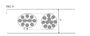
- FIG. 9 is a schematic diagram illustrating comparison between rubber topping gauges of a rolled sheet including the elliptical steel cord according to the present invention and of a rolled sheet including a circular steel cord according to a related art.
- the topping gauge is reduced as much as C (see FIG. 9 ).
- reference character G denotes a width of the carcass ply 10.
- the filament of the first-layer core has an elliptical or rectangular shape like in the present invention, a variation in a residual rotation value is reduced. This prevents an end portion of the steel cord from floating or sinking due to rolling attributable residual rotation, resulting improvement in processability.
- the diameter of the steel cord is reduced. Furthermore, the interval between the steel cords as well as the number of filaments in the rolled sheet can be reduced. This results in a reduction in the thickness of the rolled sheet, and the gauge of the rubber topping is minimized as compared with conventional materials. This also results in a reduction in the weight of a tire.
- rolling resistance performance is improved, increasing fuel efficiency.
- a wire rod having a diameter of 5.5 mm and containing 0.92% by weight of carbon was drawn, the wire rod was subjected to heat treatment and brass plating until the diameter of the wire rod became 0.75 mm. Through these processes, filaments were obtained.
- the second-layer core was formed by twisting 8 filaments each having a diameter of 0.35 mm around the surface of the first-layer core.
- a steel cord sample according to the present invention was prepared.
- Example sample physical properties including fatigue limit stress, initial rubber adhesion, heat aging, hot water resistance, rotation value, interval between cords, and rolling resistance performance were measured and are summarized in Table 1.
- the rotation value is set to 1 when the steel cord made one turn. About 72 samples were tested to obtain a variation. * Interval between cords: this is a value when a width of a rolled belt is 1800 mm and EPI is 19. * Rolling resistance performance was measured by applying samples to a tire of 12R22.5 which is a tire for a truck or a bus.
- the filament of the first-layer core is manufactured to have an elliptical or rectangular cross section as in Example, it is possible to reduce the diameter of the steel cord. Furthermore, even though the number of filaments constituting the first-layer core is reduced in comparison with Comparative Example 2, since the interval between cords is reduced, fatigue resistance of rubber is improved.
- the steel cord according to the present invention can prevent topping gauge reduction and eliminate the variation in rotation value. Furthermore, since the steel cord according to the present invention has a reduced weight, rolling resistance performance is also improved.
Abstract
Description
- The present disclosure relates to a tire-reinforcing steel cord for a vehicle, and more particularly to a tire-reinforcing steel cord having a double layer structure in which a first-layer core has an elliptical or rectangular cross section, and a radial tire using the same. The tire-reinforcing steel cord can improve processability, fatigue characteristics, and rolling resistance of a tire, leading to an increase in fuel efficiency of a vehicle.
- A steel cord is a construction of several steel wires and is obtained by plating carbon steel wires with brass, subjecting the brass-plated carbon steel wires to a drawing process, and twisting the drawn wires in the combination of 1×3, 1×4, 2+2, 2+7, 3+6, 3+9+15, or the like according to use of the manufactured steel wire. The steel cord is superior to any other reinforcing material in terms of strength, modulus, thermal resistance, fatigue resistance, etc., so that it is being used as material for reinforcing rubber articles such as tires, conveyer belts, etc.
- Generally a steel belt used for a tire is obtained by arranging 300 to 600 steel cords, in each of which multiple steel wires are twisted, side by side, and placing and rolling topping rubber layers on the top and bottom surfaces of the arranged steel cords. It is necessary for the steel cords to have strong adhesion to the rubber layers and have excellent durability in a harsh environment while a vehicle is running.
- In the rolling-processed structure which has undergone rolling, tensile strength occurs in a compressed direction due to an elastic recovery characteristic of the steel cord. When the rolling-processed structure is cut into pieces, bending deformation of the rubber layers and the steel cords is likely to occur, and thus there is difficulty in automatic connection work in a subsequent process. Accordingly, it is important to control the bending deformation. In order to improve workability in a subsequent tire manufacturing process, when the rolling-processed structure is cut into pieces each having a predetermined unit length, structural safety is required. That is, it is necessary to prevent ends of a piece of the rolling-processed structure having the unit length obtained through the cutting from floating or sinking. Adjustment of rolling of the steel cords is important in maintaining structural stability of rubber-topped rolling-processed steel cords.
- The rolling of the steel cord is referred to as residual rotation. When a torsion torque is applied to each steel wire filament to deform the steel wire such that the steel wire is twisted in a predetermined manner, the filament which is elastically deformed tends to be untwisted in a direction opposite to a twisting direction due to the elastic recovery characteristic, and a filament which has undergone excessive plastic deformation tends to be further twisted in the same direction as the twisting direction. Accordingly, after the steel cord is manufactured, residual rotation occurs.
- In the steel cord industry, an overtwister, prestress roller, etc. are used to stabilize residual rotation or prevent occurrence of residual rotation. However, since it is difficult to fundamentally prevent the rolling attributable to a torsion deformation force applied to filaments when manufacturing the steel cord by twisting multiple steel filaments in a direction, improvement in this aspect is required.
- Generally, a steel cord for a heavy duty tire is prepared by twisting multiple filaments of two layers or three layers. This steel cord has a dense structure in which there is no gap between the steel filaments. Rubber infiltration into the inside of the steel cord is poor. Therefore, if a tire is repeatedly bent by external force, damages of both mechanical wear and chemical corrosion, i.e., fretting fatigue occurs due to friction between the filaments and infiltration of moisture or salt, respectively. This deteriorates durability of a tire.
- According to an exemplary embodiment, a tire-reinforcing steel cord includes two or more core layers in which a first core layer of the two or more core layers has an elliptical or rectangular cross section instead of a circular cross section. This structure leads to a reduction in the number of steel cords used, resulting in a lightweight steel cord. This structure also improves manufacturing processes by reducing a variation in a rotation value of the cord and durability of the tire-reinforcing steel cord by minimizing topping gauge.
- In addition, the present invention is also intended to propose a radial tire having a low rolling resistance which can meet the demand for a lightweight tire for a truck or a bus. This radial tire can improve running stability and fuel efficiency of a vehicle.
- In an embodiment, a tire-reinforcing steel cord includes a double layer structure including a first core layer and a second core layer serving as an outer layer surrounding the first core layer, the first core layer made up of one or more filaments each having a substantially elliptical or rectangular cross section, the second core layer being made up of a plurality of twisted filaments each having a circular cross section.
- The first-layer core may include one filament or two filaments, and the second-layer core may include seven to nine filaments.
- A ratio of a short-axis size S to a long-axis size B (short-to-long axis ratio) of the filament of the first-layer core may be 0.3 to 0.9, and that of the filament of the second-layer core may be 0.9 or more, so that the filament of the second-layer core has a substantially circular cross section shape.
- The filaments in the first-layer core and the second-layer core may be prepared by drawing carbon steel containing 0.70% to 1.20% by weight of carbon and plating the surface of the drawn carbon steel with a metallic material in a thickness of 0.01 to 5.00 µm, in which the metallic material may be any one selected from the group consisting of brass, bronze, copper, zinc, an alloy of brass and nickel, and an alloy of brass and cobalt.
- According to another aspect of the present invention, there is provided a radial tire including the tire-reinforcing steel cording according to the former aspect which is applied to any one of a carcass, a chafer, and a belt.
- In the tire-reinforcing steel cord and the radial tire using the same according to the present invention, the first-layer core is manufactured to have an elliptical or rectangular cross section in order to increase a gap into which rubber can infiltrate and reduce a variation in a rotation value. This improves manufacturing processes and minimizes topping gauge.
- According to an exemplary embodiment of the present invention, since rubber infiltration is improved, corrosion resistance is increased, and deterioration of rubber adhesion is suppressed. Accordingly, a tire using the tire-reinforcing steel cord according to the present invention improves in durability, thus having longer lifespan.
- Since the tire-reinforcing steel cord according to an exemplary embodiment of the present invention has a relatively small diameter and includes a relatively smaller number of filaments compared with conventional tire-reinforcing steel cords, the tire-reinforcing steel cord according to the present invention leads to a lightweight tire and improvement in fuel efficiency.
- The above and other objects, features and other advantages of the present invention will be more clearly understood from the following detailed description when taken in conjunction with the accompanying drawings, in which:
-
FIG. 1 is a cross-sectional view illustrating a steel cord having a double layer structure of 3 x 8 according to a related art; -
FIG. 2 is a cross-sectional view illustrating a steel cord having a double layer structure of 2 x 7 according to a first embodiment of the present invention; -
FIG. 3 is a cross-sectional view illustrating a steel cord having a double layer structure of 2 x 7 according to a second embodiment of the present invention; -
FIG. 4 is a cross-sectional view illustrating a steel cord having a double layer structure of 2 x 7 according to a third embodiment of the present invention; -
FIG. 5 is an explanatory diagram describing the pitch of wave-shaped filaments used in the embodiments of the present invention; -
FIG. 6 is an explanatory diagram describing sizes of a long axis and a short axis of an elliptical or rectangular cross section of a filament serving as a first-layer core of the steel cord according to the first embodiment; -
FIG. 7 is a schematic cross-sectional diagram illustrating a heavy duty tire to which a tire-reinforcing steel cord according to the present invention is applied; -
FIG. 8 is a schematic cross-sectional diagram illustrating a half-finished carcass in which the tire-reinforcing steel cord according to the present invention is included; and -
FIG. 9 is a schematic view illustrating comparison between rubber topping gauges of a rolled sheet including an elliptical steel cord according to the present invention and of a rolled sheet including a circular steel cord according to a related art. - Exemplary embodiments will now be described in greater detail hereinafter with reference to the accompanying drawings, in which embodiments of the invention are shown. These exemplary embodiments may, however, be embodied in many different forms and should not be construed as limited to the embodiments set forth herein. Rather, these embodiments are provided so that this disclosure will be thorough and complete, and will fully convey the scope of the invention to those skilled in the art. Like reference numerals refer to like elements throughout.
- It will be understood that, although the terms first, second, third, etc. may be used herein to describe various elements, components, regions, layers and/or sections, these elements, components, regions, layers and/or sections should not be limited by these terms. These terms are only used to distinguish one element, component, region, layer or section from another element, component, region, layer or section. Thus, a first element, component, region, layer or section discussed below could be termed a second element, component, region, layer or section without departing from the teachings of the present invention.
- The terminology used herein is for the purpose of describing particular embodiments only and is not intended to be limiting of the invention. As used herein, the singular forms "a," "an" and "the" are intended to include the plural forms as well, unless the context clearly indicates otherwise. It will be further understood that the terms "comprises" and/or "comprising," when used in this specification, specify the presence of stated features, regions, integers, steps, operations, elements, and/or components, but do not preclude the presence or addition of one or more other features, regions, integers, steps, operations, elements, components, and/or groups thereof.
- Unless otherwise defined, all terms (including technical and scientific terms) used herein have the same meaning as commonly understood by one of ordinary skill in the art to which this invention belongs. It will be further understood that terms, such as those defined in commonly used dictionaries, should be interpreted as having a meaning that is consistent with their meaning in the context of the relevant art and the present disclosure, and will not be interpreted in an idealized or overly formal sense unless expressly so defined herein.
- A tire-reinforcing steel cord according to a first embodiment includes a first-layer core made up of one or more steel filaments, and a second-layer core made up of a plurality of steel filaments which are twisted and provided as an outer layer to surround the first-layer core. The steel filament of the first-layer core has a substantially elliptical or rectangular cross section, and the steel filaments of the second-layer core have a substantially circular cross section.
-
FIG. 2 is a cross-sectional view illustrating the tire-reinforcing steel cord according to the first embodiment. With reference toFIG. 2 , the tire-reinforcing steel cording according to the first embodiment includes a first-layer core 1 made up of one or two filaments 1a and a second-layer core 2 made up of 7 to 9filaments 2b. For example, the steel cord may have a structure of 1+7, 1+8, 1+9, 2+7, 2+8, or 2+9. - A plurality of
filaments 1a, 1b, and 1c which constitute the first-layer core 1 may be arranged in parallel with each other, or may be twisted. - The cross section of the filaments constituting the first-
layer core 1 is not a circular shape but is an elliptical shape (refer to 1a inFIG. 2 ) or a rectangular shape (refer to 1b inFIG. 3 ). Alternatively, it may be any shape in which a ratio of a short-axis size to a long-axis size is not 1, like a hexagonal shape. InFIG. 3 , reference characters D1 and D2 denote a long axis and a short axis of the steel cord, respectively. - The filaments constituting the first-
layer core 1 and the second-layer core 2 may be two-dimensionally waved filaments with a predetermined pitch.FIG. 5 is an enlarged view illustrating a two-dimensionally wavedfilament 1a or 2b used for the steel cord according to one embodiment of the present invention. With reference toFIG. 5 , in the steel cord according to one embodiment of the present invention, part or all of the filaments constituting the first-layer core and the second-layer core are two-dimensionally waved as illustrated inFIG. 5 . The two-dimensionally waved filaments meet the following conditions.

- Here, "d" is the diameter mm of the filament of the first-layer or second-layer core, L is the wavelength mm of two dimensional waves, and A is an amplitude mm of the two dimensional waves.
- The diameter d of the filaments constituting the first-
layer core 1 and the second-layer core 2 of the steel cord according to one embodiment of the present invention is in a range of 0.10 mm ≤ d ≤ 0.40 mm. If the diameter is less than 0.10 mm, the strength of the steel cord is insufficient, it is difficult to manufacture the filaments, and manufacturing costs of the steel cord increase. Conversely, if the diameter is greater than 0.40 mm, flexibility of the filaments is insufficient, deteriorating durability of a tire. -
FIG. 6 is an enlarged cross-sectional view illustrating the filament 1a constituting the first-layer core 1 of the steel cord according to one embodiment of the present invention. The filament 1a has an elliptical or rectangular cross section. A ratio of a short-axis size S to a long-axis size B of the filament 1a of the first-layer core 1 is 0.3 to 0.9. On the other hand, a ratio of a short-axis size S to a long-axis size B of thefilament 2b constituting the second-layer core 2 is 0.9 or higher. The diameter of thefilament 2b of the steel cord which has an elliptical or rectangular cross section is an average value of the long-axis size and the short-axis size of the cross section, i.e., a value obtained by adding the long-axis size and the short-axis size of the cross section and dividing the sum by 2. If the ratio of the short-axis size to the long axis size is lower than 0.3, there is an advantage that rubber infiltration into the steel cord improves but the thickness of the rubber-topped sheet increases because the diameter of the steel cord is excessively large. On the other hand, if the ratio of the short-axis size to the long-axis size is higher than 0.9, a gap between the first-layer core and the second-layer core decreases, resulting in deterioration of the rubber infiltration into the steel cord. - The
filaments 1a and 2b constituting the first-layer core 1 and the second-layer core 2 are obtained by drawing carbon steel containing 0.7% to 1.20% by weight of carbon, and plating the drawn carbon steel with a metallic material, such as brass, bronze, copper, zinc, an alloy of brass and nickel, or an alloy of brass and cobalt in a thickness of 0.01 to 5.00 µm. If the content of carbon in thefilaments 1a and 2b constituting the first-layer core 1 and the second-layer core 2 is less than 0.70% by weight, the tire-reinforcing steel cord has a strength which cannot meet the standard of reinforcing materials for a tire or becomes excessively heavy. On the other hand, if the content of carbon in thefilaments 1a and 2b is greater than 1.20% by weight, wiring breakage remarkably increases when drawing the steel into superfine filaments. That is, processability is deteriorated. When the surfaces of thefilaments 1a and 2b of the first-layer core 1 and the second-layer core 2 are plated, adhesion between thefilaments 1a and 2b and rubber greatly increases. Another aspect of the present invention is to provide a radial tire to which the tire-reinforcing steel cord described above is applied. - The tire-reinforcing steel cord according to the present invention may be applied to at least one of the components of a tire, including a carcass, a chafer, and a belt.
-
FIG. 7 is a schematic cross-sectional view illustrating a tire for a vehicle to which the tire-reinforcing steel cord according to the present invention is applied. A well-known tire for a bus or a truck includes a thread 1' which comes into direct contact with the road surface, a carcass 2' serving as a framework of a tire, a belt 3 formed by belt elements 3a, 3b, 3c and 3d, and disposed between the thread 1' and the carcass 2', an inner liner 4 which prevents air leakage, a side wall which protects the carcass 2' and performs flexing motion (i.e., bending and stretching), a shoulder 6 disposed between the thread 1' and the sidewall 5, and a bead 7 which surrounds an end portion of the carcass 2' and attaches a tire to a rim. - In the radial tire for a heavy duty tire having the above-described structure, stress concentrates on the bead 7 and the belt 3. Accordingly a steel chafer 8 is used to reinforce the bead 7 in order to improve durability of the tire. The steel cord is provided in the steel chafer 8 and the belt 8 as a reinforcement material.
- For example, as shown in
FIG. 8 , a half-finished carcass (carcass ply) 10 is obtained through the following method. First,carcass cords 13 are arranged at regular intervals, a rubber topping 11 is placed on thecarcass cords 13, and a stacked structure is subjected to rolling, producing a rolling-processed structure.FIG. 9 is a schematic diagram illustrating comparison between rubber topping gauges of a rolled sheet including the elliptical steel cord according to the present invention and of a rolled sheet including a circular steel cord according to a related art. When the elliptical filaments are used like in the present invention, the topping gauge is reduced as much as C (seeFIG. 9 ). For this reason, the weight of a tire is reduced accordingly, and thus cost saving can be achieved. As the ratio of the short-axis size A to the long-axis size C of the filament 1a of the first-layer core 1 is decreased, the value of the C increase. Further, as the C is increased, the weight of a tire decreases and the performance of rolling resistance RR improves. InFIG. 9 , reference character G denotes a width of thecarcass ply 10. - When the filament of the first-layer core has an elliptical or rectangular shape like in the present invention, a variation in a residual rotation value is reduced. This prevents an end portion of the steel cord from floating or sinking due to rolling attributable residual rotation, resulting improvement in processability.
- According to the present invention, the diameter of the steel cord is reduced. Furthermore, the interval between the steel cords as well as the number of filaments in the rolled sheet can be reduced. This results in a reduction in the thickness of the rolled sheet, and the gauge of the rubber topping is minimized as compared with conventional materials. This also results in a reduction in the weight of a tire. When the tire-reinforcing steel cord is applied to a tire of a vehicle, rolling resistance performance is improved, increasing fuel efficiency.
- The present invention will be described in greater detail using Examples and Comparative Examples. However, the present invention is not limited by the following description.
- In order to compare characteristics of a steel cord according to a related art and a steel cord according to the present invention, a wire rod having a diameter of 5.5 mm and containing 0.92% by weight of carbon was drawn, the wire rod was subjected to heat treatment and brass plating until the diameter of the wire rod became 0.75 mm. Through these processes, filaments were obtained. The first-layer core was prepared by twisting two filaments having an elliptical cross section (B/A = 0.6). The second-layer core was formed by twisting 8 filaments each having a diameter of 0.35 mm around the surface of the first-layer core. Thus, a steel cord sample according to the present invention was prepared.
- For the Example sample, physical properties including fatigue limit stress, initial rubber adhesion, heat aging, hot water resistance, rotation value, interval between cords, and rolling resistance performance were measured and are summarized in Table 1.
- For a conventional steel cord (refer to
FIG. 1 ) having a 3+9 double layer structure according to Comparative Example 1 in which the cross section of the filaments of the first-layer core and the second-layer core is circular, physical properties were measured in the same manner as in Example 1 and are summarized in Table 1. - For a conventional steel cord (refer to
FIG. 1 ) having a 3+8 double layer structure according to Comparative Example 2 in which the cross section of the filaments of the first-layer core and the second-layer core is circular, physical properties were measured in the same manner as in Example 1 and are summarized in Table 1.Table 1 Classification Comparative Example 1 Comparative Example 2 Example 1 Specification 3+9(0.20) 3+8(0.20) 2+8(0.20) Wire carbon content (wt %) 0.82 0.92 0.92 Cord diameter(mm) 1.08 0.85 0.75 Fatigue limit stress (kgf/mm2) over 90 over 90 over 90 Initial rubber adhesion (150-Cx30min) 106 105 114 Heat aging (100°C Oven) 7 days 95 106 111 14 days 85 98 101 21 days 70 85 92 Moisture tolerance (70 °C,96%RH) 7 days 94 104 110 14 days 69 100 102 21 days 62 85 95 Hot water resistance(70 °C) 7 days 84 100 107 14 days 66 89 98 21 days 53 84 92 Salt water resistance (NaCl, 20%) 7 days 85 103 108 14 days 65 91 97 21 days 51 82 91 Topping gauge(mm) 1.50 1.20 1.05 Variation in rotation value 0.6 0.6 0.1 Interval between cords(mm) 0.2 0.5 0.4 Rolling resistance(RR) 6.5 6.0 5.5 * Fatigue limit stress was measured by a Rotating Bean Tester (RBT) made by Bekaert (a sample is rotated one million or more times under a fatigue limit stress).
* Initial rubber adhesion was measured by ASTM D2229-99 manufactured by Instron under conditions of 150°C and 30 minutes.
* Heat aging was measured under a condition of 100°C oven and moisture tolerance was measured under conditions of 70°C, 96%RH, by determining a ratio of adhesion before and after treatment. The adhesion was measured by ASTM D2229-99 manufactured by Instron.
* Hot water resistance was measured at 70°C, and salt water resistance was measured at NaCl 20% by determining a ratio of adhesion before and after treatment. The adhesion was measured by ASTM D2229-99 manufactured by Instron.
* Rotation value: A steel cord is unspooled as long as 6 m from a spool and the number of rotations of the steel cord was measured. The rotation value is set to 1 when the steel cord made one turn. About 72 samples were tested to obtain a variation.
* Interval between cords: this is a value when a width of a rolled belt is 1800 mm and EPI is 19.
* Rolling resistance performance was measured by applying samples to a tire of 12R22.5 which is a tire for a truck or a bus. - As understood from Table 1, when the filament of the first-layer core is manufactured to have an elliptical or rectangular cross section as in Example, it is possible to reduce the diameter of the steel cord. Furthermore, even though the number of filaments constituting the first-layer core is reduced in comparison with Comparative Example 2, since the interval between cords is reduced, fatigue resistance of rubber is improved. The steel cord according to the present invention can prevent topping gauge reduction and eliminate the variation in rotation value. Furthermore, since the steel cord according to the present invention has a reduced weight, rolling resistance performance is also improved.
- Although a preferred embodiment of the present invention has been described for illustrative purposes, those skilled in the art will appreciate that various modifications, additions and substitutions are possible, without departing from the scope and spirit of the invention as disclosed in the accompanying claims. Accordingly, the present invention is defined only by a description of the appended claims and equivalents thereof may fall within the scope of the invention.
Claims (12)
- A tire-reinforcing steel cord comprising:a first-layer core including one or more filaments; anda second-layer core including a plurality of filaments which are twisted around the surface of the first-layer core, wherein the filament of the first-layer core has a substantially elliptical or rectangular cross section, and the filament of the second-layer core has a circular cross section.
- The tire-reinforcing steel cord according to claim 1, wherein the first-layer core includes 1 or 2 filament(s) and the second-layer core includes 7 to 9 filaments.
- The tire-reinforcing steel cord according to claim 2. wherein the steel core has a structure of 1+7, 1+8, 1+9, 2+7, 2+8, or 2+9.
- The tire-reinforcing steel cord according to claim 1, wherein the plurality of filaments constituting the first-layer core are arranged to be in parallel with each other, or twisted with each other.
- The tire-reinforcing steel cord according to claim 1, wherein a ratio of a short-axis size to a long-axis size of the filaments constituting the first-layer core is in a range of 0.3 to 0.9.
- The tire-reinforcing steel cord according to claim 1, wherein a ratio of a short-axis size to a long-axis size of the filaments constituting the second-layer core is higher than 0.9.
- The tire-reinforcing steel cord according to claim 1, wherein the filaments constituting the first-layer core and the second-layer core have a diameter d in a range of 0.10 to 0.40 mm, and a twisting period of the filaments is 20 to 50 times the diameter of the filaments.
- The tire-reinforcing steel cord according to claim 1, wherein the first-layer core and the second-layer core are the same or different in twisting directions of the filaments.
- The tire-reinforcing steel cord according to claim 1, wherein one or all of the filaments constituting the first-layer core and the second-layer core are two-dimensionally waved.
- The tire-reinforcing steel cord according to claim 7, wherein the diameter (d) of the filaments, a wavelength (L) of two-dimensional waves, and an amplitude (A) of the two-dimensional waves are set to values satisfying the following conditions:


- The tire-reinforcing steel cord according to claim 1, wherein the filaments constituting the first-layer core and the second-layer core are prepared by drawing carbon steel containing 0.70% to 1.20% by weight of carbon, plating a surface of the drawn steel with brass, bronze, copper, an alloy of brass and nickel, or an alloy of brass and cobalt in a thickness of 0.01 to 5.0 µm.
- A radial tire comprising the tire-reinforcing steel cord according to nay one of claims 1 to 11 applied to at least one component selected from a carcass, a chafer, and a belt.
Applications Claiming Priority (1)
| Application Number | Priority Date | Filing Date | Title |
|---|---|---|---|
| KR1020130107024A KR101523429B1 (en) | 2013-09-06 | 2013-09-06 | Steel cord for reinforcing a tire and radial tire using the same |
Publications (2)
| Publication Number | Publication Date |
|---|---|
| EP2845749A1 true EP2845749A1 (en) | 2015-03-11 |
| EP2845749B1 EP2845749B1 (en) | 2018-01-03 |
Family
ID=50473088
Family Applications (1)
| Application Number | Title | Priority Date | Filing Date |
|---|---|---|---|
| EP14163669.6A Active EP2845749B1 (en) | 2013-09-06 | 2014-04-07 | Tire-reinforcing steel cord and radial tire using the same |
Country Status (5)
| Country | Link |
|---|---|
| US (1) | US9610806B2 (en) |
| EP (1) | EP2845749B1 (en) |
| JP (1) | JP5883898B2 (en) |
| KR (1) | KR101523429B1 (en) |
| CN (1) | CN104420378B (en) |
Cited By (4)
| Publication number | Priority date | Publication date | Assignee | Title |
|---|---|---|---|---|
| EP3009560A3 (en) * | 2014-10-14 | 2016-06-29 | Hongduk Industrial Co., Ltd. | Steel cord for tire reinforcement |
| CN109562647A (en) * | 2016-08-05 | 2019-04-02 | 株式会社普利司通 | Tire all-steel cord and the pneumatic tire for having used the tire all-steel cord |
| EP3495165A4 (en) * | 2016-08-05 | 2019-06-12 | Bridgestone Corporation | Pneumatic tire |
| EP3495164A4 (en) * | 2016-08-05 | 2019-06-12 | Bridgestone Corporation | Pneumatic tire |
Families Citing this family (8)
| Publication number | Priority date | Publication date | Assignee | Title |
|---|---|---|---|---|
| WO2017144275A1 (en) * | 2016-02-23 | 2017-08-31 | Nv Bekaert Sa | Energy absorption assembly |
| WO2017156737A1 (en) * | 2016-03-17 | 2017-09-21 | Nv Bekaert Sa | A m+n steel cord for reinforcing rubber product |
| JP6520985B2 (en) * | 2017-05-02 | 2019-05-29 | 横浜ゴム株式会社 | Bead ring and method of manufacturing the same |
| CN107953728B (en) * | 2017-11-27 | 2020-02-11 | 江苏兴达钢帘线股份有限公司 | Cable type tire bead and tire |
| CN109338768B (en) * | 2018-12-03 | 2023-11-24 | 江苏兴达钢帘线股份有限公司 | High-permeability steel cord with 2+2+8×N structure |
| US20220307197A1 (en) * | 2020-08-26 | 2022-09-29 | Sumitomo Electric Tochigi Co., Ltd. | Steel cord and tire |
| CN113293633A (en) * | 2021-06-28 | 2021-08-24 | 嘉兴东方钢帘线有限公司 | Compact steel cord with 2+ N structure and manufacturing method thereof |
| JP2023094366A (en) * | 2021-12-23 | 2023-07-05 | 住友ゴム工業株式会社 | tire |
Citations (3)
| Publication number | Priority date | Publication date | Assignee | Title |
|---|---|---|---|---|
| EP0125518A2 (en) * | 1983-05-16 | 1984-11-21 | Akzo Patente GmbH | Cord for the reinforcement of elastomers |
| JP2001234486A (en) * | 2000-02-25 | 2001-08-31 | Tokyo Seiko Co Ltd | Steel cord and rubber composite material |
| WO2011029679A1 (en) * | 2009-09-11 | 2011-03-17 | Nv Bekaert Sa | Oval steel cord with oval wires |
Family Cites Families (17)
| Publication number | Priority date | Publication date | Assignee | Title |
|---|---|---|---|---|
| JP2642989B2 (en) * | 1989-05-26 | 1997-08-20 | 住友ゴム工業株式会社 | Steel plies for tires |
| JP3111379B2 (en) * | 1996-07-15 | 2000-11-20 | 東京製綱株式会社 | Steel cords for rubber reinforcement and radial tires |
| KR100493671B1 (en) * | 1998-09-10 | 2005-08-31 | 한국타이어 주식회사 | Steel Cords for Radial Tires |
| KR100493673B1 (en) * | 1999-01-08 | 2005-06-03 | 한국타이어 주식회사 | A radial tire applied a steel cord in the carcass |
| KR100296075B1 (en) * | 1999-03-05 | 2001-07-03 | 조충환 | A rubber and a steel cord for reinforcement of a tire with increased rubber penetration |
| JP3276612B2 (en) * | 1999-03-19 | 2002-04-22 | 東京製綱株式会社 | Steel cord and radial tire |
| FR2795751A1 (en) * | 1999-06-29 | 2001-01-05 | Michelin Soc Tech | MULTILAYER STEEL CABLE FOR PNEUMATIC CARCASS |
| KR100305503B1 (en) * | 1999-06-29 | 2001-09-24 | 조충환 | A steel cord for tire and a radial tire using the same |
| EP1349984A1 (en) * | 2001-01-04 | 2003-10-08 | Société de Technologie Michelin | Multi-layered steel cord for a tyre crown reinforcement |
| KR100443564B1 (en) * | 2001-11-16 | 2004-08-09 | 홍덕스틸코드주식회사 | Steel cord for reinforcing with a good rubber penetration properties and method for making the same |
| JP2004058707A (en) * | 2002-07-24 | 2004-02-26 | Toyo Tire & Rubber Co Ltd | Pneumatic radial tire |
| KR100635596B1 (en) * | 2004-03-31 | 2006-10-18 | 금호타이어 주식회사 | Steel cord for tire reinforcement |
| KR100591681B1 (en) * | 2004-09-30 | 2006-06-20 | 금호타이어 주식회사 | Hybrid Steel Cord For Reinforcing Carcass of Tire Inside Using Rayon and Carbon Steel |
| JP2007314010A (en) * | 2006-05-25 | 2007-12-06 | Toyo Tire & Rubber Co Ltd | Pneumatic radial tire |
| EP2382101A1 (en) * | 2009-01-28 | 2011-11-02 | NV Bekaert SA | Crimped flat wire as core of oval cord |
| KR101106367B1 (en) * | 2009-12-22 | 2012-01-18 | 한국타이어 주식회사 | Steel Cord for Reinforcement of a Tire with Increased Rubber Penetration and Air Injection Radial Tire Comprising The Same |
| JP5602609B2 (en) * | 2010-12-16 | 2014-10-08 | 株式会社ブリヂストン | Steel cord for reinforcing rubber articles and pneumatic tire using the same |
-
2013
- 2013-09-06 KR KR1020130107024A patent/KR101523429B1/en active IP Right Grant
-
2014
- 2014-04-07 EP EP14163669.6A patent/EP2845749B1/en active Active
- 2014-04-09 JP JP2014080505A patent/JP5883898B2/en active Active
- 2014-04-09 US US14/248,829 patent/US9610806B2/en active Active
- 2014-04-30 CN CN201410180957.9A patent/CN104420378B/en active Active
Patent Citations (3)
| Publication number | Priority date | Publication date | Assignee | Title |
|---|---|---|---|---|
| EP0125518A2 (en) * | 1983-05-16 | 1984-11-21 | Akzo Patente GmbH | Cord for the reinforcement of elastomers |
| JP2001234486A (en) * | 2000-02-25 | 2001-08-31 | Tokyo Seiko Co Ltd | Steel cord and rubber composite material |
| WO2011029679A1 (en) * | 2009-09-11 | 2011-03-17 | Nv Bekaert Sa | Oval steel cord with oval wires |
Cited By (5)
| Publication number | Priority date | Publication date | Assignee | Title |
|---|---|---|---|---|
| EP3009560A3 (en) * | 2014-10-14 | 2016-06-29 | Hongduk Industrial Co., Ltd. | Steel cord for tire reinforcement |
| CN109562647A (en) * | 2016-08-05 | 2019-04-02 | 株式会社普利司通 | Tire all-steel cord and the pneumatic tire for having used the tire all-steel cord |
| EP3495163A4 (en) * | 2016-08-05 | 2019-06-12 | Bridgestone Corporation | Tire steel cord and pneumatic tire using same |
| EP3495165A4 (en) * | 2016-08-05 | 2019-06-12 | Bridgestone Corporation | Pneumatic tire |
| EP3495164A4 (en) * | 2016-08-05 | 2019-06-12 | Bridgestone Corporation | Pneumatic tire |
Also Published As
| Publication number | Publication date |
|---|---|
| CN104420378A (en) | 2015-03-18 |
| KR20150028459A (en) | 2015-03-16 |
| KR101523429B1 (en) | 2015-05-27 |
| CN104420378B (en) | 2017-12-05 |
| JP2015052192A (en) | 2015-03-19 |
| US9610806B2 (en) | 2017-04-04 |
| JP5883898B2 (en) | 2016-03-15 |
| EP2845749B1 (en) | 2018-01-03 |
| US20150068655A1 (en) | 2015-03-12 |
Similar Documents
| Publication | Publication Date | Title |
|---|---|---|
| EP2845749B1 (en) | Tire-reinforcing steel cord and radial tire using the same | |
| EP3027805B1 (en) | High elongation steel cord and pneumatic tire comprising said cord | |
| JP2936112B2 (en) | Steel cord for reinforcement | |
| CN102066653B (en) | Steel cord for reinforcing rubber article and adopt the pneumatic tire of this all-steel cord | |
| EP0373595A1 (en) | Steel cord fo reinforcing rubber | |
| US8720175B2 (en) | Crimped flat wire as core of oval cord | |
| KR20130069649A (en) | High-permeability elastic multistrand metal cable | |
| JP4633517B2 (en) | Steel cord and tire | |
| EP3279010A1 (en) | Cord-rubber composite and pneumatic tire | |
| JP2006283198A (en) | Steel cord and tire | |
| JP6717701B2 (en) | Steel cord for tire and pneumatic tire using the same | |
| US20220001696A1 (en) | Steel wire and tire | |
| JP2564507Y2 (en) | Steel cord for reinforcing rubber products | |
| KR100785241B1 (en) | Steel cord for radial tire | |
| JP2001000033U (en) | High tension cord | |
| JP2007031890A (en) | Steel cord and pneumatic radial tire | |
| JP3111379B2 (en) | Steel cords for rubber reinforcement and radial tires | |
| EP3222368B1 (en) | Carbon steel wire and method for manufacturing same | |
| JP2006283197A (en) | Steel cord and tire | |
| KR101222403B1 (en) | 2+5 type steel cord for tire of vehicle. | |
| EP4343055A1 (en) | Steel cord for reinforcing tire belt plies | |
| JP2009084727A (en) | Rubber-steel cord composite material, production method thereof, and pneumatic tire produced by using the same | |
| KR101018200B1 (en) | Heavy duty radial pneumatic tire with improved belt structure | |
| KR101522467B1 (en) | Steel cord for pneumatic radial tyre and pneumatic radial tyre thereof | |
| JP4248007B2 (en) | Steel cord for tire reinforcement |
Legal Events
| Date | Code | Title | Description |
|---|---|---|---|
| 17P | Request for examination filed |
Effective date: 20140407 |
|
| AK | Designated contracting states |
Kind code of ref document: A1 Designated state(s): AL AT BE BG CH CY CZ DE DK EE ES FI FR GB GR HR HU IE IS IT LI LT LU LV MC MK MT NL NO PL PT RO RS SE SI SK SM TR |
|
| AX | Request for extension of the european patent |
Extension state: BA ME |
|
| PUAI | Public reference made under article 153(3) epc to a published international application that has entered the european phase |
Free format text: ORIGINAL CODE: 0009012 |
|
| R17P | Request for examination filed (corrected) |
Effective date: 20150911 |
|
| RBV | Designated contracting states (corrected) |
Designated state(s): AL AT BE BG CH CY CZ DE DK EE ES FI FR GB GR HR HU IE IS IT LI LT LU LV MC MK MT NL NO PL PT RO RS SE SI SK SM TR |
|
| 17Q | First examination report despatched |
Effective date: 20161125 |
|
| GRAP | Despatch of communication of intention to grant a patent |
Free format text: ORIGINAL CODE: EPIDOSNIGR1 |
|
| RIC1 | Information provided on ipc code assigned before grant |
Ipc: B60C 15/06 20060101ALI20170707BHEP Ipc: D02G 3/12 20060101ALI20170707BHEP Ipc: D07B 1/06 20060101ALI20170707BHEP Ipc: B60C 9/04 20060101ALI20170707BHEP Ipc: D02G 3/48 20060101ALI20170707BHEP Ipc: B60C 9/20 20060101ALI20170707BHEP Ipc: B60C 9/00 20060101AFI20170707BHEP |
|
| INTG | Intention to grant announced |
Effective date: 20170804 |
|
| GRAS | Grant fee paid |
Free format text: ORIGINAL CODE: EPIDOSNIGR3 |
|
| GRAA | (expected) grant |
Free format text: ORIGINAL CODE: 0009210 |
|
| AK | Designated contracting states |
Kind code of ref document: B1 Designated state(s): AL AT BE BG CH CY CZ DE DK EE ES FI FR GB GR HR HU IE IS IT LI LT LU LV MC MK MT NL NO PL PT RO RS SE SI SK SM TR |
|
| REG | Reference to a national code |
Ref country code: GB Ref legal event code: FG4D |
|
| REG | Reference to a national code |
Ref country code: CH Ref legal event code: EP Ref country code: AT Ref legal event code: REF Ref document number: 959860 Country of ref document: AT Kind code of ref document: T Effective date: 20180115 |
|
| REG | Reference to a national code |
Ref country code: IE Ref legal event code: FG4D |
|
| REG | Reference to a national code |
Ref country code: DE Ref legal event code: R096 Ref document number: 602014019275 Country of ref document: DE |
|
| REG | Reference to a national code |
Ref country code: FR Ref legal event code: PLFP Year of fee payment: 5 |
|
| REG | Reference to a national code |
Ref country code: NL Ref legal event code: MP Effective date: 20180103 |
|
| REG | Reference to a national code |
Ref country code: LT Ref legal event code: MG4D |
|
| REG | Reference to a national code |
Ref country code: AT Ref legal event code: MK05 Ref document number: 959860 Country of ref document: AT Kind code of ref document: T Effective date: 20180103 |
|
| PG25 | Lapsed in a contracting state [announced via postgrant information from national office to epo] |
Ref country code: NL Free format text: LAPSE BECAUSE OF FAILURE TO SUBMIT A TRANSLATION OF THE DESCRIPTION OR TO PAY THE FEE WITHIN THE PRESCRIBED TIME-LIMIT Effective date: 20180103 |
|
| PG25 | Lapsed in a contracting state [announced via postgrant information from national office to epo] |
Ref country code: FI Free format text: LAPSE BECAUSE OF FAILURE TO SUBMIT A TRANSLATION OF THE DESCRIPTION OR TO PAY THE FEE WITHIN THE PRESCRIBED TIME-LIMIT Effective date: 20180103 Ref country code: NO Free format text: LAPSE BECAUSE OF FAILURE TO SUBMIT A TRANSLATION OF THE DESCRIPTION OR TO PAY THE FEE WITHIN THE PRESCRIBED TIME-LIMIT Effective date: 20180403 Ref country code: CY Free format text: LAPSE BECAUSE OF FAILURE TO SUBMIT A TRANSLATION OF THE DESCRIPTION OR TO PAY THE FEE WITHIN THE PRESCRIBED TIME-LIMIT Effective date: 20180103 Ref country code: HR Free format text: LAPSE BECAUSE OF FAILURE TO SUBMIT A TRANSLATION OF THE DESCRIPTION OR TO PAY THE FEE WITHIN THE PRESCRIBED TIME-LIMIT Effective date: 20180103 Ref country code: ES Free format text: LAPSE BECAUSE OF FAILURE TO SUBMIT A TRANSLATION OF THE DESCRIPTION OR TO PAY THE FEE WITHIN THE PRESCRIBED TIME-LIMIT Effective date: 20180103 Ref country code: LT Free format text: LAPSE BECAUSE OF FAILURE TO SUBMIT A TRANSLATION OF THE DESCRIPTION OR TO PAY THE FEE WITHIN THE PRESCRIBED TIME-LIMIT Effective date: 20180103 |
|
| PG25 | Lapsed in a contracting state [announced via postgrant information from national office to epo] |
Ref country code: SE Free format text: LAPSE BECAUSE OF FAILURE TO SUBMIT A TRANSLATION OF THE DESCRIPTION OR TO PAY THE FEE WITHIN THE PRESCRIBED TIME-LIMIT Effective date: 20180103 Ref country code: IS Free format text: LAPSE BECAUSE OF FAILURE TO SUBMIT A TRANSLATION OF THE DESCRIPTION OR TO PAY THE FEE WITHIN THE PRESCRIBED TIME-LIMIT Effective date: 20180503 Ref country code: LV Free format text: LAPSE BECAUSE OF FAILURE TO SUBMIT A TRANSLATION OF THE DESCRIPTION OR TO PAY THE FEE WITHIN THE PRESCRIBED TIME-LIMIT Effective date: 20180103 Ref country code: AT Free format text: LAPSE BECAUSE OF FAILURE TO SUBMIT A TRANSLATION OF THE DESCRIPTION OR TO PAY THE FEE WITHIN THE PRESCRIBED TIME-LIMIT Effective date: 20180103 Ref country code: RS Free format text: LAPSE BECAUSE OF FAILURE TO SUBMIT A TRANSLATION OF THE DESCRIPTION OR TO PAY THE FEE WITHIN THE PRESCRIBED TIME-LIMIT Effective date: 20180103 Ref country code: BG Free format text: LAPSE BECAUSE OF FAILURE TO SUBMIT A TRANSLATION OF THE DESCRIPTION OR TO PAY THE FEE WITHIN THE PRESCRIBED TIME-LIMIT Effective date: 20180403 Ref country code: PL Free format text: LAPSE BECAUSE OF FAILURE TO SUBMIT A TRANSLATION OF THE DESCRIPTION OR TO PAY THE FEE WITHIN THE PRESCRIBED TIME-LIMIT Effective date: 20180103 Ref country code: GR Free format text: LAPSE BECAUSE OF FAILURE TO SUBMIT A TRANSLATION OF THE DESCRIPTION OR TO PAY THE FEE WITHIN THE PRESCRIBED TIME-LIMIT Effective date: 20180404 |
|
| REG | Reference to a national code |
Ref country code: DE Ref legal event code: R097 Ref document number: 602014019275 Country of ref document: DE |
|
| PG25 | Lapsed in a contracting state [announced via postgrant information from national office to epo] |
Ref country code: IT Free format text: LAPSE BECAUSE OF FAILURE TO SUBMIT A TRANSLATION OF THE DESCRIPTION OR TO PAY THE FEE WITHIN THE PRESCRIBED TIME-LIMIT Effective date: 20180103 Ref country code: RO Free format text: LAPSE BECAUSE OF FAILURE TO SUBMIT A TRANSLATION OF THE DESCRIPTION OR TO PAY THE FEE WITHIN THE PRESCRIBED TIME-LIMIT Effective date: 20180103 Ref country code: EE Free format text: LAPSE BECAUSE OF FAILURE TO SUBMIT A TRANSLATION OF THE DESCRIPTION OR TO PAY THE FEE WITHIN THE PRESCRIBED TIME-LIMIT Effective date: 20180103 Ref country code: AL Free format text: LAPSE BECAUSE OF FAILURE TO SUBMIT A TRANSLATION OF THE DESCRIPTION OR TO PAY THE FEE WITHIN THE PRESCRIBED TIME-LIMIT Effective date: 20180103 |
|
| PLBE | No opposition filed within time limit |
Free format text: ORIGINAL CODE: 0009261 |
|
| STAA | Information on the status of an ep patent application or granted ep patent |
Free format text: STATUS: NO OPPOSITION FILED WITHIN TIME LIMIT |
|
| PG25 | Lapsed in a contracting state [announced via postgrant information from national office to epo] |
Ref country code: SM Free format text: LAPSE BECAUSE OF FAILURE TO SUBMIT A TRANSLATION OF THE DESCRIPTION OR TO PAY THE FEE WITHIN THE PRESCRIBED TIME-LIMIT Effective date: 20180103 Ref country code: DK Free format text: LAPSE BECAUSE OF FAILURE TO SUBMIT A TRANSLATION OF THE DESCRIPTION OR TO PAY THE FEE WITHIN THE PRESCRIBED TIME-LIMIT Effective date: 20180103 Ref country code: SK Free format text: LAPSE BECAUSE OF FAILURE TO SUBMIT A TRANSLATION OF THE DESCRIPTION OR TO PAY THE FEE WITHIN THE PRESCRIBED TIME-LIMIT Effective date: 20180103 Ref country code: MC Free format text: LAPSE BECAUSE OF FAILURE TO SUBMIT A TRANSLATION OF THE DESCRIPTION OR TO PAY THE FEE WITHIN THE PRESCRIBED TIME-LIMIT Effective date: 20180103 Ref country code: CZ Free format text: LAPSE BECAUSE OF FAILURE TO SUBMIT A TRANSLATION OF THE DESCRIPTION OR TO PAY THE FEE WITHIN THE PRESCRIBED TIME-LIMIT Effective date: 20180103 |
|
| REG | Reference to a national code |
Ref country code: CH Ref legal event code: PL |
|
| 26N | No opposition filed |
Effective date: 20181005 |
|
| REG | Reference to a national code |
Ref country code: BE Ref legal event code: MM Effective date: 20180430 |
|
| GBPC | Gb: european patent ceased through non-payment of renewal fee |
Effective date: 20180407 |
|
| REG | Reference to a national code |
Ref country code: IE Ref legal event code: MM4A |
|
| PG25 | Lapsed in a contracting state [announced via postgrant information from national office to epo] |
Ref country code: LU Free format text: LAPSE BECAUSE OF NON-PAYMENT OF DUE FEES Effective date: 20180407 |
|
| PG25 | Lapsed in a contracting state [announced via postgrant information from national office to epo] |
Ref country code: BE Free format text: LAPSE BECAUSE OF NON-PAYMENT OF DUE FEES Effective date: 20180430 Ref country code: SI Free format text: LAPSE BECAUSE OF FAILURE TO SUBMIT A TRANSLATION OF THE DESCRIPTION OR TO PAY THE FEE WITHIN THE PRESCRIBED TIME-LIMIT Effective date: 20180103 Ref country code: GB Free format text: LAPSE BECAUSE OF NON-PAYMENT OF DUE FEES Effective date: 20180407 Ref country code: CH Free format text: LAPSE BECAUSE OF NON-PAYMENT OF DUE FEES Effective date: 20180430 Ref country code: LI Free format text: LAPSE BECAUSE OF NON-PAYMENT OF DUE FEES Effective date: 20180430 |
|
| PG25 | Lapsed in a contracting state [announced via postgrant information from national office to epo] |
Ref country code: IE Free format text: LAPSE BECAUSE OF NON-PAYMENT OF DUE FEES Effective date: 20180407 |
|
| PG25 | Lapsed in a contracting state [announced via postgrant information from national office to epo] |
Ref country code: MT Free format text: LAPSE BECAUSE OF NON-PAYMENT OF DUE FEES Effective date: 20180407 |
|
| PG25 | Lapsed in a contracting state [announced via postgrant information from national office to epo] |
Ref country code: TR Free format text: LAPSE BECAUSE OF FAILURE TO SUBMIT A TRANSLATION OF THE DESCRIPTION OR TO PAY THE FEE WITHIN THE PRESCRIBED TIME-LIMIT Effective date: 20180103 |
|
| PG25 | Lapsed in a contracting state [announced via postgrant information from national office to epo] |
Ref country code: HU Free format text: LAPSE BECAUSE OF FAILURE TO SUBMIT A TRANSLATION OF THE DESCRIPTION OR TO PAY THE FEE WITHIN THE PRESCRIBED TIME-LIMIT; INVALID AB INITIO Effective date: 20140407 Ref country code: PT Free format text: LAPSE BECAUSE OF FAILURE TO SUBMIT A TRANSLATION OF THE DESCRIPTION OR TO PAY THE FEE WITHIN THE PRESCRIBED TIME-LIMIT Effective date: 20180103 |
|
| PG25 | Lapsed in a contracting state [announced via postgrant information from national office to epo] |
Ref country code: MK Free format text: LAPSE BECAUSE OF NON-PAYMENT OF DUE FEES Effective date: 20180103 |
|
| PGFP | Annual fee paid to national office [announced via postgrant information from national office to epo] |
Ref country code: FR Payment date: 20230306 Year of fee payment: 10 |
|
| PGFP | Annual fee paid to national office [announced via postgrant information from national office to epo] |
Ref country code: DE Payment date: 20230306 Year of fee payment: 10 |
|
| P01 | Opt-out of the competence of the unified patent court (upc) registered |
Effective date: 20230926 |