EP2845713B1 - Extruder mit einer Schnecke mit einem automatisch erfassbaren Sensor zur Bereitstellung charakteristischer Informationen für die Antriebseinheit - Google Patents
Extruder mit einer Schnecke mit einem automatisch erfassbaren Sensor zur Bereitstellung charakteristischer Informationen für die Antriebseinheit Download PDFInfo
- Publication number
- EP2845713B1 EP2845713B1 EP14176896.0A EP14176896A EP2845713B1 EP 2845713 B1 EP2845713 B1 EP 2845713B1 EP 14176896 A EP14176896 A EP 14176896A EP 2845713 B1 EP2845713 B1 EP 2845713B1
- Authority
- EP
- European Patent Office
- Prior art keywords
- extruder
- screw
- information
- control device
- clutch
- Prior art date
- Legal status (The legal status is an assumption and is not a legal conclusion. Google has not performed a legal analysis and makes no representation as to the accuracy of the status listed.)
- Active
Links
Images


Classifications
-
- B—PERFORMING OPERATIONS; TRANSPORTING
- B29—WORKING OF PLASTICS; WORKING OF SUBSTANCES IN A PLASTIC STATE IN GENERAL
- B29C—SHAPING OR JOINING OF PLASTICS; SHAPING OF MATERIAL IN A PLASTIC STATE, NOT OTHERWISE PROVIDED FOR; AFTER-TREATMENT OF THE SHAPED PRODUCTS, e.g. REPAIRING
- B29C48/00—Extrusion moulding, i.e. expressing the moulding material through a die or nozzle which imparts the desired form; Apparatus therefor
- B29C48/25—Component parts, details or accessories; Auxiliary operations
- B29C48/36—Means for plasticising or homogenising the moulding material or forcing it through the nozzle or die
- B29C48/50—Details of extruders
- B29C48/505—Screws
-
- B—PERFORMING OPERATIONS; TRANSPORTING
- B29—WORKING OF PLASTICS; WORKING OF SUBSTANCES IN A PLASTIC STATE IN GENERAL
- B29B—PREPARATION OR PRETREATMENT OF THE MATERIAL TO BE SHAPED; MAKING GRANULES OR PREFORMS; RECOVERY OF PLASTICS OR OTHER CONSTITUENTS OF WASTE MATERIAL CONTAINING PLASTICS
- B29B7/00—Mixing; Kneading
- B29B7/30—Mixing; Kneading continuous, with mechanical mixing or kneading devices
- B29B7/58—Component parts, details or accessories; Auxiliary operations
- B29B7/72—Measuring, controlling or regulating
- B29B7/728—Measuring data of the driving system, e.g. torque, speed, power, vibration
-
- B—PERFORMING OPERATIONS; TRANSPORTING
- B29—WORKING OF PLASTICS; WORKING OF SUBSTANCES IN A PLASTIC STATE IN GENERAL
- B29C—SHAPING OR JOINING OF PLASTICS; SHAPING OF MATERIAL IN A PLASTIC STATE, NOT OTHERWISE PROVIDED FOR; AFTER-TREATMENT OF THE SHAPED PRODUCTS, e.g. REPAIRING
- B29C48/00—Extrusion moulding, i.e. expressing the moulding material through a die or nozzle which imparts the desired form; Apparatus therefor
- B29C48/25—Component parts, details or accessories; Auxiliary operations
- B29C48/256—Exchangeable extruder parts
- B29C48/2564—Screw parts
-
- B—PERFORMING OPERATIONS; TRANSPORTING
- B29—WORKING OF PLASTICS; WORKING OF SUBSTANCES IN A PLASTIC STATE IN GENERAL
- B29C—SHAPING OR JOINING OF PLASTICS; SHAPING OF MATERIAL IN A PLASTIC STATE, NOT OTHERWISE PROVIDED FOR; AFTER-TREATMENT OF THE SHAPED PRODUCTS, e.g. REPAIRING
- B29C48/00—Extrusion moulding, i.e. expressing the moulding material through a die or nozzle which imparts the desired form; Apparatus therefor
- B29C48/25—Component parts, details or accessories; Auxiliary operations
- B29C48/92—Measuring, controlling or regulating
-
- B—PERFORMING OPERATIONS; TRANSPORTING
- B29—WORKING OF PLASTICS; WORKING OF SUBSTANCES IN A PLASTIC STATE IN GENERAL
- B29C—SHAPING OR JOINING OF PLASTICS; SHAPING OF MATERIAL IN A PLASTIC STATE, NOT OTHERWISE PROVIDED FOR; AFTER-TREATMENT OF THE SHAPED PRODUCTS, e.g. REPAIRING
- B29C2948/00—Indexing scheme relating to extrusion moulding
- B29C2948/92—Measuring, controlling or regulating
- B29C2948/92009—Measured parameter
- B29C2948/92114—Dimensions
- B29C2948/92123—Diameter or circumference
-
- B—PERFORMING OPERATIONS; TRANSPORTING
- B29—WORKING OF PLASTICS; WORKING OF SUBSTANCES IN A PLASTIC STATE IN GENERAL
- B29C—SHAPING OR JOINING OF PLASTICS; SHAPING OF MATERIAL IN A PLASTIC STATE, NOT OTHERWISE PROVIDED FOR; AFTER-TREATMENT OF THE SHAPED PRODUCTS, e.g. REPAIRING
- B29C2948/00—Indexing scheme relating to extrusion moulding
- B29C2948/92—Measuring, controlling or regulating
- B29C2948/92009—Measured parameter
- B29C2948/92114—Dimensions
- B29C2948/92142—Length
-
- B—PERFORMING OPERATIONS; TRANSPORTING
- B29—WORKING OF PLASTICS; WORKING OF SUBSTANCES IN A PLASTIC STATE IN GENERAL
- B29C—SHAPING OR JOINING OF PLASTICS; SHAPING OF MATERIAL IN A PLASTIC STATE, NOT OTHERWISE PROVIDED FOR; AFTER-TREATMENT OF THE SHAPED PRODUCTS, e.g. REPAIRING
- B29C2948/00—Indexing scheme relating to extrusion moulding
- B29C2948/92—Measuring, controlling or regulating
- B29C2948/92009—Measured parameter
- B29C2948/92304—Presence or absence; Sequence; Counting
-
- B—PERFORMING OPERATIONS; TRANSPORTING
- B29—WORKING OF PLASTICS; WORKING OF SUBSTANCES IN A PLASTIC STATE IN GENERAL
- B29C—SHAPING OR JOINING OF PLASTICS; SHAPING OF MATERIAL IN A PLASTIC STATE, NOT OTHERWISE PROVIDED FOR; AFTER-TREATMENT OF THE SHAPED PRODUCTS, e.g. REPAIRING
- B29C2948/00—Indexing scheme relating to extrusion moulding
- B29C2948/92—Measuring, controlling or regulating
- B29C2948/92009—Measured parameter
- B29C2948/92314—Particular value claimed
-
- B—PERFORMING OPERATIONS; TRANSPORTING
- B29—WORKING OF PLASTICS; WORKING OF SUBSTANCES IN A PLASTIC STATE IN GENERAL
- B29C—SHAPING OR JOINING OF PLASTICS; SHAPING OF MATERIAL IN A PLASTIC STATE, NOT OTHERWISE PROVIDED FOR; AFTER-TREATMENT OF THE SHAPED PRODUCTS, e.g. REPAIRING
- B29C2948/00—Indexing scheme relating to extrusion moulding
- B29C2948/92—Measuring, controlling or regulating
- B29C2948/92323—Location or phase of measurement
- B29C2948/92457—Drive section, e.g. gearbox, motor or drive fluids
-
- B—PERFORMING OPERATIONS; TRANSPORTING
- B29—WORKING OF PLASTICS; WORKING OF SUBSTANCES IN A PLASTIC STATE IN GENERAL
- B29C—SHAPING OR JOINING OF PLASTICS; SHAPING OF MATERIAL IN A PLASTIC STATE, NOT OTHERWISE PROVIDED FOR; AFTER-TREATMENT OF THE SHAPED PRODUCTS, e.g. REPAIRING
- B29C2948/00—Indexing scheme relating to extrusion moulding
- B29C2948/92—Measuring, controlling or regulating
- B29C2948/92504—Controlled parameter
- B29C2948/92514—Pressure
-
- B—PERFORMING OPERATIONS; TRANSPORTING
- B29—WORKING OF PLASTICS; WORKING OF SUBSTANCES IN A PLASTIC STATE IN GENERAL
- B29C—SHAPING OR JOINING OF PLASTICS; SHAPING OF MATERIAL IN A PLASTIC STATE, NOT OTHERWISE PROVIDED FOR; AFTER-TREATMENT OF THE SHAPED PRODUCTS, e.g. REPAIRING
- B29C2948/00—Indexing scheme relating to extrusion moulding
- B29C2948/92—Measuring, controlling or regulating
- B29C2948/92504—Controlled parameter
- B29C2948/92533—Torque
-
- B—PERFORMING OPERATIONS; TRANSPORTING
- B29—WORKING OF PLASTICS; WORKING OF SUBSTANCES IN A PLASTIC STATE IN GENERAL
- B29C—SHAPING OR JOINING OF PLASTICS; SHAPING OF MATERIAL IN A PLASTIC STATE, NOT OTHERWISE PROVIDED FOR; AFTER-TREATMENT OF THE SHAPED PRODUCTS, e.g. REPAIRING
- B29C2948/00—Indexing scheme relating to extrusion moulding
- B29C2948/92—Measuring, controlling or regulating
- B29C2948/92504—Controlled parameter
- B29C2948/9258—Velocity
- B29C2948/9259—Angular velocity
-
- B—PERFORMING OPERATIONS; TRANSPORTING
- B29—WORKING OF PLASTICS; WORKING OF SUBSTANCES IN A PLASTIC STATE IN GENERAL
- B29C—SHAPING OR JOINING OF PLASTICS; SHAPING OF MATERIAL IN A PLASTIC STATE, NOT OTHERWISE PROVIDED FOR; AFTER-TREATMENT OF THE SHAPED PRODUCTS, e.g. REPAIRING
- B29C2948/00—Indexing scheme relating to extrusion moulding
- B29C2948/92—Measuring, controlling or regulating
- B29C2948/92819—Location or phase of control
- B29C2948/92952—Drive section, e.g. gearbox, motor or drive fluids
-
- B—PERFORMING OPERATIONS; TRANSPORTING
- B29—WORKING OF PLASTICS; WORKING OF SUBSTANCES IN A PLASTIC STATE IN GENERAL
- B29C—SHAPING OR JOINING OF PLASTICS; SHAPING OF MATERIAL IN A PLASTIC STATE, NOT OTHERWISE PROVIDED FOR; AFTER-TREATMENT OF THE SHAPED PRODUCTS, e.g. REPAIRING
- B29C48/00—Extrusion moulding, i.e. expressing the moulding material through a die or nozzle which imparts the desired form; Apparatus therefor
- B29C48/25—Component parts, details or accessories; Auxiliary operations
- B29C48/96—Safety devices
Definitions
- the invention relates to an extruder according to claim 1.
- extruders are known to serve the treatment of masses which are processed in the working part respectively the cylinder via the one or more extruder screws rotating there.
- plastic materials may be mentioned which are melted and compounded in the extruder in order to be subsequently processed further, for example for the formation of plastic granules or in the context of injection molding and for the production of components and the like.
- Mention may further be made, by way of example, of pharmaceutical compositions which serve for the production of medicaments, for example in tablet form.
- the corresponding substances are processed in the cylinder via the screws and mixed, etc., to achieve the desired homogeneous composition of the extrudate.
- one or more further devices are provided on the working part or associated with the working part, for example corresponding feed devices via which the substances to be processed are metered, or heating devices which control the temperature of the cylinder or of the cylinder sections from which such a cylinder usually makes is composed, serve and the like.
- corresponding masses are often prepared using an extruder.
- Essential for the function of the extruder is, of course, the drive of the one or in the case of a twin-screw extruder of the two extruder screws, as through the drive both the torque of the screw, as well as the speed of the screw, which is relevant for introduced into the material to be processed Energy are, be set.
- the engine is coupled to the transmission via a clutch, usually an overload clutch, with the overload clutch opening at a corresponding auger-side overload and disconnecting the transmission and engine.
- a clutch usually an overload clutch
- An essential component of an extruder is of course the or are the extruder screws.
- different types of screw are distinguished.
- compact worms which are made of one piece. This means that the specific screw geometry is worked out directly from a single block of material.
- inserted screws are known in which a plurality of individual screw elements are attached in order to a worm shaft, wherein the screw elements and the worm shaft are rotatably connected to each other via corresponding gears.
- Each screw element has a certain geometry.
- the invention is therefore based on the problem to provide an extruder, which is improved in contrast.
- the invention provides that at least one of the extruder screw characterizing information element is provided on the extruder screw, which is automatically detected during or after insertion of the extruder screw into the cylinder or connecting to the transmission by means of a sensor element, wherein the control means the operation of the motor or the further device as a function of the detected information, wherein the information element contains information as to whether it is a compact screw or an extruder screw with screw elements connected to a screw shaft, and wherein the control device is adapted to a frequency converter depending on the detected information for adjusting a torque supplied by the engine and / or the engine speed and the clutch, which is designed as a switchable at Abschaltmoment coupling, depending on the detected information z ur tracking the Abschaltmoments to control.
- the extruder is characterized by an automatic detection of a screw-specific information by means of a suitable sensor element which communicates with the control device.
- a corresponding information element is provided on the extruder screw, which carries the information in coded form.
- This information element is detected by a corresponding sensor element and given to the control device, which is now based on this information in a position to automatically at least a part of the corresponding operating parameters, which are set to control the engine and / or one or more other equipment snail-specific and makes the appropriate control based thereon. Since this detection and parameter selection is therefore automatic, the operator is no longer required to make these settings manually.
- the information acquisition takes place automatically when the extruder screw is either introduced into the cylinder, or when it is in the mounting position in the cylinder or coupled to the transmission. This ultimately depends on where the information element on the extruder screw and the sensor element is positioned on the extruder frame itself.
- the information element can be an information as to whether it is a compact worm or an extruder screw on the worm shaft plugged snail elements is, be or contain. About this information so the respective screw type is communicated in coded form and automatically detected by the controller. This can then, depending on the detected type, in particular to control the operation of the engine, so that the screw-specific torque is transmitted, which is as described in compact worms is higher than with screws, as well as the screw-specific engine speed is set accordingly. Additionally or alternatively, the information element may also contain information as to which type of working method the extruder screw is associated with. Consequently, the screw type is communicated via this information and detected by the control device.
- a screw is usually assigned to a specific method which serves for the preparation of a specific, defined mass on the basis of certain defined operating parameters of the extruder.
- a change of screws is used to switch from a process previously carried out on the extruder to another method.
- the operator must manually set the appropriate process parameters on the controller. This is not required according to the invention, since automatic detection of the screw takes place by the detection of the corresponding information and the corresponding operating parameters are set automatically by the control device.
- These operating parameters can also be, for example, the torque or the rotational speed, but other operating parameters can also be set in this connection, as will be discussed in greater detail below.
- the control device controls the operation of the engine as a function of the detected information by adjusting the delivered torque and / or the engine speed accordingly. This is done according to the invention via a frequency converter, which is controlled by the control device.
- the engine is coupled via a clutch to the transmission.
- a clutch according to the invention a switchable clutch is used, in its Abschaltmoment is designed accordingly adjustable respectively switchable, and which is also controlled by the control device in dependence of the detected information. If a higher torque is permitted or adjusted on the part of the control device, this torque change is also reproduced on the clutch side via the switchable clutch provided according to the invention. This means that when a higher torque is supplied by the engine, the clutch is also automatically switched to transmit the higher torque.
- the clutch serves as a safety element that separates the transmission and the engine when too high a torque is applied to one side, which may be given for example in case of overload in the screw area, a higher shut-off torque is set via the control device when the engine for delivery a higher torque is switched.
- the clutch is thus tracked with respect to the Abschaltmoments when the engine is switched accordingly.
- a pressurized friction clutch is preferably provided.
- This clutch has friction plates, which are pressed against each other by means of air pressure. Depending on how the contact pressure is varied the Natural Psychologymoment and consequently the transmittable torque.
- the specific screws are often assigned to certain working methods, be it with regard to the substances to be processed, be it with regard to the concrete sectional operations in the cylinder, for example, conveying the mass, kneading of the components and Like.
- These specific processes are again characterized by specific operating parameters of the individual relevant extruder components.
- the control device as a further device depending on the detected information, for example, one or more provided on the working part heaters, via which the cylinder can be heated controls. Additionally or alternatively, it can also control the operation of one or more feed devices associated with the working part, via which the one or more different substances to be processed in the working part are metered.
- control device now adjusts the concrete process parameters assigned to the detected worm in order to control the motor or the corresponding further devices in a worm-specific and hence process-specific manner.
- control device which in turn are assigned to the corresponding screw-specific information.
- the control device now automatically selects the information-specifically associated control parameters with the acquisition of a screw information and loads them in order to control the subsequent operation, whichever component is based on it.
- the control device is expediently designed to store snail-related information based on the acquired information. This allows a documentation of snail-related information in the control device itself.
- This information can now, after the concrete screw is known because of their identification, precisely assigned to this screw.
- the period of use or total service life of this specific screw can be stored in this specific extruder.
- the assignment of a specific screw to a specific batch, which was produced on the extruder take place, which is also useful for documentation reasons. The risk of incorrect operation can therefore be minimized.
- the information element may be a chip, in particular an RFID chip
- the sensor element may be a contactless chip reader, in particular an RFID reader.
- a transponder chip is used, which can be read without contact via the corresponding chip reader.
- Such a chip is very small in size and can be readily arranged on the screw, for example glued on the shaft side or embedded in a recess, etc. The detection is also readily possible over a certain distance, so that the chip information can be read even if the chip and the reader are not positioned directly opposite each other.
- a particular advantage of using such a transponder chip, in particular in the form of an RFID chip, is that this chip can also be used as a memory element at the same time.
- This offers the particularly expedient possibility, under the control device via the sensor element in the chip, in particular in the RIFD chip, to store information, in particular operating parameters for the worm shaft-specific operation of the extruder or another device or the service life of the extruder screw. That is, the chip serves as information carrier for additional information as the pure screw identification information.
- appropriate operating parameters ie process parameters to be set, for the auger-specific extruder operation or the corresponding control of other facilities (Feeding, heating elements, etc.) are required to be stored.
- each screw ultimately carries the corresponding operating parameters or process information with it. Consequently, if the extruder screw is installed on another extruder, the screw-specific operating parameters can be automatically read out via the control device and adjusted accordingly. So they are not compulsory to hold control equipment side.
- information that is used, for example, to document the screw run times can also be stored in the chip. If required, this information can also be read on the removed extruder screw, for example in a screw bearing where the screws are stored. It can now be recorded at this point, how long a certain screw is already in operation, and whether any maintenance is to be performed, etc.
- an information element can also be embodied in the form of a metal element or a magnetic element and the sensor element as an eddy current sensor.
- the metal element or the magnetic element are firmly and permanently connected to the screw. If this metal element or the magnetic element is brought into the vicinity of the eddy current sensor or moved in its vicinity, then it comes to the induction of an eddy current in the sensor. The height of the induced current in turn depends specifically on the metal element or magnetic element. As a result, a screw coding can be achieved via the induction flow height, since specific metal or magnetic elements are assigned to the different screwable extruder screws.
- a screw rotation leads to a defined induction current pattern, which in turn is information-coding.
- the information acquisition would be detected in particular in the case of a test run screw rotation.
- the metal or magnetic element would thus be arranged on the screw, not extending around the screw circumference element.
- the metal element is expediently made of a metal alloy, wherein the corresponding, the individual screws associated metal elements differ in the respective metal alloy, resulting in the different high induction currents.
- a permanent magnetic material is suitably used.
- a third alternative with regard to the configuration of an information element is to use an optically scannable code, in particular in the form of a barcode, and to use a code reader, in particular a barcode reader, as the sensor element.
- a non-contact scanning in optical form It can be z.
- the bar code run in the circumferential direction, so that it is detected within a first screw rotation.
- the code in particular the barcode can be incorporated directly into the screw material. It is also conceivable, however, to arrange it in the form of a code carrier on the extruder screw.
- the information element itself is expediently arranged in the region of the end of the extruder screw connected to the transmission, directly or via a sleeve coupling, since there is a something longer shaft or shaft portion is located at which the information element can be easily positioned.
- the sensor element can be positioned at different locations on the extruder frame. It is conceivable to arrange it close to the feed in relation to the assembly position of the extruder screw, so that the information element lies in the detection range of the sensor element when the screw is mounted. Alternatively, the sensor element could also be positioned at the discharge end of the working part, so that the information element is inevitably moved past the sensor element when the extruder screw is inserted.
- Fig. 1 shows in the form of a schematic representation of an extruder 1 according to the invention, comprising a working part 2 with a cylinder 3, which consists, as usual, of a plurality of individual, juxtaposed and interconnected cylinder segments.
- a cylinder 3 which consists, as usual, of a plurality of individual, juxtaposed and interconnected cylinder segments.
- at least one extruder screw 4 removably disposed, which is inserted from the discharge end 5 of the working part 2 ago.
- two such extruder screws 4 can be used in the then executed as a bore bore cylinder bore.
- a feeder 6 and a heater 26 on the working part 2 are further arranged via the feeder 6 (it can of course also be provided several such feeders 6) are abandoned or the materials to be processed.
- the cylinder 3 can be tempered.
- the extruder 1 further includes a transmission 7, which is coupled via a switchable coupling 8 with a motor 9. This is controlled by a frequency converter 10.
- the transmission 7 itself is rotatably connected, for example, via a sleeve coupling or the like with the extruder screws 4 or.
- control device 11 which, in the example shown, controls the converter 10 and, via it, the operation of the motor 9 with regard to the respectively generated and delivered torque as well as the rotational speed.
- the control device 11 further controls the switchable clutch 8, which is preferably a pressurized friction clutch, which can be activated. Via the control device 11, the air pressure over which the Reibkupplungsusionn be compressed, controlled. Depending on how high the contact pressure of the discs, a different high torque can be transmitted respectively a different high Abschaltmoment be set in case of overload.
- control device 11 also controls the operation of the feed device 6, that is to say the material metering, as well as the operation of the heating device 26.
- an information element 13 is fixedly arranged on the shaft 12 of the extruder screw 4 shown here.
- This information element 13 contains one or more information as to which type the extruder screw 4 is, ie whether it is a compact screw or a plug-in screw, ie a screw with a worm shaft with attached screw elements.
- the one or more pieces of information may also include information regarding the nature of the work process to which this particular extruder screw is associated or to be performed with it.
- This information on the type of work process can also be provided in the form of operating parameters stored directly on the information element which are to be set or controlled by the control device 11 for operating the components controlled by it.
- a sensor element 14 which is capable of detecting the information stored coded on or in the information element 13.
- the sensor element 14 is designed accordingly. It communicates with the control device 11 at least unidirectionally, that is to say that the information detected by it is given to the control device 11.
- a bidirectional communication (as shown by the double arrow) is provided.
- the control device 11 is now able, after the automatic detection of the information carried by the information element 13 in coded form, by the sensor element 14 to implement the corresponding information or adjust the respective control parameters respectively process. If the information indicates, for example, that the extruder screw 4 is a compact screw, the control device 11 loads a corresponding control data record via which the converter 10 and thus the motor 9 are controlled in such a way that a higher torque is generated, because compact screws can be operated with higher torques. At the same time the switchable clutch 8 is driven accordingly to install a higher shutdown torque, so an overload torque, in whose concern the clutch 8 opens automatically. Of course, corresponding speed values which are to be driven by a specific screw can also be set.
- control device 11 If the coded information of the information element 13 specifies concrete operating parameters, which therefore define a specific method associated with the screw, then these are automatically loaded or processed by the control device 11. By way of this, in addition to the parameters of torque and rotational speed, corresponding control parameters are also taken as the basis for the feed device 6 as well as the heating device 26 of the control.
- each extruder screw has a corresponding information element 13 to which a corresponding sensor element 14 is assigned. Since both slugs are assigned to one and the same method and ultimately also of the same type must, therefore, the two sensor elements 14 read the same information.
- the control device 11 is therefore based on two sets of information, which must be the same extent, as it contains information on the screw type as well as associated types of procedures respectively operating parameters. Only the concrete screw identification information differs. The control device 11 can now carry out a plausibility check on the basis of these two information data sets in order to see whether just two identical screws have been installed. As a result, a redundancy check with regard to the correctly used screws 4 can take place. If there are differences in information, it may be that a corresponding alarm signal or the like is output by the control device 11 and the operation is blocked.
- Fig. 2 shows in the form of an enlarged schematic representation of a section of the extruder 1, which is designed here as a twin-screw extruder with two extruder screws 4. Shown is an extruder frame 15, on each of which a sensor element 14 is arranged on both sides via respective carriers 16. At each extruder screw 4, an information element 13 is arranged, which is assumed in the example shown, a chip, in particular an RFID chip 17. Each sensor element 14 is thus designed as a chip reader 18, which can read without contact the information stored in the respective chip 17. By means of corresponding sleeve couplings 19, the two extruder screws 4 are connected in the region of their shank-side toothings with the gear 7, which is not shown here.
- Such an RFID chip 17 can also be used as a memory chip at the same time. This means that the respective chip reader 18 can also be used for writing new information in the respective RFID chip 17. These remanently stored information "wander" with the respective extruder screw 4 and can be read out elsewhere, for example in another extruder.
- Fig. 3 shows a schematic diagram of a further embodiment of an information element 13 and a sensor element 14.
- the information element 13 is designed here as a metal element 20 in the form of a shrunk onto the worm shaft 12 ring.
- the sensor element 14 is designed as an eddy current sensor 21. If, during insertion of the extruder screw 4, as shown by the arrow, the metal element 20 moves past the eddy current sensor 21, an eddy current, represented by the symbol 22, is induced in the eddy current sensor 21. This induced eddy current or the signal level is coded information specific to the concrete extruder screw 4. This corresponding information signal is given to the controller 11 for further processing. Already this one signal, so this one information different information content can be assigned by the controller 11.
- Fig. 4 also shows a sensor device based on the eddy current principle.
- a plurality of individual metal elements 20 are provided at different distances around the circumference of the extruder screw 4 and the shaft 12. Now rotates the inserted extruder screw 4, the individual metal elements 20 are moved past the eddy current sensor 21. It inevitably comes to an individually profiled signal or eddy current waveform, as shown by the signal 22, which in turn is given to the controller 11. Individual information which can be read out and converted by the control device can be transmitted via the respective signal stroke as well as the specific signal curve.
- corresponding magnetic elements for example in the form of permanent magnets. Also via these corresponding eddy currents can be induced in the eddy current sensor 21.
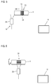
- Fig. 5 shows an embodiment of a sensor device in which on the worm shaft 4 extending in its longitudinal direction, optically scanned code 23, here in the form of a bar code 24 is arranged as an information element 13.
- the sensor element 14 is embodied here as a code or bar code reader 25. If the extruder screw 4 is inserted in the longitudinal direction, the bar code 24 moves through the detection range of the bar code reader 25 and can be detected. The information is in turn given to the control device 11, which then uploads the corresponding operating parameters associated with the information from a memory or directly converts the transmitted operating parameters.
- Fig. 6 finally shows a comparative embodiment of the sensor device, but here the bar code 24 is mounted in the circumferential direction. It is located when the screw 4 is inserted in the detection range of the bar code reader 25 and is detected in a screw rotation.
- the corresponding information elements 13 of whatever kind are of course firmly and permanently connected to the respective extruder screw 4.
- this can be inserted in a corresponding recess on the shaft and cast in it or, since very small-sized, are also superficially placed etc.
- the corresponding metal or magnetic elements 20 can also be superficially placed or introduced into recesses.
- the respective code 23 or barcode 24 can be incorporated directly into the screw material and consequently executed as a height relief or profile. It is also conceivable, however, to arrange a separate information carrier.
Landscapes
- Engineering & Computer Science (AREA)
- Mechanical Engineering (AREA)
- Extrusion Moulding Of Plastics Or The Like (AREA)
- Processing And Handling Of Plastics And Other Materials For Molding In General (AREA)
Priority Applications (1)
| Application Number | Priority Date | Filing Date | Title |
|---|---|---|---|
| PL14176896T PL2845713T3 (pl) | 2013-08-02 | 2014-07-14 | Wytłaczarka ze ślimakiem z automatycznie wykrywanym czujnikiem do przygotowywania informacji charakterystycznych dla jednostki napędowej |
Applications Claiming Priority (1)
| Application Number | Priority Date | Filing Date | Title |
|---|---|---|---|
| DE102013108335.8A DE102013108335B4 (de) | 2013-08-02 | 2013-08-02 | Extruder |
Publications (3)
| Publication Number | Publication Date |
|---|---|
| EP2845713A2 EP2845713A2 (de) | 2015-03-11 |
| EP2845713A3 EP2845713A3 (de) | 2015-04-15 |
| EP2845713B1 true EP2845713B1 (de) | 2016-11-23 |
Family
ID=51176963
Family Applications (1)
| Application Number | Title | Priority Date | Filing Date |
|---|---|---|---|
| EP14176896.0A Active EP2845713B1 (de) | 2013-08-02 | 2014-07-14 | Extruder mit einer Schnecke mit einem automatisch erfassbaren Sensor zur Bereitstellung charakteristischer Informationen für die Antriebseinheit |
Country Status (7)
| Country | Link |
|---|---|
| US (1) | US20150037447A1 (enExample) |
| EP (1) | EP2845713B1 (enExample) |
| CN (1) | CN104339625B (enExample) |
| DE (1) | DE102013108335B4 (enExample) |
| ES (1) | ES2614721T3 (enExample) |
| IN (1) | IN2014MU02438A (enExample) |
| PL (1) | PL2845713T3 (enExample) |
Families Citing this family (14)
| Publication number | Priority date | Publication date | Assignee | Title |
|---|---|---|---|---|
| WO2018067916A1 (en) * | 2016-10-07 | 2018-04-12 | Reed Machinery, Inc. | Cylindrical tool matching system |
| DE102016119868A1 (de) * | 2016-10-18 | 2018-04-19 | Reifenhäuser GmbH & Co. KG Maschinenfabrik | Kunststoff-Extrusionsanlage mit mobiler Nutzerschnittstelle und Verfahren zum Betrieb dieser Kunststoff-Extrusionsanlage |
| DE102018114473A1 (de) * | 2018-06-15 | 2019-12-19 | Battenfeld-Cincinnati Germany Gmbh | Vorrichtung und Verfahren zum Ablängen eines extrudierten Rohres |
| AT522178B1 (de) * | 2019-04-25 | 2020-09-15 | Engel Austria Gmbh | Plastifiziervorrichtung für eine Formgebungsmaschine |
| DE102020101387B4 (de) * | 2020-01-21 | 2022-09-01 | BC Extrusion Holding GmbH | Verfahren und Vorrichtung zum Reduzieren von Schwankungen des Ausstoßes von Kunststoffmasse |
| US11806907B2 (en) | 2020-05-15 | 2023-11-07 | Engel Austria Gmbh | Plasticizing device for a molding machine |
| WO2021255010A1 (de) * | 2020-06-17 | 2021-12-23 | Bühler AG | Extruder und verfahren zur überwachung des zustands eines extruders |
| DE102020117680A1 (de) | 2020-07-03 | 2022-01-05 | Nordson Corporation | Pelletier-Einrichtung zur Herstellung von Polymer-Pellets |
| CN114851518A (zh) * | 2022-03-21 | 2022-08-05 | 广东三优聚合物装备有限公司 | 挤出机用智能操作系统 |
| JP7835602B2 (ja) * | 2022-03-31 | 2026-03-25 | 株式会社日本製鋼所 | スクリュピース組み間違い検出装置、スクリュピース組み間違い検出方法及びコンピュータプログラム |
| JP2023151221A (ja) * | 2022-03-31 | 2023-10-16 | 株式会社日本製鋼所 | スクリュ構成推定装置、スクリュ構成推定方法及びコンピュータプログラム |
| JP2024043389A (ja) * | 2022-09-16 | 2024-03-29 | 住友重機械工業株式会社 | 射出成形機、及び射出成形機の部品 |
| JP2024085514A (ja) | 2022-12-15 | 2024-06-27 | 住友重機械工業株式会社 | 射出成形機 |
| AT527588B1 (de) * | 2024-01-18 | 2025-04-15 | Pro2Future Gmbh | Verfahren zur Bestimmung des axialen Drehmomentenverlaufes in Schneckenextrudern |
Family Cites Families (13)
| Publication number | Priority date | Publication date | Assignee | Title |
|---|---|---|---|---|
| US2019002A (en) * | 1932-06-27 | 1935-10-29 | Drohmann Carl | Machine for packing nutrient fats |
| US4437046A (en) * | 1982-06-18 | 1984-03-13 | Crompton & Knowles Corporation | Extrusion drive control system |
| US4671908A (en) * | 1986-06-26 | 1987-06-09 | Phillips Petroleum Company | Extrusion control process and apparatus |
| US4838700A (en) * | 1987-04-30 | 1989-06-13 | Williamson Kirk E | Assemblies for a worm press |
| DE19744443C1 (de) * | 1997-10-08 | 1998-10-08 | Windmoeller & Hoelscher | Verfahren und Vorrichtung zur Erkennung von bei Extrudern oder Dosiereinrichtungen eingesetzten Schnecken |
| US6347292B1 (en) * | 1999-02-17 | 2002-02-12 | Den-Con Electronics, Inc. | Oilfield equipment identification method and apparatus |
| US7018191B2 (en) * | 2002-08-13 | 2006-03-28 | Harrel Incorporated | Plastics extruder dimension and viscosity control system |
| DE10308386C5 (de) * | 2003-02-27 | 2010-11-04 | Sumitomo (Shi) Demag Plastics Machinery Gmbh | Identifikation von modularen Maschinenanbauteilen |
| AT7303U1 (de) * | 2003-09-10 | 2005-01-25 | Engel Austria Gmbh | Spritzgiessmaschine |
| DE102005014941B4 (de) * | 2005-04-01 | 2009-02-26 | Kraussmaffei Technologies Gmbh | Verfahren zum Bereitstellen von Dokumentationsinformationen von komplexen Maschinen und Anlagen, insbesondere einer Spritzgussmaschine |
| CN2827694Y (zh) * | 2005-09-02 | 2006-10-18 | 杨群发 | 生物质螺杆成型机主机 |
| JP4491011B2 (ja) * | 2007-11-28 | 2010-06-30 | 株式会社神戸製鋼所 | 混練処理装置の負荷監視方法及び負荷監視装置 |
| DE102009007559B4 (de) * | 2009-02-04 | 2017-07-06 | Sew-Eurodrive Gmbh & Co Kg | Antriebssystem, Mehrfachantriebssystem, Verfahren zum Überprüfen eines Antriebssystems oder Mehrfachantriebssystems, Verfahren zur Inbetriebnahme einer Maschine, Maschine mit einem Antriebssystem oder Mehrfachantriebssystem, Computerprogramm und –produkt |
-
2013
- 2013-08-02 DE DE102013108335.8A patent/DE102013108335B4/de active Active
-
2014
- 2014-07-14 EP EP14176896.0A patent/EP2845713B1/de active Active
- 2014-07-14 ES ES14176896.0T patent/ES2614721T3/es active Active
- 2014-07-14 PL PL14176896T patent/PL2845713T3/pl unknown
- 2014-07-28 IN IN2438MU2014 patent/IN2014MU02438A/en unknown
- 2014-07-31 CN CN201410374807.1A patent/CN104339625B/zh active Active
- 2014-08-01 US US14/449,791 patent/US20150037447A1/en not_active Abandoned
Non-Patent Citations (1)
Also Published As
| Publication number | Publication date |
|---|---|
| US20150037447A1 (en) | 2015-02-05 |
| CN104339625B (zh) | 2017-04-12 |
| DE102013108335A1 (de) | 2015-02-05 |
| CN104339625A (zh) | 2015-02-11 |
| DE102013108335B4 (de) | 2017-06-22 |
| EP2845713A3 (de) | 2015-04-15 |
| IN2014MU02438A (enExample) | 2015-10-09 |
| ES2614721T3 (es) | 2017-06-01 |
| PL2845713T3 (pl) | 2017-06-30 |
| EP2845713A2 (de) | 2015-03-11 |
Similar Documents
| Publication | Publication Date | Title |
|---|---|---|
| EP2845713B1 (de) | Extruder mit einer Schnecke mit einem automatisch erfassbaren Sensor zur Bereitstellung charakteristischer Informationen für die Antriebseinheit | |
| DE10308386B4 (de) | Identifikation von modularen Maschinenanbauteilen | |
| EP2597310B1 (de) | Verfahren zum Betreiben einer drehzahlvariablen Verstellpumpe | |
| DE3249092T1 (de) | Spritzgussmaschine | |
| DE19732622A1 (de) | Vorrichtung und Verfahren zum Betreiben einer Gießmaschine | |
| EP1483092B1 (de) | Verfahren und vorrichtung zur einstellung einer vorspannung der messer einer granuliervorrichtung | |
| DE60313557T2 (de) | Doppeltwirkende, hydraulische Presse | |
| DE102013112971B3 (de) | Einrichtung und Verfahren zur Überprüfung des Aufbaus einer Extruderschnecke | |
| EP3291945B1 (de) | Vorrichtung zur minimalmengenschmierung | |
| EP3403783B1 (de) | Temperatur-überwachungseinrichtung für werkzeugspindeln sowie verfahren unter verwendung einer temperatur-überwachungseinrichtung | |
| DE102016101523B4 (de) | System und Verfahren zum Spritzgießen von Kunststoffen | |
| EP3749493B1 (de) | Vorrichtung und verfahren zum ablängen eines extrudierten rohres | |
| DE10330193B3 (de) | Spritzgießmaschine mit Kraftsensor | |
| DE102006017496B4 (de) | Steuervorrichtung zur Verwendung in einer Spritzgussmaschine | |
| DE102016108623A1 (de) | Verfahren zum Beeinflussen einer Vorrichtung zum Spritzgießen von Kunststoffen | |
| DE102024108736B4 (de) | Verwaltungsvorrichtung für spritzgiessmaschine, spritzgiessmaschine und verwaltungsverfahren für spritzgiessmaschine | |
| DE102014226620A1 (de) | Verfahren und Vorrichtung zur Parametrierung zumindest einer Komponente einer elektrohydraulischen Antriebseinheit | |
| DE69810883T2 (de) | Antriebsmechanismus für plunger von metallformen in einer glasflaschenformmaschine | |
| DE102022133543A1 (de) | Steuervorrichtung für spritzgiessmaschine | |
| EP0171609A2 (de) | Einrichtung zur Steuerung und/oder Begrenzung der Formauftriebskraft an Spritzgiessmaschinen | |
| DE10312799A1 (de) | Verfahren und Vorrichtung zum Überwachen einer zugeführten Länge eines Materials | |
| EP2255945A1 (de) | Elektrisch betriebene hydraulische Antriebseinrichtung als Nebenaggregat für eine Spritzgießmaschine | |
| WO2006042491A2 (de) | Einwellige, kontinuerlich arbeitende misch- und kraftmaschine mit konischem schaft | |
| DE112021001055T5 (de) | SPRITZGIEßMASCHINENSYSTEM UND SPRITZGIEßMASCHINE | |
| EP1953880B1 (de) | Crimpvorrichtung |
Legal Events
| Date | Code | Title | Description |
|---|---|---|---|
| 17P | Request for examination filed |
Effective date: 20140714 |
|
| AK | Designated contracting states |
Kind code of ref document: A2 Designated state(s): AL AT BE BG CH CY CZ DE DK EE ES FI FR GB GR HR HU IE IS IT LI LT LU LV MC MK MT NL NO PL PT RO RS SE SI SK SM TR |
|
| AX | Request for extension of the european patent |
Extension state: BA ME |
|
| PUAI | Public reference made under article 153(3) epc to a published international application that has entered the european phase |
Free format text: ORIGINAL CODE: 0009012 |
|
| PUAL | Search report despatched |
Free format text: ORIGINAL CODE: 0009013 |
|
| AK | Designated contracting states |
Kind code of ref document: A3 Designated state(s): AL AT BE BG CH CY CZ DE DK EE ES FI FR GB GR HR HU IE IS IT LI LT LU LV MC MK MT NL NO PL PT RO RS SE SI SK SM TR |
|
| AX | Request for extension of the european patent |
Extension state: BA ME |
|
| RIC1 | Information provided on ipc code assigned before grant |
Ipc: B29C 47/92 20060101ALI20150309BHEP Ipc: B29C 47/60 20060101ALI20150309BHEP Ipc: B29C 47/08 20060101AFI20150309BHEP Ipc: B29C 47/96 20060101ALN20150309BHEP |
|
| R17P | Request for examination filed (corrected) |
Effective date: 20151012 |
|
| RBV | Designated contracting states (corrected) |
Designated state(s): AL AT BE BG CH CY CZ DE DK EE ES FI FR GB GR HR HU IE IS IT LI LT LU LV MC MK MT NL NO PL PT RO RS SE SI SK SM TR |
|
| 17Q | First examination report despatched |
Effective date: 20160204 |
|
| GRAP | Despatch of communication of intention to grant a patent |
Free format text: ORIGINAL CODE: EPIDOSNIGR1 |
|
| RIC1 | Information provided on ipc code assigned before grant |
Ipc: B29C 47/92 20060101ALI20160726BHEP Ipc: B29C 47/08 20060101AFI20160726BHEP Ipc: B29C 47/60 20060101ALI20160726BHEP Ipc: B29C 47/96 20060101ALN20160726BHEP |
|
| INTG | Intention to grant announced |
Effective date: 20160808 |
|
| GRAS | Grant fee paid |
Free format text: ORIGINAL CODE: EPIDOSNIGR3 |
|
| GRAA | (expected) grant |
Free format text: ORIGINAL CODE: 0009210 |
|
| AK | Designated contracting states |
Kind code of ref document: B1 Designated state(s): AL AT BE BG CH CY CZ DE DK EE ES FI FR GB GR HR HU IE IS IT LI LT LU LV MC MK MT NL NO PL PT RO RS SE SI SK SM TR |
|
| REG | Reference to a national code |
Ref country code: GB Ref legal event code: FG4D Free format text: NOT ENGLISH |
|
| REG | Reference to a national code |
Ref country code: CH Ref legal event code: EP |
|
| REG | Reference to a national code |
Ref country code: IE Ref legal event code: FG4D Free format text: LANGUAGE OF EP DOCUMENT: GERMAN |
|
| REG | Reference to a national code |
Ref country code: AT Ref legal event code: REF Ref document number: 847465 Country of ref document: AT Kind code of ref document: T Effective date: 20161215 |
|
| REG | Reference to a national code |
Ref country code: DE Ref legal event code: R096 Ref document number: 502014002025 Country of ref document: DE |
|
| REG | Reference to a national code |
Ref country code: NL Ref legal event code: FP |
|
| PG25 | Lapsed in a contracting state [announced via postgrant information from national office to epo] |
Ref country code: LV Free format text: LAPSE BECAUSE OF FAILURE TO SUBMIT A TRANSLATION OF THE DESCRIPTION OR TO PAY THE FEE WITHIN THE PRESCRIBED TIME-LIMIT Effective date: 20161123 |
|
| REG | Reference to a national code |
Ref country code: LT Ref legal event code: MG4D |
|
| PG25 | Lapsed in a contracting state [announced via postgrant information from national office to epo] |
Ref country code: SE Free format text: LAPSE BECAUSE OF FAILURE TO SUBMIT A TRANSLATION OF THE DESCRIPTION OR TO PAY THE FEE WITHIN THE PRESCRIBED TIME-LIMIT Effective date: 20161123 Ref country code: NO Free format text: LAPSE BECAUSE OF FAILURE TO SUBMIT A TRANSLATION OF THE DESCRIPTION OR TO PAY THE FEE WITHIN THE PRESCRIBED TIME-LIMIT Effective date: 20170223 Ref country code: LT Free format text: LAPSE BECAUSE OF FAILURE TO SUBMIT A TRANSLATION OF THE DESCRIPTION OR TO PAY THE FEE WITHIN THE PRESCRIBED TIME-LIMIT Effective date: 20161123 Ref country code: GR Free format text: LAPSE BECAUSE OF FAILURE TO SUBMIT A TRANSLATION OF THE DESCRIPTION OR TO PAY THE FEE WITHIN THE PRESCRIBED TIME-LIMIT Effective date: 20170224 |
|
| PG25 | Lapsed in a contracting state [announced via postgrant information from national office to epo] |
Ref country code: RS Free format text: LAPSE BECAUSE OF FAILURE TO SUBMIT A TRANSLATION OF THE DESCRIPTION OR TO PAY THE FEE WITHIN THE PRESCRIBED TIME-LIMIT Effective date: 20161123 Ref country code: FI Free format text: LAPSE BECAUSE OF FAILURE TO SUBMIT A TRANSLATION OF THE DESCRIPTION OR TO PAY THE FEE WITHIN THE PRESCRIBED TIME-LIMIT Effective date: 20161123 Ref country code: PT Free format text: LAPSE BECAUSE OF FAILURE TO SUBMIT A TRANSLATION OF THE DESCRIPTION OR TO PAY THE FEE WITHIN THE PRESCRIBED TIME-LIMIT Effective date: 20170323 Ref country code: HR Free format text: LAPSE BECAUSE OF FAILURE TO SUBMIT A TRANSLATION OF THE DESCRIPTION OR TO PAY THE FEE WITHIN THE PRESCRIBED TIME-LIMIT Effective date: 20161123 |
|
| REG | Reference to a national code |
Ref country code: ES Ref legal event code: FG2A Ref document number: 2614721 Country of ref document: ES Kind code of ref document: T3 Effective date: 20170601 |
|
| REG | Reference to a national code |
Ref country code: FR Ref legal event code: PLFP Year of fee payment: 4 |
|
| PG25 | Lapsed in a contracting state [announced via postgrant information from national office to epo] |
Ref country code: SK Free format text: LAPSE BECAUSE OF FAILURE TO SUBMIT A TRANSLATION OF THE DESCRIPTION OR TO PAY THE FEE WITHIN THE PRESCRIBED TIME-LIMIT Effective date: 20161123 Ref country code: EE Free format text: LAPSE BECAUSE OF FAILURE TO SUBMIT A TRANSLATION OF THE DESCRIPTION OR TO PAY THE FEE WITHIN THE PRESCRIBED TIME-LIMIT Effective date: 20161123 Ref country code: DK Free format text: LAPSE BECAUSE OF FAILURE TO SUBMIT A TRANSLATION OF THE DESCRIPTION OR TO PAY THE FEE WITHIN THE PRESCRIBED TIME-LIMIT Effective date: 20161123 Ref country code: RO Free format text: LAPSE BECAUSE OF FAILURE TO SUBMIT A TRANSLATION OF THE DESCRIPTION OR TO PAY THE FEE WITHIN THE PRESCRIBED TIME-LIMIT Effective date: 20161123 |
|
| REG | Reference to a national code |
Ref country code: DE Ref legal event code: R097 Ref document number: 502014002025 Country of ref document: DE |
|
| PG25 | Lapsed in a contracting state [announced via postgrant information from national office to epo] |
Ref country code: BG Free format text: LAPSE BECAUSE OF FAILURE TO SUBMIT A TRANSLATION OF THE DESCRIPTION OR TO PAY THE FEE WITHIN THE PRESCRIBED TIME-LIMIT Effective date: 20170223 Ref country code: SM Free format text: LAPSE BECAUSE OF FAILURE TO SUBMIT A TRANSLATION OF THE DESCRIPTION OR TO PAY THE FEE WITHIN THE PRESCRIBED TIME-LIMIT Effective date: 20161123 |
|
| PLBE | No opposition filed within time limit |
Free format text: ORIGINAL CODE: 0009261 |
|
| STAA | Information on the status of an ep patent application or granted ep patent |
Free format text: STATUS: NO OPPOSITION FILED WITHIN TIME LIMIT |
|
| 26N | No opposition filed |
Effective date: 20170824 |
|
| PG25 | Lapsed in a contracting state [announced via postgrant information from national office to epo] |
Ref country code: SI Free format text: LAPSE BECAUSE OF FAILURE TO SUBMIT A TRANSLATION OF THE DESCRIPTION OR TO PAY THE FEE WITHIN THE PRESCRIBED TIME-LIMIT Effective date: 20161123 |
|
| REG | Reference to a national code |
Ref country code: CH Ref legal event code: PL |
|
| REG | Reference to a national code |
Ref country code: IE Ref legal event code: MM4A |
|
| PG25 | Lapsed in a contracting state [announced via postgrant information from national office to epo] |
Ref country code: LI Free format text: LAPSE BECAUSE OF NON-PAYMENT OF DUE FEES Effective date: 20170731 Ref country code: CH Free format text: LAPSE BECAUSE OF NON-PAYMENT OF DUE FEES Effective date: 20170731 Ref country code: IE Free format text: LAPSE BECAUSE OF NON-PAYMENT OF DUE FEES Effective date: 20170714 |
|
| REG | Reference to a national code |
Ref country code: BE Ref legal event code: MM Effective date: 20170731 |
|
| PG25 | Lapsed in a contracting state [announced via postgrant information from national office to epo] |
Ref country code: LU Free format text: LAPSE BECAUSE OF NON-PAYMENT OF DUE FEES Effective date: 20170714 |
|
| REG | Reference to a national code |
Ref country code: FR Ref legal event code: PLFP Year of fee payment: 5 |
|
| PG25 | Lapsed in a contracting state [announced via postgrant information from national office to epo] |
Ref country code: BE Free format text: LAPSE BECAUSE OF NON-PAYMENT OF DUE FEES Effective date: 20170731 |
|
| PG25 | Lapsed in a contracting state [announced via postgrant information from national office to epo] |
Ref country code: MT Free format text: LAPSE BECAUSE OF FAILURE TO SUBMIT A TRANSLATION OF THE DESCRIPTION OR TO PAY THE FEE WITHIN THE PRESCRIBED TIME-LIMIT Effective date: 20161123 |
|
| REG | Reference to a national code |
Ref country code: DE Ref legal event code: R079 Ref document number: 502014002025 Country of ref document: DE Free format text: PREVIOUS MAIN CLASS: B29C0047080000 Ipc: B29C0048250000 |
|
| PG25 | Lapsed in a contracting state [announced via postgrant information from national office to epo] |
Ref country code: MC Free format text: LAPSE BECAUSE OF FAILURE TO SUBMIT A TRANSLATION OF THE DESCRIPTION OR TO PAY THE FEE WITHIN THE PRESCRIBED TIME-LIMIT Effective date: 20161123 Ref country code: HU Free format text: LAPSE BECAUSE OF FAILURE TO SUBMIT A TRANSLATION OF THE DESCRIPTION OR TO PAY THE FEE WITHIN THE PRESCRIBED TIME-LIMIT; INVALID AB INITIO Effective date: 20140714 |
|
| PG25 | Lapsed in a contracting state [announced via postgrant information from national office to epo] |
Ref country code: CY Free format text: LAPSE BECAUSE OF FAILURE TO SUBMIT A TRANSLATION OF THE DESCRIPTION OR TO PAY THE FEE WITHIN THE PRESCRIBED TIME-LIMIT Effective date: 20161123 |
|
| PG25 | Lapsed in a contracting state [announced via postgrant information from national office to epo] |
Ref country code: MK Free format text: LAPSE BECAUSE OF FAILURE TO SUBMIT A TRANSLATION OF THE DESCRIPTION OR TO PAY THE FEE WITHIN THE PRESCRIBED TIME-LIMIT Effective date: 20161123 |
|
| PG25 | Lapsed in a contracting state [announced via postgrant information from national office to epo] |
Ref country code: IS Free format text: LAPSE BECAUSE OF FAILURE TO SUBMIT A TRANSLATION OF THE DESCRIPTION OR TO PAY THE FEE WITHIN THE PRESCRIBED TIME-LIMIT Effective date: 20170323 Ref country code: AL Free format text: LAPSE BECAUSE OF FAILURE TO SUBMIT A TRANSLATION OF THE DESCRIPTION OR TO PAY THE FEE WITHIN THE PRESCRIBED TIME-LIMIT Effective date: 20161123 |
|
| P01 | Opt-out of the competence of the unified patent court (upc) registered |
Effective date: 20230506 |
|
| PGFP | Annual fee paid to national office [announced via postgrant information from national office to epo] |
Ref country code: NL Payment date: 20250723 Year of fee payment: 12 |
|
| PGFP | Annual fee paid to national office [announced via postgrant information from national office to epo] |
Ref country code: ES Payment date: 20250819 Year of fee payment: 12 |
|
| PGFP | Annual fee paid to national office [announced via postgrant information from national office to epo] |
Ref country code: DE Payment date: 20250623 Year of fee payment: 12 |
|
| PGFP | Annual fee paid to national office [announced via postgrant information from national office to epo] |
Ref country code: PL Payment date: 20250707 Year of fee payment: 12 Ref country code: TR Payment date: 20250708 Year of fee payment: 12 Ref country code: IT Payment date: 20250731 Year of fee payment: 12 |
|
| PGFP | Annual fee paid to national office [announced via postgrant information from national office to epo] |
Ref country code: GB Payment date: 20250724 Year of fee payment: 12 |
|
| PGFP | Annual fee paid to national office [announced via postgrant information from national office to epo] |
Ref country code: FR Payment date: 20250723 Year of fee payment: 12 Ref country code: AT Payment date: 20250721 Year of fee payment: 12 |
|
| PGFP | Annual fee paid to national office [announced via postgrant information from national office to epo] |
Ref country code: CZ Payment date: 20250701 Year of fee payment: 12 |