EP2845528A2 - Multipurpose cooking appliance - Google Patents
Multipurpose cooking appliance Download PDFInfo
- Publication number
- EP2845528A2 EP2845528A2 EP14180449.2A EP14180449A EP2845528A2 EP 2845528 A2 EP2845528 A2 EP 2845528A2 EP 14180449 A EP14180449 A EP 14180449A EP 2845528 A2 EP2845528 A2 EP 2845528A2
- Authority
- EP
- European Patent Office
- Prior art keywords
- multisided
- cooking
- cooking appliance
- appliance according
- base
- Prior art date
- Legal status (The legal status is an assumption and is not a legal conclusion. Google has not performed a legal analysis and makes no representation as to the accuracy of the status listed.)
- Granted
Links
Images


Classifications
-
- A—HUMAN NECESSITIES
- A47—FURNITURE; DOMESTIC ARTICLES OR APPLIANCES; COFFEE MILLS; SPICE MILLS; SUCTION CLEANERS IN GENERAL
- A47J—KITCHEN EQUIPMENT; COFFEE MILLS; SPICE MILLS; APPARATUS FOR MAKING BEVERAGES
- A47J37/00—Baking; Roasting; Grilling; Frying
- A47J37/06—Roasters; Grills; Sandwich grills
- A47J37/0623—Small-size cooking ovens, i.e. defining an at least partially closed cooking cavity
- A47J37/0647—Small-size cooking ovens, i.e. defining an at least partially closed cooking cavity with gas burners
-
- A—HUMAN NECESSITIES
- A47—FURNITURE; DOMESTIC ARTICLES OR APPLIANCES; COFFEE MILLS; SPICE MILLS; SUCTION CLEANERS IN GENERAL
- A47J—KITCHEN EQUIPMENT; COFFEE MILLS; SPICE MILLS; APPARATUS FOR MAKING BEVERAGES
- A47J37/00—Baking; Roasting; Grilling; Frying
- A47J37/06—Roasters; Grills; Sandwich grills
- A47J37/0623—Small-size cooking ovens, i.e. defining an at least partially closed cooking cavity
- A47J37/0658—Small-size cooking ovens, i.e. defining an at least partially closed cooking cavity specially adapted for cooking pizza
-
- A—HUMAN NECESSITIES
- A47—FURNITURE; DOMESTIC ARTICLES OR APPLIANCES; COFFEE MILLS; SPICE MILLS; SUCTION CLEANERS IN GENERAL
- A47J—KITCHEN EQUIPMENT; COFFEE MILLS; SPICE MILLS; APPARATUS FOR MAKING BEVERAGES
- A47J37/00—Baking; Roasting; Grilling; Frying
- A47J37/06—Roasters; Grills; Sandwich grills
- A47J37/07—Roasting devices for outdoor use; Barbecues
- A47J37/0704—Roasting devices for outdoor use; Barbecues with horizontal fire box
- A47J37/0713—Roasting devices for outdoor use; Barbecues with horizontal fire box with gas burners
-
- F—MECHANICAL ENGINEERING; LIGHTING; HEATING; WEAPONS; BLASTING
- F24—HEATING; RANGES; VENTILATING
- F24B—DOMESTIC STOVES OR RANGES FOR SOLID FUELS; IMPLEMENTS FOR USE IN CONNECTION WITH STOVES OR RANGES
- F24B1/00—Stoves or ranges
- F24B1/20—Ranges
- F24B1/22—Ranges in which the baking oven is arranged above the fire-box
-
- F—MECHANICAL ENGINEERING; LIGHTING; HEATING; WEAPONS; BLASTING
- F24—HEATING; RANGES; VENTILATING
- F24C—DOMESTIC STOVES OR RANGES ; DETAILS OF DOMESTIC STOVES OR RANGES, OF GENERAL APPLICATION
- F24C1/00—Stoves or ranges in which the fuel or energy supply is not restricted to solid fuel or to a type covered by a single one of the following groups F24C3/00 - F24C9/00; Stoves or ranges in which the type of fuel or energy supply is not specified
- F24C1/02—Stoves or ranges in which the fuel or energy supply is not restricted to solid fuel or to a type covered by a single one of the following groups F24C3/00 - F24C9/00; Stoves or ranges in which the type of fuel or energy supply is not specified adapted for the use of two or more kinds of fuel or energy supply
-
- F—MECHANICAL ENGINEERING; LIGHTING; HEATING; WEAPONS; BLASTING
- F24—HEATING; RANGES; VENTILATING
- F24C—DOMESTIC STOVES OR RANGES ; DETAILS OF DOMESTIC STOVES OR RANGES, OF GENERAL APPLICATION
- F24C15/00—Details
- F24C15/16—Shelves, racks or trays inside ovens; Supports therefor
-
- Y—GENERAL TAGGING OF NEW TECHNOLOGICAL DEVELOPMENTS; GENERAL TAGGING OF CROSS-SECTIONAL TECHNOLOGIES SPANNING OVER SEVERAL SECTIONS OF THE IPC; TECHNICAL SUBJECTS COVERED BY FORMER USPC CROSS-REFERENCE ART COLLECTIONS [XRACs] AND DIGESTS
- Y02—TECHNOLOGIES OR APPLICATIONS FOR MITIGATION OR ADAPTATION AGAINST CLIMATE CHANGE
- Y02A—TECHNOLOGIES FOR ADAPTATION TO CLIMATE CHANGE
- Y02A40/00—Adaptation technologies in agriculture, forestry, livestock or agroalimentary production
- Y02A40/90—Adaptation technologies in agriculture, forestry, livestock or agroalimentary production in food processing or handling, e.g. food conservation
- Y02A40/924—Adaptation technologies in agriculture, forestry, livestock or agroalimentary production in food processing or handling, e.g. food conservation using renewable energies
- Y02A40/928—Cooking stoves using biomass
Definitions
- This invention relates generally to the art of appliances or equipment used for cooking food of the type generally known as ovens, grills, and smokers, and, in particular, to appliances capable of cooking in any of several ways, separately or simultaneously.
- an oven generally has a heated chamber that receives the food to be cooked.
- the source of heat can be, for example, an electric heater, a gas burner, charcoal, or wood.
- cooking appliances can be grills using any of these sources of heat as well as smokers that use these sources and also a source of smoke, such as wood chips.
- Each type of cooking appliance has unique characteristics, and a chef chooses a particular appliance for that reason. Because a homeowner or even a small restaurant is typically unable to afford several different cooking appliances, the only type of food available will be determined by the particular appliance available. Accordingly, a need exists for a cooking appliance that can easily be converted from one type of cooking appliance to another.
- the cooking appliance of the invention provides several types of cooking structures and can be converted from one to another easily.
- a cooking appliance can be converted from an oven to a grill.
- the appliance provides an oven, a gas-fired grill, a charcoal grill, or a smoker and can be converted from one to another or in some instances use more than one type simultaneously.
- the cooking appliance of the invention includes a multisided element that provides a grill on one side and an oven surface, such as brick, on another side.
- the multisided element can be mounted on a base by structure that allows it to be oriented to present the particular cooking surface desired.
- the various cooking surfaces can be elongated and arranged to form a multisided element with the various cooking surfaces placed about a longitudinal axis whereby a particular cooking surface can be presented by rotating the multisided element.
- the multisided elements can be geometrically prisms with each cooking surface being rectangular and the surfaces being arranged about a central longitudinal axis.
- Such a multisided element can be mounted on structure that allows it to rotate so that it is easily rotated to select the desired cooking surface.
- the element can be held by structure that holds it securely but which will receive it in any of several orientations to present the desired surface. If the desired cooking surfaces are not flat other configurations can be used.
- two or more of the multisided elements are provided adjacent each other so that the cooking surface is formed by plural but closely adjacent surfaces.
- the multisided elements are mounted for rotation they are also preferably mounted to structure that allows them to move away from each other horizontally to provide space between them to allow rotation. After the multisided elements have been rotated to present the desired surfaces, they are moved toward each other so the surfaces are close to each other and present a continuous cooking surface.
- a grill type surface can be provided with a pan just below the surface to hold a source of heat such as wood or charcoal for grilling.
- part of the pan can be provided with a source of smoke for smoking foods, such as meats or vegetables.
- a cover can be provided only over a portion of the cooking surface.
- a cover can be provided in sections so that any selected part of a surface can be covered.
- a gas burner is a common source of heat, and in the invention a gas burner can be provided within the multisided element.
- a gas burner can be mounted to lie on the longitudinal axis of the multisided element to provide heat to at least the surface that has been moved into a cooking orientation.
- a gas burner can be located above the multisided element to provide a source of heat to the top of a cooking surface. This structure is particularly advantageous when using the appliance of the invention as an oven.
- FIG. 1 (a) illustrates a cooking appliance 2 in accordance with an embodiment of the invention.
- Appliance 2 includes a base 4, which is mounted on casters 6 for convenience, as known in the art.
- the base 2 supports two multisided elements, which will be described in detail below.
- the multisided elements are oriented to present an oven surface 8, a grill surface 9, and a smoker surface 11.
- the oven surface 8 is made of bricks that are capable of use at high temperatures, such as those typical in ovens used for cooking pizza.
- the appliance 2 includes a multipart lid 10 that can cover the cooking surface to form a heated chamber when the appliance is used as an oven as shown in figure 1 (a) , as a smoker as shown in figures 1 (b) and 1 (d) , or in other configurations as selected by the user.
- the lid 10 is preferably provided in at least two sections and is mounted to the base so the sections can be moved from the cooking surfaces (e.g., 8, 9, and 11) for providing access to the cooking surfaces. While the lid can be mounted by hinges to allow pivotal movement, in the embodiment shown it is attached by a sliding mechanism to provide flexibility in configuring the appliance for various cooking environments.
- a handle 44 may be provided to allow the user to move the front section forward and rearward.
- the lid 10 is generally cylindrical, but it may be in other shapes.
- the lid illustrated includes a front section 30 and a rear section 32.
- the radius of the front section 30 is slightly larger than that of the rear section to allow the front section to slide over the rear section, as illustrated in figure 1 (b) .
- the appliance may be provided with any of several known mechanisms to mount the front section 30 for movement rearward as illustrated, and in the embodiment shown, the upper surface is provides with grooves that receive cooperating structure on the lid (not shown) to facilitate the movement.
- each of the sections 30, 32 includes a chimney to control movement of air out of the chamber formed by the lid, and each chimney has an adjustable damper (not shown).
- the rear section 32 can also have a door 38 to allow access to the interior of the chamber as illustrated in figure 1 (c) .
- Figure 1 (d) shows an embodiment where the front section 30 has been removed (or not provided) and a portable front cover 40 placed on the front of the rear section 32 to provide a completely enclosed cavity.
- a cover 40 can also be used in any of the embodiments shown in figures 1(a) , 1(b) , or 1(c) .
- This configuration is particularly advantageous when cooking food by the process of smoking.
- the smoker surface 11 (see figure 1 (b) ) is provided with wood chips or another source of smoke and heat, and the food is placed on the oven surface 8.
- the cavity is closed by the cover 40, and the air flow is controlled by a damper in the chimney 36.
- the grill surface 9 can be used to grill other pieces of food.
- Figure 1 (a) also shows a cavity 42 in the base for storing such articles as wood conveniently.
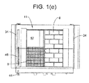
- Figure 1 (e) is a top view of the upper surface of the appliance, with the lid removed, to illustrate several of the cooking surfaces contemplated. Additionally, figure 1 (e) illustrates the provision of a gas burner 46 adjacent the cooking surface. This burner can be used to heat the cavity formed by the lid, as for cooking pizzas. As well, wood can be placed on the surface 11 or 8 to heat the cavity.
- Figure 1 (e) also shows the feature of the invention wherein a pan 52 is placed under a selected surface, such as a grill surface illustrated in figure 1 (e) that is to be used with wood as a source of heat or a smoker surface 11 that will be supplied with wood, or wood chips.
- the pan 52 is held under the grill 9 and open space 11, as in figure 1 (e) but the pan can be used for any of the surfaces that require a source of heat below a surface other than that provided by the centrally located gas burner 48 (see figure 4 ).
- FIG. 2 illustrates one embodiment of the invention wherein a first multisided element 12 is mounted adjacent a second multisided element 14 on a support 16.
- Each side of the multisided elements provides a different cooking surface.
- one side can be an oven surface made of high temperature brick.
- Another of the surfaces can be a flat griddle for frying.
- Another of the surfaces can be a grill.
- Various other desirable surfaces will be apparent to those of skill in the art.
- the support 16 includes a frame 18, which is attached to the base 4, and also includes vertical mounting plates 20.
- the vertical mounting plates are preferably provided in pairs, with each mounted on a respective side of the frame 18 to support between them a multisided element 12 or 14.
- the multisided elements are attached to the mounting plates for rotation with respect to the plates so each can be rotated about a longitudinal axis extending between a respective pair of mounting plates.
- the mounting plates 20 are shown in the drawings as flat and rectangular, it will be appreciated that their primary function is to support the multisided elements and to allow them to rotate. Thus, they can be almost any kind of support structure including, for example, brackets, pillars, etc.
- Figure 3 illustrates the feature of the invention that the multisided elements 12 and 14 can be rotated to present a desired one of the surfaces to the user.
- the multisided elements shown in figure 3 are illustrated in positions mid-way between changing from a bricked oven surface to a grate. This is easily accomplished in the embodiment shown because the multisided elements 12 and 14 are mounted on the plates 20 by rotational mounting structures 24, which can be bearings or other known structures that support the multisided elements securely while allowing them to be rotated.
- rotational drive mechanisms 26 by which a user can rotate the multisided elements to present different surfaces.
- the drive mechanisms 26 illustrated include handles, each of which rotates a respective shaft in response to rotation by the user.
- the shaft can be connected to the multisided element by a gear mechanism (not shown) or by a flexible belt (not shown), or by any of several other known mechanisms.
- the vertical plates 20 are also mounted to the frame 18 for lateral movement to provide spacing between the multisided elements during their rotation.
- a separating mechanism 28 is provided so the user can move the multisided elements away from each other to permit rotation of the multisided elements and then to bring them back together for cooking.
- the separating mechanism can be any of several known mechanisms, such as a shaft with a pinion gear (not shown) that engages racks (not shown) attached to the mounting plates to move the mounting plates and the associated multisided elements linearly toward or away from each in response to rotation of the handle 28.
- Other mechanisms may be used, including electric motors, scissors-type mechanisms, or even manual sliding mechanisms.
- One source of heat useful with the invention is a known gas burner.
- a known gas burner can take any of several forms and can be located in several locations.
- the burner is the familiar tube with openings for the gas, and the tube is supported by the vertical plates 20 to lie along the longitudinal axis of a multisided element.
- Figure 4 illustrates such an arrangement, where gas burners 48 are located on respective longitudinal axes of the multisided elements and are provided with gas via a known tank 51.
- Other sources of heat such as those discussed above and others, as determined by the user, can be used.
- FIG. 5 shows an embodiment of the invention where the cooking appliance is in the shape of a commercial pizza oven 54, which is mounted on a stand 55.
- the usual pizza oven of the type shown has a dome made of bricks to form a cavity for receiving the food to be cooked, the cavity having a brick floor (not shown).
- the outer surface of the dome is typically covered with a decorative design made of ceramic elements.
- An opening 56 is provided through which food is passed into or out of the cooking cavity.
- the oven 54 is provided with a door 58 that is mounted to the oven 54 so that it can be moved to expose one or more multisided elements, such as the multisided element 12 described above.
- the door is mounted to the oven by a hinge that allows it to be pivoted away from the oven 54.
- the door may be mounted to the oven in other ways, however.
- the door 58 can be mounted on the oven by sliding elements that allow the door to be pulled outwardly away from the oven, horizontally or vertically, or provided with hinges to allow it to be pivoted upward or downward, as well as by other structures.
- the door 58 is shown after being pivoted away from the front of the oven to expose a multisided element 12.
- the multisided element can be mounted to the oven by an extendible element 60 that allows the multisided element to be pulled out of the oven for rotation.
- the extendible element can be a telescoping element or it can be of fixed length and carried by brackets, if the diameter of the oven is adequate to receive the element when the multisided element is pushed back into the oven cavity.
- the multisided element can be supported by the oven in a variety of other ways and can be separable from the oven, if it is small enough to allow al person to pull it out, rotate it, and slide it back into the oven.
- Figure 6 shows the multisided element with a grill surface at the top
- figure 7 shows the multisided element during rotation
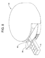
- figure 8 shows it after rotation to orient a brick surface at the top. After rotation to place the desired surface at the top, for example, as in figure 8 , the multisided element is then moved back into the cooking cavity.
- the multisided element 12 shown in figures 5 through 8 can be provided with wood chips for smoking, charcoal for heating from below, or heat from a gas burner as described above.
Landscapes
- Engineering & Computer Science (AREA)
- Chemical & Material Sciences (AREA)
- Combustion & Propulsion (AREA)
- Food Science & Technology (AREA)
- Mechanical Engineering (AREA)
- General Engineering & Computer Science (AREA)
- Baking, Grill, Roasting (AREA)
Abstract


Description
- This application claims priority of United States provisional application serial number
61/866,573 - This invention relates generally to the art of appliances or equipment used for cooking food of the type generally known as ovens, grills, and smokers, and, in particular, to appliances capable of cooking in any of several ways, separately or simultaneously.
- Many different types of cooking appliances are known. For example, an oven generally has a heated chamber that receives the food to be cooked. The source of heat can be, for example, an electric heater, a gas burner, charcoal, or wood. As well, cooking appliances can be grills using any of these sources of heat as well as smokers that use these sources and also a source of smoke, such as wood chips.
- Each type of cooking appliance has unique characteristics, and a chef chooses a particular appliance for that reason. Because a homeowner or even a small restaurant is typically unable to afford several different cooking appliances, the only type of food available will be determined by the particular appliance available. Accordingly, a need exists for a cooking appliance that can easily be converted from one type of cooking appliance to another.
- The cooking appliance of the invention provides several types of cooking structures and can be converted from one to another easily. In one embodiment a cooking appliance can be converted from an oven to a grill. In another embodiment the appliance provides an oven, a gas-fired grill, a charcoal grill, or a smoker and can be converted from one to another or in some instances use more than one type simultaneously.
- In one embodiment the cooking appliance of the invention includes a multisided element that provides a grill on one side and an oven surface, such as brick, on another side. The multisided element can be mounted on a base by structure that allows it to be oriented to present the particular cooking surface desired. For example, the various cooking surfaces can be elongated and arranged to form a multisided element with the various cooking surfaces placed about a longitudinal axis whereby a particular cooking surface can be presented by rotating the multisided element. Because the cooking surfaces are typically flat the multisided elements can be geometrically prisms with each cooking surface being rectangular and the surfaces being arranged about a central longitudinal axis. Such a multisided element can be mounted on structure that allows it to rotate so that it is easily rotated to select the desired cooking surface. Alternatively the element can be held by structure that holds it securely but which will receive it in any of several orientations to present the desired surface. If the desired cooking surfaces are not flat other configurations can be used.
- In another embodiment two or more of the multisided elements are provided adjacent each other so that the cooking surface is formed by plural but closely adjacent surfaces. When the multisided elements are mounted for rotation they are also preferably mounted to structure that allows them to move away from each other horizontally to provide space between them to allow rotation. After the multisided elements have been rotated to present the desired surfaces, they are moved toward each other so the surfaces are close to each other and present a continuous cooking surface.
- In yet another embodiment, different cooking surfaces can be provided at the same time. Thus, a grill type surface can be provided with a pan just below the surface to hold a source of heat such as wood or charcoal for grilling. At the same time however, part of the pan can be provided with a source of smoke for smoking foods, such as meats or vegetables. Because smoking generally requires a cavity to retain the smoke, a cover can be provided only over a portion of the cooking surface. Alternatively, a cover can be provided in sections so that any selected part of a surface can be covered.
- A gas burner is a common source of heat, and in the invention a gas burner can be provided within the multisided element. For example an elongate gas burner can be mounted to lie on the longitudinal axis of the multisided element to provide heat to at least the surface that has been moved into a cooking orientation. As well, a gas burner can be located above the multisided element to provide a source of heat to the top of a cooking surface. This structure is particularly advantageous when using the appliance of the invention as an oven.
-
-
Figure 1 (a) is a perspective of a cooking appliance in accordance with the invention. -
Figure 1 (b) is a perspective of the cooking appliance offigure 1 (a) showing the cover in a different configuration. -
Figure 1 (c) is a perspective of the cooking appliance offigure 1 (a) showing the cover in another configuration. -
Figure 1 (d) is a perspective of the cooking appliance offigure 1 (a) showing the cover in yet another configuration. -
Figure 1 (e) is a top view of the embodiment offigure 1 (a) with the cover removed. -
Figure 2 is a perspective of preferred multisided elements and associated support structure used in the appliance offigure 1 . -
Figure 3 is a perspective of the multisided elements offigure 2 in the process of rotating to present different cooking surfaces. -
Figure 4 illustrates the location of gas burners in an embodiment of the invention. -
Figure 5 is a perspective of another embodiment of the invention used with a commercial pizza oven. -
Figure 6 is a view of the oven offigure 5 showing a multisided element displaced from the oven. -
Figure 7 is a view of the oven offigure 5 showing the multisided element being rotated. -
Figure 8 is a view of the oven offigure 5 showing the multisided element after rotation is complete. -
Figure 1 (a) illustrates acooking appliance 2 in accordance with an embodiment of the invention.Appliance 2 includes abase 4, which is mounted on casters 6 for convenience, as known in the art. Thebase 2 supports two multisided elements, which will be described in detail below. As illustrated infigures 1 (a) and1 (b) the multisided elements are oriented to present anoven surface 8, agrill surface 9, and asmoker surface 11. In the embodiment shown theoven surface 8 is made of bricks that are capable of use at high temperatures, such as those typical in ovens used for cooking pizza. Theappliance 2 includes amultipart lid 10 that can cover the cooking surface to form a heated chamber when the appliance is used as an oven as shown infigure 1 (a) , as a smoker as shown infigures 1 (b) and1 (d) , or in other configurations as selected by the user. - The
lid 10 is preferably provided in at least two sections and is mounted to the base so the sections can be moved from the cooking surfaces (e.g., 8, 9, and 11) for providing access to the cooking surfaces. While the lid can be mounted by hinges to allow pivotal movement, in the embodiment shown it is attached by a sliding mechanism to provide flexibility in configuring the appliance for various cooking environments. Ahandle 44 may be provided to allow the user to move the front section forward and rearward. - In the embodiment of
figure 1 (a) thelid 10 is generally cylindrical, but it may be in other shapes. The lid illustrated includes afront section 30 and arear section 32. The radius of thefront section 30 is slightly larger than that of the rear section to allow the front section to slide over the rear section, as illustrated infigure 1 (b) . The appliance may be provided with any of several known mechanisms to mount thefront section 30 for movement rearward as illustrated, and in the embodiment shown, the upper surface is provides with grooves that receive cooperating structure on the lid (not shown) to facilitate the movement. Further, each of thesections - The
rear section 32 can also have adoor 38 to allow access to the interior of the chamber as illustrated infigure 1 (c) . -
Figure 1 (d) shows an embodiment where thefront section 30 has been removed (or not provided) and aportable front cover 40 placed on the front of therear section 32 to provide a completely enclosed cavity. Acover 40 can also be used in any of the embodiments shown infigures 1(a) ,1(b) , or1(c) . This configuration is particularly advantageous when cooking food by the process of smoking. Thus, the smoker surface 11 (seefigure 1 (b) ) is provided with wood chips or another source of smoke and heat, and the food is placed on theoven surface 8. The cavity is closed by thecover 40, and the air flow is controlled by a damper in thechimney 36. At the same time, thegrill surface 9 can be used to grill other pieces of food. -
Figure 1 (a) also shows a cavity 42 in the base for storing such articles as wood conveniently. -
Figure 1 (e) is a top view of the upper surface of the appliance, with the lid removed, to illustrate several of the cooking surfaces contemplated. Additionally,figure 1 (e) illustrates the provision of agas burner 46 adjacent the cooking surface. This burner can be used to heat the cavity formed by the lid, as for cooking pizzas. As well, wood can be placed on thesurface -
Figure 1 (e) also shows the feature of the invention wherein apan 52 is placed under a selected surface, such as a grill surface illustrated infigure 1 (e) that is to be used with wood as a source of heat or asmoker surface 11 that will be supplied with wood, or wood chips. Thepan 52 is held under thegrill 9 andopen space 11, as infigure 1 (e) but the pan can be used for any of the surfaces that require a source of heat below a surface other than that provided by the centrally located gas burner 48 (seefigure 4 ). -
Figure 2 illustrates one embodiment of the invention wherein a firstmultisided element 12 is mounted adjacent a secondmultisided element 14 on asupport 16. Each side of the multisided elements provides a different cooking surface. For example, one side can be an oven surface made of high temperature brick. Another of the surfaces can be a flat griddle for frying. Another of the surfaces can be a grill. Various other desirable surfaces will be apparent to those of skill in the art. - The
support 16 includes aframe 18, which is attached to thebase 4, and also includes vertical mountingplates 20. The vertical mounting plates are preferably provided in pairs, with each mounted on a respective side of theframe 18 to support between them amultisided element plates 20 are shown in the drawings as flat and rectangular, it will be appreciated that their primary function is to support the multisided elements and to allow them to rotate. Thus, they can be almost any kind of support structure including, for example, brackets, pillars, etc. -
Figure 3 illustrates the feature of the invention that themultisided elements figure 3 are illustrated in positions mid-way between changing from a bricked oven surface to a grate. This is easily accomplished in the embodiment shown because themultisided elements plates 20 by rotational mountingstructures 24, which can be bearings or other known structures that support the multisided elements securely while allowing them to be rotated. Also provided arerotational drive mechanisms 26 by which a user can rotate the multisided elements to present different surfaces. Thedrive mechanisms 26 illustrated include handles, each of which rotates a respective shaft in response to rotation by the user. The shaft can be connected to the multisided element by a gear mechanism (not shown) or by a flexible belt (not shown), or by any of several other known mechanisms. - The
vertical plates 20 are also mounted to theframe 18 for lateral movement to provide spacing between the multisided elements during their rotation. Thus, aseparating mechanism 28 is provided so the user can move the multisided elements away from each other to permit rotation of the multisided elements and then to bring them back together for cooking. The separating mechanism can be any of several known mechanisms, such as a shaft with a pinion gear (not shown) that engages racks (not shown) attached to the mounting plates to move the mounting plates and the associated multisided elements linearly toward or away from each in response to rotation of thehandle 28. Other mechanisms may be used, including electric motors, scissors-type mechanisms, or even manual sliding mechanisms. - One source of heat useful with the invention is a known gas burner. Such a burner can take any of several forms and can be located in several locations. In one embodiment, the burner is the familiar tube with openings for the gas, and the tube is supported by the
vertical plates 20 to lie along the longitudinal axis of a multisided element.Figure 4 illustrates such an arrangement, wheregas burners 48 are located on respective longitudinal axes of the multisided elements and are provided with gas via a knowntank 51. Other sources of heat, such as those discussed above and others, as determined by the user, can be used. -
Figure 5 shows an embodiment of the invention where the cooking appliance is in the shape of acommercial pizza oven 54, which is mounted on astand 55. As is known in the art, the usual pizza oven of the type shown has a dome made of bricks to form a cavity for receiving the food to be cooked, the cavity having a brick floor (not shown). The outer surface of the dome is typically covered with a decorative design made of ceramic elements. Anopening 56 is provided through which food is passed into or out of the cooking cavity. - In the embodiment illustrated in
figure 5 , theoven 54 is provided with adoor 58 that is mounted to theoven 54 so that it can be moved to expose one or more multisided elements, such as themultisided element 12 described above. In the embodiment shown the door is mounted to the oven by a hinge that allows it to be pivoted away from theoven 54. The door may be mounted to the oven in other ways, however. For example thedoor 58 can be mounted on the oven by sliding elements that allow the door to be pulled outwardly away from the oven, horizontally or vertically, or provided with hinges to allow it to be pivoted upward or downward, as well as by other structures. - With reference to
figure 6 , thedoor 58 is shown after being pivoted away from the front of the oven to expose amultisided element 12. The multisided element can be mounted to the oven by anextendible element 60 that allows the multisided element to be pulled out of the oven for rotation. The extendible element can be a telescoping element or it can be of fixed length and carried by brackets, if the diameter of the oven is adequate to receive the element when the multisided element is pushed back into the oven cavity. The multisided element can be supported by the oven in a variety of other ways and can be separable from the oven, if it is small enough to allow al person to pull it out, rotate it, and slide it back into the oven. -
Figure 6 shows the multisided element with a grill surface at the top,figure 7 shows the multisided element during rotation, andfigure 8 shows it after rotation to orient a brick surface at the top. After rotation to place the desired surface at the top, for example, as infigure 8 , the multisided element is then moved back into the cooking cavity. - The
multisided element 12 shown infigures 5 through 8 can be provided with wood chips for smoking, charcoal for heating from below, or heat from a gas burner as described above. - Modifications within the scope of the appended claims will be apparent to those of skill in the art.
Claims (12)
- A cooking appliance comprising:a base and a multisided cooking element mounted to said base, characterized in that said multisided element comprises a plurality of cooking surfaces arranged about a central axis and mounted to said base to allow a user to orient said multisided element to present a selected one of said cooking surfaces for cooking.
- A cooking appliance according to claim 1 characterized in that two of said multisided elements are arranged to be adjacent to each other to present a continuous cooking surface.
- A cooking appliance according to claim 2 characterized in that said multisided elements are mounted to said base for rotational motion about respective longitudinal axes.
- A cooking appliance according to claim 3 characterized in that said multisided elements are mounted to said base for linear motion toward and away from each other.
- A cooking appliance according to claim 1 characterized in that further a lid supported on said base is arranged to cover at least a portion of said multisided element, wherein said lid is segmented to provide a first section movable with respect to a second section.
- A cooking appliance according to claim 5 characterized in that said first section is linearly movable with respect to said second section along said selected one of said cooking surfaces.
- A cooking appliance according to claim 1 characterized in that one of said cooking surfaces comprises a grill.
- A cooking appliance according to claim 7 characterized in that said multisided element comprises a pan held beneath said grill to support a combustible fuel.
- A cooking appliance according to claim 7 characterized in that a gas burner is centrally located with respect to said multisided element.
- A cooking appliance according to claim 7 characterized in that one of said cooking surfaces comprises high-temperature brick.
- A cooking appliance according to claim 8 characterized in that said pan is longer than said grill.
- A cooking appliance according to claim 1 characterized in that said base supports said multisided element for movement that is mounted to said base
Applications Claiming Priority (2)
| Application Number | Priority Date | Filing Date | Title |
|---|---|---|---|
| US201361866573P | 2013-08-16 | 2013-08-16 | |
| US14/027,226 US9980606B2 (en) | 2013-08-16 | 2013-09-15 | Multipurpose cooking appliance |
Publications (3)
| Publication Number | Publication Date |
|---|---|
| EP2845528A2 true EP2845528A2 (en) | 2015-03-11 |
| EP2845528A3 EP2845528A3 (en) | 2015-04-22 |
| EP2845528B1 EP2845528B1 (en) | 2019-12-25 |
Family
ID=51301145
Family Applications (1)
| Application Number | Title | Priority Date | Filing Date |
|---|---|---|---|
| EP14180449.2A Active EP2845528B1 (en) | 2013-08-16 | 2014-08-09 | Multipurpose cooking appliance |
Country Status (2)
| Country | Link |
|---|---|
| US (1) | US9980606B2 (en) |
| EP (1) | EP2845528B1 (en) |
Cited By (2)
| Publication number | Priority date | Publication date | Assignee | Title |
|---|---|---|---|---|
| GB2559161A (en) * | 2017-01-27 | 2018-08-01 | Uuni Ltd | Cooking apparatus |
| EP3563735A1 (en) | 2018-05-04 | 2019-11-06 | imoos ag | Outdoor cooking device |
Families Citing this family (23)
| Publication number | Priority date | Publication date | Assignee | Title |
|---|---|---|---|---|
| CN104688066A (en) * | 2015-03-19 | 2015-06-10 | 上海麦源实业有限公司 | Intelligent barbecue device |
| DE212015000017U1 (en) | 2015-03-25 | 2016-04-11 | Traeger Pellet Grills, Llc | Barbecue with warming cabinet |
| USD820026S1 (en) * | 2015-08-26 | 2018-06-12 | Giuseppe Carlo Russo Krauss | Pizza cooking oven |
| US10568461B2 (en) | 2015-09-09 | 2020-02-25 | Traeger Pellet Grills, Llc | Multi-tiered grill rack system and grill mounts |
| US10213051B2 (en) * | 2015-09-09 | 2019-02-26 | Traeger Pellet Grills, Llc | Oval-shaped grill with hinged lid |
| USD839047S1 (en) | 2015-09-17 | 2019-01-29 | Traeger Pellet Grills, Llc | Grill with elongate oval profile |
| US10634362B2 (en) | 2016-06-30 | 2020-04-28 | Midea Group Co., Ltd. | Oven bottom with cooking surface |
| US10010217B1 (en) * | 2016-08-29 | 2018-07-03 | Gary D. Miller | Grill with sliding rack and carriage |
| AU2017374059B2 (en) | 2016-12-27 | 2020-03-05 | Traeger Pellet Grills, Llc | Leg assembly methods and systems |
| USD849466S1 (en) * | 2017-01-10 | 2019-05-28 | Delivita Limited | Wood-fired oven |
| USD862970S1 (en) * | 2017-10-13 | 2019-10-15 | Moretti Forni S.P.A. | Oven |
| IT201800005883A1 (en) * | 2018-05-31 | 2019-12-01 | Kit for converting a wood-fired direct cooking oven into a gas direct cooking oven. | |
| USD950311S1 (en) * | 2019-04-05 | 2022-05-03 | Gozney Group Ltd. | Oven mouth |
| CN112584727A (en) | 2019-07-15 | 2021-03-30 | 沙克忍者运营有限责任公司 | Cooking device and components thereof |
| CA207069S (en) | 2019-08-23 | 2022-03-28 | Gozney Group Ltd | Oven |
| US20230025185A1 (en) * | 2019-12-05 | 2023-01-26 | Avraham RAHAMIM | Modular, collapsible food preparation assembly |
| USD939883S1 (en) * | 2019-12-20 | 2022-01-04 | Ali Group S.R.L.—Oem | Oven |
| CA210860S (en) * | 2020-02-20 | 2022-08-18 | Gozney Group Ltd | Oven |
| USD992950S1 (en) * | 2020-04-14 | 2023-07-25 | Ooni Limited | Oven |
| USD977896S1 (en) | 2020-05-22 | 2023-02-14 | Ooni Limited | Oven |
| USD996121S1 (en) * | 2020-05-22 | 2023-08-22 | Ooni Limited | Oven |
| USD971662S1 (en) * | 2022-05-31 | 2022-12-06 | Foshan Kings Union International Co., Ltd. | Pizza oven |
| USD1035368S1 (en) * | 2024-04-15 | 2024-07-16 | Wenda Zhou | Pizza oven |
Family Cites Families (39)
| Publication number | Priority date | Publication date | Assignee | Title |
|---|---|---|---|---|
| US3103161A (en) | 1959-04-06 | 1963-09-10 | Merl G Whitehead | Barbecuing apparatus |
| US4421016A (en) * | 1980-08-20 | 1983-12-20 | Sich Mirko H | Cooking apparatus |
| US4442763A (en) | 1983-01-10 | 1984-04-17 | Belson Manufacturing Co., Inc. | Meat roaster |
| US4765232A (en) | 1984-07-09 | 1988-08-23 | Reid Joyce P | Portable cookout |
| GB8804555D0 (en) | 1988-02-26 | 1988-03-30 | Procter & Gamble | Imidazole compounds & textile treatment compositions containing them |
| US4944282A (en) | 1989-05-10 | 1990-07-31 | Aguiar Ocasio F | Grill apparatus |
| US5410948A (en) * | 1994-03-21 | 1995-05-02 | Eickmeyer; Bryon G. | Cooking grills with automatically rotatable food supporting racks |
| US5694917A (en) * | 1994-08-15 | 1997-12-09 | Sunbeam Products, Inc. | Modular grill body |
| US20020017290A1 (en) | 1998-12-18 | 2002-02-14 | Hines Robert S. | Cooking grill with baking oven insert |
| US6041769A (en) * | 1999-07-09 | 2000-03-28 | Llodra, Jr.; Joseph A. | Portable brick oven |
| US6135014A (en) | 2000-03-23 | 2000-10-24 | Chang; Yin Shou | Barbecue rack |
| US6711993B2 (en) * | 2002-07-23 | 2004-03-30 | Kevin W. Robertson | Camp stove and barbeque system |
| US20040149144A1 (en) | 2002-09-23 | 2004-08-05 | Qubeka Mathuloe William | Barbecue apparatus |
| FR2845584A1 (en) | 2002-10-14 | 2004-04-16 | Georges Digirolamo | Barbecue has pizza oven under charcoal pan with perforated base, allowing pizzas and grilled food to be cooked simultaneously |
| US20050039612A1 (en) | 2003-08-22 | 2005-02-24 | Sean Patrick Denny | Multiple bottom outdoor grill accessory |
| GB2412296B (en) | 2004-03-23 | 2007-01-10 | Leslie Raymond Saunders | Barbecue rotary unit |
| WO2006014511A1 (en) | 2004-07-07 | 2006-02-09 | Black & Decker Inc. | Grill |
| FR2883363B1 (en) | 2005-03-21 | 2007-05-18 | Gerard Melchior Immordino | MOBILE AND DEMONTABLE PIZZA OVEN IN CAST IRON |
| US9839321B2 (en) * | 2005-12-07 | 2017-12-12 | Ju Ho Lee | Grill cage |
| US20070221191A1 (en) * | 2006-03-08 | 2007-09-27 | O'brien Iris C | Outdoor oven |
| AU2006100959A4 (en) * | 2006-11-13 | 2006-12-14 | Little Wombat Ip Pty Ltd | Fire box |
| DE602008001799D1 (en) * | 2007-04-16 | 2010-08-26 | Electrolux Ab | IMPROVED GRILL AND GRILL COMPONENTS |
| US8578927B2 (en) | 2007-09-12 | 2013-11-12 | Willard Gustavsen | High temperature bake oven and method |
| US20090078246A1 (en) | 2007-09-21 | 2009-03-26 | Benjamin John Leavens | Barbeque grill assembly |
| US20090308264A1 (en) | 2008-06-12 | 2009-12-17 | Gary Lee Estess | Ultimate combo smoker |
| KR100958366B1 (en) | 2009-03-30 | 2010-05-17 | 최광호 | Rotating-type barbecue device |
| US8418685B2 (en) * | 2009-05-20 | 2013-04-16 | Jan Eric Strauch | Barbecue grill with variably positioned food basket |
| US20110174165A1 (en) | 2010-01-19 | 2011-07-21 | Todorovic Miljko B | Food cage for barbeque grill |
| US8739693B2 (en) | 2010-08-10 | 2014-06-03 | Randal J. Stier | Charcoal barbecue rotisserie grill cooker |
| AU2011101566A4 (en) * | 2010-11-30 | 2012-01-12 | Space Grill Global Ip Pty Ltd | A Cooker |
| DE102010053741B4 (en) | 2010-12-08 | 2013-05-29 | Thomas Maidl | Outdoor multifunction cooker |
| US20120234308A1 (en) * | 2011-03-16 | 2012-09-20 | Russell Faulk | Grill System |
| US20120247448A1 (en) | 2011-03-31 | 2012-10-04 | TK Products, L.L.C. | Modular Outdoor Cooking System |
| US9107535B2 (en) * | 2011-11-21 | 2015-08-18 | Jonathan D. George | Barbecue and barbecue accessory for flare up prevention, and improved temperature distribution and heat retention |
| DE102011120756B4 (en) * | 2011-12-05 | 2013-06-27 | Arman Emami | grill |
| EP2601842A1 (en) | 2011-12-07 | 2013-06-12 | Arnold Pier | Baking device for tree cake |
| FR2991158B1 (en) * | 2012-06-05 | 2014-06-20 | L Art Du Jardin | MULTIFUNCTION EXTERIOR COOKING ASSEMBLY |
| US20140261012A1 (en) * | 2013-03-14 | 2014-09-18 | Season 4, Llc | Cooking grill having rack supporting individual grilling modules |
| CN106132256A (en) * | 2014-02-21 | 2016-11-16 | 伊诺蒂斯公司 | The clamshell style oven of multizone |
-
2013
- 2013-09-15 US US14/027,226 patent/US9980606B2/en active Active
-
2014
- 2014-08-09 EP EP14180449.2A patent/EP2845528B1/en active Active
Non-Patent Citations (1)
| Title |
|---|
| None |
Cited By (5)
| Publication number | Priority date | Publication date | Assignee | Title |
|---|---|---|---|---|
| GB2559161A (en) * | 2017-01-27 | 2018-08-01 | Uuni Ltd | Cooking apparatus |
| GB2559161B (en) * | 2017-01-27 | 2021-12-22 | Ooni Ltd | Cooking apparatus |
| US11399658B2 (en) | 2017-01-27 | 2022-08-02 | Ooni Limited | Cooking apparatus |
| EP3563735A1 (en) | 2018-05-04 | 2019-11-06 | imoos ag | Outdoor cooking device |
| WO2019211430A1 (en) | 2018-05-04 | 2019-11-07 | Imoos Ag | Outdoor cooking device |
Also Published As
| Publication number | Publication date |
|---|---|
| EP2845528B1 (en) | 2019-12-25 |
| EP2845528A3 (en) | 2015-04-22 |
| US9980606B2 (en) | 2018-05-29 |
| US20150047512A1 (en) | 2015-02-19 |
Similar Documents
| Publication | Publication Date | Title |
|---|---|---|
| US9980606B2 (en) | Multipurpose cooking appliance | |
| EP3397896B1 (en) | Cooking apparatus | |
| US10524616B2 (en) | Hinged-lid cooking grill for cooking pizza and the like | |
| US4474107A (en) | Food oven and smoker device | |
| EP2133013B1 (en) | Multi-purpose cooking appliance | |
| US20160235078A1 (en) | Universal Barbeque System | |
| US20070221191A1 (en) | Outdoor oven | |
| US20140224750A1 (en) | Outdoor grill basket | |
| US20170191670A1 (en) | Modified oven design and its functioning | |
| US6213004B1 (en) | Portable broiling device | |
| AU2022233468A1 (en) | Cooking device | |
| KR101972114B1 (en) | roast apparatus | |
| KR101867008B1 (en) | The vertical type roasting container | |
| KR200478779Y1 (en) | Roast rotating mechanism for food ingredients | |
| GR1009151B (en) | Mutli-roaster | |
| JP3247760U (en) | oven | |
| RU223065U1 (en) | DEVICE FOR THERMAL TREATMENT OF FOOD PRODUCTS | |
| JP2001517123A (en) | Cooking method and device | |
| JP3130725U (en) | Skewer cooker | |
| CN219289264U (en) | Automatic pushing structure for roasting rack inside oven | |
| US11805942B1 (en) | Multi-fuel cooker | |
| CN214230986U (en) | Barbecue device | |
| KR200359418Y1 (en) | Sausage/hot dog roaster | |
| EP3493725B1 (en) | Modular grill with integrated brazier-oven | |
| JP3118908U (en) | Automatic cooking equipment |
Legal Events
| Date | Code | Title | Description |
|---|---|---|---|
| 17P | Request for examination filed |
Effective date: 20140809 |
|
| AK | Designated contracting states |
Kind code of ref document: A2 Designated state(s): AL AT BE BG CH CY CZ DE DK EE ES FI FR GB GR HR HU IE IS IT LI LT LU LV MC MK MT NL NO PL PT RO RS SE SI SK SM TR |
|
| AX | Request for extension of the european patent |
Extension state: BA ME |
|
| PUAI | Public reference made under article 153(3) epc to a published international application that has entered the european phase |
Free format text: ORIGINAL CODE: 0009012 |
|
| PUAL | Search report despatched |
Free format text: ORIGINAL CODE: 0009013 |
|
| AK | Designated contracting states |
Kind code of ref document: A3 Designated state(s): AL AT BE BG CH CY CZ DE DK EE ES FI FR GB GR HR HU IE IS IT LI LT LU LV MC MK MT NL NO PL PT RO RS SE SI SK SM TR |
|
| AX | Request for extension of the european patent |
Extension state: BA ME |
|
| RIC1 | Information provided on ipc code assigned before grant |
Ipc: A47J 37/06 20060101AFI20150319BHEP Ipc: F24C 15/16 20060101ALI20150319BHEP Ipc: A47J 37/04 20060101ALI20150319BHEP Ipc: A47J 37/07 20060101ALI20150319BHEP Ipc: F24C 1/02 20060101ALI20150319BHEP Ipc: F24B 1/22 20060101ALI20150319BHEP |
|
| R17P | Request for examination filed (corrected) |
Effective date: 20151022 |
|
| RBV | Designated contracting states (corrected) |
Designated state(s): AL AT BE BG CH CY CZ DE DK EE ES FI FR GB GR HR HU IE IS IT LI LT LU LV MC MK MT NL NO PL PT RO RS SE SI SK SM TR |
|
| 17Q | First examination report despatched |
Effective date: 20151218 |
|
| STAA | Information on the status of an ep patent application or granted ep patent |
Free format text: STATUS: EXAMINATION IS IN PROGRESS |
|
| GRAP | Despatch of communication of intention to grant a patent |
Free format text: ORIGINAL CODE: EPIDOSNIGR1 |
|
| STAA | Information on the status of an ep patent application or granted ep patent |
Free format text: STATUS: GRANT OF PATENT IS INTENDED |
|
| INTG | Intention to grant announced |
Effective date: 20190222 |
|
| GRAS | Grant fee paid |
Free format text: ORIGINAL CODE: EPIDOSNIGR3 |
|
| GRAA | (expected) grant |
Free format text: ORIGINAL CODE: 0009210 |
|
| STAA | Information on the status of an ep patent application or granted ep patent |
Free format text: STATUS: THE PATENT HAS BEEN GRANTED |
|
| AK | Designated contracting states |
Kind code of ref document: B1 Designated state(s): AL AT BE BG CH CY CZ DE DK EE ES FI FR GB GR HR HU IE IS IT LI LT LU LV MC MK MT NL NO PL PT RO RS SE SI SK SM TR |
|
| REG | Reference to a national code |
Ref country code: GB Ref legal event code: FG4D |
|
| REG | Reference to a national code |
Ref country code: CH Ref legal event code: EP |
|
| REG | Reference to a national code |
Ref country code: DE Ref legal event code: R096 Ref document number: 602014058834 Country of ref document: DE |
|
| REG | Reference to a national code |
Ref country code: AT Ref legal event code: REF Ref document number: 1216180 Country of ref document: AT Kind code of ref document: T Effective date: 20200115 |
|
| REG | Reference to a national code |
Ref country code: IE Ref legal event code: FG4D |
|
| REG | Reference to a national code |
Ref country code: NL Ref legal event code: MP Effective date: 20191225 |
|
| PG25 | Lapsed in a contracting state [announced via postgrant information from national office to epo] |
Ref country code: LT Free format text: LAPSE BECAUSE OF FAILURE TO SUBMIT A TRANSLATION OF THE DESCRIPTION OR TO PAY THE FEE WITHIN THE PRESCRIBED TIME-LIMIT Effective date: 20191225 Ref country code: GR Free format text: LAPSE BECAUSE OF FAILURE TO SUBMIT A TRANSLATION OF THE DESCRIPTION OR TO PAY THE FEE WITHIN THE PRESCRIBED TIME-LIMIT Effective date: 20200326 Ref country code: NO Free format text: LAPSE BECAUSE OF FAILURE TO SUBMIT A TRANSLATION OF THE DESCRIPTION OR TO PAY THE FEE WITHIN THE PRESCRIBED TIME-LIMIT Effective date: 20200325 Ref country code: SE Free format text: LAPSE BECAUSE OF FAILURE TO SUBMIT A TRANSLATION OF THE DESCRIPTION OR TO PAY THE FEE WITHIN THE PRESCRIBED TIME-LIMIT Effective date: 20191225 Ref country code: LV Free format text: LAPSE BECAUSE OF FAILURE TO SUBMIT A TRANSLATION OF THE DESCRIPTION OR TO PAY THE FEE WITHIN THE PRESCRIBED TIME-LIMIT Effective date: 20191225 Ref country code: FI Free format text: LAPSE BECAUSE OF FAILURE TO SUBMIT A TRANSLATION OF THE DESCRIPTION OR TO PAY THE FEE WITHIN THE PRESCRIBED TIME-LIMIT Effective date: 20191225 Ref country code: BG Free format text: LAPSE BECAUSE OF FAILURE TO SUBMIT A TRANSLATION OF THE DESCRIPTION OR TO PAY THE FEE WITHIN THE PRESCRIBED TIME-LIMIT Effective date: 20200325 |
|
| REG | Reference to a national code |
Ref country code: LT Ref legal event code: MG4D |
|
| PG25 | Lapsed in a contracting state [announced via postgrant information from national office to epo] |
Ref country code: RS Free format text: LAPSE BECAUSE OF FAILURE TO SUBMIT A TRANSLATION OF THE DESCRIPTION OR TO PAY THE FEE WITHIN THE PRESCRIBED TIME-LIMIT Effective date: 20191225 Ref country code: HR Free format text: LAPSE BECAUSE OF FAILURE TO SUBMIT A TRANSLATION OF THE DESCRIPTION OR TO PAY THE FEE WITHIN THE PRESCRIBED TIME-LIMIT Effective date: 20191225 |
|
| PG25 | Lapsed in a contracting state [announced via postgrant information from national office to epo] |
Ref country code: AL Free format text: LAPSE BECAUSE OF FAILURE TO SUBMIT A TRANSLATION OF THE DESCRIPTION OR TO PAY THE FEE WITHIN THE PRESCRIBED TIME-LIMIT Effective date: 20191225 |
|
| PG25 | Lapsed in a contracting state [announced via postgrant information from national office to epo] |
Ref country code: PT Free format text: LAPSE BECAUSE OF FAILURE TO SUBMIT A TRANSLATION OF THE DESCRIPTION OR TO PAY THE FEE WITHIN THE PRESCRIBED TIME-LIMIT Effective date: 20200520 Ref country code: EE Free format text: LAPSE BECAUSE OF FAILURE TO SUBMIT A TRANSLATION OF THE DESCRIPTION OR TO PAY THE FEE WITHIN THE PRESCRIBED TIME-LIMIT Effective date: 20191225 Ref country code: RO Free format text: LAPSE BECAUSE OF FAILURE TO SUBMIT A TRANSLATION OF THE DESCRIPTION OR TO PAY THE FEE WITHIN THE PRESCRIBED TIME-LIMIT Effective date: 20191225 Ref country code: NL Free format text: LAPSE BECAUSE OF FAILURE TO SUBMIT A TRANSLATION OF THE DESCRIPTION OR TO PAY THE FEE WITHIN THE PRESCRIBED TIME-LIMIT Effective date: 20191225 Ref country code: CZ Free format text: LAPSE BECAUSE OF FAILURE TO SUBMIT A TRANSLATION OF THE DESCRIPTION OR TO PAY THE FEE WITHIN THE PRESCRIBED TIME-LIMIT Effective date: 20191225 |
|
| PG25 | Lapsed in a contracting state [announced via postgrant information from national office to epo] |
Ref country code: IS Free format text: LAPSE BECAUSE OF FAILURE TO SUBMIT A TRANSLATION OF THE DESCRIPTION OR TO PAY THE FEE WITHIN THE PRESCRIBED TIME-LIMIT Effective date: 20200425 Ref country code: SK Free format text: LAPSE BECAUSE OF FAILURE TO SUBMIT A TRANSLATION OF THE DESCRIPTION OR TO PAY THE FEE WITHIN THE PRESCRIBED TIME-LIMIT Effective date: 20191225 Ref country code: SM Free format text: LAPSE BECAUSE OF FAILURE TO SUBMIT A TRANSLATION OF THE DESCRIPTION OR TO PAY THE FEE WITHIN THE PRESCRIBED TIME-LIMIT Effective date: 20191225 |
|
| REG | Reference to a national code |
Ref country code: DE Ref legal event code: R097 Ref document number: 602014058834 Country of ref document: DE |
|
| PG25 | Lapsed in a contracting state [announced via postgrant information from national office to epo] |
Ref country code: DK Free format text: LAPSE BECAUSE OF FAILURE TO SUBMIT A TRANSLATION OF THE DESCRIPTION OR TO PAY THE FEE WITHIN THE PRESCRIBED TIME-LIMIT Effective date: 20191225 Ref country code: ES Free format text: LAPSE BECAUSE OF FAILURE TO SUBMIT A TRANSLATION OF THE DESCRIPTION OR TO PAY THE FEE WITHIN THE PRESCRIBED TIME-LIMIT Effective date: 20191225 |
|
| PLBE | No opposition filed within time limit |
Free format text: ORIGINAL CODE: 0009261 |
|
| STAA | Information on the status of an ep patent application or granted ep patent |
Free format text: STATUS: NO OPPOSITION FILED WITHIN TIME LIMIT |
|
| REG | Reference to a national code |
Ref country code: AT Ref legal event code: MK05 Ref document number: 1216180 Country of ref document: AT Kind code of ref document: T Effective date: 20191225 |
|
| PG25 | Lapsed in a contracting state [announced via postgrant information from national office to epo] |
Ref country code: SI Free format text: LAPSE BECAUSE OF FAILURE TO SUBMIT A TRANSLATION OF THE DESCRIPTION OR TO PAY THE FEE WITHIN THE PRESCRIBED TIME-LIMIT Effective date: 20191225 |
|
| 26N | No opposition filed |
Effective date: 20200928 |
|
| PG25 | Lapsed in a contracting state [announced via postgrant information from national office to epo] |
Ref country code: IT Free format text: LAPSE BECAUSE OF FAILURE TO SUBMIT A TRANSLATION OF THE DESCRIPTION OR TO PAY THE FEE WITHIN THE PRESCRIBED TIME-LIMIT Effective date: 20191225 Ref country code: AT Free format text: LAPSE BECAUSE OF FAILURE TO SUBMIT A TRANSLATION OF THE DESCRIPTION OR TO PAY THE FEE WITHIN THE PRESCRIBED TIME-LIMIT Effective date: 20191225 |
|
| PG25 | Lapsed in a contracting state [announced via postgrant information from national office to epo] |
Ref country code: PL Free format text: LAPSE BECAUSE OF FAILURE TO SUBMIT A TRANSLATION OF THE DESCRIPTION OR TO PAY THE FEE WITHIN THE PRESCRIBED TIME-LIMIT Effective date: 20191225 |
|
| REG | Reference to a national code |
Ref country code: DE Ref legal event code: R119 Ref document number: 602014058834 Country of ref document: DE |
|
| PG25 | Lapsed in a contracting state [announced via postgrant information from national office to epo] |
Ref country code: MC Free format text: LAPSE BECAUSE OF FAILURE TO SUBMIT A TRANSLATION OF THE DESCRIPTION OR TO PAY THE FEE WITHIN THE PRESCRIBED TIME-LIMIT Effective date: 20191225 |
|
| REG | Reference to a national code |
Ref country code: CH Ref legal event code: PL |
|
| GBPC | Gb: european patent ceased through non-payment of renewal fee |
Effective date: 20200809 |
|
| PG25 | Lapsed in a contracting state [announced via postgrant information from national office to epo] |
Ref country code: LU Free format text: LAPSE BECAUSE OF NON-PAYMENT OF DUE FEES Effective date: 20200809 Ref country code: CH Free format text: LAPSE BECAUSE OF NON-PAYMENT OF DUE FEES Effective date: 20200831 Ref country code: LI Free format text: LAPSE BECAUSE OF NON-PAYMENT OF DUE FEES Effective date: 20200831 |
|
| REG | Reference to a national code |
Ref country code: BE Ref legal event code: MM Effective date: 20200831 |
|
| PG25 | Lapsed in a contracting state [announced via postgrant information from national office to epo] |
Ref country code: DE Free format text: LAPSE BECAUSE OF NON-PAYMENT OF DUE FEES Effective date: 20210302 Ref country code: FR Free format text: LAPSE BECAUSE OF NON-PAYMENT OF DUE FEES Effective date: 20200831 |
|
| PG25 | Lapsed in a contracting state [announced via postgrant information from national office to epo] |
Ref country code: BE Free format text: LAPSE BECAUSE OF NON-PAYMENT OF DUE FEES Effective date: 20200831 Ref country code: IE Free format text: LAPSE BECAUSE OF NON-PAYMENT OF DUE FEES Effective date: 20200809 Ref country code: GB Free format text: LAPSE BECAUSE OF NON-PAYMENT OF DUE FEES Effective date: 20200809 |
|
| PG25 | Lapsed in a contracting state [announced via postgrant information from national office to epo] |
Ref country code: TR Free format text: LAPSE BECAUSE OF FAILURE TO SUBMIT A TRANSLATION OF THE DESCRIPTION OR TO PAY THE FEE WITHIN THE PRESCRIBED TIME-LIMIT Effective date: 20191225 Ref country code: MT Free format text: LAPSE BECAUSE OF FAILURE TO SUBMIT A TRANSLATION OF THE DESCRIPTION OR TO PAY THE FEE WITHIN THE PRESCRIBED TIME-LIMIT Effective date: 20191225 Ref country code: CY Free format text: LAPSE BECAUSE OF FAILURE TO SUBMIT A TRANSLATION OF THE DESCRIPTION OR TO PAY THE FEE WITHIN THE PRESCRIBED TIME-LIMIT Effective date: 20191225 |
|
| PG25 | Lapsed in a contracting state [announced via postgrant information from national office to epo] |
Ref country code: MK Free format text: LAPSE BECAUSE OF FAILURE TO SUBMIT A TRANSLATION OF THE DESCRIPTION OR TO PAY THE FEE WITHIN THE PRESCRIBED TIME-LIMIT Effective date: 20191225 |