EP2844959B1 - MESSVORRICHTUNG UND - VERFAHREN ZUR MESSUNG DER FLIEßGESCHWINDIGKEIT EINES MEDIUMS - Google Patents
MESSVORRICHTUNG UND - VERFAHREN ZUR MESSUNG DER FLIEßGESCHWINDIGKEIT EINES MEDIUMS Download PDFInfo
- Publication number
- EP2844959B1 EP2844959B1 EP12722690.0A EP12722690A EP2844959B1 EP 2844959 B1 EP2844959 B1 EP 2844959B1 EP 12722690 A EP12722690 A EP 12722690A EP 2844959 B1 EP2844959 B1 EP 2844959B1
- Authority
- EP
- European Patent Office
- Prior art keywords
- measuring device
- period
- electrodes
- switch
- signal
- Prior art date
- Legal status (The legal status is an assumption and is not a legal conclusion. Google has not performed a legal analysis and makes no representation as to the accuracy of the status listed.)
- Active
Links
Images

Classifications
-
- G—PHYSICS
- G01—MEASURING; TESTING
- G01F—MEASURING VOLUME, VOLUME FLOW, MASS FLOW OR LIQUID LEVEL; METERING BY VOLUME
- G01F1/00—Measuring the volume flow or mass flow of fluid or fluent solid material wherein the fluid passes through a meter in a continuous flow
- G01F1/56—Measuring the volume flow or mass flow of fluid or fluent solid material wherein the fluid passes through a meter in a continuous flow by using electric or magnetic effects
- G01F1/58—Measuring the volume flow or mass flow of fluid or fluent solid material wherein the fluid passes through a meter in a continuous flow by using electric or magnetic effects by electromagnetic flowmeters
- G01F1/588—Measuring the volume flow or mass flow of fluid or fluent solid material wherein the fluid passes through a meter in a continuous flow by using electric or magnetic effects by electromagnetic flowmeters combined constructions of electrodes, coils or magnetic circuits, accessories therefor
-
- G—PHYSICS
- G01—MEASURING; TESTING
- G01F—MEASURING VOLUME, VOLUME FLOW, MASS FLOW OR LIQUID LEVEL; METERING BY VOLUME
- G01F1/00—Measuring the volume flow or mass flow of fluid or fluent solid material wherein the fluid passes through a meter in a continuous flow
- G01F1/56—Measuring the volume flow or mass flow of fluid or fluent solid material wherein the fluid passes through a meter in a continuous flow by using electric or magnetic effects
- G01F1/58—Measuring the volume flow or mass flow of fluid or fluent solid material wherein the fluid passes through a meter in a continuous flow by using electric or magnetic effects by electromagnetic flowmeters
- G01F1/60—Circuits therefor
Definitions
- the present invention relates to a measuring device for measuring the flow rate of an electrically conductive medium in a volume penetrated by a magnetic field, having a means for generating the magnetic field, at least two electrodes and an evaluation unit that evaluates a signal from the electrodes and calculates the flow rate.
- the invention also relates to a method for measuring the flow rate of an electrically conductive medium in a volume through which a magnetic field passes.
- U.S. 6,463,807 discloses a magnetic flow sensor that uses a permanent magnet to provide the magnetic flux and is configured to compensate for electrode-related deviations.
- the electrode signals are cyclically short-circuited and the flow rate-related voltages are isolated from various drift signals during short signal sampling periods.
- Some embodiments of the invention use multiple sensor heads in a single sensor to increase the magnitude of the flow related signal.
- DE 696 35 043 discloses an electromagnetic flow meter that calculates the electrical conductivity of a fluid based on the ratio of an output signal generated when the electrodes 2a, 2b are grounded through short-circuit resistors Rs1, Rs2 to an output signal generated when the Electrodes 2a, 2b are not grounded and corrects a flow measurement more precisely using the electrical conductivity, which is characterized in that, in order to reduce measurement errors due to fluctuations in the DC offset voltage, accompanied by an on / off operation of the short-circuit switch S1, the outputs are measured when the short circuit The circuit switch S1 is switched on and off in a magnetization state, the Output is measured next when the short-circuit switch S1 is on and off in a non-magnetization stage, and the outputs in the non-magnetization state are subtracted from the outputs in the magnetization state, eliminating the influence of the "DC offset voltage fluctuation" associated with the on / Switching off the short-circuit switch S1 is eliminated.
- Magnetically inductive flow meters typically have a measuring tube through which the electrically conductive medium flows.
- the magnetic field is typically generated using coils or permanent magnets. According to Faraday's law, the moving charges in the magnetic field are separated.
- the at least two electrodes are typically arranged on opposite sides of the measuring tube and measure a voltage which, in the ideal case, is proportional to the flow rate of the charge carriers, ie to the flow rate of the electrically conductive medium.
- Such methods require only a very low electrical conductivity, so that, for. B. the flow rate of tap water can also be determined.
- the signal to be measured can be decoupled either galvanically or capacitively.
- the electrodes are in electrical contact with the medium. A certain minimum conductivity of the medium is required here.
- the electrodes must be sufficiently corrosion-resistant due to their constant contact with the medium.
- capacitive signal decoupling the electrodes are designed as large-area plates of a capacitor and are located on the outside of the pipe, i.e. they are not in contact with the medium.
- the measuring devices of this type typically used nowadays use electromagnetic alternating fields generated by electromagnets to generate the required magnetic field. This induces interference voltages on the electrodes. These must be specifically suppressed by filters. For simple and energy-efficient operation, it would therefore be desirable to replace the electromagnets operated with alternating voltage by permanent magnets with a static magnetic field.
- permanent magnets When using permanent magnets, however, additional measurement errors are observed, which are represented as a drift in the induced voltage measured at the electrodes. This drift is a random direct voltage value that varies over time and is superimposed on the actual, induced measured value. The cause of this measurement error can be electrostatic or electrochemical charges. Such measurement errors cannot be calculated using statistical methods.
- the object is achieved in that the at least two electrodes of the measuring device are connected to a switch which is designed to short-circuit the electrodes.
- the object is achieved by a method of the type mentioned at the outset, in which the electrodes are short-circuited during a first period, in particular a period between 0.3 and 1 seconds, the short circuit during a second period, in particular one Period between 1 and 3 seconds, a useful signal is read from the electrodes and the flow rate is calculated based on the read-out useful signal.
- the new method and the new measuring device are based on the following knowledge: the aforementioned electrostatic and electrochemical charges occur on the electrodes of the measuring device, in particular near their surfaces. With the switch according to the invention, however, the charges can be reduced (neutralized) in that the switch short-circuits the electrodes and in this way forces potential equalization. If this short circuit is then removed again, it can be assumed that a potential difference between the electrodes that occurs immediately after this switching process can be traced back to magnetic induction and thus represents a measure of the flow.
- the electrochemical and electrostatic processes do not cause any measurement errors because they act more slowly and only slowly build up again after the short circuit has been opened. It does not matter whether the signal decoupling works according to the galvanic or capacitive principle.
- the evaluation of the signal measured after the opening of the short circuit can be carried out using the methods known from the prior art.
- the switch is an electronic switch.
- electronic switches are characterized by lower energy requirements, a long service life, short switching times and low leakage currents.
- the switches to be used according to the invention are always either in the open or in the closed state, with a very short switching phase that is only technically required. In other embodiments of the In accordance with the invention, however, it can also be provided that there is a targeted continuous transition between the locked closed state.
- the switch comprises at least one transistor.
- the switch could therefore simply consist of a transistor or have a transistor and other components.
- the switch comprises at least one MOSFET, in particular a MOSFET in a CMOS IC.
- MOSFETs are characterized by short switching times and low switching resistances. In addition, they can be produced particularly inexpensively.
- the switch in the open state has a resistance of at least 10 GOhm, in particular at least 100 GOhm. Since the signal is measured when the switch is open, but the switch is still connected to the electrodes, the signal from the electrodes should not be falsified or weakened by a resistance of the open switch that is too low. Otherwise a higher amplification of the signal of the electrodes would be necessary, which, however, also entails an increased amplification of interfering signals.
- the measuring device has a control unit for the switch, the control unit including at least one timer.
- the switch can automatically, for. B. be closed and opened at regular intervals.
- the timer itself can specify predetermined time intervals between closing and opening the switch.
- the time specified by the switch could also depend on variable values, e.g. For example, the timer could specify shorter time intervals at high measured flow velocities than at low measured flow velocities.
- the control unit can also specify when the signals from the electrodes are to be evaluated. Finally, the timer can also be used to specify a periodic sequence of switch control and signal evaluation.
- control unit is designed in such a way that the switch is activated for the duration of a first period of time in particular a period of time between 0.3 and 1 seconds, is closed and for the duration of a second period, in particular a period of time between 1 and 3 seconds, is open, furthermore the evaluation unit is designed such that the signal from the electrodes immediately after the second Period is evaluated.
- the short circuit of the electrodes for a first period of time forces potential equalization of the electrodes and the electrostatic and electrochemical charges are reduced. This short circuit is then removed to determine the induced voltage.
- the evaluation of the signal from the electrodes does not take place immediately after the short circuit has been eliminated, but only after a settling time has elapsed which is essentially determined by the capacitance of the measuring circuit.
- the voltage applied to the electrodes e.g. B. with an analog / digital converter, converted and evaluated, in particular also stored for further processing.
- the electrodes can be short-circuited again and the process described can be repeated periodically. In this way, the induced voltage can be measured in a time-discrete manner.
- the continuous storage of many discrete measured values enables mathematical post-processing to suppress statistical measurement errors (e.g. digital filtering or mean value calculation).
- first period depends on the time that is required until the electrostatic and electrochemical charges are sufficiently reduced. This can depend on several factors, e.g. B. on the geometry of the measuring device, the type of medium flowing through, the flow rate of the medium and the material and surface of the electrodes. Accordingly, significantly shorter or longer periods of time can also be provided in other embodiments of the invention. In particular, first time periods between 100 and 300 milliseconds or first time periods between 1 and 10 seconds would also be conceivable.
- the duration of the second period should be chosen so that the settling time of the measuring circuit is essentially covered. Since here too, depending on the design of the measuring circuit, very different capacities of the Measuring circuit and thus very different settling times are conceivable, different values are also possible in various embodiments of the invention for the duration of the second period, in particular periods between 100 milliseconds and 1 second or periods between 3 and 10 seconds.
- a zero point signal is read out immediately at the beginning of the second period and the flow rate is calculated based on the zero point signal and the useful signal, in particular based on the difference between the zero point signal and the useful signal.
- the difference between the zero point and the useful signal any drift voltage that may remain despite the short circuit of the electrodes, which is not due to the flow of the medium, can also be calculated out.
- the evaluation unit has a filter circuit for suppressing high-frequency interference signals.
- a filter circuit for suppressing high-frequency interference signals.
- Such a filter circuit can, for. B. be designed as a simple low-pass filter, since in most applications it can be assumed that the flow rate of the medium varies only slowly. But there are also more complex filters, e.g. B. active filters or statistical filter methods are conceivable.
- the evaluation unit is designed to calculate the flow velocity by means of a calibration table.
- the formulas known from the prior art can be used to calculate the flow velocity. These formulas take e.g. For example, assume that there is a linear relationship between the voltage measured at the electrodes and the flow rate of the medium. In practice, however, it has been shown that non-linearities often occur, which depend on the respective configuration and possibly even on the conditions during the installation of the measuring device, e.g. B. in a pipe, depend.
- a Calibration is carried out, ie the measuring device is flowed through with a medium with a known flow rate and the electrode voltage generated is tapped and stored in a table.
- the calibration table can be stored in the evaluation unit and the flow rate can be calculated using the table.
- the evaluation unit initially only stores the signals from the electrodes and a subsequent calibration takes place, ie the flow rates for recorded voltage values of the electrodes are only calculated afterwards.
- the evaluation unit has a microcontroller. It can also be provided that the microcontroller controls a display attached to the measuring device so that the current flow rate or the total volume of the medium that has flowed through can be read off.
- the measuring device advantageously also has an interface with which the recorded values can be transmitted to a computer or via which calibration data can be stored from the measuring device.
- the electrodes of the measuring device advantageously have surfaces of high quality, so that electrical deposits are minimized and detachment of the deposits is simplified.
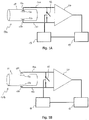
- Fig. 1a a simplified representation of a measuring device according to the present invention with galvanic signal extraction is shown.
- the measuring device 10a has two electrodes 12a, 12b which are in contact with the medium flowing through a pipe 11. Not shown is a magnet that generates a magnetic field (directed into the plane of the drawing). When the medium is flowing, this results in charge separation and the accumulation of positive particles 13a or negative particles 13b on the surfaces of the electrodes 12a, 12b.
- the electrodes 12a, 12b are connected to a switch 16 and a differential amplifier 20 via leads 14a, 14b.
- the switch 16 is connected in parallel to the inputs of the differential amplifier 20.
- the differential amplifier advantageously has a very low temperature dependency and a low offset drift.
- the switch 16 is switched by a control unit 18, the control unit 18 having a timer (not shown) and also controlling an evaluation unit 19.
- the evaluation unit 19 has an analog / digital converter (not shown) and a memory unit.
- Figure 1b shows an exemplary embodiment according to the invention of a measuring device 10b with capacitive signal decoupling.
- the electrodes 12 a, 12 b are therefore arranged outside the tube 11.
- the interconnection of the other elements corresponds to the interconnection of the elements in the measuring device 10a with galvanic signal decoupling.
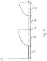
- Fig. 2 the diagram (sketched here only in greatly simplified form) of a voltage profile at the electrodes of a measuring device according to the invention is shown.
- the switch is closed, so that the electrodes and the inputs of the differential amplifier are short-circuited.
- the switch is open for a second period of time 22.
- a first voltage is applied to the electrodes. This first voltage can be measured as a zero point signal and used to calculate a corrected signal.
- the second period 22 there is a settling, the course of which depends, among other things, on the capacitance of the measuring circuit. Typically, there is an increase in voltage, the voltage increase gradually flattening out.
- a measurement of the useful signal takes place during a third, very short period of time 23, which is shown as the point in time in the diagram. For example, the measurement could take place over a period of 1 ⁇ s.
- the switch is closed again for an initial period and a new cycle begins.
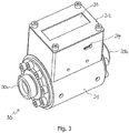
- Fig. 3 shows a perspective view of a measuring device 10 according to the invention.
- the measuring device 10 has openings 30a, 30b for the entry and exit of the medium.
- the measuring device 10 also has a metallic, cylindrical casing 31.
- the casing 31 has as few cutouts and openings as possible in order to suppress interference signals as far as possible.
- a housing 32 for the evaluation unit and the control unit is placed on the casing 31.
- the evaluation unit and the control unit can be implemented on the microcontroller, for example.
- the housing 32 has an opening for a USB socket 34 so that a microcontroller of the measuring device 10 can be connected to a computer.
- the measuring device also has a display 33 on which the current flow rate and the total volume of the medium that has flowed through can be read.
- the measuring device shown has no connection for an external power supply, but is supplied via an integrated battery. In this way, interference caused by fluctuations in an external power supply can be prevented.
- Figure 4a shows a side view of the in Fig. 3 shown measuring device.
- Figure 4b shows a cross section through the measuring device from Figure 4a and Fig. 3 .
- the cross section shows magnets 40a, 40b which are arranged on opposite sides of a passage 45.
- the magnets 40a, 40b are held in their position by brackets 41a, 41b fastened to the housing with screws 42.
- brackets 41a, 41b fastened to the housing with screws 42.
- the openings 30a, 30b have larger diameters than the passage 45.
- an increased flow rate is achieved in the passage 45.
- the leadthrough has the same or a larger diameter than the openings.
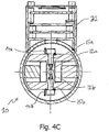
- Figure 4C shows a cross-sectional view through the plane in which the electrodes 12a, 12b are arranged.
- the electrodes are attached to base bodies 15a, 15b.
- the base bodies 15a, 15b are accessible from the outside so that the electrodes 12a, 12b can be exchanged with the base bodies 15a, 15b if necessary.
- the microcontroller on which the control unit and the evaluation unit are located is not shown.
- the microcontroller is intended to be arranged in the housing 32.
- the switch 16 and an amplifier 20 are also located in the housing 32.
- the switch 16 is arranged directly on the electrodes 12a, 12b in order to be able to achieve the lowest possible short-circuit resistance.
- the leads 14a, 14b from the electrodes 12a, 12b to the switch 16 and amplifier 20 are thus different according to this exemplary embodiment long.
- the feed lines are designed symmetrically.
- the leads 14a, 14b are in Figure 4C shown only in abbreviated form. Reinforced wires or litz wires are advantageously used for the supply lines, so that a low short-circuit resistance is achieved.
Landscapes
- Physics & Mathematics (AREA)
- Electromagnetism (AREA)
- Fluid Mechanics (AREA)
- General Physics & Mathematics (AREA)
- Measuring Volume Flow (AREA)
Applications Claiming Priority (1)
| Application Number | Priority Date | Filing Date | Title |
|---|---|---|---|
| PCT/EP2012/057939 WO2013164011A1 (de) | 2012-04-30 | 2012-04-30 | MESSVORRICHTUNG UND - VERFAHREN ZUR MESSUNG DER FLIEßGESCHWINDIGKEIT EINES MEDIUMS |
Publications (2)
| Publication Number | Publication Date |
|---|---|
| EP2844959A1 EP2844959A1 (de) | 2015-03-11 |
| EP2844959B1 true EP2844959B1 (de) | 2021-03-31 |
Family
ID=48227295
Family Applications (1)
| Application Number | Title | Priority Date | Filing Date |
|---|---|---|---|
| EP12722690.0A Active EP2844959B1 (de) | 2012-04-30 | 2012-04-30 | MESSVORRICHTUNG UND - VERFAHREN ZUR MESSUNG DER FLIEßGESCHWINDIGKEIT EINES MEDIUMS |
Country Status (5)
| Country | Link |
|---|---|
| EP (1) | EP2844959B1 (enExample) |
| CN (2) | CN104428634A (enExample) |
| BR (2) | BR112014027144A2 (enExample) |
| IN (2) | IN2014MN02432A (enExample) |
| WO (2) | WO2013164011A1 (enExample) |
Cited By (1)
| Publication number | Priority date | Publication date | Assignee | Title |
|---|---|---|---|---|
| DE102024115520A1 (de) * | 2024-06-04 | 2025-12-04 | Endress+Hauser Conducta Gmbh+Co. Kg | Sensor mit verbesserten elektrischen Eigenschaften |
Families Citing this family (3)
| Publication number | Priority date | Publication date | Assignee | Title |
|---|---|---|---|---|
| DE102013105832B4 (de) * | 2013-06-06 | 2015-03-12 | Zylum Beteiligungsgesellschaft Mbh & Co. Patente Ii Kg | Vorrichtung und Verfahren zur magnetisch-induktiven Durchflussmessung |
| EP3867605A1 (en) * | 2018-10-18 | 2021-08-25 | EICON GmbH | Magnetic flow meter |
| CN116223841A (zh) * | 2023-02-03 | 2023-06-06 | 深圳职业技术学院 | 液体流速测量装置及测量方法 |
Family Cites Families (5)
| Publication number | Priority date | Publication date | Assignee | Title |
|---|---|---|---|---|
| DE2557328C2 (de) * | 1975-12-19 | 1982-06-16 | Fischer & Porter GmbH, 3400 Göttingen | Induktiver Durchflußmesser mit getakteter Gleichstromerregung |
| US5426984A (en) * | 1993-09-02 | 1995-06-27 | Rosemount Inc. | Magnetic flowmeter with empty pipe detector |
| JP3602636B2 (ja) * | 1996-02-26 | 2004-12-15 | 愛知時計電機株式会社 | 電磁流量計 |
| US6463807B1 (en) * | 2000-11-02 | 2002-10-15 | Murray F. Feller | Magnetic flow sensor and method |
| US6722207B1 (en) * | 2002-03-19 | 2004-04-20 | Murray F. Feller | Electro-magnetic flow transducer with insulating scroll |
-
2012
- 2012-04-30 CN CN201280074048.6A patent/CN104428634A/zh active Pending
- 2012-04-30 IN IN2432MUN2014 patent/IN2014MN02432A/en unknown
- 2012-04-30 WO PCT/EP2012/057939 patent/WO2013164011A1/de not_active Ceased
- 2012-04-30 BR BR112014027144A patent/BR112014027144A2/pt not_active IP Right Cessation
- 2012-04-30 EP EP12722690.0A patent/EP2844959B1/de active Active
-
2013
- 2013-04-30 CN CN201380032040.8A patent/CN104395702A/zh active Pending
- 2013-04-30 IN IN2431MUN2014 patent/IN2014MN02431A/en unknown
- 2013-04-30 WO PCT/EP2013/058962 patent/WO2013164329A1/de not_active Ceased
- 2013-04-30 BR BR112014027192A patent/BR112014027192A2/pt not_active IP Right Cessation
Non-Patent Citations (1)
| Title |
|---|
| None * |
Cited By (1)
| Publication number | Priority date | Publication date | Assignee | Title |
|---|---|---|---|---|
| DE102024115520A1 (de) * | 2024-06-04 | 2025-12-04 | Endress+Hauser Conducta Gmbh+Co. Kg | Sensor mit verbesserten elektrischen Eigenschaften |
Also Published As
| Publication number | Publication date |
|---|---|
| CN104428634A (zh) | 2015-03-18 |
| WO2013164329A1 (de) | 2013-11-07 |
| BR112014027144A2 (pt) | 2017-06-27 |
| IN2014MN02432A (enExample) | 2015-08-14 |
| WO2013164011A1 (de) | 2013-11-07 |
| EP2844959A1 (de) | 2015-03-11 |
| CN104395702A (zh) | 2015-03-04 |
| BR112014027192A2 (pt) | 2017-06-27 |
| IN2014MN02431A (enExample) | 2015-08-21 |
Similar Documents
| Publication | Publication Date | Title |
|---|---|---|
| EP2567223B1 (de) | Vorrichtung zur messung der elektrischen leitfähigkeit eines flüssigen mediums | |
| EP1792144B1 (de) | Verfahren zum überprüfen eines magnetisch-induktiven durch flussmessers | |
| DE102013105832B4 (de) | Vorrichtung und Verfahren zur magnetisch-induktiven Durchflussmessung | |
| DE102004057680A1 (de) | Verfahren zur Funktionsüberwachung eines Magnetisch Induktiven Durchflussmessaufnehmers | |
| EP3268698B1 (de) | Magnetisch-induktives durchflussmessgerät mit verringerter stromaufnahme | |
| DE102014007426B4 (de) | Magnetisch-induktives Durchflussmessgerät und Verfahren zum Betreiben eines magnetisch-induktiven Durchflussmessgeräts | |
| EP2844959B1 (de) | MESSVORRICHTUNG UND - VERFAHREN ZUR MESSUNG DER FLIEßGESCHWINDIGKEIT EINES MEDIUMS | |
| DE102012002013A1 (de) | Prüfung einer Messgerätanordnung, entsprechende Messgerätanordnung und Prüfanordnung | |
| DE10356008B4 (de) | Verfahren zum Betreiben eines Meßgeräts | |
| DE10118002A1 (de) | Magnetisch-induktives Durchflußmeßverfahren und magnetisch-induktives Durchflußmeßgerät | |
| EP1460394A2 (de) | Method of regulating the coil current of electromagnetic flow sensors | |
| EP1431716A1 (de) | Magnetisch induktiver Durchflussmesser | |
| DE102013013991A1 (de) | Magnetisch-induktives Durchflussmessgerät | |
| EP1541973B1 (de) | Magnetisch-induktives Durchflussmessgerät und Messverfahren für ein magnetisch-induktives Durchflussmessgerät | |
| EP2844960A1 (de) | Messvorrichtung zur messung der fliessgeschwindigkeit eines mediums | |
| EP2992337B1 (de) | Verfahren und vorrichtung zur überwachung und strommessung an einer magnetisch vorgespannten drossel | |
| DE102021131693A1 (de) | Magnetisch-induktive Durchflussmessvorrichtung | |
| WO2010108805A2 (de) | Magnetisch-induktive durchflussmesseinrichtung und verfahren zum betreiben derselben | |
| DE102011008295A1 (de) | Verfahren zur Durchflussmessung | |
| EP1273891A1 (de) | Verfahren zum Betrieb eines magnetischinduktiven Durchflussmessers | |
| DE102014105837A1 (de) | Vorrichtung zum Messen des Durchflusses eines Fluids durch ein Messrohr | |
| WO2025252776A1 (de) | MEßROHR-MODUL, MODUL-SYSTEM SOWIE DAMIT GEBILDETES MEßGERÄT BZW. DAMIT GEBILDETE PRÜFANORDNUNG | |
| WO2026041288A1 (de) | Magnetisch-induktives durchflussmessgerät und verfahren zum überprüfen eines kurzschlusses | |
| DE102016202159A1 (de) | Verfahren und Vorrichtung zur Bestimmung einer elektrischen Spannung über einer durch Pulsweitenmodulation angesteuerten Last | |
| DE10350000A1 (de) | Magnetfeldtranisitor (MFT) |
Legal Events
| Date | Code | Title | Description |
|---|---|---|---|
| PUAI | Public reference made under article 153(3) epc to a published international application that has entered the european phase |
Free format text: ORIGINAL CODE: 0009012 |
|
| 17P | Request for examination filed |
Effective date: 20141121 |
|
| AK | Designated contracting states |
Kind code of ref document: A1 Designated state(s): AL AT BE BG CH CY CZ DE DK EE ES FI FR GB GR HR HU IE IS IT LI LT LU LV MC MK MT NL NO PL PT RO RS SE SI SK SM TR |
|
| AX | Request for extension of the european patent |
Extension state: BA ME |
|
| DAX | Request for extension of the european patent (deleted) | ||
| STAA | Information on the status of an ep patent application or granted ep patent |
Free format text: STATUS: EXAMINATION IS IN PROGRESS |
|
| 17Q | First examination report despatched |
Effective date: 20200131 |
|
| GRAP | Despatch of communication of intention to grant a patent |
Free format text: ORIGINAL CODE: EPIDOSNIGR1 |
|
| STAA | Information on the status of an ep patent application or granted ep patent |
Free format text: STATUS: GRANT OF PATENT IS INTENDED |
|
| RIC1 | Information provided on ipc code assigned before grant |
Ipc: G01F 1/58 20060101ALI20200717BHEP Ipc: G01F 1/60 20060101AFI20200717BHEP |
|
| INTG | Intention to grant announced |
Effective date: 20200821 |
|
| GRAS | Grant fee paid |
Free format text: ORIGINAL CODE: EPIDOSNIGR3 |
|
| RAP1 | Party data changed (applicant data changed or rights of an application transferred) |
Owner name: ZYLUM BETEILIGUNGSGESELLSCHAFT MBH & CO. PATENTE II KG |
|
| RIN1 | Information on inventor provided before grant (corrected) |
Inventor name: WOLFF, MARCUS Inventor name: BRUHNS, HENRY |
|
| GRAA | (expected) grant |
Free format text: ORIGINAL CODE: 0009210 |
|
| STAA | Information on the status of an ep patent application or granted ep patent |
Free format text: STATUS: THE PATENT HAS BEEN GRANTED |
|
| RAP1 | Party data changed (applicant data changed or rights of an application transferred) |
Owner name: EICON GMBH |
|
| AK | Designated contracting states |
Kind code of ref document: B1 Designated state(s): AL AT BE BG CH CY CZ DE DK EE ES FI FR GB GR HR HU IE IS IT LI LT LU LV MC MK MT NL NO PL PT RO RS SE SI SK SM TR |
|
| REG | Reference to a national code |
Ref country code: GB Ref legal event code: FG4D Free format text: NOT ENGLISH Ref country code: CH Ref legal event code: EP |
|
| REG | Reference to a national code |
Ref country code: AT Ref legal event code: REF Ref document number: 1377432 Country of ref document: AT Kind code of ref document: T Effective date: 20210415 |
|
| REG | Reference to a national code |
Ref country code: DE Ref legal event code: R096 Ref document number: 502012016698 Country of ref document: DE |
|
| REG | Reference to a national code |
Ref country code: IE Ref legal event code: FG4D Free format text: LANGUAGE OF EP DOCUMENT: GERMAN |
|
| REG | Reference to a national code |
Ref country code: LT Ref legal event code: MG9D |
|
| PG25 | Lapsed in a contracting state [announced via postgrant information from national office to epo] |
Ref country code: HR Free format text: LAPSE BECAUSE OF FAILURE TO SUBMIT A TRANSLATION OF THE DESCRIPTION OR TO PAY THE FEE WITHIN THE PRESCRIBED TIME-LIMIT Effective date: 20210331 Ref country code: FI Free format text: LAPSE BECAUSE OF FAILURE TO SUBMIT A TRANSLATION OF THE DESCRIPTION OR TO PAY THE FEE WITHIN THE PRESCRIBED TIME-LIMIT Effective date: 20210331 Ref country code: NO Free format text: LAPSE BECAUSE OF FAILURE TO SUBMIT A TRANSLATION OF THE DESCRIPTION OR TO PAY THE FEE WITHIN THE PRESCRIBED TIME-LIMIT Effective date: 20210630 Ref country code: BG Free format text: LAPSE BECAUSE OF FAILURE TO SUBMIT A TRANSLATION OF THE DESCRIPTION OR TO PAY THE FEE WITHIN THE PRESCRIBED TIME-LIMIT Effective date: 20210630 |
|
| PG25 | Lapsed in a contracting state [announced via postgrant information from national office to epo] |
Ref country code: SE Free format text: LAPSE BECAUSE OF FAILURE TO SUBMIT A TRANSLATION OF THE DESCRIPTION OR TO PAY THE FEE WITHIN THE PRESCRIBED TIME-LIMIT Effective date: 20210331 Ref country code: RS Free format text: LAPSE BECAUSE OF FAILURE TO SUBMIT A TRANSLATION OF THE DESCRIPTION OR TO PAY THE FEE WITHIN THE PRESCRIBED TIME-LIMIT Effective date: 20210331 Ref country code: LV Free format text: LAPSE BECAUSE OF FAILURE TO SUBMIT A TRANSLATION OF THE DESCRIPTION OR TO PAY THE FEE WITHIN THE PRESCRIBED TIME-LIMIT Effective date: 20210331 |
|
| REG | Reference to a national code |
Ref country code: NL Ref legal event code: MP Effective date: 20210331 |
|
| PG25 | Lapsed in a contracting state [announced via postgrant information from national office to epo] |
Ref country code: NL Free format text: LAPSE BECAUSE OF FAILURE TO SUBMIT A TRANSLATION OF THE DESCRIPTION OR TO PAY THE FEE WITHIN THE PRESCRIBED TIME-LIMIT Effective date: 20210331 Ref country code: LT Free format text: LAPSE BECAUSE OF FAILURE TO SUBMIT A TRANSLATION OF THE DESCRIPTION OR TO PAY THE FEE WITHIN THE PRESCRIBED TIME-LIMIT Effective date: 20210331 Ref country code: EE Free format text: LAPSE BECAUSE OF FAILURE TO SUBMIT A TRANSLATION OF THE DESCRIPTION OR TO PAY THE FEE WITHIN THE PRESCRIBED TIME-LIMIT Effective date: 20210331 Ref country code: CZ Free format text: LAPSE BECAUSE OF FAILURE TO SUBMIT A TRANSLATION OF THE DESCRIPTION OR TO PAY THE FEE WITHIN THE PRESCRIBED TIME-LIMIT Effective date: 20210331 Ref country code: SM Free format text: LAPSE BECAUSE OF FAILURE TO SUBMIT A TRANSLATION OF THE DESCRIPTION OR TO PAY THE FEE WITHIN THE PRESCRIBED TIME-LIMIT Effective date: 20210331 |
|
| PG25 | Lapsed in a contracting state [announced via postgrant information from national office to epo] |
Ref country code: IS Free format text: LAPSE BECAUSE OF FAILURE TO SUBMIT A TRANSLATION OF THE DESCRIPTION OR TO PAY THE FEE WITHIN THE PRESCRIBED TIME-LIMIT Effective date: 20210731 Ref country code: RO Free format text: LAPSE BECAUSE OF FAILURE TO SUBMIT A TRANSLATION OF THE DESCRIPTION OR TO PAY THE FEE WITHIN THE PRESCRIBED TIME-LIMIT Effective date: 20210331 Ref country code: SK Free format text: LAPSE BECAUSE OF FAILURE TO SUBMIT A TRANSLATION OF THE DESCRIPTION OR TO PAY THE FEE WITHIN THE PRESCRIBED TIME-LIMIT Effective date: 20210331 Ref country code: PT Free format text: LAPSE BECAUSE OF FAILURE TO SUBMIT A TRANSLATION OF THE DESCRIPTION OR TO PAY THE FEE WITHIN THE PRESCRIBED TIME-LIMIT Effective date: 20210802 Ref country code: PL Free format text: LAPSE BECAUSE OF FAILURE TO SUBMIT A TRANSLATION OF THE DESCRIPTION OR TO PAY THE FEE WITHIN THE PRESCRIBED TIME-LIMIT Effective date: 20210331 Ref country code: ES Free format text: LAPSE BECAUSE OF FAILURE TO SUBMIT A TRANSLATION OF THE DESCRIPTION OR TO PAY THE FEE WITHIN THE PRESCRIBED TIME-LIMIT Effective date: 20210331 |
|
| PG25 | Lapsed in a contracting state [announced via postgrant information from national office to epo] |
Ref country code: LU Free format text: LAPSE BECAUSE OF NON-PAYMENT OF DUE FEES Effective date: 20210430 |
|
| REG | Reference to a national code |
Ref country code: DE Ref legal event code: R097 Ref document number: 502012016698 Country of ref document: DE |
|
| REG | Reference to a national code |
Ref country code: BE Ref legal event code: MM Effective date: 20210430 |
|
| PG25 | Lapsed in a contracting state [announced via postgrant information from national office to epo] |
Ref country code: DK Free format text: LAPSE BECAUSE OF FAILURE TO SUBMIT A TRANSLATION OF THE DESCRIPTION OR TO PAY THE FEE WITHIN THE PRESCRIBED TIME-LIMIT Effective date: 20210331 Ref country code: MC Free format text: LAPSE BECAUSE OF FAILURE TO SUBMIT A TRANSLATION OF THE DESCRIPTION OR TO PAY THE FEE WITHIN THE PRESCRIBED TIME-LIMIT Effective date: 20210331 Ref country code: AL Free format text: LAPSE BECAUSE OF FAILURE TO SUBMIT A TRANSLATION OF THE DESCRIPTION OR TO PAY THE FEE WITHIN THE PRESCRIBED TIME-LIMIT Effective date: 20210331 |
|
| PLBE | No opposition filed within time limit |
Free format text: ORIGINAL CODE: 0009261 |
|
| STAA | Information on the status of an ep patent application or granted ep patent |
Free format text: STATUS: NO OPPOSITION FILED WITHIN TIME LIMIT |
|
| GBPC | Gb: european patent ceased through non-payment of renewal fee |
Effective date: 20210630 |
|
| 26N | No opposition filed |
Effective date: 20220104 |
|
| PG25 | Lapsed in a contracting state [announced via postgrant information from national office to epo] |
Ref country code: IE Free format text: LAPSE BECAUSE OF NON-PAYMENT OF DUE FEES Effective date: 20210430 Ref country code: GB Free format text: LAPSE BECAUSE OF NON-PAYMENT OF DUE FEES Effective date: 20210630 |
|
| PG25 | Lapsed in a contracting state [announced via postgrant information from national office to epo] |
Ref country code: IS Free format text: LAPSE BECAUSE OF FAILURE TO SUBMIT A TRANSLATION OF THE DESCRIPTION OR TO PAY THE FEE WITHIN THE PRESCRIBED TIME-LIMIT Effective date: 20210731 |
|
| REG | Reference to a national code |
Ref country code: AT Ref legal event code: MM01 Ref document number: 1377432 Country of ref document: AT Kind code of ref document: T Effective date: 20210430 |
|
| PG25 | Lapsed in a contracting state [announced via postgrant information from national office to epo] |
Ref country code: IT Free format text: LAPSE BECAUSE OF FAILURE TO SUBMIT A TRANSLATION OF THE DESCRIPTION OR TO PAY THE FEE WITHIN THE PRESCRIBED TIME-LIMIT Effective date: 20210331 Ref country code: BE Free format text: LAPSE BECAUSE OF NON-PAYMENT OF DUE FEES Effective date: 20210430 |
|
| PG25 | Lapsed in a contracting state [announced via postgrant information from national office to epo] |
Ref country code: AT Free format text: LAPSE BECAUSE OF NON-PAYMENT OF DUE FEES Effective date: 20210430 |
|
| PG25 | Lapsed in a contracting state [announced via postgrant information from national office to epo] |
Ref country code: HU Free format text: LAPSE BECAUSE OF FAILURE TO SUBMIT A TRANSLATION OF THE DESCRIPTION OR TO PAY THE FEE WITHIN THE PRESCRIBED TIME-LIMIT; INVALID AB INITIO Effective date: 20120430 Ref country code: CY Free format text: LAPSE BECAUSE OF FAILURE TO SUBMIT A TRANSLATION OF THE DESCRIPTION OR TO PAY THE FEE WITHIN THE PRESCRIBED TIME-LIMIT Effective date: 20210331 |
|
| P01 | Opt-out of the competence of the unified patent court (upc) registered |
Effective date: 20230523 |
|
| PG25 | Lapsed in a contracting state [announced via postgrant information from national office to epo] |
Ref country code: GR Free format text: LAPSE BECAUSE OF FAILURE TO SUBMIT A TRANSLATION OF THE DESCRIPTION OR TO PAY THE FEE WITHIN THE PRESCRIBED TIME-LIMIT Effective date: 20210331 |
|
| PG25 | Lapsed in a contracting state [announced via postgrant information from national office to epo] |
Ref country code: MK Free format text: LAPSE BECAUSE OF FAILURE TO SUBMIT A TRANSLATION OF THE DESCRIPTION OR TO PAY THE FEE WITHIN THE PRESCRIBED TIME-LIMIT Effective date: 20210331 |
|
| PGFP | Annual fee paid to national office [announced via postgrant information from national office to epo] |
Ref country code: DE Payment date: 20240419 Year of fee payment: 13 |
|
| PGFP | Annual fee paid to national office [announced via postgrant information from national office to epo] |
Ref country code: CH Payment date: 20240501 Year of fee payment: 13 |
|
| PG25 | Lapsed in a contracting state [announced via postgrant information from national office to epo] |
Ref country code: MT Free format text: LAPSE BECAUSE OF FAILURE TO SUBMIT A TRANSLATION OF THE DESCRIPTION OR TO PAY THE FEE WITHIN THE PRESCRIBED TIME-LIMIT Effective date: 20210331 |
|
| PGFP | Annual fee paid to national office [announced via postgrant information from national office to epo] |
Ref country code: FR Payment date: 20250429 Year of fee payment: 14 |
|
| REG | Reference to a national code |
Ref country code: DE Ref legal event code: R119 Ref document number: 502012016698 Country of ref document: DE |
|
| REG | Reference to a national code |
Ref country code: CH Ref legal event code: H13 Free format text: ST27 STATUS EVENT CODE: U-0-0-H10-H13 (AS PROVIDED BY THE NATIONAL OFFICE) Effective date: 20251125 |
|
| PG25 | Lapsed in a contracting state [announced via postgrant information from national office to epo] |
Ref country code: TR Free format text: LAPSE BECAUSE OF FAILURE TO SUBMIT A TRANSLATION OF THE DESCRIPTION OR TO PAY THE FEE WITHIN THE PRESCRIBED TIME-LIMIT Effective date: 20210331 |
|
| PG25 | Lapsed in a contracting state [announced via postgrant information from national office to epo] |
Ref country code: DE Free format text: LAPSE BECAUSE OF NON-PAYMENT OF DUE FEES Effective date: 20251104 |
|
| PG25 | Lapsed in a contracting state [announced via postgrant information from national office to epo] |
Ref country code: CH Free format text: LAPSE BECAUSE OF NON-PAYMENT OF DUE FEES Effective date: 20250430 |