EP2842903A1 - Boom extension and contraction mechanism for crane apparatus - Google Patents
Boom extension and contraction mechanism for crane apparatus Download PDFInfo
- Publication number
- EP2842903A1 EP2842903A1 EP14181773.4A EP14181773A EP2842903A1 EP 2842903 A1 EP2842903 A1 EP 2842903A1 EP 14181773 A EP14181773 A EP 14181773A EP 2842903 A1 EP2842903 A1 EP 2842903A1
- Authority
- EP
- European Patent Office
- Prior art keywords
- boom
- cylinder
- reel
- members
- boom member
- Prior art date
- Legal status (The legal status is an assumption and is not a legal conclusion. Google has not performed a legal analysis and makes no representation as to the accuracy of the status listed.)
- Granted
Links
Images




Classifications
-
- B—PERFORMING OPERATIONS; TRANSPORTING
- B66—HOISTING; LIFTING; HAULING
- B66C—CRANES; LOAD-ENGAGING ELEMENTS OR DEVICES FOR CRANES, CAPSTANS, WINCHES, OR TACKLES
- B66C23/00—Cranes comprising essentially a beam, boom, or triangular structure acting as a cantilever and mounted for translatory of swinging movements in vertical or horizontal planes or a combination of such movements, e.g. jib-cranes, derricks, tower cranes
- B66C23/62—Constructional features or details
- B66C23/64—Jibs
- B66C23/70—Jibs constructed of sections adapted to be assembled to form jibs or various lengths
- B66C23/701—Jibs constructed of sections adapted to be assembled to form jibs or various lengths telescopic
- B66C23/706—Jibs constructed of sections adapted to be assembled to form jibs or various lengths telescopic telescoped by other means
-
- B—PERFORMING OPERATIONS; TRANSPORTING
- B66—HOISTING; LIFTING; HAULING
- B66C—CRANES; LOAD-ENGAGING ELEMENTS OR DEVICES FOR CRANES, CAPSTANS, WINCHES, OR TACKLES
- B66C23/00—Cranes comprising essentially a beam, boom, or triangular structure acting as a cantilever and mounted for translatory of swinging movements in vertical or horizontal planes or a combination of such movements, e.g. jib-cranes, derricks, tower cranes
- B66C23/62—Constructional features or details
- B66C23/64—Jibs
- B66C23/70—Jibs constructed of sections adapted to be assembled to form jibs or various lengths
- B66C23/701—Jibs constructed of sections adapted to be assembled to form jibs or various lengths telescopic
- B66C23/705—Jibs constructed of sections adapted to be assembled to form jibs or various lengths telescopic telescoped by hydraulic jacks
-
- B—PERFORMING OPERATIONS; TRANSPORTING
- B66—HOISTING; LIFTING; HAULING
- B66C—CRANES; LOAD-ENGAGING ELEMENTS OR DEVICES FOR CRANES, CAPSTANS, WINCHES, OR TACKLES
- B66C23/00—Cranes comprising essentially a beam, boom, or triangular structure acting as a cantilever and mounted for translatory of swinging movements in vertical or horizontal planes or a combination of such movements, e.g. jib-cranes, derricks, tower cranes
- B66C23/62—Constructional features or details
- B66C23/64—Jibs
- B66C23/70—Jibs constructed of sections adapted to be assembled to form jibs or various lengths
- B66C23/701—Jibs constructed of sections adapted to be assembled to form jibs or various lengths telescopic
- B66C23/708—Jibs constructed of sections adapted to be assembled to form jibs or various lengths telescopic locking devices for telescopic jibs
-
- B—PERFORMING OPERATIONS; TRANSPORTING
- B66—HOISTING; LIFTING; HAULING
- B66C—CRANES; LOAD-ENGAGING ELEMENTS OR DEVICES FOR CRANES, CAPSTANS, WINCHES, OR TACKLES
- B66C2700/00—Cranes
- B66C2700/03—Cranes with arms or jibs; Multiple cranes
Definitions
- the present invention relates to a boom extension and contraction mechanism for a crane apparatus including a boom that is extended and contracted by one hydraulic cylinder.
- this sort of boom extension and contraction mechanism that includes a boom with a plurality of boom members and one telescopic cylinder; the telescopic cylinder allows the boom to extend and contract by shifting next boom members in front of respective ones with respect to the boom members other than a top boom member; and one of a cylinder rod and a cylinder tube of the telescopic cylinder is connected to the bottom boom member (see, for example, Patent Literature 1).
- the boom extension and contraction mechanism includes: a cylinder-to-boom connection mechanism that can connect and disconnect between the other of the cylinder rod and the cylinder tube, and the boom members other than the bottom boom member; and a boom member connection mechanism that can connect and disconnect between the boom members next to one other.
- the cylinder-to-boom connection mechanism and the boom member connection mechanism of the boom extension and contraction mechanism are driven by respective hydraulic double acting cylinders. Therefore, two hydraulic hoses to supply and discharge hydraulic oil are required for each of the hydraulic double acting cylinders that drive the cylinder-to-boom connection mechanism and the boom member connection mechanism, respectively.
- the double acting cylinders are provided in the other of the cylinder rod and the cylinder tube of the telescopic cylinder, and therefore change in their positions according to the telescopic motion of the telescopic cylinder.
- the hydraulic hose connected to each of the double acting cylinders is wound around a hose reel provided on a swivel base to which the base end of the boom is connected, and therefore is reeled out and off according to the tele-scopic motion of the boom.
- the hydraulic hose connected to each of the double acting cylinders is a twin hose having a pair of hydraulic oil passages integrally formed with each of the double acting cylinders.
- the boom extension and contraction mechanism further includes a boom detection sensor that detects which of the boom members is connected to the telescopic cylinder. Therefore, a communication cable is required to transmit a detection signal from the boom detection sensor.
- the boom detection sensor is provided in the other of the cylinder rod and the cylinder tube of the telescopic cylinder, and therefore changes in its position with respect to the base end of the boom according to the telescopic motion of the telescopic cylinder. Therefore, the communication cable wound around a cord reel provided on the swivel base like the hose reel is reeled out and off according to the telescopic motion of the boom.
- This boom extension and contraction mechanism needs two hose reels around which the pair of hydraulic hoses is wound, and also needs a cord reel around which the communication cable is wound. As a result, the number of parts is increased and the structure of the based end of the boom is complicated.
- the twin hose is normally wound around the hose reel outward in the radial direction in order to make the fleet angle a predetermined angle or lower in terms of the relationship with the sheave that guides the twin hose. Therefore, the hose reel around which the twin hose is wound is increased in size in the radial direction. Consequently, when mounted on the swivel base, the hose reel substantially protrudes backward from the swivel base. As a result, the counter weight mounted on the back of the swivel base protrudes further to increase the angle of traverse, and therefore the working efficiency may be deteriorated.
- a boom extension and contraction mechanism which includes the cylinder-to-boom connection mechanism and the boom member connection mechanism driven by hydraulic single acting cylinders, respectively, and also includes a hydraulic oil passage to supply hydraulic oil to each of the single acting cylinders, which is provided in each of the cylinder tube and the cylinder rod of the telescopic cylinder.
- the hydraulic oil passage to supply hydraulic oil to each of the single acting cylinders extends and contracts according to the telescopic motion of the telescopic cylinder. Therefore, merely the inlet/outlet of the hydraulic oil passage provided in the telescopic cylinder is connected to each of the single acting cylinders, so that a hose reel is not needed.
- Patent literature 1 Japanese Patent Application Laid-Open No. 2002-332194
- the boom extension and contraction mechanism includes: a boom including a plurality of boom members, the boom extending and contracting by shifting next boom members in front of respective ones with respect to the boom members other than a top boom member; a base configured to support a base end of a bottom boom member; a telescopic cylinder including a cylinder rod and a cylinder tube, one of the cylinder rod and the cylinder tube being connected to the bottom boom member to extend and contract the boom; a cylinder-to-boom connection mechanism configured to be able to connect and disconnect between the other of the cylinder rod and the cylinder tube and the boom members other than the bottom boom member; a boom member connection mechanism configured to be able to connect between the boom members next to one another and release the boom members from being connected to one another; a cylinder-to-boom connection switching cylinder configured to allow the cylinder-to-boom connection mechanism to perform one of a connecting operation and a disconnecting operation between the telescopic cylinder and
- the size of the hose reel is increased in the direction of the rotating axis while reducing the size of the hose reel in the radial direction, so that it is possible to reduce the dimension for which the hose reel protrudes from the back of the swivel base.
- the hose reel and the cord reel are arranged on the swivel base in the direction in which the boom extends and contracts, and therefore it is possible to place the hydraulic hose and the cable near one another and extend them to the other of the cylinder rod and the cylinder tube.
- the present invention it is possible to increase the dimension of the hose reel in the direction of the rotating axis while reducing the dimension in the radial direction. Also, it is possible to reduce the dimension for which the hose reel protrudes from the back of the swivel base, and therefore to reduce the angle of traverse in back of the swivel base, with a simple structure. Moreover, it is possible to place the hydraulic hose and the cable near one another and extend them to the other of the cylinder rod and the cylinder tube. Therefore, it is possible to reduce the size of the boom in the width direction.
- Figs. 1 to 8 show an embodiment of the present invention.
- a mobile crane 1 will be described as a crane apparatus having a boom extension and contraction mechanism according to the present invention.
- the mobile crane 1 includes a vehicle 10 that runs on the ground, and a crane apparatus 20 as an operation part.
- the vehicle 10 has wheels 11 and runs by an engine (not shown) as a power source.
- outriggers 12 are provided on the right and left sides of the front part of the vehicle 10 and also on the right and left sides of the rear part of the vehicle 10 to prevent the vehicle 10 from overturning and support the vehicle 10 stably when the crane is working.
- Each outrigger 12 is movable outward in the width direction and also extendable downward by a hydraulic jack cylinder (not shown). The bottom ends of the outriggers 12 contact the ground to support the vehicle 10 on the ground stably.
- the crane apparatus 20 includes a swivel base 21 that is pivotably provided in the center part of the vehicle 10 in the longitudinal direction and is configured to be able to swivel on a horizontal plane; a boom 22 provided to be able to rise and down with respect to the swivel base 21 and to be able to extend and contract; and a cabin 23 provided in the front part of the swivel base 21 to run the vehicle 10 and operate the crane apparatus 20 to work.
- the swivel base 21 is configured to be able to swivel with respect to the vehicle 10 by means of a ball bearing or roller bearing swivel support.
- the swivel base 21 is driven by a hydraulic swivel motor (not shown).
- the boom 22 is constituted by a plurality of boom members 22a, 22b, 22c, 22d, 22e and 22f and formed as a telescopic boom in such a manner that the boom members 22a, 22b, 22c, 22d, and 22e can accommodate the respective next boom members 22b, 22c, 22d, 22e and 22f in front of the boom members 22a, 22b, 22c, 22d, and 22e.
- the boom 22 according to the preset embodiment is constituted by six boom members, the bottom boom member 22a, the second boom member 22b, the third boom member 22c, the fourth boom member 22d, the fifth boom member 22e, and the top boom member 22f, which are arranged in the order from the base end of the boom 22.
- the base end of the bottom boom member 22a is swingably connected to a bracket 21 a of the swivel base 21.
- a hydraulic luffing cylinder 22g is connected between the bottom boom member 22a and the bracket 21 a, and extends and contracts to allow the boom 22 to rise and down.
- a boom extension and contraction mechanism 30 allows the boom 22 to extend and contract.
- the boom extension and contraction mechanism includes: a telescopic cylinder 31 that shifts the boom members 22b, 22c, 22d, 22e and 22f other than the bottom boom member 22a; a cylinder-to-boom connection mechanism that removably connects between the telescopic cylinder 31 and the boom members 22b, 22c, 22d, 22e and 22f other than the bottom boom member 22a; a plurality of boom member connection mechanism 33 that removably connect between the boom members 22a, 22b, 22c, 22d and, 22e and respective next ones, the boom members 22b, 22c, 22d, 22e and 22f in front of the boom members 22a, 22b, 22c, 22d and 22e; and a boom member disconnection mechanism 34 that disconnects between the boom members 22a, 22b, 22c, 22d, and 22e and respective next ones, the boom members 22b, 22c, 22d, 22e and 22f in front of the boom members 22a, 22b, 22c, 22d and 22e; and
- the telescopic cylinder 31 includes a cylinder tube 31 a and a cylinder rod 31 b.
- the front end of the cylinder rod 31 b is connected to the base end of the bottom boom member 22a in the bottom boom member 22a.
- the cylinder tube 31a moves with respect to the cylinder rod 31 b in the direction in which the boom 22 extends and contracts.
- the cylinder-to-boom connection mechanism 32 is provided on the outer periphery of the cylinder tube 31 a the telescopic cylinder 31.
- the cylinder-to-boom connection mechanism 32 includes a pair of cylinder pins 32a that can engage the boom members 22b, 22c, 22d, 22e and 22f other than the bottom boom member 22a; and a cylinder-to-boom connection switching cylinder 32b that releases the pair of cylinder pins 32a from engaging the boom members 22b, 22c, 22d, 22e and 22f other than the bottom boom member 22a.
- a cylinder pin engagement part 32c formed in a concave shape is provided in the base end side of each of the boom members 22b, 22c, 22d, 22e and 22f other than the bottom boom member 22a.
- the cylinder pin 32a can engage each of the cylinder pin engagement part 32c.
- the pair of cylinder pins 32a can move in the radial direction of the cylinder tube 31 a. When being moved outward in the radial direction, the pair of cylinder pins 32a engages the cylinder pin engagement parts 32c. Meanwhile, when being moved inward in the radial direction, the pair of cylinder pins 32 is released from engaging the cylinder pin engagement parts 32c.
- the cylinder-to-boom connection switching cylinder 32b is a spring return type of single acting cylinder that biases the cylinder pins 32a in the direction in which the cylinder pins 32a engage the cylinder pin engagement parts 32c. BY supplying the hydraulic oil, the cylinder-to-boom connection switching cylinder 32b releases the cylinder pins 32a from engaging with the cylinder engagement parts 32c.
- each of the boom member connection mechanisms 33 includes: a boom member connection pin 33a provided in each of the boom members 22b, 22c, 22d, 22e and 22f in the front end side of the boom 22; and a pin engagement hole 22b provided in each of the boom members 22a, 22b, 22c, 22d and 22e in the base end side of the boom 22, which can engage the boom member connection pin 33a.
- the boom member connection pin 33a is biased in the direction in which the front end of the boom member connection pin 33a engages the pin engagement hole 33b of the next boom member 22a, 22b, 22c, 22d, and 22e in the base end side.
- a lever engagement part 33c to engage a disconnection lever 33c of the boom member disconnection mechanism 34 described later is provided on the boom member connection pin 33a.
- the pin engagement holes 33b are provided for the base end sides and front end sides of the boom members 22a, 22b, 22c, 22d and 22e.
- the pin engagement holes 33b are provided in positions to meet the protrusion length of the boom members 22b, 22c, 22d, 22e, and 22f from the respective next boom members 22a, 22b, 22c, 22d, and 22f in front of the boom members 22a, 22b, 22c, 22d, and 22e, in addition to the base end sides and front end side of the boom members 22a, 22b, 22c, 22d and 22e.
- the boom member disconnection mechanism 34 is provided on the outer periphery of the cylinder tube 31 a of the telescopic cylinder 31, and has a disconnection lever 34a that can engage the lever engagement part 33c for any boom member connection pin 33a, and a boom member connection switching cylinder 34b that activates the disconnection lever 34a.
- the disconnection lever 34a can engage the lever engagement part 33c of the boom member connection pin 33a at the position at which the pair of cylinder pins 32a engages the cylinder pin engagement parts 32c. In addition, by driving the boom member connection switching cylinder 34b, the disconnection lever 34a releases the boom member connection pins 33a from connecting between the boom members.
- the boom member connection switching cylinder 34b is a spring return type of single acting cylinder. With the supply of the hydraulic oil, the boom member connection switching cylinder 34b activates the disconnection lever 34a in the direction in which the boom member connection pins 33a are released from connecting between the boom members.
- the boom extension and contraction mechanism 30 further includes a hydraulic oil supply circuit 35 for supplying the cylinder-to-boom connection switching cylinder 32b and the boom member connection switching cylinder 34b with the hydraulic oil discharged from the hydraulic pump 40.
- the hydraulic oil supply circuit 35 includes a hydraulic hose 35a for flowing the hydraulic oil discharged from the hydraulic pump 40 into the cylinder-to-boom connection switching cylinder 32b and the boom member connection switching cylinder 34b; and a flow passage switching valve 35b for switching the flow passage of the hydraulic oil discharged from the hydraulic hose 35a between the cylinder-to-boom connection switching cylinder 32b and the boom member connection switching cylinder 34b.
- the hydraulic hose 35a is made of a flexible material and has a length that can supply the hydraulic oil to the cylinder-to-boom connection switching cylinder 32b and the boom member connection switching cylinder 34b while the telescopic cylinder 31 is maximally extended.
- the hydraulic hose 35a wound around the hose reel 35c is reeled out from the hose reel 35c as the telescopic cylinder 31 is extending, and is reeled off on the hose reel 35c as the telescopic cylinder 31 is contracting.
- the hose reel 35c is mounted on the bracket 21 a and located below the base end of the bottom boom member 22a.
- the hose reel 35c has a dimension in the direction of the rotating axis that allows the hydraulic hose 35a to be wound around the hose reel 35c in a single layer in the direction of the rotating axis and has a dimension in the radial direction that allows the hydraulic hose 35a to be wound around the hose reel 35c in layers outward in the radial direction.
- the hydraulic hose 35a wound around the hose reel 35c is guided by a first sheave 35d and extends to the cylinder-to-boom connection switching cylinder 32b and the boom member connection switching cylinder 34b side.
- the first sheave 35d is rotatably provided on the base end of the bottom boom member 22a located above the hose reel 35c.
- the boom extension and contraction mechanism 30 further includes a plurality of proximity switches 36 that detect which of the boom members 22b, 22c, 22d, 22e, and 22f is connected to the cylinder pins 32a, in order to detect the drive condition of the cylinder-to-boom connection switching cylinder 32b and the boom member connection switching cylinder 34b.
- These proximity switches 36 and a solenoid that drives the flow passage switching valve 35b are connected to a controller provided in, for example, the vehicle 10 via the cable 37.
- the cable 37 is constituted by a plurality of flexible signal lines and has a length that can reach the proximity switches 36 and the flow passage switching valve 35b while telescopic cylinder 31 is maximally extended.
- the cable 37 wound around the cord reel 37a is reeled out from the cord reel 37a as the telescopic cylinder 31 is extending, and is reeled off on the cord reel 37a as the telescopic cylinder 31 is contracting.
- the cord reel 37a is mounted on the bracket 21 a and located below the base end of the bottom boom member 22a and in front of the hose reel 35c.
- the cord reel 37a has a dimension in the direction of the rotating axis that allows the cable 37 to be wound around the cord reel 37a in a single layer in the direction of the rotating axis.
- the cable 37 wound around the cord reel 37a is guided by a roller guide 37b and a second sheave 37c and extends to the proximity switches 36 and the flow channel switching valve 35b side.
- the roller guide 37b is rotatably provided on the bracket 21 a at a position behind and obliquely above the cord reel 37a.
- the second sheave 37c is rotatably provided on the base end of the bottom boom member 22a located above the roller guide 37b on the same axis as the first sheave 35d.
- the fleet angle means angle ⁇ made by line A connecting the center of the sheave in the direction of the rotating axis and the center of the reel in the direction of the rotating axis and line B connecting the center of the sheave in the direction of the rotating axis and the inner surface of a flange in the direction of the rotating axis of the reel.
- the relationship between the positions of the hose reel 35c and the first sheave 35d, the relationship between the positions of the cord reel 37a and the second sheave 37c, and the dimensions of the hose reel 35c and the cord reel 37a in the direction of the rotating axis are determined such that the fleet angle is within two degrees.
- the boom members 22b, 22c, 22d, 22e and 22f accommodated in the boom members 22a, 22b, 22c, 22d and 22e in back of them, respectively, are shifted in the order from the boom member 22f that is located in the front end side.
- the boom members 22b, 22c, 22d, 22e and 22f protruding from the boom members 22a, 22b, 22c, 22d and 22e in back of them, respectively, are shifted in the order from the boom member that is located in the base end side.
- the boom extension and contraction mechanism 30 In order to extend and contract the boom 22, the boom extension and contraction mechanism 30 first supplies the cylinder-to-boom connection switching cylinder 32b with the hydraulic oil to release the cylinder pins 32a from engaging the boom member and then drive the telescopic cylinder 31 (see Fig. 8A ). Next, the boom extension and contraction mechanism 30 shifts the cylinder pins 32a to the position at which the cylinder pins 32a face the cylinder pin engagement parts 32c of the boom member intended to be shifted by driving the telescopic cylinder 31, and stops supplying the hydraulic oil to the cylinder-to-boom connection switching cylinder 32b to release the cylinder pins 32a from disconnecting from the boom member.
- the cylinder pins 32a engage the cylinder pin engagement part 32c for the boom member intended to be shifted (see Fig. 8B ).
- the boom extension and contraction mechanism 30 disconnects between the boom member to be shifted and the next boom member in the base end side by supplying the boom member connection switching cylinder 34b with the hydraulic oil.
- the boom extension and contraction mechanism 30 drives the telescopic cylinder 31 to allow the boom 22 to extend and contract (see Fig. 8C ).
- the boom extension and contraction mechanism 30 stop supplying the boom member connection switching cylinder 34b with the hydraulic oil, and connect the shifted boom member to the next boom member in the base end side.
- the boom extension and contraction mechanism for a crane apparatus includes: a hydraulic hose 35a configured to supply hydraulic oil from the swivel base side 21 to the cylinder-to-boom connection switching cylinder 32b and the boom member connection switching cylinder 34b; a flow passage switching valve 35b configured to switch the flow passage of the hydraulic oil supplied via the hydraulic hose 35a between the cylinder-to-boom connection switching cylinder 32b side and the boom member connection switching cylinder 34b side; a hose reel 35c configured to reel out the hydraulic hose 35a as the telescopic cylinder 31 is extending, and reel off the hydraulic hose 35a as telescopic cylinder 31 is contracting; a cable 37 used to supply power from the swivel base 21 side to the solenoid for driving the flow passage switching valve 35b and to transmit signals from the proximity switches 36 to the swivel base 21 side; and a cord reel 37a configured to reel off the cable 37 as the telescopic cylinder 31 is extending and to
- the hose reel 35c and the cord reel 37a are arranged on the swivel base 21 in the direction in which the boom 2 extends and contracts.
- the boom extension and contraction mechanism according to the present invention is applied to a mobile crane.
- the boom extension and contraction mechanism according to the present invention is applicable to a fixed crane apparatus.
Landscapes
- Engineering & Computer Science (AREA)
- Mechanical Engineering (AREA)
- Jib Cranes (AREA)
Description
- The present invention relates to a boom extension and contraction mechanism for a crane apparatus including a boom that is extended and contracted by one hydraulic cylinder.
- Conventionally, there has been known this sort of boom extension and contraction mechanism that includes a boom with a plurality of boom members and one telescopic cylinder; the telescopic cylinder allows the boom to extend and contract by shifting next boom members in front of respective ones with respect to the boom members other than a top boom member; and one of a cylinder rod and a cylinder tube of the telescopic cylinder is connected to the bottom boom member (see, for example, Patent Literature 1).
- The boom extension and contraction mechanism includes: a cylinder-to-boom connection mechanism that can connect and disconnect between the other of the cylinder rod and the cylinder tube, and the boom members other than the bottom boom member; and a boom member connection mechanism that can connect and disconnect between the boom members next to one other.
- The cylinder-to-boom connection mechanism and the boom member connection mechanism of the boom extension and contraction mechanism are driven by respective hydraulic double acting cylinders. Therefore, two hydraulic hoses to supply and discharge hydraulic oil are required for each of the hydraulic double acting cylinders that drive the cylinder-to-boom connection mechanism and the boom member connection mechanism, respectively. The double acting cylinders are provided in the other of the cylinder rod and the cylinder tube of the telescopic cylinder, and therefore change in their positions according to the telescopic motion of the telescopic cylinder. The hydraulic hose connected to each of the double acting cylinders is wound around a hose reel provided on a swivel base to which the base end of the boom is connected, and therefore is reeled out and off according to the tele-scopic motion of the boom. In addition, the hydraulic hose connected to each of the double acting cylinders is a twin hose having a pair of hydraulic oil passages integrally formed with each of the double acting cylinders.
- The boom extension and contraction mechanism further includes a boom detection sensor that detects which of the boom members is connected to the telescopic cylinder. Therefore, a communication cable is required to transmit a detection signal from the boom detection sensor. The boom detection sensor is provided in the other of the cylinder rod and the cylinder tube of the telescopic cylinder, and therefore changes in its position with respect to the base end of the boom according to the telescopic motion of the telescopic cylinder. Therefore, the communication cable wound around a cord reel provided on the swivel base like the hose reel is reeled out and off according to the telescopic motion of the boom.
- This boom extension and contraction mechanism needs two hose reels around which the pair of hydraulic hoses is wound, and also needs a cord reel around which the communication cable is wound. As a result, the number of parts is increased and the structure of the based end of the boom is complicated.
- Moreover, the twin hose is normally wound around the hose reel outward in the radial direction in order to make the fleet angle a predetermined angle or lower in terms of the relationship with the sheave that guides the twin hose. Therefore, the hose reel around which the twin hose is wound is increased in size in the radial direction. Consequently, when mounted on the swivel base, the hose reel substantially protrudes backward from the swivel base. As a result, the counter weight mounted on the back of the swivel base protrudes further to increase the angle of traverse, and therefore the working efficiency may be deteriorated.
- To solve this problem with an increase in the angle of traverse of the counter weight, a boom extension and contraction mechanism is expected which includes the cylinder-to-boom connection mechanism and the boom member connection mechanism driven by hydraulic single acting cylinders, respectively, and also includes a hydraulic oil passage to supply hydraulic oil to each of the single acting cylinders, which is provided in each of the cylinder tube and the cylinder rod of the telescopic cylinder. With this boom extension and contraction mechanism, the hydraulic oil passage to supply hydraulic oil to each of the single acting cylinders extends and contracts according to the telescopic motion of the telescopic cylinder. Therefore, merely the inlet/outlet of the hydraulic oil passage provided in the telescopic cylinder is connected to each of the single acting cylinders, so that a hose reel is not needed.
- Patent literature 1: Japanese Patent Application Laid-Open No.
2002-332194 - Here, with the boom extension and contraction mechanism without a hose reel, it is possible to reduce the angle of traverse in the back of the swivel base. However, since the hydraulic oil passage is provided in the telescopic cylinder, the structure is complicated, and therefore it is not easy to address a failure that occurs in the telescopic cylinder.
- It is therefore an object of the present invention to provide a simple boom extension and contraction mechanism for a crane apparatus that can reduce the angle of traverse in the back of the swivel base.
- To achieve the above-described object, the boom extension and contraction mechanism according to the present invention includes: a boom including a plurality of boom members, the boom extending and contracting by shifting next boom members in front of respective ones with respect to the boom members other than a top boom member; a base configured to support a base end of a bottom boom member; a telescopic cylinder including a cylinder rod and a cylinder tube, one of the cylinder rod and the cylinder tube being connected to the bottom boom member to extend and contract the boom; a cylinder-to-boom connection mechanism configured to be able to connect and disconnect between the other of the cylinder rod and the cylinder tube and the boom members other than the bottom boom member; a boom member connection mechanism configured to be able to connect between the boom members next to one another and release the boom members from being connected to one another; a cylinder-to-boom connection switching cylinder configured to allow the cylinder-to-boom connection mechanism to perform one of a connecting operation and a disconnecting operation between the telescopic cylinder and a boom member by supplying hydraulic oil, and to allow the cylinder-to-boom connection mechanism to perform the other of the connecting operation and the disconnecting operation between the telescopic cylinder and the boom member by stopping supplying the hydraulic oil; a boom member connection switching cylinder configured to allow the boom member connection mechanism to perform one of a connecting operation and a disconnecting operation between the boom members next to one another by supplying the hydraulic oil, and to allow the boom member connection mechanism to perform the other of the connecting operation and the disconnecting operation between the boom members next to one another by stopping supplying the hydraulic oil; a hydraulic hose configured to supply the hydraulic oil from the base side to the cylinder-to-boom connection switching cylinder and the boom member connection switching cylinder; a flow passage switching mechanism configured to switch a flow passage of the hydraulic oil supplied via the hydraulic hose between the cylinder-to-boom connection switching cylinder side and the boom member connection switching cylinder side; a hose reel configured to reel out the hydraulic hose as the telescopic cylinder is extending, and to reel off the hydraulic hose as the telescopic cylinder is contracting; a cable used to supply power from the base side to equipment provided in the other of the cylinder rod and the cylinder tube of the telescopic cylinder, and to transmit a signal from the equipment to the base side; and a cord reel configured to reel out the cable as the telescopic cylinder is extending and to reel off the cable as the telescopic cylinder is contracting, wherein the hose reel and the cord reel are arranged on the base in a direction in which the boom extends and contracts.
- By this means, it is possible to supply hydraulic oil for driving the cylinder-to-boom connection switching cylinder and the boom member connection switching cylinder by one hydraulic hose. Therefore, the size of the hose reel is increased in the direction of the rotating axis while reducing the size of the hose reel in the radial direction, so that it is possible to reduce the dimension for which the hose reel protrudes from the back of the swivel base. Moreover, the hose reel and the cord reel are arranged on the swivel base in the direction in which the boom extends and contracts, and therefore it is possible to place the hydraulic hose and the cable near one another and extend them to the other of the cylinder rod and the cylinder tube.
- With the present invention, it is possible to increase the dimension of the hose reel in the direction of the rotating axis while reducing the dimension in the radial direction. Also, it is possible to reduce the dimension for which the hose reel protrudes from the back of the swivel base, and therefore to reduce the angle of traverse in back of the swivel base, with a simple structure. Moreover, it is possible to place the hydraulic hose and the cable near one another and extend them to the other of the cylinder rod and the cylinder tube. Therefore, it is possible to reduce the size of the boom in the width direction.
-
- Fig. 1
- is a side view showing a mobile crane according to one embodiment of the present invention;
- Fig. 2
- is a schematic view showing a boom and a boom extension and contraction mechanism;
- Fig. 3
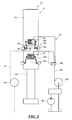
- is a schematic view showing the boom extension and contraction mechanism;
- Fig. 4
- is a side view showing a hose reel and a cord reel;
- Fig. 5
- is a top view showing the arrangement of the hose reel and the cord reel;
- Fig. 6
- is a back view showing the arrangement of the hose reel and the cord reel;
- Fig. 7
- is a drawing explaining the fleet angle; and
- Fig. 8
- is a schematic view showing the boom extending and contracting.
-
Figs. 1 to 8 show an embodiment of the present invention. With the present embodiment, amobile crane 1 will be described as a crane apparatus having a boom extension and contraction mechanism according to the present invention. - As shown in
Fig. 1 , themobile crane 1 includes avehicle 10 that runs on the ground, and acrane apparatus 20 as an operation part. - The
vehicle 10 haswheels 11 and runs by an engine (not shown) as a power source. In addition,outriggers 12 are provided on the right and left sides of the front part of thevehicle 10 and also on the right and left sides of the rear part of thevehicle 10 to prevent thevehicle 10 from overturning and support thevehicle 10 stably when the crane is working. Eachoutrigger 12 is movable outward in the width direction and also extendable downward by a hydraulic jack cylinder (not shown). The bottom ends of theoutriggers 12 contact the ground to support thevehicle 10 on the ground stably. - The
crane apparatus 20 includes aswivel base 21 that is pivotably provided in the center part of thevehicle 10 in the longitudinal direction and is configured to be able to swivel on a horizontal plane; aboom 22 provided to be able to rise and down with respect to theswivel base 21 and to be able to extend and contract; and acabin 23 provided in the front part of theswivel base 21 to run thevehicle 10 and operate thecrane apparatus 20 to work. - The
swivel base 21 is configured to be able to swivel with respect to thevehicle 10 by means of a ball bearing or roller bearing swivel support. Theswivel base 21 is driven by a hydraulic swivel motor (not shown). - The
boom 22 is constituted by a plurality ofboom members boom members next boom members boom members boom 22 according to the preset embodiment is constituted by six boom members, thebottom boom member 22a, thesecond boom member 22b, thethird boom member 22c, thefourth boom member 22d, thefifth boom member 22e, and thetop boom member 22f, which are arranged in the order from the base end of theboom 22. - The base end of the
bottom boom member 22a is swingably connected to abracket 21 a of theswivel base 21. Ahydraulic luffing cylinder 22g is connected between thebottom boom member 22a and thebracket 21 a, and extends and contracts to allow theboom 22 to rise and down. - A boom extension and
contraction mechanism 30 allows theboom 22 to extend and contract. - As shown in
Figs. 2 and3 , the boom extension and contraction mechanism includes: atelescopic cylinder 31 that shifts theboom members bottom boom member 22a; a cylinder-to-boom connection mechanism that removably connects between thetelescopic cylinder 31 and theboom members bottom boom member 22a; a plurality of boommember connection mechanism 33 that removably connect between theboom members boom members boom members member disconnection mechanism 34 that disconnects between theboom members boom members boom members - As shown in
Fig. 2 , thetelescopic cylinder 31 includes acylinder tube 31 a and acylinder rod 31 b. The front end of thecylinder rod 31 b is connected to the base end of thebottom boom member 22a in thebottom boom member 22a. By supplying the hydraulic oil discharged from ahydraulic pump 40, thecylinder tube 31a moves with respect to thecylinder rod 31 b in the direction in which theboom 22 extends and contracts. - As shown in
Fig. 3 , the cylinder-to-boom connection mechanism 32 is provided on the outer periphery of thecylinder tube 31 a thetelescopic cylinder 31. The cylinder-to-boom connection mechanism 32 includes a pair ofcylinder pins 32a that can engage theboom members bottom boom member 22a; and a cylinder-to-boomconnection switching cylinder 32b that releases the pair of cylinder pins 32a from engaging theboom members bottom boom member 22a. - As shown in
Fig. 2 , a cylinderpin engagement part 32c formed in a concave shape is provided in the base end side of each of theboom members bottom boom member 22a. Thecylinder pin 32a can engage each of the cylinderpin engagement part 32c. - The pair of
cylinder pins 32a can move in the radial direction of thecylinder tube 31 a. When being moved outward in the radial direction, the pair ofcylinder pins 32a engages the cylinderpin engagement parts 32c. Meanwhile, when being moved inward in the radial direction, the pair of cylinder pins 32 is released from engaging the cylinderpin engagement parts 32c. - The cylinder-to-boom
connection switching cylinder 32b is a spring return type of single acting cylinder that biases the cylinder pins 32a in the direction in which the cylinder pins 32a engage the cylinderpin engagement parts 32c. BY supplying the hydraulic oil, the cylinder-to-boomconnection switching cylinder 32b releases the cylinder pins 32a from engaging with thecylinder engagement parts 32c. - As shown in
Fig. 2 , each of the boommember connection mechanisms 33 includes: a boommember connection pin 33a provided in each of theboom members boom 22; and apin engagement hole 22b provided in each of theboom members boom 22, which can engage the boommember connection pin 33a. - As shown in
Fig. 2 , the boommember connection pin 33a is biased in the direction in which the front end of the boommember connection pin 33a engages thepin engagement hole 33b of thenext boom member lever engagement part 33c to engage adisconnection lever 33c of the boommember disconnection mechanism 34 described later is provided on the boommember connection pin 33a. - As shown in
Fig. 2 , thepin engagement holes 33b are provided for the base end sides and front end sides of theboom members pin engagement holes 33b are provided in positions to meet the protrusion length of theboom members next boom members boom members boom members - As shown in
Fig. 3 , the boommember disconnection mechanism 34 is provided on the outer periphery of thecylinder tube 31 a of thetelescopic cylinder 31, and has adisconnection lever 34a that can engage thelever engagement part 33c for any boommember connection pin 33a, and a boom member connection switching cylinder 34b that activates thedisconnection lever 34a. - The
disconnection lever 34a can engage thelever engagement part 33c of the boommember connection pin 33a at the position at which the pair ofcylinder pins 32a engages the cylinderpin engagement parts 32c. In addition, by driving the boom member connection switching cylinder 34b, thedisconnection lever 34a releases the boom member connection pins 33a from connecting between the boom members. - The boom member connection switching cylinder 34b is a spring return type of single acting cylinder. With the supply of the hydraulic oil, the boom member connection switching cylinder 34b activates the
disconnection lever 34a in the direction in which the boom member connection pins 33a are released from connecting between the boom members. - The boom extension and
contraction mechanism 30 further includes a hydraulicoil supply circuit 35 for supplying the cylinder-to-boomconnection switching cylinder 32b and the boom member connection switching cylinder 34b with the hydraulic oil discharged from thehydraulic pump 40. - As shown in
Fig. 3 , the hydraulicoil supply circuit 35 includes ahydraulic hose 35a for flowing the hydraulic oil discharged from thehydraulic pump 40 into the cylinder-to-boomconnection switching cylinder 32b and the boom member connection switching cylinder 34b; and a flowpassage switching valve 35b for switching the flow passage of the hydraulic oil discharged from thehydraulic hose 35a between the cylinder-to-boomconnection switching cylinder 32b and the boom member connection switching cylinder 34b. - The
hydraulic hose 35a is made of a flexible material and has a length that can supply the hydraulic oil to the cylinder-to-boomconnection switching cylinder 32b and the boom member connection switching cylinder 34b while thetelescopic cylinder 31 is maximally extended. Thehydraulic hose 35a wound around thehose reel 35c is reeled out from thehose reel 35c as thetelescopic cylinder 31 is extending, and is reeled off on thehose reel 35c as thetelescopic cylinder 31 is contracting. - As shown in
Figs. 4 to 6 , thehose reel 35c is mounted on thebracket 21 a and located below the base end of thebottom boom member 22a. Thehose reel 35c has a dimension in the direction of the rotating axis that allows thehydraulic hose 35a to be wound around thehose reel 35c in a single layer in the direction of the rotating axis and has a dimension in the radial direction that allows thehydraulic hose 35a to be wound around thehose reel 35c in layers outward in the radial direction. Thehydraulic hose 35a wound around thehose reel 35c is guided by afirst sheave 35d and extends to the cylinder-to-boomconnection switching cylinder 32b and the boom member connection switching cylinder 34b side. Thefirst sheave 35d is rotatably provided on the base end of thebottom boom member 22a located above thehose reel 35c. - As shown in
Fig. 3 , the boom extension andcontraction mechanism 30 further includes a plurality of proximity switches 36 that detect which of theboom members connection switching cylinder 32b and the boom member connection switching cylinder 34b. These proximity switches 36 and a solenoid that drives the flowpassage switching valve 35b are connected to a controller provided in, for example, thevehicle 10 via thecable 37. Thecable 37 is constituted by a plurality of flexible signal lines and has a length that can reach the proximity switches 36 and the flowpassage switching valve 35b whiletelescopic cylinder 31 is maximally extended. Thecable 37 wound around thecord reel 37a is reeled out from thecord reel 37a as thetelescopic cylinder 31 is extending, and is reeled off on thecord reel 37a as thetelescopic cylinder 31 is contracting. - As shown in
Figs. 4 to 6 , thecord reel 37a is mounted on thebracket 21 a and located below the base end of thebottom boom member 22a and in front of thehose reel 35c. Thecord reel 37a has a dimension in the direction of the rotating axis that allows thecable 37 to be wound around thecord reel 37a in a single layer in the direction of the rotating axis. Thecable 37 wound around thecord reel 37a is guided by aroller guide 37b and asecond sheave 37c and extends to the proximity switches 36 and the flowchannel switching valve 35b side. Theroller guide 37b is rotatably provided on thebracket 21 a at a position behind and obliquely above thecord reel 37a. Thesecond sheave 37c is rotatably provided on the base end of thebottom boom member 22a located above theroller guide 37b on the same axis as thefirst sheave 35d. - Here, the relationship between the
hose reel 35c and thefirst sheave 35d, and the relationship between thecord reel 37a and thesecond sheave 37c have to satisfy so-called "fleet angle". - As shown in
Fig. 7 , the fleet angle means angle θ made by line A connecting the center of the sheave in the direction of the rotating axis and the center of the reel in the direction of the rotating axis and line B connecting the center of the sheave in the direction of the rotating axis and the inner surface of a flange in the direction of the rotating axis of the reel. With the present embodiment, the relationship between the positions of thehose reel 35c and thefirst sheave 35d, the relationship between the positions of thecord reel 37a and thesecond sheave 37c, and the dimensions of thehose reel 35c and thecord reel 37a in the direction of the rotating axis are determined such that the fleet angle is within two degrees. - With the boom extension and contraction mechanism for a crane apparatus having the above-described configuration, in order to extend the
boom 22, theboom members boom members boom member 22f that is located in the front end side. Meanwhile, in order to contract theboom 22, theboom members boom members - In order to extend and contract the
boom 22, the boom extension andcontraction mechanism 30 first supplies the cylinder-to-boomconnection switching cylinder 32b with the hydraulic oil to release the cylinder pins 32a from engaging the boom member and then drive the telescopic cylinder 31 (seeFig. 8A ). Next, the boom extension andcontraction mechanism 30 shifts the cylinder pins 32a to the position at which the cylinder pins 32a face the cylinderpin engagement parts 32c of the boom member intended to be shifted by driving thetelescopic cylinder 31, and stops supplying the hydraulic oil to the cylinder-to-boomconnection switching cylinder 32b to release the cylinder pins 32a from disconnecting from the boom member. As a result, the cylinder pins 32a engage the cylinderpin engagement part 32c for the boom member intended to be shifted (seeFig. 8B ). After the cylinder pins 32a have engaged the cylinderpin engagement parts 32c, the boom extension andcontraction mechanism 30 disconnects between the boom member to be shifted and the next boom member in the base end side by supplying the boom member connection switching cylinder 34b with the hydraulic oil. In this state, the boom extension andcontraction mechanism 30 drives thetelescopic cylinder 31 to allow theboom 22 to extend and contract (seeFig. 8C ). After having shifted the intended boom member to a predetermined position, the boom extension andcontraction mechanism 30 stop supplying the boom member connection switching cylinder 34b with the hydraulic oil, and connect the shifted boom member to the next boom member in the base end side. - As described above, the boom extension and contraction mechanism for a crane apparatus according to the present embodiment includes: a
hydraulic hose 35a configured to supply hydraulic oil from theswivel base side 21 to the cylinder-to-boomconnection switching cylinder 32b and the boom member connection switching cylinder 34b; a flowpassage switching valve 35b configured to switch the flow passage of the hydraulic oil supplied via thehydraulic hose 35a between the cylinder-to-boomconnection switching cylinder 32b side and the boom member connection switching cylinder 34b side; ahose reel 35c configured to reel out thehydraulic hose 35a as thetelescopic cylinder 31 is extending, and reel off thehydraulic hose 35a astelescopic cylinder 31 is contracting; acable 37 used to supply power from theswivel base 21 side to the solenoid for driving the flowpassage switching valve 35b and to transmit signals from the proximity switches 36 to theswivel base 21 side; and acord reel 37a configured to reel off thecable 37 as thetelescopic cylinder 31 is extending and to reel off thecable 37 as thetelescopic cylinder 31 is contracting. Thehose reel 35c and thecord reel 37a are arranged on theswivel base 21 in the direction in which the boom 2 extends and contracts. By this means, it is possible to increase the dimension of thehose reel 35c in the direction of the rotating axis while reducing the dimension of thehose reel 35c in the radial direction. Therefore, it is possible to reduce the length over which thehose reel 35c protrude from the back of theswivel base 21, and consequently to reduce the angle of traverse in the back of theswivel base 21 with a simple structure. Moreover, it is possible to place thehydraulic hose 35a and thecable 37 near one another and extend them to thecylinder tube 31 a side, and therefore to reduce the size of theboom 22 in the width direction. - Here, with the present embodiment, a configuration has been described where the boom extension and contraction mechanism according to the present invention is applied to a mobile crane. However, it is by no means limiting, but the boom extension and contraction mechanism according to the present invention is applicable to a fixed crane apparatus.
Claims (1)
- A boom extension and contraction mechanism (30) for a crane apparatus (20) comprising:a boom (22) including a plurality of boom members (22a, 22b, 22c, 22d, 22e, and 22f), the boom (22) extending and contracting by shifting next boom members (22b, 22c, 22d, 22e, and 22f) in front of respective ones (22a, 22b, 22c, 22d, and 22e) with respect to the boom members (22a, 22b, 22c, 22d, 22e) other than a top boom member (22f);a base (21) configured to support a base end of a bottom boom member (22a);a telescopic cylinder (31) including a cylinder rod (31 b) and a cylinder tube (31 a), one of the cylinder rod (31 b) and the cylinder tube (31 a) being connected to the bottom boom member (22a) to extend and contract the boom (22);a cylinder-to-boom connection mechanism (32) configured to be able to connect and disconnect between the other of the cylinder rod (31 b) and the cylinder tube (32a) and the boom members (22b, 22c, 22d, 22e, and, 22f) other than the bottom boom member (22a);a boom member connection mechanism (33) configured to be able to connect between the boom members (22a, 22b, 22c, 22d, 22e, and 22f) next to one another and release the boom members (22a, 22b, 22c, 22d, 22e, and 22f) from being connected to one another;a cylinder-to-boom connection switching cylinder (32b) configured to allow the cylinder-to-boom connection mechanism (32) to perform one of a connecting operation and a disconnecting operation between the telescopic cylinder (31) and a boom member (22a, 22b, 22c, 22d, 22e, and 22f) by supplying hydraulic oil, and to allow the cylinder-to-boom connection mechanism (32) to perform the other of the connecting operation and the disconnecting operation between the telescopic cylinder (31) and the boom member (22a, 22b, 22c, 22d, 22e, and 22f) by stopping supplying the hydraulic oil;a boom member connection switching cylinder (34b) configured to allow the boom member connection mechanism (33) to perform one of a connecting operation and a disconnecting operation between the boom members (22a, 22b, 22c, 22d, 22e, and 22f) next to one another by supplying the hydraulic oil, and to allow the boom member connection mechanism (33) to perform the other of the connecting operation and the disconnecting operation between the boom members (22a, 22b, 22c, 22d, 22e, and 22f) next to one another by stopping supplying the hydraulic oil;a hydraulic hose (35a) configured to supply the hydraulic oil from the base (21) side to the cylinder-to-boom connection switching cylinder (32b) and the boom member connection switching cylinder (34b);a flow passage switching mechanism (35b) configured to switch a flow passage of the hydraulic oil supplied via the hydraulic hose (35a) between the cylinder-to-boom connection switching cylinder (32b) side and the boom member connection switching cylinder side (34b);a hose reel (35c) configured to reel out the hydraulic hose (35a) as the telescopic cylinder (31) is extending, and to reel off the hydraulic hose (35a) as the telescopic cylinder (31) is contracting;a cable (37) used to supply power from the base (21) side to equipment provided in the other of the cylinder rod (31 b) and the cylinder tube (31 a) of the telescopic cylinder (31), and to transmit a signal from the equipment to the base (21) side; anda cord reel (37a) configured to reel out the cable (37) as the telescopic cylinder (31) is extending and to reel off the cable (37) as the telescopic cylinder (31) is contracting,wherein the hose reel (35c) and the cord reel (37a) are arranged on the base (21) in a direction in which the boom (22) extends and contracts.
Applications Claiming Priority (1)
| Application Number | Priority Date | Filing Date | Title |
|---|---|---|---|
| JP2013179061A JP6223071B2 (en) | 2013-08-30 | 2013-08-30 | Boom telescopic mechanism of crane equipment |
Publications (2)
| Publication Number | Publication Date |
|---|---|
| EP2842903A1 true EP2842903A1 (en) | 2015-03-04 |
| EP2842903B1 EP2842903B1 (en) | 2016-08-17 |
Family
ID=51383633
Family Applications (1)
| Application Number | Title | Priority Date | Filing Date |
|---|---|---|---|
| EP14181773.4A Active EP2842903B1 (en) | 2013-08-30 | 2014-08-21 | Boom extension and contraction mechanism for crane apparatus |
Country Status (6)
| Country | Link |
|---|---|
| US (1) | US9796566B2 (en) |
| EP (1) | EP2842903B1 (en) |
| JP (1) | JP6223071B2 (en) |
| CN (1) | CN104418249B (en) |
| AU (1) | AU2014218354B2 (en) |
| CA (1) | CA2860737C (en) |
Families Citing this family (12)
| Publication number | Priority date | Publication date | Assignee | Title |
|---|---|---|---|---|
| US10604386B2 (en) * | 2016-03-03 | 2020-03-31 | Tadano Ltd. | Expansion/contraction mechanism |
| JP6668832B2 (en) * | 2016-03-07 | 2020-03-18 | 株式会社タダノ | Boom telescopic device |
| JP6627898B2 (en) * | 2018-02-16 | 2020-01-08 | 株式会社タダノ | crane |
| JP2019210071A (en) * | 2018-05-31 | 2019-12-12 | 株式会社タダノ | crane |
| DE102018117630B4 (en) * | 2018-07-20 | 2020-07-09 | Manitowoc Crane Group France Sas | Crane telescope locking device |
| CN109368497A (en) * | 2018-12-21 | 2019-02-22 | 陈奕松 | A wiring device for a crane telescopic boom |
| WO2020183686A1 (en) * | 2019-03-14 | 2020-09-17 | 株式会社タダノ | Expansion device and crane |
| CN113646251B (en) * | 2019-04-04 | 2024-04-09 | 株式会社多田野 | Working machine |
| CN110240021B (en) * | 2019-06-28 | 2021-06-18 | 三一汽车起重机械有限公司 | Monitoring method, processor and system for cable in single-cylinder bolt type telescopic arm |
| CN111270641B (en) * | 2020-03-28 | 2021-01-22 | 江苏博世建设有限公司 | Urban road surface drainage equipment |
| CN113063381B (en) * | 2021-03-12 | 2022-12-02 | 三一汽车起重机械有限公司 | Crane arm length measuring method and device, electronic equipment and storage medium |
| JP2022167829A (en) * | 2021-04-23 | 2022-11-04 | タダノ デマグ ゲーエムベーハー | Vehicle crane having telescopic jib having fixing and lock unit |
Citations (4)
| Publication number | Priority date | Publication date | Assignee | Title |
|---|---|---|---|---|
| JP2002293494A (en) * | 2001-03-30 | 2002-10-09 | Tadano Ltd | Control device for boom extension mechanism |
| JP2002332194A (en) | 2001-05-08 | 2002-11-22 | Tadano Ltd | Controller for telescopic mechanism |
| JP2004244196A (en) * | 2003-02-17 | 2004-09-02 | Tadano Ltd | Control device of boom telescopic mechanism |
| JP2010184754A (en) * | 2009-02-10 | 2010-08-26 | Tadano Ltd | Operation control device of boom telescopic mechanism |
Family Cites Families (42)
| Publication number | Priority date | Publication date | Assignee | Title |
|---|---|---|---|---|
| US2310887A (en) * | 1941-05-06 | 1943-02-09 | Armored Tank Corp | Hook-on-and-release mechanism for fighting tanks |
| US3638806A (en) * | 1969-08-01 | 1972-02-01 | Bliss & Laughlin Ind | Portable crane with extendable boom |
| US3701439A (en) * | 1970-05-01 | 1972-10-31 | Pettibone Corp | System for automatically paying-out line proportional to extension of crane boom |
| US3657969A (en) * | 1970-07-10 | 1972-04-25 | Case Co J I | Hydraulic control system for extensible crane |
| US3770138A (en) * | 1971-04-15 | 1973-11-06 | Fmc Corp | Sequenced crane boom |
| US3792780A (en) * | 1971-12-02 | 1974-02-19 | Kidde & Co Walter | Mechanism for positioning and restricting crane control levers to prevent dangerous load condition |
| US3771668A (en) * | 1972-04-24 | 1973-11-13 | Harnischfeger Corp | Tension scale system for lifting cable of a telescoping boom crane |
| CA957354A (en) * | 1972-06-05 | 1974-11-05 | Fathom Oceanology Limited | Cable transfer apparatus |
| US3777629A (en) * | 1972-09-18 | 1973-12-11 | Harnischfeger Corp | Hydraulic cylinder for telescopic boom |
| US3876045A (en) * | 1972-09-27 | 1975-04-08 | Otto H Knarreborg | Reel device for extension cord |
| US4036372A (en) * | 1975-12-15 | 1977-07-19 | Clark Equipment Company | Extension and retraction means for the telescopic boom assembly of a crane |
| US4219121A (en) * | 1978-02-21 | 1980-08-26 | Burro-Badger Corporation | Safety system for use in association with material handling equipment |
| DE2926292A1 (en) * | 1979-06-29 | 1981-01-08 | Harnischfeger Gmbh | PARTICULARLY MOBILE TELESCOPIC BOOM CRANE |
| US4395192A (en) * | 1981-01-19 | 1983-07-26 | The Warner & Swasey Company | Boom cylinder |
| US4434902A (en) * | 1981-03-05 | 1984-03-06 | Fmc Corporation | Apparatus for extending and retracting a manual boom section |
| US4436190A (en) * | 1981-07-29 | 1984-03-13 | Combustion Engineering, Inc. | Torsionless multiple connector reel device |
| US4954041A (en) * | 1987-10-21 | 1990-09-04 | Lull Corp. | Triple section telescopic boom materials handling vehicle |
| US4993564A (en) * | 1989-05-17 | 1991-02-19 | Blatt John A | Quick disconnect tooling mount |
| US5501346A (en) * | 1991-11-11 | 1996-03-26 | Palfinger Aktiengesellschaft | Multistage telescope boom |
| JP2841016B2 (en) * | 1993-11-08 | 1998-12-24 | 小松メック株式会社 | Operation control method and device for reach tower crane |
| GB9326347D0 (en) * | 1993-12-23 | 1994-02-23 | Grove Europ Limited | Improvements in and relating to telescopic booms |
| DE4344795A1 (en) * | 1993-12-28 | 1995-06-29 | Liebherr Werk Ehingen | Mobile crane with a telescopic boom |
| US5660495A (en) * | 1995-11-02 | 1997-08-26 | Japan Skyrobot Co., Ltd | Locking-unlocking mechanism for telescopic device |
| DE19653502C2 (en) * | 1996-12-20 | 2000-06-21 | Grove Us Llc | Device for locking or releasing the locking of shots of a telescopic boom for a mobile crane |
| DE19811813B4 (en) * | 1998-03-18 | 2005-11-24 | Grove U.S. LLC (n.d.Ges.d.Staates Delaware) | Lateral boom interlock |
| US6029559A (en) * | 1998-04-06 | 2000-02-29 | Grove U.S. L.L.C. | Telescoping system with multiple single-stage telescopic cylinders |
| US5877693A (en) * | 1998-05-27 | 1999-03-02 | Grove U.S. L.L.C. | Method and apparatus for measuring the length of a multi-section telescopic boom |
| FR2797862B1 (en) * | 1999-09-01 | 2001-11-16 | Ppm | METHOD OF TELESCOPING A CRANE BOOM, DEVICE FOR ITS IMPLEMENTATION AND CRANE BOOM BY APPLYING |
| CA2331105A1 (en) * | 2000-01-21 | 2001-07-21 | National Crane Corporation | Anti-two block wire internal to crane telescopic boom |
| DE10022373B4 (en) * | 2000-05-08 | 2005-11-24 | Grove U.S. Llc | Locking and operating unit for side arm lock |
| DE20216079U1 (en) * | 2002-07-10 | 2003-03-13 | Demag Cranes & Components GmbH, 58300 Wetter | Suspension control device |
| JP4287665B2 (en) * | 2003-02-14 | 2009-07-01 | 株式会社タダノ | Telescopic boom of crane truck |
| WO2005021415A1 (en) * | 2003-08-22 | 2005-03-10 | Terex-Demag Gmbh & Co. Kg | Mobile crane jib with self-sufficient hydraulic unit disposed thereon |
| GB0416336D0 (en) * | 2004-07-22 | 2004-08-25 | Bamford Excavators Ltd | Method of operating a machine |
| DE102009006292B4 (en) * | 2009-01-27 | 2015-03-26 | Manitowoc Crane Group France Sas | Locking system for telescopic crane jib with sliding locking unit |
| DE102009009944B4 (en) * | 2009-02-20 | 2011-02-24 | Terex-Demag Gmbh | Securing and bolting unit |
| JP4998589B2 (en) * | 2010-05-18 | 2012-08-15 | コベルコクレーン株式会社 | Boom telescopic stage number switching control device |
| DE202010013544U1 (en) * | 2010-09-23 | 2012-01-19 | Liebherr-Werk Ehingen Gmbh | Telescopic weft and crane with telescopic weft |
| RU2547492C2 (en) * | 2010-12-17 | 2015-04-10 | Тадано Фаун Гмбх | Movable telescopic lifting crane |
| DE102013011180B4 (en) * | 2013-07-04 | 2020-09-10 | Liebherr-Werk Ehingen Gmbh | Collar storage for a telescopic boom as well as telescopic boom and crane |
| EP2835336B1 (en) * | 2013-08-09 | 2018-02-28 | Manitowoc Crane Group France SAS | Mechanical locking head |
| DE202013010381U1 (en) * | 2013-11-11 | 2013-11-26 | Terex Cranes Germany Gmbh | Drive a sliding gate of a locking system of a Teleskopiersystems a crane jib |
-
2013
- 2013-08-30 JP JP2013179061A patent/JP6223071B2/en active Active
-
2014
- 2014-08-12 US US14/457,885 patent/US9796566B2/en active Active
- 2014-08-20 CN CN201410412095.8A patent/CN104418249B/en active Active
- 2014-08-21 EP EP14181773.4A patent/EP2842903B1/en active Active
- 2014-08-26 AU AU2014218354A patent/AU2014218354B2/en active Active
- 2014-08-27 CA CA2860737A patent/CA2860737C/en active Active
Patent Citations (4)
| Publication number | Priority date | Publication date | Assignee | Title |
|---|---|---|---|---|
| JP2002293494A (en) * | 2001-03-30 | 2002-10-09 | Tadano Ltd | Control device for boom extension mechanism |
| JP2002332194A (en) | 2001-05-08 | 2002-11-22 | Tadano Ltd | Controller for telescopic mechanism |
| JP2004244196A (en) * | 2003-02-17 | 2004-09-02 | Tadano Ltd | Control device of boom telescopic mechanism |
| JP2010184754A (en) * | 2009-02-10 | 2010-08-26 | Tadano Ltd | Operation control device of boom telescopic mechanism |
Also Published As
| Publication number | Publication date |
|---|---|
| JP6223071B2 (en) | 2017-11-01 |
| CN104418249A (en) | 2015-03-18 |
| CA2860737C (en) | 2016-07-05 |
| EP2842903B1 (en) | 2016-08-17 |
| AU2014218354A1 (en) | 2015-03-19 |
| US9796566B2 (en) | 2017-10-24 |
| CA2860737A1 (en) | 2015-02-28 |
| JP2015048168A (en) | 2015-03-16 |
| US20150060385A1 (en) | 2015-03-05 |
| CN104418249B (en) | 2016-10-05 |
| AU2014218354B2 (en) | 2015-12-24 |
Similar Documents
| Publication | Publication Date | Title |
|---|---|---|
| EP2842903B1 (en) | Boom extension and contraction mechanism for crane apparatus | |
| EP3147252B1 (en) | Automatic boom telescopic motion apparatus for working machine | |
| WO2009137484A1 (en) | Fork apparatus for handling cotton bales | |
| EP3424868B1 (en) | Expansion/contraction mechanism | |
| CN104250982A (en) | Reel system within boom | |
| CN106365055A (en) | Plug-type extending-and-contracting system and lifting machine | |
| JP6793726B2 (en) | Mobile crane | |
| JP6635244B1 (en) | Telescopic devices and cranes | |
| KR20120074504A (en) | Fork lift within mast having rear-arrangement structure of hydraulic hose | |
| US10787345B2 (en) | Crane | |
| US5678707A (en) | Mechanism for rotating a crane turret through a 500° arc | |
| JP6258633B2 (en) | Cable winding device for construction machinery and telescopic boom device for construction machinery | |
| CN221027502U (en) | Telescopic boom and telescopic boom forklift | |
| JP2019131341A (en) | Lever device | |
| JP2007015841A (en) | Long body feeding and winding device for mobile work vehicle | |
| JP7110753B2 (en) | Device for increasing tension of luffing rope and method for increasing tension of luffing rope | |
| JP7119394B2 (en) | operating valves and cranes | |
| AU696821C (en) | Mechanism for rotating a crane turret through a 500 degree arc | |
| JP5891044B2 (en) | Full free mast hydraulic system | |
| JP2019127330A (en) | Loading type truck crane | |
| ITRE20120037A1 (en) | HYDRAULIC SYSTEM THAT MAINTAINS THE ROPE LENGTH ON THE END OF A TELESCOPIC ARM EQUIPPED WITH A HYDRAULIC WINCH, DURING THE VARIATION OF TELESCOPIC EXTENSION |
Legal Events
| Date | Code | Title | Description |
|---|---|---|---|
| 17P | Request for examination filed |
Effective date: 20140821 |
|
| AK | Designated contracting states |
Kind code of ref document: A1 Designated state(s): AL AT BE BG CH CY CZ DE DK EE ES FI FR GB GR HR HU IE IS IT LI LT LU LV MC MK MT NL NO PL PT RO RS SE SI SK SM TR |
|
| AX | Request for extension of the european patent |
Extension state: BA ME |
|
| PUAI | Public reference made under article 153(3) epc to a published international application that has entered the european phase |
Free format text: ORIGINAL CODE: 0009012 |
|
| GRAP | Despatch of communication of intention to grant a patent |
Free format text: ORIGINAL CODE: EPIDOSNIGR1 |
|
| R17P | Request for examination filed (corrected) |
Effective date: 20150902 |
|
| RBV | Designated contracting states (corrected) |
Designated state(s): AL AT BE BG CH CY CZ DE DK EE ES FI FR GB GR HR HU IE IS IT LI LT LU LV MC MK MT NL NO PL PT RO RS SE SI SK SM TR |
|
| RIC1 | Information provided on ipc code assigned before grant |
Ipc: B66C 23/70 20060101AFI20150916BHEP |
|
| INTG | Intention to grant announced |
Effective date: 20151005 |
|
| GRAS | Grant fee paid |
Free format text: ORIGINAL CODE: EPIDOSNIGR3 |
|
| INTG | Intention to grant announced |
Effective date: 20160128 |
|
| GRAA | (expected) grant |
Free format text: ORIGINAL CODE: 0009210 |
|
| AK | Designated contracting states |
Kind code of ref document: B1 Designated state(s): AL AT BE BG CH CY CZ DE DK EE ES FI FR GB GR HR HU IE IS IT LI LT LU LV MC MK MT NL NO PL PT RO RS SE SI SK SM TR |
|
| REG | Reference to a national code |
Ref country code: GB Ref legal event code: FG4D |
|
| REG | Reference to a national code |
Ref country code: CH Ref legal event code: EP |
|
| REG | Reference to a national code |
Ref country code: IE Ref legal event code: FG4D |
|
| REG | Reference to a national code |
Ref country code: AT Ref legal event code: REF Ref document number: 820859 Country of ref document: AT Kind code of ref document: T Effective date: 20160915 |
|
| REG | Reference to a national code |
Ref country code: DE Ref legal event code: R096 Ref document number: 602014003077 Country of ref document: DE |
|
| REG | Reference to a national code |
Ref country code: NL Ref legal event code: MP Effective date: 20160817 |
|
| REG | Reference to a national code |
Ref country code: LT Ref legal event code: MG4D |
|
| REG | Reference to a national code |
Ref country code: AT Ref legal event code: MK05 Ref document number: 820859 Country of ref document: AT Kind code of ref document: T Effective date: 20160817 |
|
| PG25 | Lapsed in a contracting state [announced via postgrant information from national office to epo] |
Ref country code: NL Free format text: LAPSE BECAUSE OF FAILURE TO SUBMIT A TRANSLATION OF THE DESCRIPTION OR TO PAY THE FEE WITHIN THE PRESCRIBED TIME-LIMIT Effective date: 20160817 Ref country code: NO Free format text: LAPSE BECAUSE OF FAILURE TO SUBMIT A TRANSLATION OF THE DESCRIPTION OR TO PAY THE FEE WITHIN THE PRESCRIBED TIME-LIMIT Effective date: 20161117 Ref country code: HR Free format text: LAPSE BECAUSE OF FAILURE TO SUBMIT A TRANSLATION OF THE DESCRIPTION OR TO PAY THE FEE WITHIN THE PRESCRIBED TIME-LIMIT Effective date: 20160817 Ref country code: LT Free format text: LAPSE BECAUSE OF FAILURE TO SUBMIT A TRANSLATION OF THE DESCRIPTION OR TO PAY THE FEE WITHIN THE PRESCRIBED TIME-LIMIT Effective date: 20160817 Ref country code: IT Free format text: LAPSE BECAUSE OF FAILURE TO SUBMIT A TRANSLATION OF THE DESCRIPTION OR TO PAY THE FEE WITHIN THE PRESCRIBED TIME-LIMIT Effective date: 20160817 Ref country code: RS Free format text: LAPSE BECAUSE OF FAILURE TO SUBMIT A TRANSLATION OF THE DESCRIPTION OR TO PAY THE FEE WITHIN THE PRESCRIBED TIME-LIMIT Effective date: 20160817 Ref country code: FI Free format text: LAPSE BECAUSE OF FAILURE TO SUBMIT A TRANSLATION OF THE DESCRIPTION OR TO PAY THE FEE WITHIN THE PRESCRIBED TIME-LIMIT Effective date: 20160817 |
|
| PG25 | Lapsed in a contracting state [announced via postgrant information from national office to epo] |
Ref country code: AT Free format text: LAPSE BECAUSE OF FAILURE TO SUBMIT A TRANSLATION OF THE DESCRIPTION OR TO PAY THE FEE WITHIN THE PRESCRIBED TIME-LIMIT Effective date: 20160817 Ref country code: PT Free format text: LAPSE BECAUSE OF FAILURE TO SUBMIT A TRANSLATION OF THE DESCRIPTION OR TO PAY THE FEE WITHIN THE PRESCRIBED TIME-LIMIT Effective date: 20161219 Ref country code: SE Free format text: LAPSE BECAUSE OF FAILURE TO SUBMIT A TRANSLATION OF THE DESCRIPTION OR TO PAY THE FEE WITHIN THE PRESCRIBED TIME-LIMIT Effective date: 20160817 Ref country code: ES Free format text: LAPSE BECAUSE OF FAILURE TO SUBMIT A TRANSLATION OF THE DESCRIPTION OR TO PAY THE FEE WITHIN THE PRESCRIBED TIME-LIMIT Effective date: 20160817 Ref country code: BE Free format text: LAPSE BECAUSE OF NON-PAYMENT OF DUE FEES Effective date: 20160831 Ref country code: LV Free format text: LAPSE BECAUSE OF FAILURE TO SUBMIT A TRANSLATION OF THE DESCRIPTION OR TO PAY THE FEE WITHIN THE PRESCRIBED TIME-LIMIT Effective date: 20160817 Ref country code: GR Free format text: LAPSE BECAUSE OF FAILURE TO SUBMIT A TRANSLATION OF THE DESCRIPTION OR TO PAY THE FEE WITHIN THE PRESCRIBED TIME-LIMIT Effective date: 20161118 Ref country code: PL Free format text: LAPSE BECAUSE OF FAILURE TO SUBMIT A TRANSLATION OF THE DESCRIPTION OR TO PAY THE FEE WITHIN THE PRESCRIBED TIME-LIMIT Effective date: 20160817 |
|
| PG25 | Lapsed in a contracting state [announced via postgrant information from national office to epo] |
Ref country code: EE Free format text: LAPSE BECAUSE OF FAILURE TO SUBMIT A TRANSLATION OF THE DESCRIPTION OR TO PAY THE FEE WITHIN THE PRESCRIBED TIME-LIMIT Effective date: 20160817 Ref country code: RO Free format text: LAPSE BECAUSE OF FAILURE TO SUBMIT A TRANSLATION OF THE DESCRIPTION OR TO PAY THE FEE WITHIN THE PRESCRIBED TIME-LIMIT Effective date: 20160817 |
|
| REG | Reference to a national code |
Ref country code: DE Ref legal event code: R097 Ref document number: 602014003077 Country of ref document: DE |
|
| PG25 | Lapsed in a contracting state [announced via postgrant information from national office to epo] |
Ref country code: DK Free format text: LAPSE BECAUSE OF FAILURE TO SUBMIT A TRANSLATION OF THE DESCRIPTION OR TO PAY THE FEE WITHIN THE PRESCRIBED TIME-LIMIT Effective date: 20160817 Ref country code: BG Free format text: LAPSE BECAUSE OF FAILURE TO SUBMIT A TRANSLATION OF THE DESCRIPTION OR TO PAY THE FEE WITHIN THE PRESCRIBED TIME-LIMIT Effective date: 20161117 Ref country code: SM Free format text: LAPSE BECAUSE OF FAILURE TO SUBMIT A TRANSLATION OF THE DESCRIPTION OR TO PAY THE FEE WITHIN THE PRESCRIBED TIME-LIMIT Effective date: 20160817 Ref country code: CZ Free format text: LAPSE BECAUSE OF FAILURE TO SUBMIT A TRANSLATION OF THE DESCRIPTION OR TO PAY THE FEE WITHIN THE PRESCRIBED TIME-LIMIT Effective date: 20160817 Ref country code: SK Free format text: LAPSE BECAUSE OF FAILURE TO SUBMIT A TRANSLATION OF THE DESCRIPTION OR TO PAY THE FEE WITHIN THE PRESCRIBED TIME-LIMIT Effective date: 20160817 Ref country code: BE Free format text: LAPSE BECAUSE OF FAILURE TO SUBMIT A TRANSLATION OF THE DESCRIPTION OR TO PAY THE FEE WITHIN THE PRESCRIBED TIME-LIMIT Effective date: 20160817 |
|
| REG | Reference to a national code |
Ref country code: IE Ref legal event code: MM4A |
|
| PLBE | No opposition filed within time limit |
Free format text: ORIGINAL CODE: 0009261 |
|
| STAA | Information on the status of an ep patent application or granted ep patent |
Free format text: STATUS: NO OPPOSITION FILED WITHIN TIME LIMIT |
|
| PG25 | Lapsed in a contracting state [announced via postgrant information from national office to epo] |
Ref country code: MC Free format text: LAPSE BECAUSE OF FAILURE TO SUBMIT A TRANSLATION OF THE DESCRIPTION OR TO PAY THE FEE WITHIN THE PRESCRIBED TIME-LIMIT Effective date: 20160817 |
|
| REG | Reference to a national code |
Ref country code: FR Ref legal event code: ST Effective date: 20170612 |
|
| 26N | No opposition filed |
Effective date: 20170518 |
|
| PG25 | Lapsed in a contracting state [announced via postgrant information from national office to epo] |
Ref country code: FR Free format text: LAPSE BECAUSE OF NON-PAYMENT OF DUE FEES Effective date: 20161017 Ref country code: IE Free format text: LAPSE BECAUSE OF NON-PAYMENT OF DUE FEES Effective date: 20160821 |
|
| PG25 | Lapsed in a contracting state [announced via postgrant information from national office to epo] |
Ref country code: LU Free format text: LAPSE BECAUSE OF NON-PAYMENT OF DUE FEES Effective date: 20160821 Ref country code: SI Free format text: LAPSE BECAUSE OF FAILURE TO SUBMIT A TRANSLATION OF THE DESCRIPTION OR TO PAY THE FEE WITHIN THE PRESCRIBED TIME-LIMIT Effective date: 20160817 |
|
| REG | Reference to a national code |
Ref country code: CH Ref legal event code: PL |
|
| PG25 | Lapsed in a contracting state [announced via postgrant information from national office to epo] |
Ref country code: LI Free format text: LAPSE BECAUSE OF NON-PAYMENT OF DUE FEES Effective date: 20170831 Ref country code: CH Free format text: LAPSE BECAUSE OF NON-PAYMENT OF DUE FEES Effective date: 20170831 |
|
| PG25 | Lapsed in a contracting state [announced via postgrant information from national office to epo] |
Ref country code: HU Free format text: LAPSE BECAUSE OF FAILURE TO SUBMIT A TRANSLATION OF THE DESCRIPTION OR TO PAY THE FEE WITHIN THE PRESCRIBED TIME-LIMIT; INVALID AB INITIO Effective date: 20140821 |
|
| PG25 | Lapsed in a contracting state [announced via postgrant information from national office to epo] |
Ref country code: CY Free format text: LAPSE BECAUSE OF FAILURE TO SUBMIT A TRANSLATION OF THE DESCRIPTION OR TO PAY THE FEE WITHIN THE PRESCRIBED TIME-LIMIT Effective date: 20160817 Ref country code: IS Free format text: LAPSE BECAUSE OF FAILURE TO SUBMIT A TRANSLATION OF THE DESCRIPTION OR TO PAY THE FEE WITHIN THE PRESCRIBED TIME-LIMIT Effective date: 20160817 Ref country code: MK Free format text: LAPSE BECAUSE OF FAILURE TO SUBMIT A TRANSLATION OF THE DESCRIPTION OR TO PAY THE FEE WITHIN THE PRESCRIBED TIME-LIMIT Effective date: 20160817 Ref country code: MT Free format text: LAPSE BECAUSE OF NON-PAYMENT OF DUE FEES Effective date: 20160831 |
|
| PG25 | Lapsed in a contracting state [announced via postgrant information from national office to epo] |
Ref country code: TR Free format text: LAPSE BECAUSE OF FAILURE TO SUBMIT A TRANSLATION OF THE DESCRIPTION OR TO PAY THE FEE WITHIN THE PRESCRIBED TIME-LIMIT Effective date: 20160817 Ref country code: AL Free format text: LAPSE BECAUSE OF FAILURE TO SUBMIT A TRANSLATION OF THE DESCRIPTION OR TO PAY THE FEE WITHIN THE PRESCRIBED TIME-LIMIT Effective date: 20160817 |
|
| GBPC | Gb: european patent ceased through non-payment of renewal fee |
Effective date: 20180821 |
|
| PG25 | Lapsed in a contracting state [announced via postgrant information from national office to epo] |
Ref country code: GB Free format text: LAPSE BECAUSE OF NON-PAYMENT OF DUE FEES Effective date: 20180821 |
|
| PGFP | Annual fee paid to national office [announced via postgrant information from national office to epo] |
Ref country code: DE Payment date: 20250820 Year of fee payment: 12 |