EP2842841A2 - Structure et bâchage latérale d'un véhicule utilitaire - Google Patents
Structure et bâchage latérale d'un véhicule utilitaire Download PDFInfo
- Publication number
- EP2842841A2 EP2842841A2 EP14181045.7A EP14181045A EP2842841A2 EP 2842841 A2 EP2842841 A2 EP 2842841A2 EP 14181045 A EP14181045 A EP 14181045A EP 2842841 A2 EP2842841 A2 EP 2842841A2
- Authority
- EP
- European Patent Office
- Prior art keywords
- stanchion
- lever
- side cover
- cover according
- tarpaulin
- Prior art date
- Legal status (The legal status is an assumption and is not a legal conclusion. Google has not performed a legal analysis and makes no representation as to the accuracy of the status listed.)
- Granted
Links
- 238000010276 construction Methods 0.000 claims description 5
- 210000003127 knee Anatomy 0.000 claims description 3
- 230000002349 favourable effect Effects 0.000 description 3
- 239000002131 composite material Substances 0.000 description 1
- 230000002950 deficient Effects 0.000 description 1
- 239000004744 fabric Substances 0.000 description 1
- 239000000463 material Substances 0.000 description 1
- 238000000034 method Methods 0.000 description 1
- 238000000926 separation method Methods 0.000 description 1
- 238000009958 sewing Methods 0.000 description 1
Images

Classifications
-
- B—PERFORMING OPERATIONS; TRANSPORTING
- B62—LAND VEHICLES FOR TRAVELLING OTHERWISE THAN ON RAILS
- B62D—MOTOR VEHICLES; TRAILERS
- B62D33/00—Superstructures for load-carrying vehicles
- B62D33/02—Platforms; Open load compartments
- B62D33/0222—Connecting elements between stanchions, e.g. roof supporting elements, stiffeners
-
- B—PERFORMING OPERATIONS; TRANSPORTING
- B60—VEHICLES IN GENERAL
- B60J—WINDOWS, WINDSCREENS, NON-FIXED ROOFS, DOORS, OR SIMILAR DEVICES FOR VEHICLES; REMOVABLE EXTERNAL PROTECTIVE COVERINGS SPECIALLY ADAPTED FOR VEHICLES
- B60J5/00—Doors
- B60J5/04—Doors arranged at the vehicle sides
- B60J5/06—Doors arranged at the vehicle sides slidable; foldable
- B60J5/062—Doors arranged at the vehicle sides slidable; foldable for utility vehicles or public transport
- B60J5/065—Doors arranged at the vehicle sides slidable; foldable for utility vehicles or public transport with non-rigid elements, e.g. side curtains
Definitions
- the invention relates to a side cover of a commercial vehicle body comprising a suspended at the height of the roof structure of the vehicle body and collapsible in the vehicle longitudinal direction side tarpaulin and at least one arranged on the inside of the side curtain and this together in the vehicle longitudinal direction displaceable Runge, a vertically elongated, one or more parts RurgigroundMech has, at its upper end with a roll apparatus for guiding the stanchion along the roof construction is provided, and with its lower end against a vehicle-fixed stake holder is lockable.
- a side cover with these features in which the side tarpaulin is connected to the rearwardly arranged stanchion and thus the stanchion, after it has been unlocked, can only be moved together with the side tarpaulin along the vehicle body, is known from US Pat EP 2 330 020 A1 known.
- US Pat EP 2 330 020 A1 known.
- the pressure elements include a spring that exerts a downward pressure on the lower end edge of the tarpaulin, so that it is tightened vertically.
- the invention has for its object to facilitate in a side cover with vertical tightening of the side tarp the operation of collapsible by lateral shirring side tarpaulin.
- part of the stanchion is a to the stanchion body towards pivotally trained clamping lever whose lower end of the stanchion body longitudinally guided and connected to the side tarpaulin in the region of the lower edge.
- the clamping lever consists of two mutually parallel partial levers, which are arranged in the vehicle longitudinal direction in front of or behind the stanchion body. This leads to a favorable distribution of the downward force for vertical tensioning of the side tarpaulins, so that their lower edge, even without additional fastening means, rests tightly against the sides of the vehicle. At least some of the tension elements commonly used for vertical tightening of side panels can be dispensed with in this way.
- the stanchion is provided with a lever arrangement for releasably locking it to the stanchion holder, wherein a component of the lever arrangement is a knee lever which can be braced against the stanchion holder and which is designed to be pivotable in order to lock the stanchion to the stanchion body.
- a component of the lever arrangement is a knee lever which can be braced against the stanchion holder and which is designed to be pivotable in order to lock the stanchion to the stanchion body.
- the toggle lever is supported with its lower end relative to the stanchion holder, and the lower end of the toggle lever is longitudinally guided on the stanchion body.
- toggle lever and clamping lever are parallel to each other with locked Runge perpendicular to each other, whereas when unlocked Runge the toggle is steeper than the tensioning lever. This leads to a particularly space-saving, as at least partially integrable in the profile cross-section of the stanchion body construction.
- Another embodiment is characterized by a second toggle lever of the lever arrangement, which is designed to pivot about a first pivot joint to the main body of the stanchion, and is coupled via a second pivot joint with the first toggle lever.
- the second toggle lever is designed as a flat pressure plate which covers a vertical longitudinal portion of the stanchion body on its entire width to the outside at locked Runge.
- the tensioning lever is designed as a flat pressure plate which, when the stanchion is locked, covers a vertical longitudinal section of the stanchion body over its entire width towards the outside.
- a tangible pull element for. B. a loop is attached.
- the tension member is preferably passed through an opening in the side tarp to the outside of the side tarpaulin, and there, without having to remove the side tarpaulin, by hand, so as to pull the pressure plate arranged behind it by hand to the outside and so the stanchion to unlock.
- a further embodiment is characterized by a locking mechanism arranged in the stanchion body for locking the stanchion lock.
- Part of the securing mechanism is a movably mounted at the lower end of the Rurgiground stressess, and there by hand tangible unlocking.
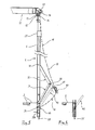
- FIG. 1 a commercial vehicle in the form of a semi-trailer. Its structure consists of an above the vehicle chassis arranged, forklift-free loading floor 2, a in FIG. 1 Not shown roof construction 15, a front wall 3, a rear wall 4 and a left and a right side cover 9.
- Each side cover 9 is composed of several the roof structure 15 supporting stanchions 5 and at least one side tarpaulin 10 together.
- the side tarp 10 is made of a flexible material, for. As a coated fabric, and extends over the length to be opened of the commercial vehicle body, preferably over the entire length of the commercial vehicle body.
- Both the stanchions 5 and the side tarp 10 extend over the height of the commercial vehicle body. They extend in particular from the height of the loading floor 2 up to the roof structure supported by the front wall 3, the rear wall 4 and the stanchions 5.
- On the reel unit 12 are two or more rollers thirteenth freely rotatably mounted, which run in a rail 14 in height of the roof structure 15. By means of the roll apparatus 12, the stanchion 5 can therefore be suspended in the rail 14 and displaced in the vehicle longitudinal direction.
- a further rail 16 is arranged at the level of the roof structure 15, in which the in the FIGS. 3, 4 and 5 dashed reproduced side tarpaulin 10 is mounted with its upper edge 17, and along which the upper edge 17 is guided during the opening and closing of the side tarpaulin 10.
- each stanchion 5 is, as far as no loading or unloading takes place, locked to the loading floor 2 of the commercial vehicle body.
- the loading floor or the side profile of the loading floor is provided with a stanchion holder 20 fastened to the outside thereof.
- Runge 5 To operate a built-in Runge 5 stanchion locking an operating handle is arranged on the stanchion. This allows by means of a mechanism designed as a lever arrangement, the positive connection and thus locking the stanchion with or on the stanchion holder 20, and vice versa, the separation of these parts from each other.
- Runge 5 In the unlocked state, the only then hanging on its reel unit 12 Runge 5 can be slightly away from the loading floor 2 and thus pivot away from the stanchion holder 20, so that then the stanchion, hanging on its reel unit 12, can be moved in the vehicle longitudinal direction to To open the side cover of the vehicle for loading and unloading large area.
- the side tarpaulin 10 is connected to each longitudinally displaceable on this side of the vehicle Runge 5 in the horizontal direction, causing it in a collapse, d. H. in a shirring of the relevant side tarpaulin 10 to the front or to the rear end of the vehicle body towards a simultaneous entrainment of the stanchions 5 comes, and vice versa in a method of stanchions 5 in the vehicle longitudinal direction to a simultaneous take away of the tarpaulin 10th
- the connecting means 25 are straps or loops fastened to the inside of the tarpaulin and which are guided at least around the front, inner and back sides of the stanchion body 6.
- each band 25 of two detachable band halves so as to be able to fully open the band, such as for replacement of a defective side panel.
- the connections 25 may be multiple over the height of the stanchion.
- the lever arrangement for fastening the stanchion to the stanchion holder essentially consists of a first toggle lever 31 and a second toggle lever 32, which are connected to one another in a pivot joint 38 with a horizontal pivot axis.
- the lever arrangement can be configured as desired.
- the first toggle lever 31 is supported with its lower end from above on the stanchion holder 20, whereas the upper end of the first toggle lever 31 is connected via the pivot joint 38 with the second toggle lever 32.
- the lower end of the toggle lever 31 can be inserted from above into a trough 34 on the stanchion holder 20 without being permanently and permanently fixed therein.
- this lower end of the toggle lever 31 is designed in the manner of a bolt which extends parallel to the pivot joint 38. The bolt is guided vertically on the stanchion body 6. As a result, a longitudinal guidance of the lower end of the toggle lever 31 in the longitudinal direction of the stanchion on the stanchion body 6 is achieved.
- the second, designed in the embodiment described here as a pressure plate 33 toggle lever 32 is pivotable about a trained at its upper end pivot joint 37 to the stanchion body 6 out, and at the same time via the aforementioned pivot joint 38 with the first toggle lever 31 coupled.
- the second toggle lever 32 covers due to its design as a flat pressure plate 33 a vertical longitudinal portion of the stanchion body 6 on the entire width to the outside.
- a tensioning lever 40 which is designed to be pivotable relative to the stanchion body 6 and which extends approximately parallel to the toggle lever 31.
- the upper end of the clamping lever 40 is coupled via a pivot joint 41 with a horizontal, extending in the vehicle longitudinal direction pivot axis with the toggle lever 32.
- this pivot joint 41 may coincide with the pivot joint 38.
- a separate arrangement of the pivot joints 41, 38 on the toggle lever 32 is preferred.
- the Fig. 3 shows that the clamping lever 40, although approximately, but not exactly parallel to the toggle lever 31 runs. Rather, with unlocked Runge ( Fig. 3 The result is that when closing the stanchion and with respect to the stanchion body 6, the lower end of the clamping lever 40 and thus the edge 48 of the tarpaulin more vertically lower than that on the Stanchion holder 20 is supported, lower end of the toggle lever 31. It therefore comes to a vertical tightening of the side tarpaulin 10.
- locked Runge Fig. 4
- clamping lever 40 and toggle 31 both perpendicular and thus parallel to Runge 5, resulting in a space-saving arrangement.
- the fastening tab 45 or the lower end of the clamping lever 40 is longitudinally guided on a guide 47 on the stanchion body 6.
- the guide 47 is formed here as a slot.
- the additional tensioning lever 40 when locking the stanchion leads to a vertical stretching of the side tarpaulin 10 as a result of pressure exerted on the lower edge of the tarpaulin 48. However, this pressure and thus a tension on the tarpaulin only and only with the locking of the stanchion 5 exerted on the stanchion holder 20. This condition is in Fig. 4 played. If, however, the stanchion is according to Fig. 3 unlocked, there is no vertical tightening of the side tarpaulins, so that they can slide during the pushing together and thus shirring and also during closing low-resistance along the roof structure of the commercial vehicle body.
- the loop 50 is preferably passed through an opening in the side tarp to the outside of the side tarpaulin and is there, without to have to remove the side tarpaulin, good by hand to pull behind the toggle lever 32 for unlocking the stanchion by hand to the outside.
- the tensioning lever 40 is composed of two partial levers 40A, 40B which are guided parallel to one another and which are arranged in the vehicle longitudinal direction in front of or behind the stanchion body 6.
- the eyelets 46 At the lower end of the partial levers 40A, 40B are the eyelets 46, to which the side tarpaulin is fastened near its lower edge 48.
- the design with two parallel partial levers 40A, 40B leads to a favorable distribution of the downward force for tensioning the side tarpaulin.
- the lower edge 48 of the tarpaulin applies, even without additional fastening means, close and preferably close to the vehicle side. Therefore, at least some of the clamping elements usually used for vertical stretching of side tarpaulins can be dispensed with.
- the lower guide 47 of the clamping levers 40A, 40B may be designed as a slot formed in the profiles of the main body 6 of the stanchions.
- a securing mechanism for locking the stanchion lock is arranged in the stanchion body 6.
- Part of the safety mechanism is a movable at the bottom of the pillar body 6, and there palpable by hand Entsperrelement 55.
- the unlocking 55 is at the level of the lower edge of the tarpaulin 48, whereby it is still easy to grip even with stretched side tarpaulin 10, so the lever assembly to release.
Landscapes
- Engineering & Computer Science (AREA)
- Mechanical Engineering (AREA)
- Chemical & Material Sciences (AREA)
- Combustion & Propulsion (AREA)
- Transportation (AREA)
- Tents Or Canopies (AREA)
- Body Structure For Vehicles (AREA)
Applications Claiming Priority (1)
| Application Number | Priority Date | Filing Date | Title |
|---|---|---|---|
| DE102013108858.9A DE102013108858A1 (de) | 2013-08-15 | 2013-08-15 | Seitenabdeckung eines Nutzfahrzeugaufbaus |
Publications (3)
| Publication Number | Publication Date |
|---|---|
| EP2842841A2 true EP2842841A2 (fr) | 2015-03-04 |
| EP2842841A3 EP2842841A3 (fr) | 2015-05-06 |
| EP2842841B1 EP2842841B1 (fr) | 2019-10-02 |
Family
ID=51357779
Family Applications (1)
| Application Number | Title | Priority Date | Filing Date |
|---|---|---|---|
| EP14181045.7A Active EP2842841B1 (fr) | 2013-08-15 | 2014-08-14 | Structure et bâchage latérale d'un véhicule utilitaire |
Country Status (2)
| Country | Link |
|---|---|
| EP (1) | EP2842841B1 (fr) |
| DE (1) | DE102013108858A1 (fr) |
Cited By (2)
| Publication number | Priority date | Publication date | Assignee | Title |
|---|---|---|---|---|
| CN108189747A (zh) * | 2018-02-02 | 2018-06-22 | 中建八局第建设有限公司 | 一种渣土车用防尘机构 |
| EP3556589A1 (fr) * | 2018-04-17 | 2019-10-23 | Schmitz Cargobull Gotha GmbH | Châssis, élément de fermeture de planification, construction de véhicule et véhicule utilitaire |
Citations (1)
| Publication number | Priority date | Publication date | Assignee | Title |
|---|---|---|---|---|
| EP2330020A1 (fr) | 2009-12-07 | 2011-06-08 | F. HESTERBERG & SÖHNE GmbH & Co. KG | Recouvrement latéral d'un châssis de véhicule utilitaire |
Family Cites Families (7)
| Publication number | Priority date | Publication date | Assignee | Title |
|---|---|---|---|---|
| CH688232A5 (de) * | 1993-08-03 | 1997-06-30 | Alusuisse Lonza Services Ag | Fahrzeug mit Pritsche und abklappbarer Bordwand. |
| DE29616344U1 (de) * | 1996-09-19 | 1996-11-14 | F. Hesterberg & Söhne GmbH & Co KG, 58256 Ennepetal | Hängerunge |
| DE10228982A1 (de) * | 2002-06-28 | 2004-01-15 | Edscha Lkw-Schiebeverdecke Gmbh | Runge |
| DE10247479B4 (de) * | 2002-10-11 | 2007-01-25 | Fahrzeugwerk Bernard Krone Gmbh | Fahrzeugaufbau für Nutzfahrzeuge |
| DE102006018608A1 (de) * | 2006-04-21 | 2007-10-25 | F. Hesterberg & Söhne Gmbh & Co. Kg | Runge für die Ladeöffnung eines Fahrzeugaufbaus |
| US7578539B1 (en) * | 2008-05-05 | 2009-08-25 | Roland Curtains Usa, Inc. | Apparatus for decreasing opening velocities of support pillars |
| DE102010000114A1 (de) * | 2010-01-19 | 2011-07-21 | TSE Trailer-System-Engineering GmbH & Co. KG, 72365 | Nutzfahrzeugaufbau |
-
2013
- 2013-08-15 DE DE102013108858.9A patent/DE102013108858A1/de not_active Withdrawn
-
2014
- 2014-08-14 EP EP14181045.7A patent/EP2842841B1/fr active Active
Patent Citations (1)
| Publication number | Priority date | Publication date | Assignee | Title |
|---|---|---|---|---|
| EP2330020A1 (fr) | 2009-12-07 | 2011-06-08 | F. HESTERBERG & SÖHNE GmbH & Co. KG | Recouvrement latéral d'un châssis de véhicule utilitaire |
Cited By (2)
| Publication number | Priority date | Publication date | Assignee | Title |
|---|---|---|---|---|
| CN108189747A (zh) * | 2018-02-02 | 2018-06-22 | 中建八局第建设有限公司 | 一种渣土车用防尘机构 |
| EP3556589A1 (fr) * | 2018-04-17 | 2019-10-23 | Schmitz Cargobull Gotha GmbH | Châssis, élément de fermeture de planification, construction de véhicule et véhicule utilitaire |
Also Published As
| Publication number | Publication date |
|---|---|
| EP2842841A3 (fr) | 2015-05-06 |
| DE102013108858A1 (de) | 2015-02-19 |
| EP2842841B1 (fr) | 2019-10-02 |
Similar Documents
| Publication | Publication Date | Title |
|---|---|---|
| EP2353904B1 (fr) | Bâche latérale déplaçable pour un camion de transport | |
| DE8625322U1 (de) | Klappverdeck für Geländewagen | |
| DE3001430C2 (de) | Kofferraumabdeckung für Kraftfahrzeuge | |
| EP3106333B1 (fr) | Carrosserie de vehicule, en particulier pour vehicules utilitaires, vehicule utilitaire comprenant une telle carrosserie et procede de fabrication | |
| DE202012104195U1 (de) | Nutzfahrzeugaufbau mit mindestens einer Seitenplane | |
| EP2330020B1 (fr) | Recouvrement latéral d'un châssis de véhicule utilitaire | |
| EP2842841B1 (fr) | Structure et bâchage latérale d'un véhicule utilitaire | |
| DE60014788T2 (de) | Faltdach für Fahrzeug | |
| CH605237A5 (en) | Flexible side walls for lorry | |
| EP2708393B1 (fr) | Caisse de véhicule pour le transport de marchandises de transport empilables ou coulables | |
| DE102015108781B4 (de) | Fahrzeugaufbau, insbesondere für Nutzfahrzeuge, Nutzfahrzeug mit einem solchen Fahrzeugaufbau und Herstellunsgverfahren | |
| DE4344592C2 (de) | Planenkonstruktion | |
| EP3587181B1 (fr) | Véhicule de transport | |
| DE102015119907A1 (de) | Spriegelkonstruktion, Aufbau für Nutzfahrzeuge, Wechselbrücke und Nutzfahrzeug mit Aufbau | |
| EP3064385B1 (fr) | Structure de vehicule dotée d'une bache coulissante | |
| DE202007014462U1 (de) | Schnell lösbare Befestigungsvorrichtung für einen Gegenstände aufnehmenden Behälter | |
| DE3425016C2 (fr) | ||
| DE19720525C2 (de) | Plane für Lastfahrzeuge | |
| EP3002143B1 (fr) | Recouvrement lateral d'un chassis de vehicule utilitaire | |
| EP3034340B1 (fr) | Structure de vehicule dotee d'une bache coulissante | |
| EP3964429A1 (fr) | Structure de bâche et véhicule utilitaire pourvu de bâche à panneaux | |
| DE202008003336U1 (de) | Befestigungsvorrichtung an einer Ladefläche eines Fahrzeuges | |
| EP3705330A1 (fr) | Structure de bâche pourvue de dispositif d'arrêt de montant coulissant | |
| DE20302749U1 (de) | System zur Sicherung von Ladung | |
| DE10108494A1 (de) | Vorrichtung zum Anziehen einer Tür oder eines Fensters an den Blendrahmen |
Legal Events
| Date | Code | Title | Description |
|---|---|---|---|
| 17P | Request for examination filed |
Effective date: 20140814 |
|
| AK | Designated contracting states |
Kind code of ref document: A2 Designated state(s): AL AT BE BG CH CY CZ DE DK EE ES FI FR GB GR HR HU IE IS IT LI LT LU LV MC MK MT NL NO PL PT RO RS SE SI SK SM TR |
|
| AX | Request for extension of the european patent |
Extension state: BA ME |
|
| PUAI | Public reference made under article 153(3) epc to a published international application that has entered the european phase |
Free format text: ORIGINAL CODE: 0009012 |
|
| PUAL | Search report despatched |
Free format text: ORIGINAL CODE: 0009013 |
|
| AK | Designated contracting states |
Kind code of ref document: A3 Designated state(s): AL AT BE BG CH CY CZ DE DK EE ES FI FR GB GR HR HU IE IS IT LI LT LU LV MC MK MT NL NO PL PT RO RS SE SI SK SM TR |
|
| AX | Request for extension of the european patent |
Extension state: BA ME |
|
| RIC1 | Information provided on ipc code assigned before grant |
Ipc: B62D 33/02 20060101AFI20150327BHEP Ipc: B60J 5/06 20060101ALN20150327BHEP |
|
| R17P | Request for examination filed (corrected) |
Effective date: 20150820 |
|
| RBV | Designated contracting states (corrected) |
Designated state(s): AL AT BE BG CH CY CZ DE DK EE ES FI FR GB GR HR HU IE IS IT LI LT LU LV MC MK MT NL NO PL PT RO RS SE SI SK SM TR |
|
| STAA | Information on the status of an ep patent application or granted ep patent |
Free format text: STATUS: EXAMINATION IS IN PROGRESS |
|
| 17Q | First examination report despatched |
Effective date: 20180910 |
|
| RIC1 | Information provided on ipc code assigned before grant |
Ipc: B62D 33/02 20060101AFI20190314BHEP Ipc: B60J 5/06 20060101ALN20190314BHEP |
|
| GRAP | Despatch of communication of intention to grant a patent |
Free format text: ORIGINAL CODE: EPIDOSNIGR1 |
|
| STAA | Information on the status of an ep patent application or granted ep patent |
Free format text: STATUS: GRANT OF PATENT IS INTENDED |
|
| INTG | Intention to grant announced |
Effective date: 20190426 |
|
| GRAS | Grant fee paid |
Free format text: ORIGINAL CODE: EPIDOSNIGR3 |
|
| GRAA | (expected) grant |
Free format text: ORIGINAL CODE: 0009210 |
|
| STAA | Information on the status of an ep patent application or granted ep patent |
Free format text: STATUS: THE PATENT HAS BEEN GRANTED |
|
| AK | Designated contracting states |
Kind code of ref document: B1 Designated state(s): AL AT BE BG CH CY CZ DE DK EE ES FI FR GB GR HR HU IE IS IT LI LT LU LV MC MK MT NL NO PL PT RO RS SE SI SK SM TR |
|
| REG | Reference to a national code |
Ref country code: GB Ref legal event code: FG4D Free format text: NOT ENGLISH |
|
| REG | Reference to a national code |
Ref country code: CH Ref legal event code: EP Ref country code: AT Ref legal event code: REF Ref document number: 1185878 Country of ref document: AT Kind code of ref document: T Effective date: 20191015 |
|
| REG | Reference to a national code |
Ref country code: DE Ref legal event code: R096 Ref document number: 502014012746 Country of ref document: DE |
|
| REG | Reference to a national code |
Ref country code: IE Ref legal event code: FG4D Free format text: LANGUAGE OF EP DOCUMENT: GERMAN |
|
| REG | Reference to a national code |
Ref country code: NL Ref legal event code: MP Effective date: 20191002 |
|
| REG | Reference to a national code |
Ref country code: LT Ref legal event code: MG4D |
|
| PG25 | Lapsed in a contracting state [announced via postgrant information from national office to epo] |
Ref country code: NO Free format text: LAPSE BECAUSE OF FAILURE TO SUBMIT A TRANSLATION OF THE DESCRIPTION OR TO PAY THE FEE WITHIN THE PRESCRIBED TIME-LIMIT Effective date: 20200102 Ref country code: GR Free format text: LAPSE BECAUSE OF FAILURE TO SUBMIT A TRANSLATION OF THE DESCRIPTION OR TO PAY THE FEE WITHIN THE PRESCRIBED TIME-LIMIT Effective date: 20200103 Ref country code: PL Free format text: LAPSE BECAUSE OF FAILURE TO SUBMIT A TRANSLATION OF THE DESCRIPTION OR TO PAY THE FEE WITHIN THE PRESCRIBED TIME-LIMIT Effective date: 20191002 Ref country code: ES Free format text: LAPSE BECAUSE OF FAILURE TO SUBMIT A TRANSLATION OF THE DESCRIPTION OR TO PAY THE FEE WITHIN THE PRESCRIBED TIME-LIMIT Effective date: 20191002 Ref country code: LT Free format text: LAPSE BECAUSE OF FAILURE TO SUBMIT A TRANSLATION OF THE DESCRIPTION OR TO PAY THE FEE WITHIN THE PRESCRIBED TIME-LIMIT Effective date: 20191002 Ref country code: SE Free format text: LAPSE BECAUSE OF FAILURE TO SUBMIT A TRANSLATION OF THE DESCRIPTION OR TO PAY THE FEE WITHIN THE PRESCRIBED TIME-LIMIT Effective date: 20191002 Ref country code: LV Free format text: LAPSE BECAUSE OF FAILURE TO SUBMIT A TRANSLATION OF THE DESCRIPTION OR TO PAY THE FEE WITHIN THE PRESCRIBED TIME-LIMIT Effective date: 20191002 Ref country code: NL Free format text: LAPSE BECAUSE OF FAILURE TO SUBMIT A TRANSLATION OF THE DESCRIPTION OR TO PAY THE FEE WITHIN THE PRESCRIBED TIME-LIMIT Effective date: 20191002 Ref country code: FI Free format text: LAPSE BECAUSE OF FAILURE TO SUBMIT A TRANSLATION OF THE DESCRIPTION OR TO PAY THE FEE WITHIN THE PRESCRIBED TIME-LIMIT Effective date: 20191002 Ref country code: BG Free format text: LAPSE BECAUSE OF FAILURE TO SUBMIT A TRANSLATION OF THE DESCRIPTION OR TO PAY THE FEE WITHIN THE PRESCRIBED TIME-LIMIT Effective date: 20200102 Ref country code: PT Free format text: LAPSE BECAUSE OF FAILURE TO SUBMIT A TRANSLATION OF THE DESCRIPTION OR TO PAY THE FEE WITHIN THE PRESCRIBED TIME-LIMIT Effective date: 20200203 |
|
| PG25 | Lapsed in a contracting state [announced via postgrant information from national office to epo] |
Ref country code: CZ Free format text: LAPSE BECAUSE OF FAILURE TO SUBMIT A TRANSLATION OF THE DESCRIPTION OR TO PAY THE FEE WITHIN THE PRESCRIBED TIME-LIMIT Effective date: 20191002 Ref country code: IS Free format text: LAPSE BECAUSE OF FAILURE TO SUBMIT A TRANSLATION OF THE DESCRIPTION OR TO PAY THE FEE WITHIN THE PRESCRIBED TIME-LIMIT Effective date: 20200224 Ref country code: HR Free format text: LAPSE BECAUSE OF FAILURE TO SUBMIT A TRANSLATION OF THE DESCRIPTION OR TO PAY THE FEE WITHIN THE PRESCRIBED TIME-LIMIT Effective date: 20191002 Ref country code: RS Free format text: LAPSE BECAUSE OF FAILURE TO SUBMIT A TRANSLATION OF THE DESCRIPTION OR TO PAY THE FEE WITHIN THE PRESCRIBED TIME-LIMIT Effective date: 20191002 |
|
| PG25 | Lapsed in a contracting state [announced via postgrant information from national office to epo] |
Ref country code: AL Free format text: LAPSE BECAUSE OF FAILURE TO SUBMIT A TRANSLATION OF THE DESCRIPTION OR TO PAY THE FEE WITHIN THE PRESCRIBED TIME-LIMIT Effective date: 20191002 |
|
| REG | Reference to a national code |
Ref country code: DE Ref legal event code: R097 Ref document number: 502014012746 Country of ref document: DE |
|
| PG2D | Information on lapse in contracting state deleted |
Ref country code: IS |
|
| PG25 | Lapsed in a contracting state [announced via postgrant information from national office to epo] |
Ref country code: DK Free format text: LAPSE BECAUSE OF FAILURE TO SUBMIT A TRANSLATION OF THE DESCRIPTION OR TO PAY THE FEE WITHIN THE PRESCRIBED TIME-LIMIT Effective date: 20191002 Ref country code: EE Free format text: LAPSE BECAUSE OF FAILURE TO SUBMIT A TRANSLATION OF THE DESCRIPTION OR TO PAY THE FEE WITHIN THE PRESCRIBED TIME-LIMIT Effective date: 20191002 Ref country code: RO Free format text: LAPSE BECAUSE OF FAILURE TO SUBMIT A TRANSLATION OF THE DESCRIPTION OR TO PAY THE FEE WITHIN THE PRESCRIBED TIME-LIMIT Effective date: 20191002 Ref country code: IS Free format text: LAPSE BECAUSE OF FAILURE TO SUBMIT A TRANSLATION OF THE DESCRIPTION OR TO PAY THE FEE WITHIN THE PRESCRIBED TIME-LIMIT Effective date: 20200202 |
|
| PLBE | No opposition filed within time limit |
Free format text: ORIGINAL CODE: 0009261 |
|
| STAA | Information on the status of an ep patent application or granted ep patent |
Free format text: STATUS: NO OPPOSITION FILED WITHIN TIME LIMIT |
|
| PG25 | Lapsed in a contracting state [announced via postgrant information from national office to epo] |
Ref country code: SK Free format text: LAPSE BECAUSE OF FAILURE TO SUBMIT A TRANSLATION OF THE DESCRIPTION OR TO PAY THE FEE WITHIN THE PRESCRIBED TIME-LIMIT Effective date: 20191002 Ref country code: IT Free format text: LAPSE BECAUSE OF FAILURE TO SUBMIT A TRANSLATION OF THE DESCRIPTION OR TO PAY THE FEE WITHIN THE PRESCRIBED TIME-LIMIT Effective date: 20191002 Ref country code: SM Free format text: LAPSE BECAUSE OF FAILURE TO SUBMIT A TRANSLATION OF THE DESCRIPTION OR TO PAY THE FEE WITHIN THE PRESCRIBED TIME-LIMIT Effective date: 20191002 |
|
| 26N | No opposition filed |
Effective date: 20200703 |
|
| PG25 | Lapsed in a contracting state [announced via postgrant information from national office to epo] |
Ref country code: SI Free format text: LAPSE BECAUSE OF FAILURE TO SUBMIT A TRANSLATION OF THE DESCRIPTION OR TO PAY THE FEE WITHIN THE PRESCRIBED TIME-LIMIT Effective date: 20191002 |
|
| PG25 | Lapsed in a contracting state [announced via postgrant information from national office to epo] |
Ref country code: MC Free format text: LAPSE BECAUSE OF FAILURE TO SUBMIT A TRANSLATION OF THE DESCRIPTION OR TO PAY THE FEE WITHIN THE PRESCRIBED TIME-LIMIT Effective date: 20191002 |
|
| REG | Reference to a national code |
Ref country code: CH Ref legal event code: PL |
|
| GBPC | Gb: european patent ceased through non-payment of renewal fee |
Effective date: 20200814 |
|
| PG25 | Lapsed in a contracting state [announced via postgrant information from national office to epo] |
Ref country code: LU Free format text: LAPSE BECAUSE OF NON-PAYMENT OF DUE FEES Effective date: 20200814 Ref country code: LI Free format text: LAPSE BECAUSE OF NON-PAYMENT OF DUE FEES Effective date: 20200831 Ref country code: CH Free format text: LAPSE BECAUSE OF NON-PAYMENT OF DUE FEES Effective date: 20200831 |
|
| REG | Reference to a national code |
Ref country code: BE Ref legal event code: MM Effective date: 20200831 |
|
| PG25 | Lapsed in a contracting state [announced via postgrant information from national office to epo] |
Ref country code: FR Free format text: LAPSE BECAUSE OF NON-PAYMENT OF DUE FEES Effective date: 20200831 |
|
| PG25 | Lapsed in a contracting state [announced via postgrant information from national office to epo] |
Ref country code: IE Free format text: LAPSE BECAUSE OF NON-PAYMENT OF DUE FEES Effective date: 20200814 Ref country code: GB Free format text: LAPSE BECAUSE OF NON-PAYMENT OF DUE FEES Effective date: 20200814 Ref country code: BE Free format text: LAPSE BECAUSE OF NON-PAYMENT OF DUE FEES Effective date: 20200831 |
|
| REG | Reference to a national code |
Ref country code: AT Ref legal event code: MM01 Ref document number: 1185878 Country of ref document: AT Kind code of ref document: T Effective date: 20200814 |
|
| PG25 | Lapsed in a contracting state [announced via postgrant information from national office to epo] |
Ref country code: AT Free format text: LAPSE BECAUSE OF NON-PAYMENT OF DUE FEES Effective date: 20200814 |
|
| REG | Reference to a national code |
Ref country code: DE Ref legal event code: R082 Ref document number: 502014012746 Country of ref document: DE Representative=s name: JANKE SCHOLL PATENTANWAELTE PARTG MBB, DE |
|
| PG25 | Lapsed in a contracting state [announced via postgrant information from national office to epo] |
Ref country code: TR Free format text: LAPSE BECAUSE OF FAILURE TO SUBMIT A TRANSLATION OF THE DESCRIPTION OR TO PAY THE FEE WITHIN THE PRESCRIBED TIME-LIMIT Effective date: 20191002 Ref country code: MT Free format text: LAPSE BECAUSE OF FAILURE TO SUBMIT A TRANSLATION OF THE DESCRIPTION OR TO PAY THE FEE WITHIN THE PRESCRIBED TIME-LIMIT Effective date: 20191002 Ref country code: CY Free format text: LAPSE BECAUSE OF FAILURE TO SUBMIT A TRANSLATION OF THE DESCRIPTION OR TO PAY THE FEE WITHIN THE PRESCRIBED TIME-LIMIT Effective date: 20191002 |
|
| PG25 | Lapsed in a contracting state [announced via postgrant information from national office to epo] |
Ref country code: MK Free format text: LAPSE BECAUSE OF FAILURE TO SUBMIT A TRANSLATION OF THE DESCRIPTION OR TO PAY THE FEE WITHIN THE PRESCRIBED TIME-LIMIT Effective date: 20191002 |
|
| PGFP | Annual fee paid to national office [announced via postgrant information from national office to epo] |
Ref country code: DE Payment date: 20240829 Year of fee payment: 11 |