EP2842631B1 - Filtrationsvorrichtung - Google Patents
Filtrationsvorrichtung Download PDFInfo
- Publication number
- EP2842631B1 EP2842631B1 EP14179857.9A EP14179857A EP2842631B1 EP 2842631 B1 EP2842631 B1 EP 2842631B1 EP 14179857 A EP14179857 A EP 14179857A EP 2842631 B1 EP2842631 B1 EP 2842631B1
- Authority
- EP
- European Patent Office
- Prior art keywords
- base
- housing body
- main housing
- rotor
- filtering device
- Prior art date
- Legal status (The legal status is an assumption and is not a legal conclusion. Google has not performed a legal analysis and makes no representation as to the accuracy of the status listed.)
- Active
Links
Images

Classifications
-
- B—PERFORMING OPERATIONS; TRANSPORTING
- B01—PHYSICAL OR CHEMICAL PROCESSES OR APPARATUS IN GENERAL
- B01D—SEPARATION
- B01D33/00—Filters with filtering elements which move during the filtering operation
- B01D33/06—Filters with filtering elements which move during the filtering operation with rotary cylindrical filtering surfaces, e.g. hollow drums
- B01D33/11—Filters with filtering elements which move during the filtering operation with rotary cylindrical filtering surfaces, e.g. hollow drums arranged for outward flow filtration
-
- B—PERFORMING OPERATIONS; TRANSPORTING
- B01—PHYSICAL OR CHEMICAL PROCESSES OR APPARATUS IN GENERAL
- B01D—SEPARATION
- B01D17/00—Separation of liquids, not provided for elsewhere, e.g. by thermal diffusion
- B01D17/02—Separation of non-miscible liquids
- B01D17/0217—Separation of non-miscible liquids by centrifugal force
-
- B—PERFORMING OPERATIONS; TRANSPORTING
- B04—CENTRIFUGAL APPARATUS OR MACHINES FOR CARRYING-OUT PHYSICAL OR CHEMICAL PROCESSES
- B04B—CENTRIFUGES
- B04B5/00—Other centrifuges
- B04B5/005—Centrifugal separators or filters for fluid circulation systems, e.g. for lubricant oil circulation systems
-
- B—PERFORMING OPERATIONS; TRANSPORTING
- B01—PHYSICAL OR CHEMICAL PROCESSES OR APPARATUS IN GENERAL
- B01D—SEPARATION
- B01D21/00—Separation of suspended solid particles from liquids by sedimentation
- B01D21/26—Separation of sediment aided by centrifugal force or centripetal force
- B01D21/262—Separation of sediment aided by centrifugal force or centripetal force by using a centrifuge
-
- B—PERFORMING OPERATIONS; TRANSPORTING
- B01—PHYSICAL OR CHEMICAL PROCESSES OR APPARATUS IN GENERAL
- B01D—SEPARATION
- B01D33/00—Filters with filtering elements which move during the filtering operation
- B01D33/80—Accessories
- B01D33/801—Driving means, shaft packing systems or the like
-
- B—PERFORMING OPERATIONS; TRANSPORTING
- B01—PHYSICAL OR CHEMICAL PROCESSES OR APPARATUS IN GENERAL
- B01D—SEPARATION
- B01D35/00—Filtering devices having features not specifically covered by groups B01D24/00 - B01D33/00, or for applications not specifically covered by groups B01D24/00 - B01D33/00; Auxiliary devices for filtration; Filter housing constructions
- B01D35/30—Filter housing constructions
-
- B—PERFORMING OPERATIONS; TRANSPORTING
- B01—PHYSICAL OR CHEMICAL PROCESSES OR APPARATUS IN GENERAL
- B01D—SEPARATION
- B01D35/00—Filtering devices having features not specifically covered by groups B01D24/00 - B01D33/00, or for applications not specifically covered by groups B01D24/00 - B01D33/00; Auxiliary devices for filtration; Filter housing constructions
- B01D35/30—Filter housing constructions
- B01D35/306—Filter mounting adapter
-
- B—PERFORMING OPERATIONS; TRANSPORTING
- B01—PHYSICAL OR CHEMICAL PROCESSES OR APPARATUS IN GENERAL
- B01D—SEPARATION
- B01D36/00—Filter circuits or combinations of filters with other separating devices
- B01D36/04—Combinations of filters with settling tanks
- B01D36/045—Combination of filters with centrifugal separation devices
-
- B—PERFORMING OPERATIONS; TRANSPORTING
- B04—CENTRIFUGAL APPARATUS OR MACHINES FOR CARRYING-OUT PHYSICAL OR CHEMICAL PROCESSES
- B04B—CENTRIFUGES
- B04B11/00—Feeding, charging, or discharging bowls
- B04B11/04—Periodical feeding or discharging; Control arrangements therefor
-
- B—PERFORMING OPERATIONS; TRANSPORTING
- B04—CENTRIFUGAL APPARATUS OR MACHINES FOR CARRYING-OUT PHYSICAL OR CHEMICAL PROCESSES
- B04B—CENTRIFUGES
- B04B7/00—Elements of centrifuges
- B04B7/02—Casings; Lids
-
- B—PERFORMING OPERATIONS; TRANSPORTING
- B04—CENTRIFUGAL APPARATUS OR MACHINES FOR CARRYING-OUT PHYSICAL OR CHEMICAL PROCESSES
- B04B—CENTRIFUGES
- B04B9/00—Drives specially designed for centrifuges; Arrangement or disposition of transmission gearing; Suspending or balancing rotary bowls
- B04B9/06—Fluid drive
-
- B—PERFORMING OPERATIONS; TRANSPORTING
- B01—PHYSICAL OR CHEMICAL PROCESSES OR APPARATUS IN GENERAL
- B01D—SEPARATION
- B01D2201/00—Details relating to filtering apparatus
- B01D2201/31—Other construction details
- B01D2201/316—Standpipes
-
- B—PERFORMING OPERATIONS; TRANSPORTING
- B04—CENTRIFUGAL APPARATUS OR MACHINES FOR CARRYING-OUT PHYSICAL OR CHEMICAL PROCESSES
- B04B—CENTRIFUGES
- B04B1/00—Centrifuges with rotary bowls provided with solid jackets for separating predominantly liquid mixtures with or without solid particles
- B04B1/20—Centrifuges with rotary bowls provided with solid jackets for separating predominantly liquid mixtures with or without solid particles discharging solid particles from the bowl by a conveying screw coaxial with the bowl axis and rotating relatively to the bowl
- B04B2001/2041—Centrifuges with rotary bowls provided with solid jackets for separating predominantly liquid mixtures with or without solid particles discharging solid particles from the bowl by a conveying screw coaxial with the bowl axis and rotating relatively to the bowl with baffles, plates, vanes or discs attached to the conveying screw
Definitions
- This invention relates to a filtration apparatus, particularly, but not exclusively, to a centrifugal filter, which term is sometimes used for a liquid-operated centrifugal separator including a self-propelled liquid-operated centrifugal separator.
- Liquid-operated centrifugal separators are already known for separating liquids of different densities or for separating particles from liquids, and have long been used in lubrication systems, particularly diesel-powered vehicle engines (marine and marine engines), as well as in other industrial separation processes.
- the operating principle of such a separator is that a housing has a rotor mounted therein for rotation at high speed about a substantially vertical axis. Liquid is provided at high pressure along the axis of rotation and flows through openings in a central tube or cavity into the rotor chamber.
- the drive fluid for the rotor is the polluted fluid that is to be cleaned.
- denser contaminating materials or particles thereof are separated by centrifugal force and retained in the rotor, usually as a crust on the rotor inner surface.
- the rotor itself is normally formed in two parts as an upper bell-shaped cover (hereinafter referred to as main housing body) and lower base. at older arrangements, for example, as described in FIG GB 2283694A , these were connected by crimp connections.
- the cover is threadedly connected to the base and can therefore be unscrewed and re-screwed during maintenance operations.
- contaminated residual particles deposited inside the rotor chamber which tend to adhere to the inner wall, but some do not adhere well or are free in the chamber, must be removed at regular intervals.
- An object of this invention is to improve the design of centrifugal separators for such purposes.
- a filter device according to claim 1 is provided.
- the base formed as a removable closure member may be connected to the main body of the housing by being inserted into an open end of the main housing body, in which case the channel is formed around its external periphery.
- the base may be connected to the main body of the housing by placing it over an open end of the main housing body, the channel being formed around the external periphery of the removable closure member.
- the removable closure is preferably sealed to the main body via corresponding O-ring seals located above and below the peripheral channel.
- This design allows greater flexibility than heretofore, by supplying fluid to the filter from the same direction from which access to the device occurs during maintenance; and it allows problems in aligning the closure relative to the liquid inlet or outlet when the closure member is removed and replaced. That is, the channel avoids mispositioning during rotation since it is no longer important where the liquid is supplied or where it exits the device as the channel allows liquid flow around the entire circumference.
- the invention has been presented in the context of a centrifugal separator, wherein the filter means in the housing is a self-propelled rotor supported by opposite pins in respective bearing assemblies provided in / on the main body and in / at the base.
- the bearing assembly provided in the main body may be mounted within an upper end of the main body which is a closed upper end so that all maintenance accesses can be made via the removable closure.
- another fluid inlet passage and / or another fluid outlet passage may be provided in an extension of the main body, which further communicates with the passage.
- the invention is not limited to the specific field of centrifugal separators, and it can be applied to a wider scope in other types of filtering devices.
- the proposed design could be used for any cartridge filtration systems, especially for mainstream oil filters and replaceable filters.
- This exemplary embodiment has the features of a self-propelled centrifugal separator, ie a centrifuge main housing body 1 connected to a base 3.
- An upper bearing group 4 is rigidly secured in a closed upper end of the housing body 1 and held there by a threaded sleeve 5.
- a rotor 2 is mounted within the enclosure provided by the housing body 1, and the upper bearing assembly 4 allows the rotation of the rotor 2 by rotatably supporting an upper pin 18 of the rotor 2.
- the lower end of the rotor 2 has a lower pin 19 in the form of a pin with an axial bore 20.
- This pin 19 is rotatably supported by a lower bearing group 6 which is threadedly attached to an insert 8 which is fixed to the base 3 and with a locking ring 7 is held positively.
- the base 3 is in the form of a removable closure element which is in the lower open end of the Centrifuge housing body 1 is inserted and sealed in this position via O-rings 9, 10 and 11.
- the rotor 2 has an axial cavity 22 with openings 24, wherein the cavity 22 communicates with the axial bore 20 in the pin 19.
- the removable base 3 has an annular channel 13 provided around its entire circumference and an inlet passage 14 leading from a position in this channel 13 to an axial position communicating with the bore 20 in the pin 19.
- the housing body 1 is provided laterally near its lower end with a liquid inlet 15 communicating with the liquid inlet passage 12. It is further provided with a liquid outlet passage 16, which in the illustrated embodiment is located above the inlet 15 and the liquid inlet passage 12.
- pressurized working fluid is supplied to the centrifuge housing body 1 at the inlet 15. From there, the working medium passes through the liquid inlet passage 12 to the channel 13 in base 3. By making the channel 13 annular, it is ensured that the working medium, regardless of the direction of rotation of the closure element 3, will flow through the base 3 from the connection passage 12 to the inlet passage 14 during assembly can.
- the base 3 is fitted so that the inlet passage 12 in the case body 1 is completely aligned with the inlet passage 14 in the base 3, so that no change of direction occurs when the working medium flows in.
- Fig. 2a For example, the base 3 is fitted so that the inlet passage 12 in the case body 1 is completely aligned with the inlet passage 14 in the base 3, so that no change of direction occurs when the working medium flows in.
- Fig. 2a For example, the base 3 is fitted so that the inlet passage 12 in the case body 1 is completely aligned with the inlet passage 14 in the base 3, so that no change of direction occurs
- the detachable base 3 is shown to be rotationally offset with respect to the main body 1 so that the inlet passage in the body 1 is not aligned with the inlet passage 14 in the base 3.
- the working fluid flows from the first inlet passage 12 the annular channel 13 and therefore partially external to the base 3 to enter the second inlet channel 14 in the base 3, before proceeding to enter the rotor 2 with the same path as before.
- the flow of the working medium is thus continued through the inlet passage 14, through the bearing group 8, 6 and into the rotor 2.
- Liquid passes up through the axial cavity 22 of the rotor 2, passes through the openings 24 and returns downwardly along the outer chamber of the rotor to exit through the nozzles 17 in the base of the rotor 2. Since these nozzles 17 are arranged tangentially, the pressure of the working medium drives the rotor 2 when it exits at the nozzles 17. With increasing angular velocity of the rotor 2 centrifugal force develops, the dirt particles from the working fluid in the rotor 2 separates. The working medium returns after leaving the rotor 2 via the outlet passage 16 to the tub.
- the base 3 is removed along with the O-rings 9, 10 and 11 and the lower assembly of bearings 6, 7 and 8 held on base 3.
- the rotor 2 can then be removed from the centrifuge in the same downward direction.
- the centrifugal separator described above is no longer limited to providing fluid to the rotor 2 through or partially through the housing body 1. This provides increased flexibility in the arrangement of the centrifugal separator in the overall design of the apparatus, and in particular allows the supply of working fluid to the rotor 2 from the same direction as the direction from which the centrifuge is serviced, allowing better access to the working medium inlet passages becomes.
Landscapes
- Chemical & Material Sciences (AREA)
- Chemical Kinetics & Catalysis (AREA)
- Physics & Mathematics (AREA)
- Thermal Sciences (AREA)
- Centrifugal Separators (AREA)
Description
- Diese Erfindung betrifft eine Filtrationsvorrichtung, und zwar insbesondere, aber nicht ausschließlich, einen Zentrifugalfilter, wobei dieser Begriff gelegentlich für einen flüssigkeitsbetriebenen Zentrifugalseparator einschließlich eines selbstangetriebenen flüssigkeitsbetriebenen Zentrifugalseparators benutzt wird.
- Flüssigkeitsbetriebene Zentrifugalseparatoren sind für das Trennen von Flüssigkeiten unterschiedlicher Dichten oder zum Trennen von Partikeln aus Flüssigkeiten bereits bekannt, und sie werden seit langem in Schmiersystemen insbesondere bei dieselbetriebenen Fahrzeugmotoren (Kfz- und Schiffsmotoren) sowie in anderen industriellen Trennprozessen eingesetzt. Das Betriebsprinzip eines derartigen Separators ist, dass ein Gehäuse einen Rotor aufweist, der darin für die Drehung mit hoher Geschwindigkeit um eine im Wesentlichen vertikale Achse gelagert ist. Flüssigkeit wird mit hohem Druck entlang der Rotationsachse bereitgestellt und strömt durch Öffnungen in einem zentralen Rohr bzw. einer axialen Aushöhlung in die Rotorkammer.
- Anschließend wird sie von tangential ausgerichteten Düsen in der Rotorbasis in das Gehäuse ausgestoßen, von wo sie in eine Wanne abfließt. In selbstangetriebenen Separatoren ist die Antriebsflüssigkeit für den Rotor die verschmutzte Flüssigkeit, die gereinigt werden soll. Beim Durchlauf der Flüssigkeit durch den Rotor werden dichtere kontaminierende Materialien oder Partikel daraus mit Zentrifugalkraft separiert und im Rotor zurückgehalten, und zwar normalerweise als Kruste auf der Rotorinnenfläche.
- Der Rotor selbst ist normalerweise in zwei Teilen als obere glockenförmige Abdeckung (im Folgenden als Hauptgehäusekörper bezeichnet) und untere Basis ausgebildet. Bei älteren Anordnungen, beispielsweise entsprechend der Beschreibung in
GB 2283694A GB 2465374A GB 2478578A - Bei einigen Gerätekonzepten ist es nunmehr wünschenswert, dass die Abdeckung, und zwar der Hauptgehäusekörper, in der Position verbleibt, während die Basis der Teil ist, der bei der Wartung abnehmbar ist. Ein Ziel dieser Erfindung ist die Verbesserung des Designs von Zentrifugalseparatoren für derartige Zwecke.
- Eine Vorrichtung gemäß dem Oberbegriff des Anspruchs 1 ist aus
US 6 621 455 B1 bekannt. - Gemäß der Erfindung wird eine Filtervorrichtung gemäß Anspruch 1 bereitgestellt. Die als abnehmbares Verschlusselement ausgebildete Basis kann mit dem Hauptkörper des Gehäuses verbunden werden, indem sie in ein offenes Ende des Hauptgehäusekörpers eingesetzt wird, wobei der Kanal in diesem Fall um dessen externen Umfang herum ausgebildet wird. Bei alternativen Ausführungsformen kann die Basis mit dem Hauptkörper des Gehäuses verbunden werden, indem sie über einem offenen Ende des Hauptgehäusekörpers angeordnet wird, wobei der Kanal um den externen Umfang des abnehmbaren Verschlusselements herum ausgebildet wird. Bei beiden Versionen ist der abnehmbare Verschluss vorzugsweise über entsprechende oberhalb und unterhalb des Umfangskanals angeordnete O-Ring-Dichtungen am Hauptgehäusekörper abgedichtet.
- Dieses Design ermöglicht größere Flexibilität als bisher, indem Flüssigkeit zum Filter aus der gleichen Richtung zugeführt wird, aus welcher bei der Wartung der Zugang zur Vorrichtung erfolgt; und es ermöglicht Probleme bei der Ausrichtung des Verschlusses relativ zum -Flüssigkeitseinlass bzw. -auslass, wenn das Verschlusselement entfernt und ersetzt wird. Das heißt, dass der Kanal die Fehlpositionierung bei der Rotation vermeidet, da es nicht mehr wichtig ist, wo die Flüssigkeit zugeführt wird oder wo sie aus der Vorrichtung austritt, da der Kanal den Flüssigkeitsstrom um den gesamten Umfang ermöglicht.
- Die Erfindung wurde in Zusammenhang mit einem Zentrifugalseparator vorgestellt, wobei die Filtermittel im Gehäuse ein selbstangetriebener Rotor sind, der durch entgegengesetzte Zapfen in entsprechenden Lagergruppen gelagert ist, die im/am Hauptgehäusekörper und in/an der Basis bereitgestellt sind. In diesem Zusammenhang kann die im/am Hauptgehäusekörper bereitgestellte Lagergruppe innerhalb eines oberen Endes des Hauptgehäusekörpers angebracht sein, welches ein geschlossenes oberes Ende ist, sodass alle Wartungszugriffe über den abnehmbaren Verschluss erfolgen können.
- Bei einigen Ausführungsformen der Erfindung können ein weiterer Flüssigkeitseinlassdurchgang und/oder ein weiterer Flüssigkeitsauslassdurchgang in einer Erweiterung des Hauptgehäusekörpers bereitgestellt sein, wobei dieser weitere Durchgang mit dem Kanal kommuniziert.
- Selbstverständlich ist die Erfindung jedoch nicht auf das spezifische Gebiet der Zentrifugalseparatoren eingeschränkt, und sie kann in einem breiteren Rahmen bei anderen Arten von Filtervorrichtungen angewandt werden. Beispielsweise könnte die vorgeschlagene Konstruktion für beliebige Kartuschen-Filtersysteme eingesetzt werden, insbesondere für Hauptstrom-Ölfilter und Wechselfilter.
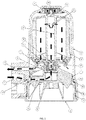
- Die Erfindung wird weiter beispielhaft mit Bezug auf die beigefügten Zeichnungen beschrieben, die Folgendes zeigen:
- Fig. 1:
- ist ein schematischer Längsschnitt einer praktischen Ausführungsform eines erfindungsgemäßen selbstangetriebenen Zentrifugalseparators; und
- Fig. 2a und 2b:
- sind schematische Querschnittsdiagramme in Höhe des Kanals im Umfang der abnehmbaren Basis der in
Fig. 1 dargestellten Ausführungsform. - Entsprechend der Darstellung in
Fig. 1 hat diese beispielhafte Ausführungsform die Merkmale eines selbstangetriebenen Zentrifugalseparators, d. h. einen mit einer Basis 3 verbundenen Zentrifugen-Hauptgehäusekörper 1. Eine obere Lagergruppe 4 ist starr in einem geschlossenen oberen Ende des Gehäusekörpers 1 befestigt und wird dort durch eine Gewindehülse 5 gehalten. Ein Rotor 2 ist innerhalb der Umhüllung angebracht, die durch den Gehäusekörper 1 bereitgestellt wird, und die obere Lagergruppe 4 ermöglicht die Rotation des Rotors 2, indem ein oberer Stift 18 des Rotors 2 drehbar gelagert wird. Das untere Ende des Rotors 2 hat einen unteren Stift 19 in Form eines Zapfens mit einer Axialbohrung 20. Dieser Zapfen 19 wird drehbar durch eine untere Lagergruppe 6 gelagert, die mittels Gewinde an einem Einsatz 8 angebracht ist, welcher an der Basis 3 befestigt und mit einem Sicherungsring 7 formschlüssig gehalten wird. Die Basis 3 hat die Form eines abnehmbaren Verschlusselements, das in das untere offene Ende des Zentrifugen-Gehäusekörpers 1 eingesetzt und in dieser Position über O-Ringe 9, 10 und 11 abgedichtet wird. Der Rotor 2 hat einen axialen Hohlraum 22 mit Öffnungen 24, wobei der Hohlraum 22 mit der Axialbohrung 20 im Zapfen 19 kommuniziert. - Die abnehmbare Basis 3 hat einen um ihren gesamten Umfang bereitgestellten ringförmigen Kanal 13 sowie einen Einlassdurchgang 14, der von einer Position in diesem Kanal 13 zu einer mit der Bohrung 20 im Zapfen 19 kommunizierenden axialen Position führt.
- Der Gehäusekörper 1 ist seitlich in der Nähe seines unteren Endes mit einem Flüssigkeitseinlass 15 ausgestattet, der mit dem Flüssigkeits-Einlassdurchgang 12 kommuniziert. Er ist weiter mit einem Flüssigkeits-Auslassdurchgang 16 ausgestattet, der bei der dargestellten Ausführungsform oberhalb des Einlasses 15 und des Flüssigkeitseinlassdurchgangs 12 angeordnet ist.
- Wenn die Basis 3 entsprechend der Darstellung am unteren Ende des Gehäusekörpers 1 positioniert ist, liegt der ringförmige Kanal 13 des Verschlusselements 3 in einer Position zwischen den beiden O-Ring-Dichtungen 9, 10, sodass er bezüglich einer Abflusskammer unterhalb des Rotors 2 abgedichtet ist. Der Gewindeeinsatz 26 zwischen der Basis 3 und dem Gehäusekörper 1 ist zwischen den O-Ring-Dichtungen 10 und 11 angeordnet.
- Im Betrieb wird mit Druck beaufschlagtes Arbeitsmedium am Einlass 15 zum Zentrifugen-Gehäusekörper 1 geführt. Von dort gelangt das Arbeitsmedium durch den Flussigkeitseinlassdurchgang 12 zum Kanal 13 in Basis 3. Dadurch, dass der Kanal 13 ringförmig ist, wird sichergestellt, dass das Arbeitsmedium ungeachtet der Drehrichtung des Verschlusselements 3 beim Zusammenbau durch die Basis 3 vom Verbindungsdurchgang 12 zum Einlassdurchgang 14 strömen kann. Dies ist in
Fig. 2a und 2b dargestellt. InFig. 2a ist die Basis 3 so eingepasst, dass der Einlassdurchgang 12 im Gehäusekörper 1 vollständig mit dem Einlassdurchgang 14 in Basis 3 ausgerichtet ist, sodass es daher bei einströmendem Arbeitsmedium zu keinem Richtungswechsel kommt. Dagegen ist inFig. 2b die abnehmbare Basis 3 so dargestellt, dass sie in Drehrichtung versetzt in Bezug auf den Hauptgehäusekörper 1 eingepasst wurde, sodass der Einlassdurchgang im Gehäusekörper 1 nicht mit dem Einlassdurchgang 14 in Basis 3 ausgerichtet ist. Bei dieser Anordnung strömt das Arbeitsmedium vom ersten Einlassdurchgang 12 durch den ringförmigen Kanal 13 und daher teilweise außen um die Basis 3, um in den zweiten Einlasskanal 14 in Basis 3 einzutreten, bevor zum Eintritt in den Rotor 2 mit dem gleichen Pfad wie zuvor fortgefahren wird. - Der Strom des Arbeitsmediums wird somit durch den Einlassdurchgang 14, durch die Lagergruppe 8, 6 und in den Rotor 2 fortgesetzt. Flüssigkeit gelangt durch den Axialhohlraum 22 des Rotors 2 nach oben, durchströmt die Öffnungen 24 und kehrt entlang der Außenkammer des Rotors nach unten zurück, um durch die Düsen 17 in der Basis des Rotors 2 auszutreten. Da diese Düsen 17 tangential angeordnet sind, treibt der Druck des Arbeitsmediums bei dessen Austritt an den Düsen 17 den Rotor 2 an. Mit zunehmender Winkelgeschwindigkeit des Rotors 2 entwickelt sich Zentrifugalkraft, die Schmutzpartikel aus dem Arbeitsmedium im Rotor 2 trennt. Das Arbeitsmedium kehrt nach dem Verlassen des Rotors 2 über den Auslassdurchgang 16 zur Wanne zurück.
- Während der Wartungseingriffe an der Zentrifuge wird die Basis 3 zusammen mit den O-Ringen 9, 10 und 11 und der unteren Anordnung von Lagerungen 6, 7 und 8, die an Basis 3 gehalten werden, abgenommen. Der Rotor 2 kann anschließend in der gleichen Abwärtsrichtung aus der Zentrifuge entfernt werden.
- Dadurch, dass das Arbeitsmedium durch die abnehmbare Basis 3 und ohne eine Drehausrichtung zu erfordern zum Rotor 2 geführt werden kann, ist der oben beschriebene Zentrifugalseparator nicht mehr darauf eingeschränkt, Flüssigkeit zum Rotor 2 durch oder teilweise durch den Gehäusekörper 1 bereitzustellen. Dies bietet eine erhöhte Flexibilität bei der Anordnung des Zentrifugalseparators im Gesamtdesign der Vorrichtung und ermöglicht insbesondere die Zufuhr von Arbeitsmedium zum Rotor 2 aus der gleichen Richtung wie der Richtung, aus der die Zentrifuge gewartet wird, wodurch ein besserer Zugang zu den Einlassdurchgängen für das Arbeitsmedium ermöglicht wird.
- Die Erfindung ist nicht auf die Details der vorstehend beschriebenen Ausführungsform beschränkt. Obwohl die Erfindung in Zusammenhang mit einem Zentrifugalseparator bzw. der Reinigung von Öl in einem Kraftfahrzeugmotor entwickelt wurde, könnte sie gleichermaßen bei einem beliebigen Bereich von Flüssigkeitssystemen eingesetzt werden, bei denen ein abnehmbarer Verschluss am Filtergehäuse bereitgestellt wird. Im Verlauf der Beschreibung und der Ansprüche dieser Spezifikation bedeuten die Begriffe "umfassen" und "enthalten" und Variationen davon "einschließlich, aber ohne diesbezügliche Einschränkung", und sie sollen den Ausschluss anderer Komponenten nicht beabsichtigen (und tun dies auch nicht). Im Verlauf der Beschreibung und der Ansprüche dieser Spezifikation umfasst die Singularform auch die Pluralform, sofern der Kontext nichts anderes erfordert. Insbesondere soll, wenn der unbestimmte Artikel verwendet wird, die Spezifikation so ausgelegt werden, dass sie Pluralität wie auch Singularität berücksichtigt, sofern der Kontext nichts anderes erfordert.
Claims (5)
- Filtervorrichtung aufweisend ein Gehäuse mit einem an einer Basis (3) lösbar angebrachten Hauptgehäusekörper (1) zur Definition eines umschlossenen Raums, wobei Filtermittel (2) bereitgestellt sind, sowie mit einem in der Basis (3) bereitgestellten Flüssigkeitseinlassdurchgang (14) zu den Filtermitteln (2) und/oder einem Flüssigkeitsauslassdurchgang von den Filtermitteln, (2) wobei die Basis (3) als abnehmbares Verschlusselement des Gehäuses dient und einen um den gesamten externen Umfang verlaufenden Kanal (13) aufweist, wobei dieser Kanal einerseits mit einem Flüssigkeitseinlass (15) und/oder einem Flüssigkeitsauslass (16) des Gehäuses kommuniziert und wobei andererseits der dazugehörige Flüssigkeitseinlassdurchgang (14) bzw. Flüssigkeitsauslassdurchgang in der als abnehmbares Verschlusselement dienenden Basis (3) bereitgestellt ist, dadurch gekennzeichnet, dass die Basis (3) in ein offenes Ende des Hauptgehäusekörpers eingesetzt und mittels eines Gewindes (26) mit dem Hauptgehäusekörper verbunden ist.
- Filtervorrichtung nach Anspruch 1, wobei die Basis (3) über entsprechende oberhalb und unterhalb des Umfangskanals angeordnete O-Ring-Dichtungen (9, 10) am Hauptgehäusekörper (1) abgedichtet ist.
- Filtervorrichtung nach einem der vorstehenden Ansprüche, wobei die Filtermittel im Gehäuse ein selbstangetriebener Rotor (2) sind, der durch entgegengesetzte Zapfen (18, 19) in entsprechenden Lagergruppen (4, 6) gelagert ist, die im/am Hauptgehäusekörper (1) und an der Basis (3) mit abnehmbarem Verschluss bereitgestellt sind.
- Filtervorrichtung nach Anspruch 3, wobei die im/am Hauptgehäusekörper (1) bereitgestellte Lagergruppe (4) innerhalb eines oberen Endes des Hauptgehäusekörpers (1), das ein geschlossenes oberes Ende ist, angebracht ist.
- Filtervorrichtung nach einem der vorstehenden Ansprüche, wobei ein weiterer Flüssigkeitseinlassdurchgang bzw. ein weiterer Flüssigkeitsauslassdurchgang in einer Erweiterung des Hauptgehäusekörpers (1) bereitgestellt ist, wobei dieser weitere Durchgang mit dem Kanal (13) kommuniziert.
Applications Claiming Priority (1)
| Application Number | Priority Date | Filing Date | Title |
|---|---|---|---|
| GB1315140.2A GB2517504B (en) | 2013-08-23 | 2013-08-23 | Filtration Apparatus |
Publications (2)
| Publication Number | Publication Date |
|---|---|
| EP2842631A1 EP2842631A1 (de) | 2015-03-04 |
| EP2842631B1 true EP2842631B1 (de) | 2018-06-06 |
Family
ID=49355863
Family Applications (1)
| Application Number | Title | Priority Date | Filing Date |
|---|---|---|---|
| EP14179857.9A Active EP2842631B1 (de) | 2013-08-23 | 2014-08-05 | Filtrationsvorrichtung |
Country Status (5)
| Country | Link |
|---|---|
| US (1) | US9474993B2 (de) |
| EP (1) | EP2842631B1 (de) |
| CN (1) | CN104415578A (de) |
| DE (1) | DE102014010433A1 (de) |
| GB (1) | GB2517504B (de) |
Families Citing this family (11)
| Publication number | Priority date | Publication date | Assignee | Title |
|---|---|---|---|---|
| WO2017053267A1 (en) | 2015-09-24 | 2017-03-30 | Cummins Filtration Ip, Inc. | Utilizing a mechanical seal between a filter media and an end cap of a rotating filter cartridge |
| CN105536345B (zh) * | 2015-12-16 | 2018-06-05 | 武汉千瑞泰环境科技有限公司 | 一种高效离心速滤机 |
| GB2563218A (en) | 2017-06-05 | 2018-12-12 | Mann & Hummel Gmbh | Rotary vessel |
| GB2563216A (en) * | 2017-06-05 | 2018-12-12 | Mann & Hummel Gmbh | Filter assembly |
| GB2563217A (en) | 2017-06-05 | 2018-12-12 | Mann & Hummel Gmbh | Rotary vessel |
| DE112018002354T5 (de) | 2017-06-20 | 2020-01-23 | Cummins Filtration Ip, Inc. | Axialstromzentrifugalabscheider |
| CN107088476B (zh) * | 2017-06-26 | 2019-02-19 | 孙亮熙 | 一种新型离心转子滤油机 |
| JP2021506576A (ja) * | 2017-12-19 | 2021-02-22 | ゼロス リミテッド | 処理装置のためのろ過器 |
| EP3801828B1 (de) | 2018-05-24 | 2025-11-26 | Cummins Filtration IP, Inc. | Verdrehsicherung für kurbelgehäuseentlüftungsfilter |
| CN109589672A (zh) * | 2019-01-22 | 2019-04-09 | 姜晓燕 | 一种检验科用成分分离装置 |
| CN110478975A (zh) * | 2019-08-01 | 2019-11-22 | 安徽其霖环境工程技术有限公司 | 一种固液分离装置 |
Citations (1)
| Publication number | Priority date | Publication date | Assignee | Title |
|---|---|---|---|---|
| US6261455B1 (en) * | 1998-10-21 | 2001-07-17 | Baldwin Filters, Inc. | Centrifuge cartridge for removing soot from oil in vehicle engine applications |
Family Cites Families (52)
| Publication number | Priority date | Publication date | Assignee | Title |
|---|---|---|---|---|
| US4400167A (en) * | 1980-04-11 | 1983-08-23 | The Glacier Metal Company Limited | Centrifugal separator |
| US4498898A (en) * | 1982-04-16 | 1985-02-12 | Ae Plc | Centrifugal separator |
| SE8401142D0 (sv) * | 1984-03-01 | 1984-03-01 | Alfa Laval Separation Ab | Utloppsanordning for en centrifugalseparator |
| GB8620468D0 (en) * | 1986-08-22 | 1986-10-01 | Atomic Energy Authority Uk | Liquid treatment apparatus |
| CH687505A5 (fr) * | 1993-01-29 | 1996-12-31 | Elp Rochat | Séparateur centrifuge pour fluides. |
| US5670042A (en) * | 1993-06-18 | 1997-09-23 | Parker Hannifin Corporation | Fuel filter assembly with replaceable element having integral cover |
| US5342519A (en) * | 1993-07-30 | 1994-08-30 | Donaldson Company, Inc. | Fluid filter cartridge with replaceable filter element |
| GB2283694B (en) | 1993-11-09 | 1998-04-22 | Glacier Metal Co Ltd | Oil cleaning assemblies for engines |
| US5637217A (en) * | 1995-01-25 | 1997-06-10 | Fleetguard, Inc. | Self-driven, cone-stack type centrifuge |
| US5762788A (en) * | 1996-08-12 | 1998-06-09 | Caterpillar Inc. | Fluid filter having a reusable filter housing and a replaceable coreless filter element |
| DE19715661A1 (de) * | 1997-04-16 | 1998-10-22 | Mann & Hummel Filter | Zentrifugenrotor |
| GB9718563D0 (en) * | 1997-09-03 | 1997-11-05 | Glacier Metal Co Ltd | Centrifugal Separation Apparatus |
| US6530872B2 (en) * | 1998-04-16 | 2003-03-11 | Filterwerk Mann & Hummel Gmbh | Free jet centrifuge rotor |
| DE19911212A1 (de) * | 1999-03-12 | 2000-09-14 | Mann & Hummel Filter | Wellenlagerung mit Lagerkalotte |
| US5960625A (en) * | 1998-08-21 | 1999-10-05 | Zdvorak, Sr.; Edward H. | Constant volume combustion turbine with plurality flow turbine wheels |
| US6579218B1 (en) * | 1998-09-25 | 2003-06-17 | Analytical Engineering, Inc. | Centrifugal filter utilizing a partial vacuum condition to effect reduced air drag on the centrifuge rotor |
| DE19934028A1 (de) * | 1998-10-28 | 2000-05-11 | Alexander Pletschacher | O¶2¶-Anreicherer |
| DE29906470U1 (de) * | 1999-04-12 | 1999-07-29 | Konzett, Alfred, Patsch | Austragelement für einen Zentrifugalabscheider |
| US6322697B1 (en) * | 1999-07-19 | 2001-11-27 | Donaldson Company, Inc. | Oil filter assembly |
| US6540914B1 (en) * | 2000-04-24 | 2003-04-01 | Vortex International, Llc | Cleanable filter with spinning screen |
| US6818046B1 (en) * | 2000-07-21 | 2004-11-16 | Charles Andrew Lowry | Liquid purifying device |
| US6428700B1 (en) * | 2000-09-06 | 2002-08-06 | Baldwin Filters, Inc. | Disposable centrifuge cartridge backed up by reusable cartridge casing in a centrifugal filter for removing soot from engine oil |
| US6364822B1 (en) * | 2000-12-07 | 2002-04-02 | Fleetguard, Inc. | Hero-turbine centrifuge with drainage enhancing baffle devices |
| WO2002055207A1 (en) * | 2001-01-13 | 2002-07-18 | Filterwerk Mann + Hummel Gmbh | Centrifugal separation apparatus |
| US6579219B2 (en) * | 2001-04-09 | 2003-06-17 | Medtronic, Inc. | Centrifuge bag and methods of use |
| US6409920B1 (en) * | 2001-06-07 | 2002-06-25 | Tsung Hui Lee | Filter device having a simplified configuration |
| SE520453C2 (sv) * | 2001-11-01 | 2003-07-15 | Alfa Laval Corp Ab | En apparat för samtidig rening av en vätska och en gas |
| SE520952C2 (sv) * | 2002-01-25 | 2003-09-16 | Alfa Laval Corp Ab | En apparat för samtidig rening av en vätska och en gas |
| DE20211556U1 (de) * | 2002-07-12 | 2003-11-20 | Hengst GmbH & Co.KG, 48147 Münster | Vorrichtung zum Abtrennen von Verunreinigungen aus dem Schmieröl einer Brennkraftmaschine |
| US6935513B2 (en) * | 2002-12-18 | 2005-08-30 | Molecular Separation Technologies, Llc | Method and apparatus for mixture separation |
| GB2401564A (en) * | 2003-05-15 | 2004-11-17 | Mann & Hummel Gmbh | Centrifugal separation apparatus and rotor |
| JP4791962B2 (ja) * | 2003-08-25 | 2011-10-12 | ポール・コーポレーション | ろ過装置及び交換可能なフィルタカートリッジ |
| ATE394169T1 (de) * | 2004-03-17 | 2008-05-15 | Hengst Gmbh & Co Kg | Freistrahlzentrifuge für die reinigung des schmieröls einer brennkraftmaschine |
| US7566294B2 (en) * | 2005-03-11 | 2009-07-28 | Cummins Filtration Ip Inc. | Spiral vane insert for a centrifuge |
| GB2425077B (en) * | 2005-04-15 | 2009-11-18 | Mann & Hummel Gmbh | Centifrugal separator and rotor therefor |
| US7674376B1 (en) * | 2005-05-27 | 2010-03-09 | Cummins Filtration Ip Inc. | Centrifuge with integral depth filter |
| US8252173B2 (en) * | 2006-04-05 | 2012-08-28 | Aquis Wasser-Luft-Systeme Gmbh, Lindau Zweigniederlassung Rebstein | Water filter cartridge system having a combined blending valve system in the candle and adjusting device in the head |
| US20080185326A1 (en) * | 2007-02-07 | 2008-08-07 | Mark Serafin | Open-end filter assembly for fluid processing system |
| US8006511B2 (en) * | 2007-06-07 | 2011-08-30 | Deka Products Limited Partnership | Water vapor distillation apparatus, method and system |
| GB0724572D0 (en) * | 2007-12-17 | 2008-01-30 | Specialist Process Technologie | A separation device |
| GB2465374A (en) * | 2008-11-14 | 2010-05-19 | Mann & Hummel Gmbh | Centrifugal separator with venturi |
| US8657913B2 (en) * | 2009-07-10 | 2014-02-25 | Alfa Laval Corporate Ab | Gas cleaning separator |
| GB2478578A (en) * | 2010-03-11 | 2011-09-14 | Mann & Hummel Gmbh | Centrifugal separator with protected bearing |
| US8007669B1 (en) * | 2010-06-24 | 2011-08-30 | Chernoff Larry J | Top loading filter canister system |
| CN103180022B (zh) * | 2010-07-21 | 2016-02-17 | 阿奎巴克技术公司 | 具有用于薄膜蒸发的涂抹器和用于移除沉积物的刮除器的蒸馏器 |
| US8945400B2 (en) * | 2010-09-30 | 2015-02-03 | Pareto Point Industries, Inc. | Method and apparatus for a parallel bypass filtration system for internal combustion engines and similar systems |
| US8469871B2 (en) * | 2010-11-19 | 2013-06-25 | Kensey Nash Corporation | Centrifuge |
| US8556794B2 (en) * | 2010-11-19 | 2013-10-15 | Kensey Nash Corporation | Centrifuge |
| DE102011076465B4 (de) * | 2011-05-25 | 2021-04-29 | Hengst Se | Zentrifugalabscheider zum Abscheiden von Ölnebel aus dem Kurbelgehäuseentlüftungsgas einer Brennkraftmaschine |
| US9022758B2 (en) * | 2012-03-23 | 2015-05-05 | Bitzer Kuehlmaschinenbau Gmbh | Floating scroll seal with retaining ring |
| US9328837B2 (en) * | 2012-10-04 | 2016-05-03 | Spx Flow, Inc. | Double seat valve with isolated vent chambers |
| US9914076B2 (en) * | 2013-07-15 | 2018-03-13 | Clarus Fluid Intelligence, Llc | Convertible filtration system |
-
2013
- 2013-08-23 GB GB1315140.2A patent/GB2517504B/en active Active
-
2014
- 2014-07-16 DE DE102014010433.8A patent/DE102014010433A1/de not_active Withdrawn
- 2014-08-05 EP EP14179857.9A patent/EP2842631B1/de active Active
- 2014-08-22 CN CN201410419051.8A patent/CN104415578A/zh active Pending
- 2014-08-22 US US14/466,376 patent/US9474993B2/en active Active
Patent Citations (1)
| Publication number | Priority date | Publication date | Assignee | Title |
|---|---|---|---|---|
| US6261455B1 (en) * | 1998-10-21 | 2001-07-17 | Baldwin Filters, Inc. | Centrifuge cartridge for removing soot from oil in vehicle engine applications |
Also Published As
| Publication number | Publication date |
|---|---|
| GB201315140D0 (en) | 2013-10-09 |
| DE102014010433A1 (de) | 2015-02-26 |
| US9474993B2 (en) | 2016-10-25 |
| US20150053603A1 (en) | 2015-02-26 |
| GB2517504A (en) | 2015-02-25 |
| EP2842631A1 (de) | 2015-03-04 |
| CN104415578A (zh) | 2015-03-18 |
| GB2517504B (en) | 2016-02-17 |
Similar Documents
| Publication | Publication Date | Title |
|---|---|---|
| EP2842631A1 (de) | Filtrationsvorrichtung | |
| DE69216341T2 (de) | Filtereinheit | |
| EP2682172B1 (de) | Fluid-vorratstank mit einer filtervorrichtung | |
| DE4140140C2 (de) | Anschraubfilter für Flüssigkeiten | |
| DE102012006025B3 (de) | Bolzengelenk für Exzenterschneckenpumpe | |
| EP2865433A2 (de) | Filterelement und Filtersystem für ein Flüssigmedium, insbesondere Dieselkraftstoff | |
| DE102014200582A1 (de) | Werkzeugaufnahme mit einem Düsenring | |
| WO2015078687A1 (de) | Filterelement und filtersystem mit nebenstromfilterung | |
| EP2808071B1 (de) | Filtereinrichtung, insbesondere für ein Kraftfahrzeug | |
| EP2112336B1 (de) | Gemeinsame Ölversorgung des VCT und der Nockenwellenlager über eine hohle Nockenwelle | |
| EP4048428B1 (de) | Abscheidevorrichtung zur abscheidung von flüssigkeit aus gas, insbesondere luft, und abscheidesystem einer maschine | |
| EP2923045B1 (de) | Ölwannen-filterkombination, ölwanne und ablassvorrichtung einer ölwannen-filterkombination | |
| DE102014110583A1 (de) | Vorrichtung zum Abtrennen von Verunreinigungen aus dem Schmieröl einer Brennkraftmaschine | |
| DE102005057710B4 (de) | Wechselölfilter mit federbetätigtem Dorn für Ablauf | |
| WO2011110628A1 (de) | Ölnebelabscheider und brennkraftmaschine mit einem ölnebelabscheider | |
| DE102012004579B3 (de) | Filtereinrichtung | |
| EP3206774A1 (de) | Filterelement für eine filtereinrichtung einer verbrennungskraftmaschine sowie filtereinrichtung für eine verbrennungskraftmaschine | |
| DE102006022981B4 (de) | Sondeneinrichtung zur Messung von Prozessgrößen | |
| DE102013106264A1 (de) | Filterelement | |
| EP2598281B1 (de) | Werkzeughalter mit einem kühlschmiermittelzuführungssystem | |
| DE102016110829A1 (de) | Reinigungseinrichtung für eine Bodenreinigungsmaschine | |
| DE102014010007A1 (de) | Filtervorrichtung | |
| EP3838372B1 (de) | Filtervorrichtung | |
| DE102011015483A1 (de) | Filtervorrichtung | |
| DE202005019664U1 (de) | Rückspülfilter |
Legal Events
| Date | Code | Title | Description |
|---|---|---|---|
| 17P | Request for examination filed |
Effective date: 20140805 |
|
| AK | Designated contracting states |
Kind code of ref document: A1 Designated state(s): AL AT BE BG CH CY CZ DE DK EE ES FI FR GB GR HR HU IE IS IT LI LT LU LV MC MK MT NL NO PL PT RO RS SE SI SK SM TR |
|
| AX | Request for extension of the european patent |
Extension state: BA ME |
|
| PUAI | Public reference made under article 153(3) epc to a published international application that has entered the european phase |
Free format text: ORIGINAL CODE: 0009012 |
|
| R17P | Request for examination filed (corrected) |
Effective date: 20150324 |
|
| RBV | Designated contracting states (corrected) |
Designated state(s): AL AT BE BG CH CY CZ DE DK EE ES FI FR GB GR HR HU IE IS IT LI LT LU LV MC MK MT NL NO PL PT RO RS SE SI SK SM TR |
|
| 17Q | First examination report despatched |
Effective date: 20170911 |
|
| GRAJ | Information related to disapproval of communication of intention to grant by the applicant or resumption of examination proceedings by the epo deleted |
Free format text: ORIGINAL CODE: EPIDOSDIGR1 |
|
| GRAP | Despatch of communication of intention to grant a patent |
Free format text: ORIGINAL CODE: EPIDOSNIGR1 |
|
| GRAS | Grant fee paid |
Free format text: ORIGINAL CODE: EPIDOSNIGR3 |
|
| INTG | Intention to grant announced |
Effective date: 20180227 |
|
| GRAA | (expected) grant |
Free format text: ORIGINAL CODE: 0009210 |
|
| RAP1 | Party data changed (applicant data changed or rights of an application transferred) |
Owner name: MANN+HUMMEL GMBH |
|
| RIN1 | Information on inventor provided before grant (corrected) |
Inventor name: MCGRAIL, GLEN Inventor name: ROUSE, ANGUS Inventor name: FOULKES, NICHOLAS Inventor name: NASH, ROBIN Inventor name: MADDEN, ALFRED Inventor name: FELL, ANTHONY W. |
|
| AK | Designated contracting states |
Kind code of ref document: B1 Designated state(s): AL AT BE BG CH CY CZ DE DK EE ES FI FR GB GR HR HU IE IS IT LI LT LU LV MC MK MT NL NO PL PT RO RS SE SI SK SM TR |
|
| REG | Reference to a national code |
Ref country code: GB Ref legal event code: FG4D Free format text: NOT ENGLISH |
|
| REG | Reference to a national code |
Ref country code: CH Ref legal event code: EP Ref country code: AT Ref legal event code: REF Ref document number: 1005456 Country of ref document: AT Kind code of ref document: T Effective date: 20180615 |
|
| REG | Reference to a national code |
Ref country code: IE Ref legal event code: FG4D Free format text: LANGUAGE OF EP DOCUMENT: GERMAN |
|
| REG | Reference to a national code |
Ref country code: DE Ref legal event code: R096 Ref document number: 502014008461 Country of ref document: DE |
|
| REG | Reference to a national code |
Ref country code: DE Ref legal event code: R081 Ref document number: 502014008461 Country of ref document: DE Owner name: MANN+HUMMEL GMBH, DE Free format text: FORMER OWNER: MANN + HUMMEL GMBH, 71636 LUDWIGSBURG, DE |
|
| REG | Reference to a national code |
Ref country code: NL Ref legal event code: MP Effective date: 20180606 |
|
| REG | Reference to a national code |
Ref country code: LT Ref legal event code: MG4D |
|
| PG25 | Lapsed in a contracting state [announced via postgrant information from national office to epo] |
Ref country code: CY Free format text: LAPSE BECAUSE OF FAILURE TO SUBMIT A TRANSLATION OF THE DESCRIPTION OR TO PAY THE FEE WITHIN THE PRESCRIBED TIME-LIMIT Effective date: 20180606 Ref country code: SE Free format text: LAPSE BECAUSE OF FAILURE TO SUBMIT A TRANSLATION OF THE DESCRIPTION OR TO PAY THE FEE WITHIN THE PRESCRIBED TIME-LIMIT Effective date: 20180606 Ref country code: LT Free format text: LAPSE BECAUSE OF FAILURE TO SUBMIT A TRANSLATION OF THE DESCRIPTION OR TO PAY THE FEE WITHIN THE PRESCRIBED TIME-LIMIT Effective date: 20180606 Ref country code: ES Free format text: LAPSE BECAUSE OF FAILURE TO SUBMIT A TRANSLATION OF THE DESCRIPTION OR TO PAY THE FEE WITHIN THE PRESCRIBED TIME-LIMIT Effective date: 20180606 Ref country code: NO Free format text: LAPSE BECAUSE OF FAILURE TO SUBMIT A TRANSLATION OF THE DESCRIPTION OR TO PAY THE FEE WITHIN THE PRESCRIBED TIME-LIMIT Effective date: 20180906 Ref country code: FI Free format text: LAPSE BECAUSE OF FAILURE TO SUBMIT A TRANSLATION OF THE DESCRIPTION OR TO PAY THE FEE WITHIN THE PRESCRIBED TIME-LIMIT Effective date: 20180606 Ref country code: BG Free format text: LAPSE BECAUSE OF FAILURE TO SUBMIT A TRANSLATION OF THE DESCRIPTION OR TO PAY THE FEE WITHIN THE PRESCRIBED TIME-LIMIT Effective date: 20180906 |
|
| PG25 | Lapsed in a contracting state [announced via postgrant information from national office to epo] |
Ref country code: HR Free format text: LAPSE BECAUSE OF FAILURE TO SUBMIT A TRANSLATION OF THE DESCRIPTION OR TO PAY THE FEE WITHIN THE PRESCRIBED TIME-LIMIT Effective date: 20180606 Ref country code: RS Free format text: LAPSE BECAUSE OF FAILURE TO SUBMIT A TRANSLATION OF THE DESCRIPTION OR TO PAY THE FEE WITHIN THE PRESCRIBED TIME-LIMIT Effective date: 20180606 Ref country code: LV Free format text: LAPSE BECAUSE OF FAILURE TO SUBMIT A TRANSLATION OF THE DESCRIPTION OR TO PAY THE FEE WITHIN THE PRESCRIBED TIME-LIMIT Effective date: 20180606 Ref country code: GR Free format text: LAPSE BECAUSE OF FAILURE TO SUBMIT A TRANSLATION OF THE DESCRIPTION OR TO PAY THE FEE WITHIN THE PRESCRIBED TIME-LIMIT Effective date: 20180907 |
|
| PG25 | Lapsed in a contracting state [announced via postgrant information from national office to epo] |
Ref country code: NL Free format text: LAPSE BECAUSE OF FAILURE TO SUBMIT A TRANSLATION OF THE DESCRIPTION OR TO PAY THE FEE WITHIN THE PRESCRIBED TIME-LIMIT Effective date: 20180606 |
|
| PG25 | Lapsed in a contracting state [announced via postgrant information from national office to epo] |
Ref country code: SK Free format text: LAPSE BECAUSE OF FAILURE TO SUBMIT A TRANSLATION OF THE DESCRIPTION OR TO PAY THE FEE WITHIN THE PRESCRIBED TIME-LIMIT Effective date: 20180606 Ref country code: EE Free format text: LAPSE BECAUSE OF FAILURE TO SUBMIT A TRANSLATION OF THE DESCRIPTION OR TO PAY THE FEE WITHIN THE PRESCRIBED TIME-LIMIT Effective date: 20180606 Ref country code: IS Free format text: LAPSE BECAUSE OF FAILURE TO SUBMIT A TRANSLATION OF THE DESCRIPTION OR TO PAY THE FEE WITHIN THE PRESCRIBED TIME-LIMIT Effective date: 20181006 Ref country code: PL Free format text: LAPSE BECAUSE OF FAILURE TO SUBMIT A TRANSLATION OF THE DESCRIPTION OR TO PAY THE FEE WITHIN THE PRESCRIBED TIME-LIMIT Effective date: 20180606 Ref country code: CZ Free format text: LAPSE BECAUSE OF FAILURE TO SUBMIT A TRANSLATION OF THE DESCRIPTION OR TO PAY THE FEE WITHIN THE PRESCRIBED TIME-LIMIT Effective date: 20180606 Ref country code: RO Free format text: LAPSE BECAUSE OF FAILURE TO SUBMIT A TRANSLATION OF THE DESCRIPTION OR TO PAY THE FEE WITHIN THE PRESCRIBED TIME-LIMIT Effective date: 20180606 |
|
| PG25 | Lapsed in a contracting state [announced via postgrant information from national office to epo] |
Ref country code: IT Free format text: LAPSE BECAUSE OF FAILURE TO SUBMIT A TRANSLATION OF THE DESCRIPTION OR TO PAY THE FEE WITHIN THE PRESCRIBED TIME-LIMIT Effective date: 20180606 Ref country code: SM Free format text: LAPSE BECAUSE OF FAILURE TO SUBMIT A TRANSLATION OF THE DESCRIPTION OR TO PAY THE FEE WITHIN THE PRESCRIBED TIME-LIMIT Effective date: 20180606 |
|
| REG | Reference to a national code |
Ref country code: DE Ref legal event code: R097 Ref document number: 502014008461 Country of ref document: DE |
|
| PG25 | Lapsed in a contracting state [announced via postgrant information from national office to epo] |
Ref country code: MC Free format text: LAPSE BECAUSE OF FAILURE TO SUBMIT A TRANSLATION OF THE DESCRIPTION OR TO PAY THE FEE WITHIN THE PRESCRIBED TIME-LIMIT Effective date: 20180606 |
|
| REG | Reference to a national code |
Ref country code: CH Ref legal event code: PL |
|
| PLBE | No opposition filed within time limit |
Free format text: ORIGINAL CODE: 0009261 |
|
| STAA | Information on the status of an ep patent application or granted ep patent |
Free format text: STATUS: NO OPPOSITION FILED WITHIN TIME LIMIT |
|
| PG25 | Lapsed in a contracting state [announced via postgrant information from national office to epo] |
Ref country code: LU Free format text: LAPSE BECAUSE OF NON-PAYMENT OF DUE FEES Effective date: 20180805 Ref country code: LI Free format text: LAPSE BECAUSE OF NON-PAYMENT OF DUE FEES Effective date: 20180831 Ref country code: CH Free format text: LAPSE BECAUSE OF NON-PAYMENT OF DUE FEES Effective date: 20180831 |
|
| REG | Reference to a national code |
Ref country code: BE Ref legal event code: MM Effective date: 20180831 |
|
| 26N | No opposition filed |
Effective date: 20190307 |
|
| GBPC | Gb: european patent ceased through non-payment of renewal fee |
Effective date: 20180906 |
|
| REG | Reference to a national code |
Ref country code: IE Ref legal event code: MM4A |
|
| PG25 | Lapsed in a contracting state [announced via postgrant information from national office to epo] |
Ref country code: DK Free format text: LAPSE BECAUSE OF FAILURE TO SUBMIT A TRANSLATION OF THE DESCRIPTION OR TO PAY THE FEE WITHIN THE PRESCRIBED TIME-LIMIT Effective date: 20180606 Ref country code: SI Free format text: LAPSE BECAUSE OF FAILURE TO SUBMIT A TRANSLATION OF THE DESCRIPTION OR TO PAY THE FEE WITHIN THE PRESCRIBED TIME-LIMIT Effective date: 20180606 |
|
| PG25 | Lapsed in a contracting state [announced via postgrant information from national office to epo] |
Ref country code: IE Free format text: LAPSE BECAUSE OF NON-PAYMENT OF DUE FEES Effective date: 20180805 |
|
| PG25 | Lapsed in a contracting state [announced via postgrant information from national office to epo] |
Ref country code: FR Free format text: LAPSE BECAUSE OF NON-PAYMENT OF DUE FEES Effective date: 20180806 Ref country code: BE Free format text: LAPSE BECAUSE OF NON-PAYMENT OF DUE FEES Effective date: 20180831 |
|
| PG25 | Lapsed in a contracting state [announced via postgrant information from national office to epo] |
Ref country code: GB Free format text: LAPSE BECAUSE OF NON-PAYMENT OF DUE FEES Effective date: 20180906 |
|
| PG25 | Lapsed in a contracting state [announced via postgrant information from national office to epo] |
Ref country code: AL Free format text: LAPSE BECAUSE OF FAILURE TO SUBMIT A TRANSLATION OF THE DESCRIPTION OR TO PAY THE FEE WITHIN THE PRESCRIBED TIME-LIMIT Effective date: 20180606 |
|
| PG25 | Lapsed in a contracting state [announced via postgrant information from national office to epo] |
Ref country code: MT Free format text: LAPSE BECAUSE OF FAILURE TO SUBMIT A TRANSLATION OF THE DESCRIPTION OR TO PAY THE FEE WITHIN THE PRESCRIBED TIME-LIMIT Effective date: 20180606 |
|
| PG25 | Lapsed in a contracting state [announced via postgrant information from national office to epo] |
Ref country code: TR Free format text: LAPSE BECAUSE OF FAILURE TO SUBMIT A TRANSLATION OF THE DESCRIPTION OR TO PAY THE FEE WITHIN THE PRESCRIBED TIME-LIMIT Effective date: 20180606 |
|
| PG25 | Lapsed in a contracting state [announced via postgrant information from national office to epo] |
Ref country code: PT Free format text: LAPSE BECAUSE OF FAILURE TO SUBMIT A TRANSLATION OF THE DESCRIPTION OR TO PAY THE FEE WITHIN THE PRESCRIBED TIME-LIMIT Effective date: 20180606 Ref country code: HU Free format text: LAPSE BECAUSE OF FAILURE TO SUBMIT A TRANSLATION OF THE DESCRIPTION OR TO PAY THE FEE WITHIN THE PRESCRIBED TIME-LIMIT; INVALID AB INITIO Effective date: 20140805 |
|
| PG25 | Lapsed in a contracting state [announced via postgrant information from national office to epo] |
Ref country code: MK Free format text: LAPSE BECAUSE OF NON-PAYMENT OF DUE FEES Effective date: 20180606 |
|
| REG | Reference to a national code |
Ref country code: AT Ref legal event code: MM01 Ref document number: 1005456 Country of ref document: AT Kind code of ref document: T Effective date: 20190805 |
|
| PG25 | Lapsed in a contracting state [announced via postgrant information from national office to epo] |
Ref country code: AT Free format text: LAPSE BECAUSE OF NON-PAYMENT OF DUE FEES Effective date: 20190805 |
|
| P01 | Opt-out of the competence of the unified patent court (upc) registered |
Effective date: 20230803 |
|
| PGFP | Annual fee paid to national office [announced via postgrant information from national office to epo] |
Ref country code: DE Payment date: 20250820 Year of fee payment: 12 |