EP2842007B1 - Verfahren zur bearbeitung der abströmkante einer turbinenmotorschaufel - Google Patents
Verfahren zur bearbeitung der abströmkante einer turbinenmotorschaufel Download PDFInfo
- Publication number
- EP2842007B1 EP2842007B1 EP13723849.9A EP13723849A EP2842007B1 EP 2842007 B1 EP2842007 B1 EP 2842007B1 EP 13723849 A EP13723849 A EP 13723849A EP 2842007 B1 EP2842007 B1 EP 2842007B1
- Authority
- EP
- European Patent Office
- Prior art keywords
- machining
- points
- blade
- face
- grids
- Prior art date
- Legal status (The legal status is an assumption and is not a legal conclusion. Google has not performed a legal analysis and makes no representation as to the accuracy of the status listed.)
- Active
Links
Images

Classifications
-
- G—PHYSICS
- G05—CONTROLLING; REGULATING
- G05B—CONTROL OR REGULATING SYSTEMS IN GENERAL; FUNCTIONAL ELEMENTS OF SUCH SYSTEMS; MONITORING OR TESTING ARRANGEMENTS FOR SUCH SYSTEMS OR ELEMENTS
- G05B19/00—Programme-control systems
- G05B19/02—Programme-control systems electric
- G05B19/18—Numerical control [NC], i.e. automatically operating machines, in particular machine tools, e.g. in a manufacturing environment, so as to execute positioning, movement or co-ordinated operations by means of programme data in numerical form
- G05B19/4097—Numerical control [NC], i.e. automatically operating machines, in particular machine tools, e.g. in a manufacturing environment, so as to execute positioning, movement or co-ordinated operations by means of programme data in numerical form characterised by using design data to control NC machines, e.g. CAD/CAM
-
- B—PERFORMING OPERATIONS; TRANSPORTING
- B23—MACHINE TOOLS; METAL-WORKING NOT OTHERWISE PROVIDED FOR
- B23C—MILLING
- B23C3/00—Milling particular work; Special milling operations; Machines therefor
- B23C3/16—Working surfaces curved in two directions
- B23C3/18—Working surfaces curved in two directions for shaping screw-propellers, turbine blades, or impellers
-
- G—PHYSICS
- G05—CONTROLLING; REGULATING
- G05B—CONTROL OR REGULATING SYSTEMS IN GENERAL; FUNCTIONAL ELEMENTS OF SUCH SYSTEMS; MONITORING OR TESTING ARRANGEMENTS FOR SUCH SYSTEMS OR ELEMENTS
- G05B19/00—Programme-control systems
- G05B19/02—Programme-control systems electric
- G05B19/18—Numerical control [NC], i.e. automatically operating machines, in particular machine tools, e.g. in a manufacturing environment, so as to execute positioning, movement or co-ordinated operations by means of programme data in numerical form
- G05B19/4097—Numerical control [NC], i.e. automatically operating machines, in particular machine tools, e.g. in a manufacturing environment, so as to execute positioning, movement or co-ordinated operations by means of programme data in numerical form characterised by using design data to control NC machines, e.g. CAD/CAM
- G05B19/4099—Surface or curve machining, making 3D objects, e.g. desktop manufacturing
-
- G—PHYSICS
- G06—COMPUTING OR CALCULATING; COUNTING
- G06F—ELECTRIC DIGITAL DATA PROCESSING
- G06F30/00—Computer-aided design [CAD]
-
- B—PERFORMING OPERATIONS; TRANSPORTING
- B23—MACHINE TOOLS; METAL-WORKING NOT OTHERWISE PROVIDED FOR
- B23C—MILLING
- B23C2215/00—Details of workpieces
- B23C2215/44—Turbine blades
-
- B—PERFORMING OPERATIONS; TRANSPORTING
- B23—MACHINE TOOLS; METAL-WORKING NOT OTHERWISE PROVIDED FOR
- B23P—METAL-WORKING NOT OTHERWISE PROVIDED FOR; COMBINED OPERATIONS; UNIVERSAL MACHINE TOOLS
- B23P15/00—Making specific metal objects by operations not covered by a single other subclass or a group in this subclass
- B23P15/02—Making specific metal objects by operations not covered by a single other subclass or a group in this subclass turbine or like blades from one piece
-
- G—PHYSICS
- G05—CONTROLLING; REGULATING
- G05B—CONTROL OR REGULATING SYSTEMS IN GENERAL; FUNCTIONAL ELEMENTS OF SUCH SYSTEMS; MONITORING OR TESTING ARRANGEMENTS FOR SUCH SYSTEMS OR ELEMENTS
- G05B2219/00—Program-control systems
- G05B2219/30—Nc systems
- G05B2219/35—Nc in input of data, input till input file format
- G05B2219/35082—Product, feature based modeling, geometric and engineering info
-
- G—PHYSICS
- G05—CONTROLLING; REGULATING
- G05B—CONTROL OR REGULATING SYSTEMS IN GENERAL; FUNCTIONAL ELEMENTS OF SUCH SYSTEMS; MONITORING OR TESTING ARRANGEMENTS FOR SUCH SYSTEMS OR ELEMENTS
- G05B2219/00—Program-control systems
- G05B2219/30—Nc systems
- G05B2219/35—Nc in input of data, input till input file format
- G05B2219/35128—Propeller blade
-
- G—PHYSICS
- G05—CONTROLLING; REGULATING
- G05B—CONTROL OR REGULATING SYSTEMS IN GENERAL; FUNCTIONAL ELEMENTS OF SUCH SYSTEMS; MONITORING OR TESTING ARRANGEMENTS FOR SUCH SYSTEMS OR ELEMENTS
- G05B2219/00—Program-control systems
- G05B2219/30—Nc systems
- G05B2219/37—Measurements
- G05B2219/37355—Cutting, milling, machining force
-
- G—PHYSICS
- G05—CONTROLLING; REGULATING
- G05B—CONTROL OR REGULATING SYSTEMS IN GENERAL; FUNCTIONAL ELEMENTS OF SUCH SYSTEMS; MONITORING OR TESTING ARRANGEMENTS FOR SUCH SYSTEMS OR ELEMENTS
- G05B2219/00—Program-control systems
- G05B2219/30—Nc systems
- G05B2219/45—Nc applications
- G05B2219/45147—Machining blade, airfoil
Definitions
- the present invention relates to the manufacture of turbomachine blades and more particularly to the field of finishing machining of such parts, for example from the foundry.
- the blades mentioned above are generally manufactured by casting and casting of metal in a mold according to the so-called lost wax technique which makes it possible to obtain directly the desired shape of the blade without going through the implementation of steps of machining to reach the finished part.
- foundry techniques have reached their limits as to the fineness of the trailing edges. Additional machining is necessary.
- the document FR-A1-2 913 901 discloses a method of manufacturing a turbomachine blade according to the state of the art.
- the Applicant has set itself the goal of developing a method for manufacturing turbomachine blades whose fineness of the trailing edge meets the current requirements to improve their aerodynamic performance.
- the method of the invention allows finishing operations on a numerically controlled machine tool ensuring high precision machining and a profile satisfying the aerodynamic constraints.
- the machining is said to be adaptive because the trajectory of the machining tool adapts to the geometry of the part being machined.
- the extra thickness to be machined is provided on the upper surface, on the lower surface and / or on the rope.
- a first thickness is eliminated on the extrados which constitutes the first face.
- the rope of the blade is reduced along the trailing edge to reach the profile of the trailing edge of the desired thickness.
- the number of probed points is at least three. They are distributed between the two platforms for a distributor sector or between the platform of the foot and the top of the blade for a moving blade they are arranged parallel to the trailing edge.
- the vertices of the machining tiles comprise the probed points and points whose position is deduced by translation along the rope passing through the probed points.
- the machining is preferably performed by rolling milling, that is to say that the material is removed by the cutting peripheral wall of a cylindrical tool and not by the distal end thereof.
- machining means are within the scope of the process of the invention.
- it may be an adaptive polishing by tape using a polishing machine or polishing robot.
- It may be an adaptive machining by grinding or grinding. It may still be machining by robotic milling and not by machine tool.
- the invention covers any process and tool for the removal of adaptive material.
- the method comprises mounting the blading on a removable support and mounting the removable support on a numerically controlled machine tool with a machining trihedron, machining being performed with removal of material according to a component of the 3 axes of the machining trihedron.
- the blade being a turbine blade
- the blade is fixed on the removable support being clamped between a removable jaw and a fixed jaw so as to form a rigid assembly.
- the fixed jaw is shaped to the theoretical profile of a face of the blade, preferably its upper surface, while leaving the trailing edge free to machine.
- the workpiece is clamped over the largest possible area in order to reduce vibrations while maintaining accessibility on the one hand to the probe for measurements and, on the other hand, tools for machining.
- the removable support is arranged for an isostatic mounting of the sector in the removable support.
- the assembly is isostatic because it blocks the six degrees of freedom of the room (3 translations and 3 rotations). It takes the same points of support as those used for the control operation after machining.
- the removable support comprises means for damping the vibrations produced during machining.
- the machining of each of the vanes of the distributor sector comprises a prior step of resetting the blade to the best of the machining trihedron on the machine tool.
- the present invention also relates to the removable support for the implementation of the method, the blade being a turbine blade.
- the machining support of a mobile turbine engine blade comprising a base arranged for fixing the support to the plate of a numerically controlled machine tool and a means for fixing the blade on the base, is characterized by the fact that that the fixing means comprises a fixed jaw secured to the base and a free jaw, the fixed jaw having a bearing surface adapted to receive the blade of said blade and which is shaped to the theoretical profile of said blade.
- the present invention also relates to the support of a turbomachine distributor sector.
- the machining support of a turbine engine valve sector obtained by metal casting with a plurality of integral blades at one end of an inner platform and at the other end of an outer platform, comprising a base with a face plane arranged for fixing the support to the plate of a numerically controlled machine tool and a fixing means of the distributor sector on the base, is characterized in that the fixing means is arranged so that the zones of the edges of leakage of the blades that are to be machined are oriented perpendicularly to said plane face.
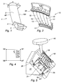
- the figure 1 shows a blade 1 of low pressure turbine seen from the side of its extrados. As it is a moving blade, it is individual and comprises a foot 3 by which it is mounted on a turbine rotor, a platform 4 between the foot 3 and the blade 2. A second platform 5 is formed at the top dawn 1. The blade 2 extends between the two platforms also along its rope between the leading edge BA and the trailing edge BF finer. The axis of rotation of the turbine rotor on which the blade is mounted is parallel to the axis of the blade root.
- the figure 2 shows a sector 10 of low pressure turbine valve, monobloc, obtained by casting metal.
- This sector comprises a plurality of blades 11 to 15 disposed radially disc sector between an inner platform 17 and an outer platform 18 both in an arc.
- Such a low pressure distributor sector 10, such as low pressure mobile blades is manufactured according to the lost wax casting technique known per se. Despite the precision obtained, this technique does not achieve the small thicknesses required at the trailing edges. Machining is therefore necessary.
- the invention provides a method for achieving such a finish, taking into account the deformations of the blade.
- the process applied to the finishing of blades 11 to 16 of a six-blade monobloc dispenser sector is described.
- This is first mounted on a removable support 20 as seen on the figure 3 .
- It is an isostatic assembly according to the three axes of a rectangle trihedron, in particular of the reference trihedron of the sector with a maintenance in translation along the three axes of the reference trihedron, by the flange 21 arranged on the side of the platform 18 at the center of the latter and which ensures the wedging in the three directions of the trihedron, and three rotational locking supports by the flanges 22, 23 at the ends of the inner platform 17 and the support 24 in the center not visible on the figure 3 .
- the assembly further comprises two vibration damping stirrups 25 and 26 disposed on either side of the flange 21.
- the angle of the plane of the sector is chosen so as to take account of that of the plane of the trailing edge zone with respect to this same plane. It is preferable that the machined surfaces of the BF are parallel to the axis of the machining tool such as a spindle. In the case of a five-axis numerical control machine, for example, this makes it possible to avoid positioning errors of the rotary axes (that is to say the 4th and 5th axes) of the machine.
- the support 20 is itself mounted on the plate 30 of the numerically controlled machine, not shown, via a base 31.
- the acquisition by probing by means of a suitable apparatus, of the position of a certain number of points on the blade and appropriate software, for example using the method of least squares, can calculate the corrections to be made to the reference trihedron of the assembly on the machining machine.
- This correction is made using 3 rotations around the X, Y, Z axes and a translation of the origin in the X, Y, Z directions (linear axes of the machine).
- the machining trihedron coincides with the main axes of the blade, 11 to 16 respectively, to be machined.
- the definition of the trihedron is related to the configuration of the machine as well as the possibility of palpating along 3 axes (the axes of rotation being deactivated).
- the positioning of the machined area of the blade parallel to the axis of the spindle induces that the axis X is the radial axis of the blade relative to the motor axis, the axis Z the axis of rotation of the plate , perpendicular to the plane of the plate, the Y axis completing the direct trihedron.
- the XY plane consists of the bearing face of the plate. It should be noted that the setting of the machining trihedron must be made for each of the blades of the distributor sector.
- It comprises the acquisition, by probing by means of a suitable probing apparatus with or without contact, of the position of a certain number of points along the trailing edge BF of the blade to be machined. These points are those defined on the theoretical 3D model of the blade in the CAD / CAM software.
- the reference mark is that of the machining trihedron.
- the number of points is preferably at least three.
- a plurality of induced points is defined.
- the set of points of contact tools / part defining the machining of the intrados and extrados must be contained in tiles, so we add the point N1 and the point N7 then the points N8 to N14. These are at the intersection of the rope passing through the probed points and the trailing edge.
- the points N1 and N7 which are too close to the platform to be palpated are obtained by translation of the adjacent points N2 and N6.
- the points N1 to N14 thus delimit the tops of machining tiles, C1 to C6.
- the value of the delta (N) deviations between the measured or induced position and the position on the theoretical model is calculated. Due to the calibration of the reference axes, this difference is measured along the main axis X.
- the quantity of material to be removed is defined on the one hand by the position of the contact of the tool in the tile and the value of the delta (N) deviations measured on each vertex of the tile concerned.
- the method of determining the amount of material to be removed by machining is described more precisely with reference to the example of figure 4 .
- the tiles are four-sided polygons, but they could have a number of different sides.
- Each point P is defined with respect to the vertices or nodes of the tile in which it is located by means of four coefficients, called weighting coefficients CPi (where i is the reference number of the node in question).
- Each weighting coefficient corresponds to the weight to be assigned to the corresponding node so that the point P is the center of gravity of these four knots. In other words, the closer the point P is to a node, the higher the coefficient assigned to this node, and conversely, the most distant nodes are assigned a low coefficient.
- these weighting coefficients are reduced proportionally to each other so that their sum is equal to 1.
- the four coefficients are equal to 0, 25; if it is close to one of the nodes, as we see on the figure 4 , the coefficient CP1 will be equal to 0.5 while the other three will be respectively equal to 0.35 for CP2, 0.10 for CP7 and 0.05 for CP8.
- the file constituted by the weightings of the points P to be scanned by the machining tool and by the corresponding orientations of the axis of the tool is then converted into a format understandable by the numerically controlled machine and loaded into its software.
- the next step is to define a delta positioning gap for all points of contact between the part and the tool during finishing machining.
- the calculation of this delta takes into account the weighting coefficients of the point P calculated previously and the delta (Ni) deviations of the nodes of the cell in which is the point P.
- the delta with the point P that is to say the correction to be made to the point P of the surface of the blade, is defined as being equal to the sum of the values obtained by multiplying each delta of a node by the weighting coefficient associated with it.
- delta (P) is equal to CP1 * delta (N1) + CP2 * delta (N2) + CP7 * delta (N7) + CP8 * delta (N8).
- delta P ⁇ CPi * delta Or ' for i corresponding to l ' index of the vertices of the d ' machining .
- This delta deviation (P) which extends along the X axis of the machining trihedron at the point P, determines the component of the correction to be applied to the Cartesian coordinates given to the program which controls the positioning of the tool during the process. finishing machining. In this case, the correction is made along the X axis alone.
- the machining is thus preferably carried out by a 5-axis numerical control machine tool for which the position of the tool is at all times corrected for the value resulting from the deltas of the nodes of the considered tile and the weighting coefficients of the point where is said tool.
- the machining is performed by rolling milling; that is to say by the cutting peripheral wall of the strawberry.
- the thickness removed during rough machining is of the order of a few tenths of mm or even a few mm (depending on the foundry allowance).
- the thickness removed during the finishing machining is of the order of a few hundredths of a millimeter.
- the value of the correction is a few tenths of a millimeter.
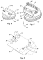
- the Figures 6 and 7 show the mounting of a blade on a mobile support 50.
- the support comprises a fixed jaw 51 whose surface 51a of contact with the moving blade is shaped to receive the upper surface of the movable blade.
- the figure 6 shows the fixed jaw only 51. It is fixed on the plate 30 and has a determined inclination. This inclination is chosen so as to allow the orientation of the machining tool in a direction such as that of the axis parallel to the axis of the spindle.
- the figure 7 shows the moving blade held between the jaw 51 and a removable jaw 52 so as to leave free the region of the trailing edge of the blade.
- the different positions of the probe S with its sphere in contact with the surface of the trailing edge zone are also shown.
- the assembly allows the probe to be positioned in each of the points whose position is to be measured.
- This arrangement allows the tool to machine rolling both sides, intrados and extrados of the blade and the rope.
- the two jaws are tightened by the screws 53.
- the clamping movement of the movable jaw against the fixed jaw is ensured by guiding along guide pins 54.
- the screws allow sufficient clamping to reduce the deformation of the blade.
- the fixed jaw 51 comprises a stop 55 for the platform of the blade root to wedge the blade in axial position.
- Machining is carried out in the same manner as described above for a distributor sector blade.
- the figure 8 shows the support 20 for dispenser sector without the coin.
- the elements of the isostatic fixation are seen with on one side the fastening flange 21 for immobilization in the three directions.
- On the other side we see the three supports for immobilization in rotation around the three axes.
- Vibration-damping stirrups 25 and 26 are arranged on either side of the flange 21. These stirrups are fixed by screws to the base and comprise bearing pads bearing against the faces of the platform. preventing the platform from vibrating.
Landscapes
- Engineering & Computer Science (AREA)
- Manufacturing & Machinery (AREA)
- Physics & Mathematics (AREA)
- General Physics & Mathematics (AREA)
- Human Computer Interaction (AREA)
- Automation & Control Theory (AREA)
- Theoretical Computer Science (AREA)
- Mechanical Engineering (AREA)
- Evolutionary Computation (AREA)
- Geometry (AREA)
- General Engineering & Computer Science (AREA)
- Computer Hardware Design (AREA)
- Turbine Rotor Nozzle Sealing (AREA)
- Architecture (AREA)
- Software Systems (AREA)
- Milling Processes (AREA)
Claims (13)
- Verfahren zur Herstellung einer Strömungsmaschinenschaufel. wobei die Schaufel ein Schaufelblatt umfasst und das Profil der Schaufel wird durch ein numerisches, theoretisches Modell definiert, das die Herstellung einer Rohling umfasst, mit einer Bearbeitungszugabe entlang der Hinterkante des Schaufelblatts, bezogen auf das theoretische Profil, wobei diese Bearbeitungszugabe durch eine angepasste Bearbeitung entfernt wird, die die folgenden Schritte umfasst:a. Positionieren des Rohlings in einem Bezugssystem,b. Durch Abtasten einer bestimmten Anzahl von Punkten (Ni) auf einer ersten Seite des Rohlings, entlang der Hinterkante, Erfassung der Position der Punkte im Bezugssystemc. Bestimmung der Positionsabweichungen Delta (Ni) in einer Richtung mit den entsprechenden Punkten des theoretischen Modells,d. Erstellung von Bearbeitungskästchen auf der Fläche der Rohling, die Gipfel der Kästchen werden von diesen Punkten (Ni) aus ermittelt.e. Bestimmung der Menge des von der Kästchenfläche zu entfernende Material, diese ist eine Funktion der Position der Punkte (Nc) des Kästchens, bezogen auf die Gipfel der Kästchen und dieser Positionsabweichungen, undf. Bearbeitung des Schaufelblatts.
- Verfahren gemäß dem vorstehenden Anspruch, bei dem der zu bearbeitende Bearbeitungszuschlag von der äußeren Wölbung und von der inneren Wölbung entfernt wird.
- Verfahren gemäß Anspruch 2, bei dem der zu bearbeitende Bearbeitungszuschlag auch auf der Bogensehne entfernt wird.
- Verfahren gemäß einem der vorstehenden Ansprüche, bei dem mindestens drei Punkte abgetastet werden.
- Verfahren gemäß dem vorstehenden Anspruch, bei dem die abgetasteten Punkte parallel zur Hinterkante angeordnet sind.
- Verfahren gemäß einem der vorstehenden Ansprüche, bei dem die Gipfel der Bearbeitungskästchen die abgetasteten Punkte Ni und sich aus der Verschiebung an der Bogensehne entlang, die durch die abgetasteten Punkte führt, ergebenden Punkte.
- Verfahren gemäß einem der vorstehenden Ansprüche, umfassend die Bearbeitung der der ersten Seite gegenüberliegenden Seite, die Menge des entfernten Materials wird bestimmt durch die Position bezogen auf die Gipfel der Bearbeitungskästchen der ersten Seite.
- Verfahren gemäß irgendeinem der vorstehenden Ansprüche, umfassend die Montage der Beschaufelung auf einem beweglichen Träger und die Montage des beweglichen Trägers auf einer CNC- Maschine mit einem Bearbeitungstrieder, wobei die Bearbeitung mit Materialentfernung in einer der Richtungen des Bearbeitungstrieders durchgeführt wird.
- Verfahren gemäß dem vorstehenden Anspruch, bei dem die Beschaufelung aus einer mobilen Turbinenschaufel besteht, deren Beschaufelung auf dem beweglichen Träger befestigt wird und zwischen einer beweglichen Zunge und einer festen Zunge gespannt wird, die feste Zunge wird im theoretischen Profil einer Seite der Zunge hergestellt, wobei die zu bearbeitende Hinterkante frei bleibt.
- Verfahren gemäß Anspruch 8, wobei die Beschaufelung Teil eines Turbinenverteilersektors ist, dessen beweglicher Träger ausgerüstet ist für eine isostatische Montage des Sektors im beweglichen Träger.
- Verfahren gemäß dem vorstehenden Anspruch, bei dem der bewegliche Träger ein Mittel zur Dämpfung der Schwingungen bei der Bearbeitung enthält.
- Verfahren gemäß Anspruch 10 und 11, bei dem die Bearbeitung der einzelnen Schaufeln des Verteilersektors einen vorherigen Schritt zur bestmöglichen Neueinstellung des Flügels, bezogen auf den Bearbeitungstrieder auf der Werkzeugmaschine, beinhaltet.
- Vorrichtung zum Einsatz des Verfahrens nach irgendeinem der vorhergehenden Ansprüche, die umfasst:a. Mittel zum Positionieren des Rohlings in einem Bezugssystem,b. Mittel zur Erfassung durch Abtasten einer bestimmten Anzahl von Punkten (Ni) auf einer ersten Seite des Rohlings, entlang der Hinterkante, Erfassung der Position der Punkte im Bezugssystem.c. Mittel zur Bestimmung der Positionsabweichungen Delta (Ni) in einer Richtung mit den entsprechenden Punkten des theoretischen Modells,d. Mittel zur Erstellung von Bearbeitungskästchen auf der genannten Fläche des Rohlings, die Gipfel der Kästchen werden von diesen Punkten (Ni) aus ermittelt.e. Mittel zur Bestimmung der Menge des von der Kästchenoberfläche zu entfernende Material, wobei diese eine Funktion der Position der Punkte (Nc) des Kästchens ist, bezogen auf die Gipfel der Kästchen und diese Positionsabweichungen, undf. Mittel zur Bearbeitung des Schaufelblatts.wobei die Mittel zur Positionierung einen beweglichen Träger umfassen, mit einem Befestigungssockel auf dem Werkzeugmaschinentisch und entweder eine feste Zunge des Sockels mit dem theoretischen Profil einer Seite des Schaufelblatts einer beweglichen Schaufel der zu bearbeitenden Turbine, oder
ein Mittel für eine isostatische Befestigung eines zu bearbeitenden Verteilersektors auf dem Sockel.
Applications Claiming Priority (2)
| Application Number | Priority Date | Filing Date | Title |
|---|---|---|---|
| FR1253764A FR2989608B1 (fr) | 2012-04-24 | 2012-04-24 | Procede d'usinage du bord de fuite d'une aube de turbomachine |
| PCT/FR2013/050891 WO2013160601A1 (fr) | 2012-04-24 | 2013-04-22 | Procede d'usinage du bord de fuite d'une aube de turbomachine |
Publications (3)
| Publication Number | Publication Date |
|---|---|
| EP2842007A1 EP2842007A1 (de) | 2015-03-04 |
| EP2842007B1 true EP2842007B1 (de) | 2016-08-24 |
| EP2842007B2 EP2842007B2 (de) | 2024-09-11 |
Family
ID=48468625
Family Applications (1)
| Application Number | Title | Priority Date | Filing Date |
|---|---|---|---|
| EP13723849.9A Active EP2842007B2 (de) | 2012-04-24 | 2013-04-22 | Verfahren zur bearbeitung der abströmkante einer turbinenmotorschaufel |
Country Status (8)
| Country | Link |
|---|---|
| US (1) | US10012976B2 (de) |
| EP (1) | EP2842007B2 (de) |
| CN (1) | CN104246635B (de) |
| BR (1) | BR112014026080B1 (de) |
| CA (1) | CA2870568C (de) |
| FR (1) | FR2989608B1 (de) |
| RU (1) | RU2628453C2 (de) |
| WO (1) | WO2013160601A1 (de) |
Families Citing this family (13)
| Publication number | Priority date | Publication date | Assignee | Title |
|---|---|---|---|---|
| FR3050131B1 (fr) * | 2016-04-13 | 2018-04-27 | Safran Aircraft Engines | Procede d'usinage pour distributeur multi-pale |
| CN106363431A (zh) * | 2016-10-08 | 2017-02-01 | 中国南方航空工业(集团)有限公司 | 一种带冠涡轮叶片榫齿加工方法 |
| US10399189B2 (en) * | 2016-10-10 | 2019-09-03 | United Technologies Corporation | Airfoil aerodynamics |
| FR3081497B1 (fr) * | 2018-05-23 | 2020-12-25 | Safran Aircraft Engines | Aubage brut de fonderie a geometrie de bord de fuite modifiee |
| US10955815B2 (en) | 2018-11-09 | 2021-03-23 | Raytheon Technologies Corporation | Method of manufacture using autonomous adaptive machining |
| CN109332772A (zh) * | 2018-11-22 | 2019-02-15 | 中国航发沈阳黎明航空发动机有限责任公司 | 一种航空发动机静子叶片前后缘自适应加工方法 |
| FR3095507B1 (fr) * | 2019-04-29 | 2021-04-16 | Safran Aircraft Engines | Procede de controle dimensionnel d’une piece de turbomachine |
| US11066942B2 (en) | 2019-05-13 | 2021-07-20 | Rolls-Royce Plc | Systems and method for determining turbine assembly flow characteristics |
| US20210004636A1 (en) * | 2019-07-02 | 2021-01-07 | United Technologies Corporation | Manufacturing airfoil with rounded trailing edge |
| CN114952523B (zh) * | 2021-02-26 | 2023-12-05 | 中国航发商用航空发动机有限责任公司 | 航空发动机的叶片的加工方法和加工装置 |
| FR3121618B1 (fr) * | 2021-04-08 | 2023-02-24 | Safran Aircraft Engines | Support de stockage d’une piece en cire perdue |
| JP7424589B2 (ja) | 2021-11-19 | 2024-01-30 | 三菱重工業株式会社 | 加工方法 |
| CN118002834A (zh) * | 2023-12-28 | 2024-05-10 | 哈尔滨汽轮机厂有限责任公司 | 一种汽轮机特殊材质大型叶片叶根两侧加工方法 |
Family Cites Families (21)
| Publication number | Priority date | Publication date | Assignee | Title |
|---|---|---|---|---|
| US2681500A (en) * | 1949-07-18 | 1954-06-22 | Bristol Aeroplane Co Ltd | Method of manufacturing turbine or the like blades |
| DE1062499B (de) | 1955-08-09 | 1959-07-30 | Waldes Kohinoor Inc | Ovaler Federring |
| US3099777A (en) * | 1960-07-08 | 1963-07-30 | Westinghouse Electric Corp | Digital position control servosystem |
| US3639992A (en) * | 1970-01-15 | 1972-02-08 | Chromalloy American Corp | Chord length gauge |
| SU1024184A1 (ru) * | 1982-01-11 | 1983-06-23 | Производственное Объединение Турбостроения "Ленинградский Металлический Завод" | Способ обработки лопасти радиально-осевой гидротурбины |
| US5146670A (en) * | 1985-04-24 | 1992-09-15 | The Boeing Company | Profiling and deburring of workpieces |
| US5055752A (en) * | 1990-04-20 | 1991-10-08 | United Technologies Corporation | Method for machining airfoils |
| US5288209A (en) | 1991-12-19 | 1994-02-22 | General Electric Company | Automatic adaptive sculptured machining |
| DE10322340B4 (de) * | 2003-05-17 | 2006-09-14 | Mtu Aero Engines Gmbh | Verfahren und Vorrichtung zum Fräsen von Freiformflächen |
| DE102004008027A1 (de) * | 2004-02-19 | 2005-09-08 | Mtu Aero Engines Gmbh | Verfahren zur Fertigung angepasster, strömungstechnischer Oberflächen |
| GB0419381D0 (en) * | 2004-09-01 | 2004-10-06 | Renishaw Plc | Machine tool method |
| US7784183B2 (en) * | 2005-06-09 | 2010-08-31 | General Electric Company | System and method for adjusting performance of manufacturing operations or steps |
| IL174003A0 (en) | 2006-02-28 | 2006-08-01 | Shafir Production Systems Ltd | A method and apparatus for producing blades |
| AT503840B1 (de) * | 2006-06-30 | 2010-09-15 | Facc Ag | Leitschaufelanordnung für ein triebwerk |
| FR2913901B1 (fr) * | 2007-03-20 | 2009-09-04 | Snecma Services Sa | Procede de reparation de pieces usinees telles que des aubes de turbomachines ou des pales de dam |
| FR2919897B1 (fr) * | 2007-08-08 | 2014-08-22 | Snecma | Secteur de distributeur de turbine |
| US8578579B2 (en) * | 2007-12-11 | 2013-11-12 | General Electric Company | System and method for adaptive machining |
| EP2143883A1 (de) * | 2008-07-10 | 2010-01-13 | Siemens Aktiengesellschaft | Turbinenschaufel und entsprechender Gusskern |
| FR2947197B1 (fr) * | 2009-06-26 | 2011-07-15 | Snecma | Procede de fabrication d'une piece forgee avec polissage adaptatif |
| EP2483529B1 (de) * | 2009-09-28 | 2013-08-28 | Siemens Aktiengesellschaft | Gasturbinendüsenanordnung und gasturbine |
| FR2961846B1 (fr) * | 2010-06-28 | 2012-08-03 | Snecma Propulsion Solide | Aube de turbomachine a geometrie asymetrique complementaire |
-
2012
- 2012-04-24 FR FR1253764A patent/FR2989608B1/fr active Active
-
2013
- 2013-04-22 US US14/395,645 patent/US10012976B2/en active Active
- 2013-04-22 WO PCT/FR2013/050891 patent/WO2013160601A1/fr not_active Ceased
- 2013-04-22 EP EP13723849.9A patent/EP2842007B2/de active Active
- 2013-04-22 CN CN201380021212.1A patent/CN104246635B/zh not_active Expired - Fee Related
- 2013-04-22 RU RU2014144364A patent/RU2628453C2/ru not_active IP Right Cessation
- 2013-04-22 BR BR112014026080-0A patent/BR112014026080B1/pt active IP Right Grant
- 2013-04-22 CA CA2870568A patent/CA2870568C/fr active Active
Also Published As
| Publication number | Publication date |
|---|---|
| BR112014026080A2 (pt) | 2017-07-18 |
| RU2014144364A (ru) | 2016-06-10 |
| BR112014026080B1 (pt) | 2021-02-17 |
| RU2628453C2 (ru) | 2017-08-17 |
| WO2013160601A1 (fr) | 2013-10-31 |
| FR2989608B1 (fr) | 2015-01-30 |
| EP2842007A1 (de) | 2015-03-04 |
| CA2870568A1 (fr) | 2013-10-31 |
| US10012976B2 (en) | 2018-07-03 |
| US20150081074A1 (en) | 2015-03-19 |
| EP2842007B2 (de) | 2024-09-11 |
| CN104246635B (zh) | 2016-11-16 |
| FR2989608A1 (fr) | 2013-10-25 |
| CN104246635A (zh) | 2014-12-24 |
| CA2870568C (fr) | 2021-01-19 |
Similar Documents
| Publication | Publication Date | Title |
|---|---|---|
| EP2842007B1 (de) | Verfahren zur bearbeitung der abströmkante einer turbinenmotorschaufel | |
| EP2629929B1 (de) | Vorrichtung mit einer drehmulde zum umschliessen der schaufel einer turbinenschaufel zur bearbeitung des schaufelfusses | |
| EP2445661B1 (de) | Verfahren zur herstellung eines schmiedeteils mit adaptiver polierung | |
| CA2684954C (fr) | Procede de reparation de pieces usinees telles que des aubes de turbomachines ou des pales de dam | |
| US8286348B2 (en) | Method of manufacturing and refinishing integrally bladed rotors | |
| US6017263A (en) | Method for manufacturing precisely shaped parts | |
| FR2989609A1 (fr) | Support d'usinage pour un secteur de distribution de turbomachine | |
| EP4013951A1 (de) | Verfahren zur berechnung der dicke der hinterkante und der vorderkante an einem schaufelprofil | |
| FR2989610A1 (fr) | Support d'usinage pour aube mobile de turbomachine | |
| FR2976835A1 (fr) | Procede d'usinage adaptatif pour aubes de fonderie | |
| EP3963282B1 (de) | Verfahren zur dimensionskontrolle einer turbomaschinenkomponente | |
| EP3986678B1 (de) | Verfahren zum verbesserten entgraten eines luftfahrtteils | |
| EP3117946B1 (de) | Verfahren zum linearen reibschweissen | |
| FR3053112A1 (fr) | Procede de mesure d'un angle de vrillage d'une aube de roue de turbomachine | |
| WO2020070439A1 (fr) | Procédé d'équilibrage du balourd d'un ensemble arbre-roue | |
| WO2025074049A1 (fr) | Procede de mesure de desorientation cristalline d'une aube monocristalline | |
| WO2025224408A1 (fr) | Procédé de détermination d'une dimension d'une pièce mécanique | |
| WO1992010796A1 (fr) | Procede de meulage d'une surface d'une piece, notamment pour la reparation d'augets de turbines et appareil correspondant | |
| FR3116221A1 (fr) | Système d’ajustement angulaire pour dispositif de finition par usinage d’une aube de turbomachine |
Legal Events
| Date | Code | Title | Description |
|---|---|---|---|
| PUAI | Public reference made under article 153(3) epc to a published international application that has entered the european phase |
Free format text: ORIGINAL CODE: 0009012 |
|
| 17P | Request for examination filed |
Effective date: 20141124 |
|
| AK | Designated contracting states |
Kind code of ref document: A1 Designated state(s): AL AT BE BG CH CY CZ DE DK EE ES FI FR GB GR HR HU IE IS IT LI LT LU LV MC MK MT NL NO PL PT RO RS SE SI SK SM TR |
|
| AX | Request for extension of the european patent |
Extension state: BA ME |
|
| DAX | Request for extension of the european patent (deleted) | ||
| GRAP | Despatch of communication of intention to grant a patent |
Free format text: ORIGINAL CODE: EPIDOSNIGR1 |
|
| INTG | Intention to grant announced |
Effective date: 20160128 |
|
| GRAS | Grant fee paid |
Free format text: ORIGINAL CODE: EPIDOSNIGR3 |
|
| GRAA | (expected) grant |
Free format text: ORIGINAL CODE: 0009210 |
|
| AK | Designated contracting states |
Kind code of ref document: B1 Designated state(s): AL AT BE BG CH CY CZ DE DK EE ES FI FR GB GR HR HU IE IS IT LI LT LU LV MC MK MT NL NO PL PT RO RS SE SI SK SM TR |
|
| REG | Reference to a national code |
Ref country code: GB Ref legal event code: FG4D Free format text: NOT ENGLISH |
|
| REG | Reference to a national code |
Ref country code: CH Ref legal event code: EP |
|
| REG | Reference to a national code |
Ref country code: AT Ref legal event code: REF Ref document number: 823614 Country of ref document: AT Kind code of ref document: T Effective date: 20160915 |
|
| RAP2 | Party data changed (patent owner data changed or rights of a patent transferred) |
Owner name: SAFRAN AIRCRAFT ENGINES |
|
| REG | Reference to a national code |
Ref country code: IE Ref legal event code: FG4D Free format text: LANGUAGE OF EP DOCUMENT: FRENCH |
|
| REG | Reference to a national code |
Ref country code: DE Ref legal event code: R096 Ref document number: 602013010629 Country of ref document: DE |
|
| REG | Reference to a national code |
Ref country code: SE Ref legal event code: TRGR |
|
| REG | Reference to a national code |
Ref country code: LT Ref legal event code: MG4D |
|
| REG | Reference to a national code |
Ref country code: NL Ref legal event code: MP Effective date: 20160824 |
|
| REG | Reference to a national code |
Ref country code: AT Ref legal event code: MK05 Ref document number: 823614 Country of ref document: AT Kind code of ref document: T Effective date: 20160824 |
|
| PG25 | Lapsed in a contracting state [announced via postgrant information from national office to epo] |
Ref country code: FI Free format text: LAPSE BECAUSE OF FAILURE TO SUBMIT A TRANSLATION OF THE DESCRIPTION OR TO PAY THE FEE WITHIN THE PRESCRIBED TIME-LIMIT Effective date: 20160824 Ref country code: RS Free format text: LAPSE BECAUSE OF FAILURE TO SUBMIT A TRANSLATION OF THE DESCRIPTION OR TO PAY THE FEE WITHIN THE PRESCRIBED TIME-LIMIT Effective date: 20160824 Ref country code: NO Free format text: LAPSE BECAUSE OF FAILURE TO SUBMIT A TRANSLATION OF THE DESCRIPTION OR TO PAY THE FEE WITHIN THE PRESCRIBED TIME-LIMIT Effective date: 20161124 Ref country code: LT Free format text: LAPSE BECAUSE OF FAILURE TO SUBMIT A TRANSLATION OF THE DESCRIPTION OR TO PAY THE FEE WITHIN THE PRESCRIBED TIME-LIMIT Effective date: 20160824 Ref country code: NL Free format text: LAPSE BECAUSE OF FAILURE TO SUBMIT A TRANSLATION OF THE DESCRIPTION OR TO PAY THE FEE WITHIN THE PRESCRIBED TIME-LIMIT Effective date: 20160824 Ref country code: HR Free format text: LAPSE BECAUSE OF FAILURE TO SUBMIT A TRANSLATION OF THE DESCRIPTION OR TO PAY THE FEE WITHIN THE PRESCRIBED TIME-LIMIT Effective date: 20160824 |
|
| PG25 | Lapsed in a contracting state [announced via postgrant information from national office to epo] |
Ref country code: LV Free format text: LAPSE BECAUSE OF FAILURE TO SUBMIT A TRANSLATION OF THE DESCRIPTION OR TO PAY THE FEE WITHIN THE PRESCRIBED TIME-LIMIT Effective date: 20160824 Ref country code: AT Free format text: LAPSE BECAUSE OF FAILURE TO SUBMIT A TRANSLATION OF THE DESCRIPTION OR TO PAY THE FEE WITHIN THE PRESCRIBED TIME-LIMIT Effective date: 20160824 Ref country code: GR Free format text: LAPSE BECAUSE OF FAILURE TO SUBMIT A TRANSLATION OF THE DESCRIPTION OR TO PAY THE FEE WITHIN THE PRESCRIBED TIME-LIMIT Effective date: 20161125 Ref country code: PT Free format text: LAPSE BECAUSE OF FAILURE TO SUBMIT A TRANSLATION OF THE DESCRIPTION OR TO PAY THE FEE WITHIN THE PRESCRIBED TIME-LIMIT Effective date: 20161226 Ref country code: ES Free format text: LAPSE BECAUSE OF FAILURE TO SUBMIT A TRANSLATION OF THE DESCRIPTION OR TO PAY THE FEE WITHIN THE PRESCRIBED TIME-LIMIT Effective date: 20160824 |
|
| REG | Reference to a national code |
Ref country code: FR Ref legal event code: PLFP Year of fee payment: 5 |
|
| PG25 | Lapsed in a contracting state [announced via postgrant information from national office to epo] |
Ref country code: EE Free format text: LAPSE BECAUSE OF FAILURE TO SUBMIT A TRANSLATION OF THE DESCRIPTION OR TO PAY THE FEE WITHIN THE PRESCRIBED TIME-LIMIT Effective date: 20160824 Ref country code: RO Free format text: LAPSE BECAUSE OF FAILURE TO SUBMIT A TRANSLATION OF THE DESCRIPTION OR TO PAY THE FEE WITHIN THE PRESCRIBED TIME-LIMIT Effective date: 20160824 |
|
| REG | Reference to a national code |
Ref country code: DE Ref legal event code: R026 Ref document number: 602013010629 Country of ref document: DE |
|
| PG25 | Lapsed in a contracting state [announced via postgrant information from national office to epo] |
Ref country code: BG Free format text: LAPSE BECAUSE OF FAILURE TO SUBMIT A TRANSLATION OF THE DESCRIPTION OR TO PAY THE FEE WITHIN THE PRESCRIBED TIME-LIMIT Effective date: 20161124 Ref country code: SM Free format text: LAPSE BECAUSE OF FAILURE TO SUBMIT A TRANSLATION OF THE DESCRIPTION OR TO PAY THE FEE WITHIN THE PRESCRIBED TIME-LIMIT Effective date: 20160824 Ref country code: DK Free format text: LAPSE BECAUSE OF FAILURE TO SUBMIT A TRANSLATION OF THE DESCRIPTION OR TO PAY THE FEE WITHIN THE PRESCRIBED TIME-LIMIT Effective date: 20160824 Ref country code: SK Free format text: LAPSE BECAUSE OF FAILURE TO SUBMIT A TRANSLATION OF THE DESCRIPTION OR TO PAY THE FEE WITHIN THE PRESCRIBED TIME-LIMIT Effective date: 20160824 Ref country code: PL Free format text: LAPSE BECAUSE OF FAILURE TO SUBMIT A TRANSLATION OF THE DESCRIPTION OR TO PAY THE FEE WITHIN THE PRESCRIBED TIME-LIMIT Effective date: 20160824 Ref country code: CZ Free format text: LAPSE BECAUSE OF FAILURE TO SUBMIT A TRANSLATION OF THE DESCRIPTION OR TO PAY THE FEE WITHIN THE PRESCRIBED TIME-LIMIT Effective date: 20160824 |
|
| PLBI | Opposition filed |
Free format text: ORIGINAL CODE: 0009260 |
|
| PLAX | Notice of opposition and request to file observation + time limit sent |
Free format text: ORIGINAL CODE: EPIDOSNOBS2 |
|
| 26 | Opposition filed |
Opponent name: UNITED TECHNOLOGIES CORPORATION Effective date: 20170524 |
|
| PG25 | Lapsed in a contracting state [announced via postgrant information from national office to epo] |
Ref country code: SI Free format text: LAPSE BECAUSE OF FAILURE TO SUBMIT A TRANSLATION OF THE DESCRIPTION OR TO PAY THE FEE WITHIN THE PRESCRIBED TIME-LIMIT Effective date: 20160824 |
|
| PLBB | Reply of patent proprietor to notice(s) of opposition received |
Free format text: ORIGINAL CODE: EPIDOSNOBS3 |
|
| REG | Reference to a national code |
Ref country code: CH Ref legal event code: PL |
|
| REG | Reference to a national code |
Ref country code: IE Ref legal event code: MM4A |
|
| PG25 | Lapsed in a contracting state [announced via postgrant information from national office to epo] |
Ref country code: MC Free format text: LAPSE BECAUSE OF FAILURE TO SUBMIT A TRANSLATION OF THE DESCRIPTION OR TO PAY THE FEE WITHIN THE PRESCRIBED TIME-LIMIT Effective date: 20160824 |
|
| PG25 | Lapsed in a contracting state [announced via postgrant information from national office to epo] |
Ref country code: LI Free format text: LAPSE BECAUSE OF NON-PAYMENT OF DUE FEES Effective date: 20170430 Ref country code: LU Free format text: LAPSE BECAUSE OF NON-PAYMENT OF DUE FEES Effective date: 20170422 Ref country code: CH Free format text: LAPSE BECAUSE OF NON-PAYMENT OF DUE FEES Effective date: 20170430 |
|
| REG | Reference to a national code |
Ref country code: BE Ref legal event code: MM Effective date: 20170430 |
|
| REG | Reference to a national code |
Ref country code: FR Ref legal event code: PLFP Year of fee payment: 6 |
|
| PG25 | Lapsed in a contracting state [announced via postgrant information from national office to epo] |
Ref country code: IE Free format text: LAPSE BECAUSE OF NON-PAYMENT OF DUE FEES Effective date: 20170422 |
|
| PLAB | Opposition data, opponent's data or that of the opponent's representative modified |
Free format text: ORIGINAL CODE: 0009299OPPO |
|
| PG25 | Lapsed in a contracting state [announced via postgrant information from national office to epo] |
Ref country code: BE Free format text: LAPSE BECAUSE OF NON-PAYMENT OF DUE FEES Effective date: 20170430 |
|
| R26 | Opposition filed (corrected) |
Opponent name: UNITED TECHNOLOGIES CORPORATION Effective date: 20170524 |
|
| PG25 | Lapsed in a contracting state [announced via postgrant information from national office to epo] |
Ref country code: MT Free format text: LAPSE BECAUSE OF FAILURE TO SUBMIT A TRANSLATION OF THE DESCRIPTION OR TO PAY THE FEE WITHIN THE PRESCRIBED TIME-LIMIT Effective date: 20160824 |
|
| PG25 | Lapsed in a contracting state [announced via postgrant information from national office to epo] |
Ref country code: AL Free format text: LAPSE BECAUSE OF FAILURE TO SUBMIT A TRANSLATION OF THE DESCRIPTION OR TO PAY THE FEE WITHIN THE PRESCRIBED TIME-LIMIT Effective date: 20160824 |
|
| PG25 | Lapsed in a contracting state [announced via postgrant information from national office to epo] |
Ref country code: HU Free format text: LAPSE BECAUSE OF FAILURE TO SUBMIT A TRANSLATION OF THE DESCRIPTION OR TO PAY THE FEE WITHIN THE PRESCRIBED TIME-LIMIT; INVALID AB INITIO Effective date: 20130422 |
|
| PG25 | Lapsed in a contracting state [announced via postgrant information from national office to epo] |
Ref country code: CY Free format text: LAPSE BECAUSE OF FAILURE TO SUBMIT A TRANSLATION OF THE DESCRIPTION OR TO PAY THE FEE WITHIN THE PRESCRIBED TIME-LIMIT Effective date: 20160824 |
|
| PG25 | Lapsed in a contracting state [announced via postgrant information from national office to epo] |
Ref country code: MK Free format text: LAPSE BECAUSE OF FAILURE TO SUBMIT A TRANSLATION OF THE DESCRIPTION OR TO PAY THE FEE WITHIN THE PRESCRIBED TIME-LIMIT Effective date: 20160824 |
|
| PG25 | Lapsed in a contracting state [announced via postgrant information from national office to epo] |
Ref country code: TR Free format text: LAPSE BECAUSE OF FAILURE TO SUBMIT A TRANSLATION OF THE DESCRIPTION OR TO PAY THE FEE WITHIN THE PRESCRIBED TIME-LIMIT Effective date: 20160824 |
|
| PG25 | Lapsed in a contracting state [announced via postgrant information from national office to epo] |
Ref country code: IS Free format text: LAPSE BECAUSE OF FAILURE TO SUBMIT A TRANSLATION OF THE DESCRIPTION OR TO PAY THE FEE WITHIN THE PRESCRIBED TIME-LIMIT Effective date: 20161224 |
|
| PLAB | Opposition data, opponent's data or that of the opponent's representative modified |
Free format text: ORIGINAL CODE: 0009299OPPO |
|
| R26 | Opposition filed (corrected) |
Opponent name: RAYTHEON TECHNOLOGIES CORPORATION Effective date: 20170524 |
|
| APBM | Appeal reference recorded |
Free format text: ORIGINAL CODE: EPIDOSNREFNO |
|
| APBP | Date of receipt of notice of appeal recorded |
Free format text: ORIGINAL CODE: EPIDOSNNOA2O |
|
| APAH | Appeal reference modified |
Free format text: ORIGINAL CODE: EPIDOSCREFNO |
|
| APBQ | Date of receipt of statement of grounds of appeal recorded |
Free format text: ORIGINAL CODE: EPIDOSNNOA3O |
|
| APAH | Appeal reference modified |
Free format text: ORIGINAL CODE: EPIDOSCREFNO |
|
| APBU | Appeal procedure closed |
Free format text: ORIGINAL CODE: EPIDOSNNOA9O |
|
| RIN2 | Information on inventor provided after grant (corrected) |
Inventor name: ALQUIER, DAMIEN Inventor name: MALTAVERNE, SABINE Inventor name: CISSE, FADOUA Inventor name: QUACH, DANIEL Inventor name: TAMI, JOSEPH Inventor name: LE MERDI, FLORIAN Inventor name: LOUESDON, YVON, MARIE-JOSEPH |
|
| PUAH | Patent maintained in amended form |
Free format text: ORIGINAL CODE: 0009272 |
|
| STAA | Information on the status of an ep patent application or granted ep patent |
Free format text: STATUS: PATENT MAINTAINED AS AMENDED |
|
| 27A | Patent maintained in amended form |
Effective date: 20240911 |
|
| AK | Designated contracting states |
Kind code of ref document: B2 Designated state(s): AL AT BE BG CH CY CZ DE DK EE ES FI FR GB GR HR HU IE IS IT LI LT LU LV MC MK MT NL NO PL PT RO RS SE SI SK SM TR |
|
| REG | Reference to a national code |
Ref country code: DE Ref legal event code: R102 Ref document number: 602013010629 Country of ref document: DE |
|
| REG | Reference to a national code |
Ref country code: SE Ref legal event code: RPEO |
|
| PGFP | Annual fee paid to national office [announced via postgrant information from national office to epo] |
Ref country code: DE Payment date: 20250417 Year of fee payment: 13 |
|
| PGFP | Annual fee paid to national office [announced via postgrant information from national office to epo] |
Ref country code: GB Payment date: 20250424 Year of fee payment: 13 |
|
| PGFP | Annual fee paid to national office [announced via postgrant information from national office to epo] |
Ref country code: IT Payment date: 20250430 Year of fee payment: 13 |
|
| PGFP | Annual fee paid to national office [announced via postgrant information from national office to epo] |
Ref country code: FR Payment date: 20250422 Year of fee payment: 13 |
|
| PGFP | Annual fee paid to national office [announced via postgrant information from national office to epo] |
Ref country code: SE Payment date: 20250423 Year of fee payment: 13 |