EP2842007B1 - Method for machining the trailing edge of a turbine engine blade - Google Patents
Method for machining the trailing edge of a turbine engine blade Download PDFInfo
- Publication number
- EP2842007B1 EP2842007B1 EP13723849.9A EP13723849A EP2842007B1 EP 2842007 B1 EP2842007 B1 EP 2842007B1 EP 13723849 A EP13723849 A EP 13723849A EP 2842007 B1 EP2842007 B1 EP 2842007B1
- Authority
- EP
- European Patent Office
- Prior art keywords
- machining
- points
- blade
- face
- grids
- Prior art date
- Legal status (The legal status is an assumption and is not a legal conclusion. Google has not performed a legal analysis and makes no representation as to the accuracy of the status listed.)
- Active
Links
- 238000003754 machining Methods 0.000 title claims description 79
- 238000000034 method Methods 0.000 title claims description 32
- 239000000463 material Substances 0.000 claims description 11
- 238000004519 manufacturing process Methods 0.000 claims description 9
- 230000003044 adaptive effect Effects 0.000 claims description 8
- 238000013519 translation Methods 0.000 claims description 8
- 238000013016 damping Methods 0.000 claims description 7
- 241000269627 Amphiuma means Species 0.000 claims 1
- 238000012937 correction Methods 0.000 description 12
- 238000003801 milling Methods 0.000 description 11
- PXHVJJICTQNCMI-UHFFFAOYSA-N Nickel Chemical compound [Ni] PXHVJJICTQNCMI-UHFFFAOYSA-N 0.000 description 9
- 230000014616 translation Effects 0.000 description 7
- 239000000523 sample Substances 0.000 description 5
- 238000005096 rolling process Methods 0.000 description 4
- 238000005266 casting Methods 0.000 description 3
- 238000005498 polishing Methods 0.000 description 3
- 241000251556 Chordata Species 0.000 description 2
- 238000005520 cutting process Methods 0.000 description 2
- 238000000227 grinding Methods 0.000 description 2
- 238000005259 measurement Methods 0.000 description 2
- 238000005058 metal casting Methods 0.000 description 2
- 230000002093 peripheral effect Effects 0.000 description 2
- 229910000531 Co alloy Inorganic materials 0.000 description 1
- 235000016623 Fragaria vesca Nutrition 0.000 description 1
- 240000009088 Fragaria x ananassa Species 0.000 description 1
- 235000011363 Fragaria x ananassa Nutrition 0.000 description 1
- 241001080024 Telles Species 0.000 description 1
- 230000005484 gravity Effects 0.000 description 1
- 230000003100 immobilizing effect Effects 0.000 description 1
- 238000005495 investment casting Methods 0.000 description 1
- 238000012423 maintenance Methods 0.000 description 1
- 239000002184 metal Substances 0.000 description 1
- 229910052751 metal Inorganic materials 0.000 description 1
- 229910052759 nickel Inorganic materials 0.000 description 1
- 230000000284 resting effect Effects 0.000 description 1
Images

Classifications
-
- G—PHYSICS
- G05—CONTROLLING; REGULATING
- G05B—CONTROL OR REGULATING SYSTEMS IN GENERAL; FUNCTIONAL ELEMENTS OF SUCH SYSTEMS; MONITORING OR TESTING ARRANGEMENTS FOR SUCH SYSTEMS OR ELEMENTS
- G05B19/00—Programme-control systems
- G05B19/02—Programme-control systems electric
- G05B19/18—Numerical control [NC], i.e. automatically operating machines, in particular machine tools, e.g. in a manufacturing environment, so as to execute positioning, movement or co-ordinated operations by means of programme data in numerical form
- G05B19/4097—Numerical control [NC], i.e. automatically operating machines, in particular machine tools, e.g. in a manufacturing environment, so as to execute positioning, movement or co-ordinated operations by means of programme data in numerical form characterised by using design data to control NC machines, e.g. CAD/CAM
-
- B—PERFORMING OPERATIONS; TRANSPORTING
- B23—MACHINE TOOLS; METAL-WORKING NOT OTHERWISE PROVIDED FOR
- B23C—MILLING
- B23C3/00—Milling particular work; Special milling operations; Machines therefor
- B23C3/16—Working surfaces curved in two directions
- B23C3/18—Working surfaces curved in two directions for shaping screw-propellers, turbine blades, or impellers
-
- G—PHYSICS
- G05—CONTROLLING; REGULATING
- G05B—CONTROL OR REGULATING SYSTEMS IN GENERAL; FUNCTIONAL ELEMENTS OF SUCH SYSTEMS; MONITORING OR TESTING ARRANGEMENTS FOR SUCH SYSTEMS OR ELEMENTS
- G05B19/00—Programme-control systems
- G05B19/02—Programme-control systems electric
- G05B19/18—Numerical control [NC], i.e. automatically operating machines, in particular machine tools, e.g. in a manufacturing environment, so as to execute positioning, movement or co-ordinated operations by means of programme data in numerical form
- G05B19/4097—Numerical control [NC], i.e. automatically operating machines, in particular machine tools, e.g. in a manufacturing environment, so as to execute positioning, movement or co-ordinated operations by means of programme data in numerical form characterised by using design data to control NC machines, e.g. CAD/CAM
- G05B19/4099—Surface or curve machining, making 3D objects, e.g. desktop manufacturing
-
- G—PHYSICS
- G06—COMPUTING; CALCULATING OR COUNTING
- G06F—ELECTRIC DIGITAL DATA PROCESSING
- G06F30/00—Computer-aided design [CAD]
-
- B—PERFORMING OPERATIONS; TRANSPORTING
- B23—MACHINE TOOLS; METAL-WORKING NOT OTHERWISE PROVIDED FOR
- B23C—MILLING
- B23C2215/00—Details of workpieces
- B23C2215/44—Turbine blades
-
- B—PERFORMING OPERATIONS; TRANSPORTING
- B23—MACHINE TOOLS; METAL-WORKING NOT OTHERWISE PROVIDED FOR
- B23P—METAL-WORKING NOT OTHERWISE PROVIDED FOR; COMBINED OPERATIONS; UNIVERSAL MACHINE TOOLS
- B23P15/00—Making specific metal objects by operations not covered by a single other subclass or a group in this subclass
- B23P15/02—Making specific metal objects by operations not covered by a single other subclass or a group in this subclass turbine or like blades from one piece
-
- G—PHYSICS
- G05—CONTROLLING; REGULATING
- G05B—CONTROL OR REGULATING SYSTEMS IN GENERAL; FUNCTIONAL ELEMENTS OF SUCH SYSTEMS; MONITORING OR TESTING ARRANGEMENTS FOR SUCH SYSTEMS OR ELEMENTS
- G05B2219/00—Program-control systems
- G05B2219/30—Nc systems
- G05B2219/35—Nc in input of data, input till input file format
- G05B2219/35082—Product, feature based modeling, geometric and engineering info
-
- G—PHYSICS
- G05—CONTROLLING; REGULATING
- G05B—CONTROL OR REGULATING SYSTEMS IN GENERAL; FUNCTIONAL ELEMENTS OF SUCH SYSTEMS; MONITORING OR TESTING ARRANGEMENTS FOR SUCH SYSTEMS OR ELEMENTS
- G05B2219/00—Program-control systems
- G05B2219/30—Nc systems
- G05B2219/35—Nc in input of data, input till input file format
- G05B2219/35128—Propeller blade
-
- G—PHYSICS
- G05—CONTROLLING; REGULATING
- G05B—CONTROL OR REGULATING SYSTEMS IN GENERAL; FUNCTIONAL ELEMENTS OF SUCH SYSTEMS; MONITORING OR TESTING ARRANGEMENTS FOR SUCH SYSTEMS OR ELEMENTS
- G05B2219/00—Program-control systems
- G05B2219/30—Nc systems
- G05B2219/37—Measurements
- G05B2219/37355—Cutting, milling, machining force
-
- G—PHYSICS
- G05—CONTROLLING; REGULATING
- G05B—CONTROL OR REGULATING SYSTEMS IN GENERAL; FUNCTIONAL ELEMENTS OF SUCH SYSTEMS; MONITORING OR TESTING ARRANGEMENTS FOR SUCH SYSTEMS OR ELEMENTS
- G05B2219/00—Program-control systems
- G05B2219/30—Nc systems
- G05B2219/45—Nc applications
- G05B2219/45147—Machining blade, airfoil
Definitions
- the present invention relates to the manufacture of turbomachine blades and more particularly to the field of finishing machining of such parts, for example from the foundry.
- the blades mentioned above are generally manufactured by casting and casting of metal in a mold according to the so-called lost wax technique which makes it possible to obtain directly the desired shape of the blade without going through the implementation of steps of machining to reach the finished part.
- foundry techniques have reached their limits as to the fineness of the trailing edges. Additional machining is necessary.
- the document FR-A1-2 913 901 discloses a method of manufacturing a turbomachine blade according to the state of the art.
- the Applicant has set itself the goal of developing a method for manufacturing turbomachine blades whose fineness of the trailing edge meets the current requirements to improve their aerodynamic performance.
- the method of the invention allows finishing operations on a numerically controlled machine tool ensuring high precision machining and a profile satisfying the aerodynamic constraints.
- the machining is said to be adaptive because the trajectory of the machining tool adapts to the geometry of the part being machined.
- the extra thickness to be machined is provided on the upper surface, on the lower surface and / or on the rope.
- a first thickness is eliminated on the extrados which constitutes the first face.
- the rope of the blade is reduced along the trailing edge to reach the profile of the trailing edge of the desired thickness.
- the number of probed points is at least three. They are distributed between the two platforms for a distributor sector or between the platform of the foot and the top of the blade for a moving blade they are arranged parallel to the trailing edge.
- the vertices of the machining tiles comprise the probed points and points whose position is deduced by translation along the rope passing through the probed points.
- the machining is preferably performed by rolling milling, that is to say that the material is removed by the cutting peripheral wall of a cylindrical tool and not by the distal end thereof.
- machining means are within the scope of the process of the invention.
- it may be an adaptive polishing by tape using a polishing machine or polishing robot.
- It may be an adaptive machining by grinding or grinding. It may still be machining by robotic milling and not by machine tool.
- the invention covers any process and tool for the removal of adaptive material.
- the method comprises mounting the blading on a removable support and mounting the removable support on a numerically controlled machine tool with a machining trihedron, machining being performed with removal of material according to a component of the 3 axes of the machining trihedron.
- the blade being a turbine blade
- the blade is fixed on the removable support being clamped between a removable jaw and a fixed jaw so as to form a rigid assembly.
- the fixed jaw is shaped to the theoretical profile of a face of the blade, preferably its upper surface, while leaving the trailing edge free to machine.
- the workpiece is clamped over the largest possible area in order to reduce vibrations while maintaining accessibility on the one hand to the probe for measurements and, on the other hand, tools for machining.
- the removable support is arranged for an isostatic mounting of the sector in the removable support.
- the assembly is isostatic because it blocks the six degrees of freedom of the room (3 translations and 3 rotations). It takes the same points of support as those used for the control operation after machining.
- the removable support comprises means for damping the vibrations produced during machining.
- the machining of each of the vanes of the distributor sector comprises a prior step of resetting the blade to the best of the machining trihedron on the machine tool.
- the present invention also relates to the removable support for the implementation of the method, the blade being a turbine blade.
- the machining support of a mobile turbine engine blade comprising a base arranged for fixing the support to the plate of a numerically controlled machine tool and a means for fixing the blade on the base, is characterized by the fact that that the fixing means comprises a fixed jaw secured to the base and a free jaw, the fixed jaw having a bearing surface adapted to receive the blade of said blade and which is shaped to the theoretical profile of said blade.
- the present invention also relates to the support of a turbomachine distributor sector.
- the machining support of a turbine engine valve sector obtained by metal casting with a plurality of integral blades at one end of an inner platform and at the other end of an outer platform, comprising a base with a face plane arranged for fixing the support to the plate of a numerically controlled machine tool and a fixing means of the distributor sector on the base, is characterized in that the fixing means is arranged so that the zones of the edges of leakage of the blades that are to be machined are oriented perpendicularly to said plane face.
- the figure 1 shows a blade 1 of low pressure turbine seen from the side of its extrados. As it is a moving blade, it is individual and comprises a foot 3 by which it is mounted on a turbine rotor, a platform 4 between the foot 3 and the blade 2. A second platform 5 is formed at the top dawn 1. The blade 2 extends between the two platforms also along its rope between the leading edge BA and the trailing edge BF finer. The axis of rotation of the turbine rotor on which the blade is mounted is parallel to the axis of the blade root.
- the figure 2 shows a sector 10 of low pressure turbine valve, monobloc, obtained by casting metal.
- This sector comprises a plurality of blades 11 to 15 disposed radially disc sector between an inner platform 17 and an outer platform 18 both in an arc.
- Such a low pressure distributor sector 10, such as low pressure mobile blades is manufactured according to the lost wax casting technique known per se. Despite the precision obtained, this technique does not achieve the small thicknesses required at the trailing edges. Machining is therefore necessary.
- the invention provides a method for achieving such a finish, taking into account the deformations of the blade.
- the process applied to the finishing of blades 11 to 16 of a six-blade monobloc dispenser sector is described.
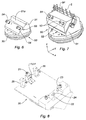
- This is first mounted on a removable support 20 as seen on the figure 3 .
- It is an isostatic assembly according to the three axes of a rectangle trihedron, in particular of the reference trihedron of the sector with a maintenance in translation along the three axes of the reference trihedron, by the flange 21 arranged on the side of the platform 18 at the center of the latter and which ensures the wedging in the three directions of the trihedron, and three rotational locking supports by the flanges 22, 23 at the ends of the inner platform 17 and the support 24 in the center not visible on the figure 3 .
- the assembly further comprises two vibration damping stirrups 25 and 26 disposed on either side of the flange 21.
- the angle of the plane of the sector is chosen so as to take account of that of the plane of the trailing edge zone with respect to this same plane. It is preferable that the machined surfaces of the BF are parallel to the axis of the machining tool such as a spindle. In the case of a five-axis numerical control machine, for example, this makes it possible to avoid positioning errors of the rotary axes (that is to say the 4th and 5th axes) of the machine.
- the support 20 is itself mounted on the plate 30 of the numerically controlled machine, not shown, via a base 31.
- the acquisition by probing by means of a suitable apparatus, of the position of a certain number of points on the blade and appropriate software, for example using the method of least squares, can calculate the corrections to be made to the reference trihedron of the assembly on the machining machine.
- This correction is made using 3 rotations around the X, Y, Z axes and a translation of the origin in the X, Y, Z directions (linear axes of the machine).
- the machining trihedron coincides with the main axes of the blade, 11 to 16 respectively, to be machined.
- the definition of the trihedron is related to the configuration of the machine as well as the possibility of palpating along 3 axes (the axes of rotation being deactivated).
- the positioning of the machined area of the blade parallel to the axis of the spindle induces that the axis X is the radial axis of the blade relative to the motor axis, the axis Z the axis of rotation of the plate , perpendicular to the plane of the plate, the Y axis completing the direct trihedron.
- the XY plane consists of the bearing face of the plate. It should be noted that the setting of the machining trihedron must be made for each of the blades of the distributor sector.
- It comprises the acquisition, by probing by means of a suitable probing apparatus with or without contact, of the position of a certain number of points along the trailing edge BF of the blade to be machined. These points are those defined on the theoretical 3D model of the blade in the CAD / CAM software.
- the reference mark is that of the machining trihedron.
- the number of points is preferably at least three.
- a plurality of induced points is defined.
- the set of points of contact tools / part defining the machining of the intrados and extrados must be contained in tiles, so we add the point N1 and the point N7 then the points N8 to N14. These are at the intersection of the rope passing through the probed points and the trailing edge.
- the points N1 and N7 which are too close to the platform to be palpated are obtained by translation of the adjacent points N2 and N6.
- the points N1 to N14 thus delimit the tops of machining tiles, C1 to C6.
- the value of the delta (N) deviations between the measured or induced position and the position on the theoretical model is calculated. Due to the calibration of the reference axes, this difference is measured along the main axis X.
- the quantity of material to be removed is defined on the one hand by the position of the contact of the tool in the tile and the value of the delta (N) deviations measured on each vertex of the tile concerned.
- the method of determining the amount of material to be removed by machining is described more precisely with reference to the example of figure 4 .
- the tiles are four-sided polygons, but they could have a number of different sides.
- Each point P is defined with respect to the vertices or nodes of the tile in which it is located by means of four coefficients, called weighting coefficients CPi (where i is the reference number of the node in question).
- Each weighting coefficient corresponds to the weight to be assigned to the corresponding node so that the point P is the center of gravity of these four knots. In other words, the closer the point P is to a node, the higher the coefficient assigned to this node, and conversely, the most distant nodes are assigned a low coefficient.
- these weighting coefficients are reduced proportionally to each other so that their sum is equal to 1.
- the four coefficients are equal to 0, 25; if it is close to one of the nodes, as we see on the figure 4 , the coefficient CP1 will be equal to 0.5 while the other three will be respectively equal to 0.35 for CP2, 0.10 for CP7 and 0.05 for CP8.
- the file constituted by the weightings of the points P to be scanned by the machining tool and by the corresponding orientations of the axis of the tool is then converted into a format understandable by the numerically controlled machine and loaded into its software.
- the next step is to define a delta positioning gap for all points of contact between the part and the tool during finishing machining.
- the calculation of this delta takes into account the weighting coefficients of the point P calculated previously and the delta (Ni) deviations of the nodes of the cell in which is the point P.
- the delta with the point P that is to say the correction to be made to the point P of the surface of the blade, is defined as being equal to the sum of the values obtained by multiplying each delta of a node by the weighting coefficient associated with it.
- delta (P) is equal to CP1 * delta (N1) + CP2 * delta (N2) + CP7 * delta (N7) + CP8 * delta (N8).
- delta P ⁇ CPi * delta Or ' for i corresponding to l ' index of the vertices of the d ' machining .
- This delta deviation (P) which extends along the X axis of the machining trihedron at the point P, determines the component of the correction to be applied to the Cartesian coordinates given to the program which controls the positioning of the tool during the process. finishing machining. In this case, the correction is made along the X axis alone.
- the machining is thus preferably carried out by a 5-axis numerical control machine tool for which the position of the tool is at all times corrected for the value resulting from the deltas of the nodes of the considered tile and the weighting coefficients of the point where is said tool.
- the machining is performed by rolling milling; that is to say by the cutting peripheral wall of the strawberry.
- the thickness removed during rough machining is of the order of a few tenths of mm or even a few mm (depending on the foundry allowance).
- the thickness removed during the finishing machining is of the order of a few hundredths of a millimeter.
- the value of the correction is a few tenths of a millimeter.
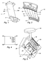
- the Figures 6 and 7 show the mounting of a blade on a mobile support 50.
- the support comprises a fixed jaw 51 whose surface 51a of contact with the moving blade is shaped to receive the upper surface of the movable blade.
- the figure 6 shows the fixed jaw only 51. It is fixed on the plate 30 and has a determined inclination. This inclination is chosen so as to allow the orientation of the machining tool in a direction such as that of the axis parallel to the axis of the spindle.
- the figure 7 shows the moving blade held between the jaw 51 and a removable jaw 52 so as to leave free the region of the trailing edge of the blade.
- the different positions of the probe S with its sphere in contact with the surface of the trailing edge zone are also shown.
- the assembly allows the probe to be positioned in each of the points whose position is to be measured.
- This arrangement allows the tool to machine rolling both sides, intrados and extrados of the blade and the rope.
- the two jaws are tightened by the screws 53.
- the clamping movement of the movable jaw against the fixed jaw is ensured by guiding along guide pins 54.
- the screws allow sufficient clamping to reduce the deformation of the blade.
- the fixed jaw 51 comprises a stop 55 for the platform of the blade root to wedge the blade in axial position.
- Machining is carried out in the same manner as described above for a distributor sector blade.
- the figure 8 shows the support 20 for dispenser sector without the coin.
- the elements of the isostatic fixation are seen with on one side the fastening flange 21 for immobilization in the three directions.
- On the other side we see the three supports for immobilization in rotation around the three axes.
- Vibration-damping stirrups 25 and 26 are arranged on either side of the flange 21. These stirrups are fixed by screws to the base and comprise bearing pads bearing against the faces of the platform. preventing the platform from vibrating.
Landscapes
- Engineering & Computer Science (AREA)
- Manufacturing & Machinery (AREA)
- Physics & Mathematics (AREA)
- General Physics & Mathematics (AREA)
- Human Computer Interaction (AREA)
- Automation & Control Theory (AREA)
- Theoretical Computer Science (AREA)
- Mechanical Engineering (AREA)
- Evolutionary Computation (AREA)
- Geometry (AREA)
- General Engineering & Computer Science (AREA)
- Computer Hardware Design (AREA)
- Turbine Rotor Nozzle Sealing (AREA)
- Architecture (AREA)
- Software Systems (AREA)
- Milling Processes (AREA)
Description
La présente invention concerne la fabrication d'aubes de turbomachines et plus particulièrement le domaine de l'usinage de finition de telles pièces par exemple issues de la fonderie.The present invention relates to the manufacture of turbomachine blades and more particularly to the field of finishing machining of such parts, for example from the foundry.
L'amélioration des performances des moteurs à turbine à gaz passe par la réalisation d'aubages au profil aérodynamique optimisé. En particulier on cherche à obtenir des aubes présentant un bord de fuite, BF, d'épaisseur aussi faible que possible compte tenu de contraintes de tenue mécanique et de fabrication. Ainsi, dans le domaine aéronautique, pour un moteur à turbine à gaz à double corps, tel qu'un turboréacteur multiflux, un objectif est la fabrication d'aubes mobiles pour les étages de la turbine à basse pression dont l'épaisseur du bord de fuite est aussi faible que 0,2 mm. Pour les aubes formant les distributeurs des étages à basse pression, l'épaisseur visée est 0,5 mm.Improving the performance of gas turbine engines requires optimized aerodynamic blading. In particular, it is sought to obtain blades having a trailing edge, BF, of thickness as small as possible taking into account constraints of mechanical strength and fabrication. Thus, in the aeronautical field, for a dual-body gas turbine engine, such as a multi-stream turbojet engine, an objective is the manufacture of blades for the stages of the low-pressure turbine whose thickness of the leakage is as low as 0.2 mm. For the blades forming the distributors of the low pressure stages, the target thickness is 0.5 mm.
Les aubages mentionnés ci-dessus sont généralement fabriqués par fonderie et coulée de métal dans un moule selon la technique dite à la cire perdue qui permet d'obtenir directement la forme souhaitée de la pale sans passer par la mise en oeuvre d'étapes d'usinage pour parvenir à la pièce finie.The blades mentioned above are generally manufactured by casting and casting of metal in a mold according to the so-called lost wax technique which makes it possible to obtain directly the desired shape of the blade without going through the implementation of steps of machining to reach the finished part.
Cependant, les procédés de fonderie en l'état actuel de la technique ne permettent pas d'obtenir des aubages avec des bords de fuite aussi fins. Par fonderie, on obtient au mieux des aubages ayant une épaisseur de bord de fuite de l'ordre de 0,7 mm pour les alliages à base nickel ou cobalt.However, foundry processes in the current state of the art do not allow to obtain blading with such thin trailing edges. By casting, the best results are obtained with blades with a trailing edge thickness of about 0.7 mm for nickel-based or cobalt-based alloys.
Ainsi, face aux besoins en amélioration des performances aérodynamiques des turbomachines, les techniques de fonderie ont atteint leurs limites quant à la finesse des bords de fuite. Un usinage complémentaire est nécessaire.Thus, in view of the need to improve the aerodynamic performance of turbomachines, foundry techniques have reached their limits as to the fineness of the trailing edges. Additional machining is necessary.
Cependant un simple usinage du bord de fuite de manière à réduire son épaisseur ne permettrait pas de parvenir à la finesse souhaitée car les pièces brutes issues de fonderie - ainsi que cela l'a été révélé par des mesures sans contact des épaisseurs - présentent des déformations le long du bord de fuite de la pale. L'examen de ces déformations a permis de constater qu'elles présentent une forme comparable à celle qui résulterait d'un flambage de la pale. Le document
Partant de ces constations, la demanderesse s'est fixé comme objectif la mise au point d'un procédé permettant de fabriquer des aubages de turbomachine dont la finesse du bord de fuite satisfait aux exigences actuelles d'amélioration de leurs performances aérodynamiques.Based on these observations, the Applicant has set itself the goal of developing a method for manufacturing turbomachine blades whose fineness of the trailing edge meets the current requirements to improve their aerodynamic performance.
La présente invention parvient à la réalisation de cet objectif avec un procédé de fabrication d'une aube de turbomachine, l'aube comportant une pale et le profil de la pale présentant un modèle théorique numérique, comprenant la fabrication d'une ébauche avec une surépaisseur le long du bord de fuite de la pale par rapport au profil théorique,
caractérisé par le fait que l'on enlève ladite surépaisseur par un usinage adaptatif, comprenant les étapes suivantes :
- Positionnement de l'ébauche dans un repère de référence,
- Acquisition par palpage en un nombre déterminé de points sur une première face de l'ébauche, le long du bord de fuite, de la position desdits points dans le repère de référence,
- Détermination des écarts de position selon une direction avec les points correspondants du modèle théorique,
- Elaboration de carreaux d'usinage sur ladite première face de l'ébauche, les sommets des carreaux étant déterminés à partir desdits points palpés,
- Détermination de la quantité de matière à enlever à la surface des carreaux, celle-ci étant une fonction de la position des points du carreau par rapport aux sommets des carreaux et desdits écarts de position, et son usinage.
characterized by the fact that said excess thickness is removed by adaptive machining, comprising the following steps:
- Positioning of the blank in a reference frame,
- Acquisition by probing in a determined number of points on a first face of the blank, along the trailing edge, of the position of said points in the reference mark,
- Determination of positional deviations in one direction with the corresponding points of the theoretical model,
- Elaboration of machining tiles on said first face of the blank, the tops of the tiles being determined from said probed points,
- Determination of the amount of material to be removed from the surface of the tiles, which is a function of the position of the points of the tile relative to the tops of the tiles and said positional deviations, and its machining.
Le procédé de l'invention permet d'effectuer les opérations de finition sur une machine outil à commande numérique assurant une grande précision de l'usinage et un profil satisfaisant aux contraintes aérodynamiques. En particulier aucun ressaut n'apparaît, sur la face traitée entre la portion de surface usinée et la surface adjacente. L'usinage est dit adaptatif car la trajectoire de l'outil d'usinage s'adapte à la géométrie de la pièce en cours d'usinage.The method of the invention allows finishing operations on a numerically controlled machine tool ensuring high precision machining and a profile satisfying the aerodynamic constraints. In particular, no protrusion appears on the treated face between the machined surface portion and the adjacent surface. The machining is said to be adaptive because the trajectory of the machining tool adapts to the geometry of the part being machined.
Conformément à une autre caractéristique, la surépaisseur à usiner est ménagée sur l'extrados, sur l'intrados et/ou sur la corde. En particulier une première surépaisseur est éliminée sur l'extrados qui constitue la première face. Lorsque la surépaisseur s'étend sur les deux faces, on extrapole le fait que la valeur de la déformation de la pale à l'intrados est similaire à celle de l'extrados mais de sens opposé. On utilise ainsi la correction mesurée en chaque point de la première face, pour déterminer la correction à usiner sur la face opposée. Cette correction est égale en valeur et opposée en direction.According to another characteristic, the extra thickness to be machined is provided on the upper surface, on the lower surface and / or on the rope. In particular, a first thickness is eliminated on the extrados which constitutes the first face. When the extra thickness extends on both sides, it is extrapolated that the value of the deformation of the blade on the underside is similar to that of the extrados but in the opposite direction. The correction measured at each point of the first face is thus used to determine the correction to be machined on the opposite face. This correction is equal in value and opposite in direction.
Enfin on réduit, le cas échéant, la corde de l'aube le long du bord de fuite pour parvenir au profil du bord de fuite de l'épaisseur souhaitée.Finally, if necessary, the rope of the blade is reduced along the trailing edge to reach the profile of the trailing edge of the desired thickness.
Le nombre de points palpés est au minimum de trois. Ils sont répartis entre les deux plateformes pour un secteur de distributeur ou entre la plateforme du pied et le sommet de la pale pour une aube mobile ils sont disposés parallèlement au bord de fuite. Notamment les sommets des carreaux d'usinage comprennent les points palpés et des points dont la position s'en déduit par translation le long de la corde passant par les points palpés.The number of probed points is at least three. They are distributed between the two platforms for a distributor sector or between the platform of the foot and the top of the blade for a moving blade they are arranged parallel to the trailing edge. In particular, the vertices of the machining tiles comprise the probed points and points whose position is deduced by translation along the rope passing through the probed points.
L'usinage est effectué de préférence par un fraisage en roulant, c'est-à-dire que la matière est enlevée par la paroi périphérique coupante d'un outil cylindrique et non par l'extrémité distale de celui-ci.The machining is preferably performed by rolling milling, that is to say that the material is removed by the cutting peripheral wall of a cylindrical tool and not by the distal end thereof.
D'autres moyens d'usinage entrent dans le cadre du procédé de l'invention. Par exemple il peut s'agir d'un polissage adaptatif par bande au moyen d'une machine de polissage ou robot de polissage. II peut s'agir d'un usinage adaptatif par meulage ou rectification. Il peut s'agir encore d'un usinage par robot de fraisage et non par machine outil. Plus généralement l'invention couvre tout procédé et outil d'enlèvement de matière adaptatif.Other machining means are within the scope of the process of the invention. For example, it may be an adaptive polishing by tape using a polishing machine or polishing robot. It may be an adaptive machining by grinding or grinding. It may still be machining by robotic milling and not by machine tool. More generally, the invention covers any process and tool for the removal of adaptive material.
Conformément à une autre caractéristique et selon un mode de réalisation avantageux, le procédé comprend le montage de l'aubage sur un support amovible et le montage du support amovible sur une machine outil à commande numérique avec un trièdre d'usinage, l'usinage étant effectué avec enlèvement de matière selon une composante des 3 axes du trièdre d'usinage.According to another characteristic and according to an advantageous embodiment, the method comprises mounting the blading on a removable support and mounting the removable support on a numerically controlled machine tool with a machining trihedron, machining being performed with removal of material according to a component of the 3 axes of the machining trihedron.
Plus particulièrement, selon une première application, l'aubage étant une aube mobile de turbine, l'aubage est fixé sur le support amovible en étant serré entre un mors amovible et un mors fixe de manière à former un ensemble rigide. Le mors fixe est conformé au profil théorique d'une face de la pale, de préférence son extrados, tout en laissant libre le bord de fuite à usiner. La pièce est serrée sur la plus grande surface possible afin de réduire les vibrations tout en maintenant l'accessibilité d'une part au palpeur pour les mesures puis, d'autre part, aux outils pour l'usinage.More particularly, according to a first application, the blade being a turbine blade, the blade is fixed on the removable support being clamped between a removable jaw and a fixed jaw so as to form a rigid assembly. The fixed jaw is shaped to the theoretical profile of a face of the blade, preferably its upper surface, while leaving the trailing edge free to machine. The workpiece is clamped over the largest possible area in order to reduce vibrations while maintaining accessibility on the one hand to the probe for measurements and, on the other hand, tools for machining.
Selon une seconde application, l'aubage faisant partie d'un secteur de distributeur de turbine, le support amovible est agencé pour un montage isostatique du secteur dans le support amovible. Le montage est isostatique car il bloque les six degrés de liberté de la pièce (3 translations et 3 rotations). Il reprend des points d'appui identiques à ceux utilisés pour l'opération de contrôle après usinage. Conformément à une autre caractéristique, le support amovible comprend un moyen pour amortir les vibrations produites lors de l'usinage.According to a second application, the blade being part of a sector of turbine distributor, the removable support is arranged for an isostatic mounting of the sector in the removable support. The assembly is isostatic because it blocks the six degrees of freedom of the room (3 translations and 3 rotations). It takes the same points of support as those used for the control operation after machining. According to another characteristic, the removable support comprises means for damping the vibrations produced during machining.
Selon cette seconde application, l'usinage de chacune des aubes du secteur de distributeur comprend une étape préalable de recalage au mieux de l'aube par rapport au trièdre d'usinage sur la machine outil.According to this second application, the machining of each of the vanes of the distributor sector comprises a prior step of resetting the blade to the best of the machining trihedron on the machine tool.
La présente invention porte également sur le support amovible pour la mise en oeuvre du procédé, l'aubage étant une aube mobile de turbine.The present invention also relates to the removable support for the implementation of the method, the blade being a turbine blade.
Le support d'usinage d'une aube mobile de turbomachine comprenant une embase agencée pour la fixation du support au plateau d'une machine outil à commande numérique et un moyen de fixation de l'aube sur l'embase, est caractérisé par le fait que le moyen de fixation comprend un mors fixe solidaire de l'embase et un mors libre, le mors fixe présentant une surface d'appui apte à recevoir la pale de ladite aube et qui est conformée au profil théorique de ladite pale.The machining support of a mobile turbine engine blade comprising a base arranged for fixing the support to the plate of a numerically controlled machine tool and a means for fixing the blade on the base, is characterized by the fact that that the fixing means comprises a fixed jaw secured to the base and a free jaw, the fixed jaw having a bearing surface adapted to receive the blade of said blade and which is shaped to the theoretical profile of said blade.
Le support présente en particulier les caractéristiques suivantes, prises seules ou en combinaison :
- Les surfaces usinées du BF son t de préférence parallèles à l'axe de l'outil d'usinage tel qu'une broche. Dans le cas d'une machine à commande numérique à cinq axes, ceci permet d'éviter les erreurs de positionnement des axes rotatifs (c'est-à-dire les 4ème et 5ème axes) de la machine.
- Le support est conformé de manière à ménager une zone libre d'usinage le long du bord de fuite de la pale.
- Le support est conformé de manière à ménager une zone libre d'usinage le long et de part et d'autre du bord de fuite de la pale.
- Le support comprend des moyens de guidage en translation du mors libre.
- Le support comprend des moyens de serrage du mors libre sur le mors fixe avec interposition d'une pale, aptes à redresser la pale de l'aube, lorsque celle-ci comprend des déformations telles que de flambage.
- Le support présente une butée parallèle à l'axe du profil théorique de la pale, apte à recevoir en appui la plateforme de pied d'aube.
- The machined surfaces of the BF are preferably parallel to the axis of the machining tool such as a spindle. In the case of a machine with five-axis numerical control, this makes it possible to avoid positioning errors of the rotary axes (that is to say the 4th and 5th axes) of the machine.
- The support is shaped to provide a free machining area along the trailing edge of the blade.
- The support is shaped so as to provide a free machining zone along and on either side of the trailing edge of the blade.
- The support comprises guide means in translation of the free jaw.
- The support comprises clamping means of the free jaw on the fixed jaw with the interposition of a blade, able to straighten the blade of the blade, when it comprises deformations such as buckling.
- The support has an abutment parallel to the axis of the theoretical profile of the blade, adapted to receive in support the platform of blade root.
La présente invention porte également sur le support d'un secteur de distributeur de turbomachine.The present invention also relates to the support of a turbomachine distributor sector.
Le support d'usinage d'un secteur de distributeur de turbomachine obtenu par coulée de métal avec une pluralité de pales solidaires à une extrémité d'une plateforme intérieure et à l'autre extrémité d'une plateforme extérieure, comprenant une embase avec une face plane agencée pour la fixation du support au plateau d'une machine outil à commande numérique et un moyen de fixation du secteur de distributeur sur l'embase, est caractérisé par le fait que le moyen de fixation est agencé pour que les zones des bords de fuite des pales qui sont à usiner sont orientées perpendiculairement à ladite face plane.The machining support of a turbine engine valve sector obtained by metal casting with a plurality of integral blades at one end of an inner platform and at the other end of an outer platform, comprising a base with a face plane arranged for fixing the support to the plate of a numerically controlled machine tool and a fixing means of the distributor sector on the base, is characterized in that the fixing means is arranged so that the zones of the edges of leakage of the blades that are to be machined are oriented perpendicularly to said plane face.
Le support présente en particulier les caractéristiques suivantes prises seules ou en combinaison :
- Le moyen de fixation comprend un appui de la plateforme intérieure à l'embase et un appui de la plateforme extérieure à l'embase.
- Le moyen de fixation comprend une bride d'immobilisation de la plateforme extérieure sur son appui, selon les trois axes principaux du secteur de distributeur.
- Le moyen de fixation comprend des brides d'immobilisation de la plateforme intérieure en appui sur l'embase, avec immobilisation en rotation autour des trois axes principaux du secteur de distributeur.
- Le support comprend des moyens d'amortissement des vibrations.
- Les moyens d'amortissement des vibrations comprennent au moins un étrier solidaire de l'embase et avec des surfaces d'appui contre les deux faces opposées d'une plateforme, notamment la plateforme extérieure.
- Le support comprend deux étriers d'amortissement des vibrations un de chaque côte de la bride de fixation de la plateforme.
- The fixing means comprises a support of the inner platform to the base and a support of the outer platform to the base.
- The fixing means comprises an immobilizing flange of the outer platform on its support, along the three main axes of the dispenser sector.
- The fixing means comprises immobilization flanges of the inner platform resting on the base, with immobilization in rotation around the three main axes of the distributor sector.
- The support comprises vibration damping means.
- The vibration damping means comprise at least one bracket integral with the base and with bearing surfaces against the two opposite faces of a platform, in particular the outer platform.
- The support includes two vibration damping brackets one on each side of the platform clamp.
La présente invention porte également sur un dispositif de mise en oeuvre du procédé décrit ci-dessus, comprenant :
- o des moyens de positionnement de l'ébauche dans un repère de référence,
- o des moyens d'acquisition par palpage en un nombre déterminé de points (Ni) sur une première face de l'ébauche, le long du bord de fuite, de la position desdits points dans le repère de référence,
- o des moyens de détermination des écarts de position delta(Ni) selon une direction avec les points correspondants du modèle théorique,
- o des moyens d'élaboration de carreaux d'usinage sur ladite face de l'ébauche, les sommets des carreaux étant déterminés à partir desdits points (Ni),
- o des moyens de détermination de la quantité de matière à enlever à la surface des carreaux, celle-ci étant une fonction de la position des points (Nc) du carreau par rapport aux sommets des carreaux et desdits écarts de position, et
- o des moyens d'usinage de la pale
- o means for positioning the blank in a reference frame,
- o probing acquisition means in a given number of points (Ni) on a first face of the blank, along the trailing edge, of the position of said points in the reference frame,
- o means for determining the delta (Ni) position deviations in one direction with the corresponding points of the theoretical model,
- o means for producing machining tiles on said face of the blank, the vertices of the tiles being determined from said points (Ni),
- o means for determining the amount of material to be removed from the surface of the tiles, the latter being a function of the position of the points (Nc) of the tile relative to the tops of the tiles and said positional deviations, and
- o machining means of the blade
L'invention sera mieux comprise et d'autres buts et détails, caractéristiques et avantages de celle-ci apparaîtront plus clairement avec la description explicative détaillée qui suit d'un mode de réalisation de l'invention donné à titre d'exemple purement illustratif et non limitatif, en référence aux dessins schématiques annexés, sur lesquels
- La
figure 1 représente une aube de turbine ; - La
figure 2 représente un secteur de distributeur de turbine ; - La
figure 3 représente un secteur de distributeur monté sur un support amovible avec indication des points constituant les carreaux d'usinage définissant la zone de correction adaptative en bord de fuite ; - La
figure 4 illustre comment le calcul de la position de l'outil d'usinage est déterminé ; - La
figure 5 montre l'outil d'usinage en action le long du bord fuite d'une pale ; - La
figure 6 montre un support pour aube isolée, mobile ; - La
figure 7 montre le support de lafigure 6 avec une aube entre les mors ainsi que la tige et la bille du palpeur à différentes positions de palpage ; - La
figure 8 montre le support pour secteur de distributeur de turbine.
- The
figure 1 represents a turbine blade; - The
figure 2 represents a turbine distributor sector; - The
figure 3 represents a distributor sector mounted on a removable support with indication of the points constituting the machining tiles defining the adaptive correction zone at the trailing edge; - The
figure 4 illustrates how the calculation of the position of the machining tool is determined; - The
figure 5 shows the machining tool in action along the trailing edge of a blade; - The
figure 6 shows a support for isolated, mobile dawn; - The
figure 7 shows the support of thefigure 6 with a blade between the jaws as well as the rod and the ball of the probe at different probing positions; - The
figure 8 shows the support for turbine distributor sector.
La
La
On décrit le procédé appliqué à la finition des pales 11 à 16 d'un secteur de distributeur 10 monobloc à six pales. Celui-ci est d'abord monté sur un support amovible 20 comme on le voit sur la
L'angle du plan du secteur est choisi de manière à tenir compte de celui du plan de la zone du bord de fuite par rapport à ce même plan. Il est préférable que les surfaces usinées du BF soient parallèles à l'axe de l'outil d'usinage tel qu'une broche. Dans le cas d'une machine à commande numérique à cinq axes par exemple, ceci permet d'éviter les erreurs de positionnement des axes rotatifs (c'est-à-dire les 4ème et 5ème axes) de la machine.The angle of the plane of the sector is chosen so as to take account of that of the plane of the trailing edge zone with respect to this same plane. It is preferable that the machined surfaces of the BF are parallel to the axis of the machining tool such as a spindle. In the case of a five-axis numerical control machine, for example, this makes it possible to avoid positioning errors of the rotary axes (that is to say the 4th and 5th axes) of the machine.
Le support 20 est lui-même monté sur le plateau 30 de la machine à commande numérique, non représentée, par l'intermédiaire d'un socle 31.The
Une fois le support 20 monté sur le plateau de la machine outil, on procède au calage au mieux du trièdre d'usinage par rapport à la pale à usiner. Dans ce but, on effectue l'acquisition, par palpage au moyen d'un appareil approprié, de la position d'un certain nombre de points sur la pale et un logiciel approprié, par exemple utilisant la méthode des moindres carrés, permet de calculer les corrections à apporter au trièdre de référence du montage sur la machine d'usinage. Cette correction est réalisée à l'aide de 3 rotations autour des axes X, Y, Z et d'une translation de l'origine dans les directions X, Y, Z (axes linéaires de la machine).Once the
Le trièdre d'usinage coïncide avec les axes principaux de la pale, 11 à 16 respectivement, à usiner. La définition du trièdre est liée à la configuration de la machine ainsi qu'à la possibilité de palper selon 3 axes (les axes de rotation étant désactivés). Le positionnement de la zone usinée de la pale parallèlement à l'axe de la broche induit que l'axe X soit l'axe radial de la pale par rapport à l'axe moteur, l'axe Z l'axe de rotation du plateau, perpendiculaire au plan du plateau, l'axe Y complétant le trièdre direct. Le plan XY est constitué de la face d'appui du plateau. Il est à noter que le calage du trièdre d'usinage doit être effectué pour chacune des pales du secteur de distributeur.The machining trihedron coincides with the main axes of the blade, 11 to 16 respectively, to be machined. The definition of the trihedron is related to the configuration of the machine as well as the possibility of palpating along 3 axes (the axes of rotation being deactivated). The positioning of the machined area of the blade parallel to the axis of the spindle induces that the axis X is the radial axis of the blade relative to the motor axis, the axis Z the axis of rotation of the plate , perpendicular to the plane of the plate, the Y axis completing the direct trihedron. The XY plane consists of the bearing face of the plate. It should be noted that the setting of the machining trihedron must be made for each of the blades of the distributor sector.
Une fois le calage effectué, on procède à l'usinage dit adaptatif du bord de fuite BF. Cette technique d'usinage est décrite dans la demande de brevet
Elle comprend l'acquisition, par palpage au moyen d'un appareil de palpage approprié avec ou sans contact, de la position d'un certain nombre de points le long du bord de fuite BF de la pale à usiner. Ces points sont ceux définis sur le modèle théorique 3D de la pale dans le logiciel CFAO. Le repère de référence est celui du trièdre d'usinage.It comprises the acquisition, by probing by means of a suitable probing apparatus with or without contact, of the position of a certain number of points along the trailing edge BF of the blade to be machined. These points are those defined on the theoretical 3D model of the blade in the CAD / CAM software. The reference mark is that of the machining trihedron.
Ici, on mesure la position des points N2 à N6,
A partir de ces points dont la position a été mesurée, on définit une pluralité de points induits. L'ensemble des points de contact outils/pièce définissant l'usinage de l'intrados et de l'extrados doit être contenu dans des carreaux, on ajoute donc le point N1 et le point N7 puis les points N8 à N14. Ces derniers sont à l'intersection de la corde passant par les points palpés et le bord de fuite. Les points N1 et N7 qui sont trop près de la plateforme pour pouvoir être palpés sont obtenus par translation des points N2 et N6 adjacents. Les points N1 à N14 délimitent ainsi les sommets de carreaux d'usinage, C1 à C6.From these points whose position has been measured, a plurality of induced points is defined. The set of points of contact tools / part defining the machining of the intrados and extrados must be contained in tiles, so we add the point N1 and the point N7 then the points N8 to N14. These are at the intersection of the rope passing through the probed points and the trailing edge. The points N1 and N7 which are too close to the platform to be palpated are obtained by translation of the adjacent points N2 and N6. The points N1 to N14 thus delimit the tops of machining tiles, C1 to C6.
Pour chacun des points N1 à N14, on calcule alors la valeur des écarts delta (N) entre la position mesurée ou induite et la position sur le modèle théorique. En raison du calage des axes de référence, cet écart est mesuré le long de l'axe principal X. Pour chaque carreau d'usinage et en chaque zone de contact de l'outil avec la surface de l'aube à l'intérieur des carreaux, la quantité de matière à enlever est définie d'une part par la position du contact de l'outil dans le carreau et la valeur des écarts delta(N) mesurés sur chaque sommet du carreau concerné.For each of the points N1 to N14, the value of the delta (N) deviations between the measured or induced position and the position on the theoretical model is calculated. Due to the calibration of the reference axes, this difference is measured along the main axis X. For each machining tile and in each contact zone of the tool with the surface of the blade inside the The quantity of material to be removed is defined on the one hand by the position of the contact of the tool in the tile and the value of the delta (N) deviations measured on each vertex of the tile concerned.
On décrit plus précisément le mode de détermination de la quantité de matière à enlever par usinage en référence à l'exemple de la
Chaque point P est défini par rapport aux sommets ou noeuds du carreau dans lequel il se trouve à l'aide de quatre coefficients, dits coefficients pondérateurs CPi (i étant le numéro de référence du noeud en question). Chaque coefficient pondérateur correspond au poids dont il faut affecter le noeud correspondant pour que le point P soit le barycentre de ces quatre noeuds. En d'autres termes plus le point P est proche d'un noeud, plus le coefficient, affecté à ce noeud, est élevé et, inversement, les noeuds les plus éloignés se voient affectés d'un coefficient faible. Afin de rendre unique la définition de ces coefficients pondérateurs, ils sont réduits proportionnellement les uns aux autres pour que leur somme soit égale à 1. A titre d'exemple si le point P est au centre du carreau les quatre coefficients sont égaux à 0,25 ; s'il est proche d'un des noeuds, tel qu'on le voit sur la
Le fichier constitué par les pondérations des points P à balayer par l'outil d'usinage et par les orientations correspondantes de l'axe de l'outil est alors converti en un format compréhensible par la machine à commande numérique et chargé dans son logiciel.The file constituted by the weightings of the points P to be scanned by the machining tool and by the corresponding orientations of the axis of the tool is then converted into a format understandable by the numerically controlled machine and loaded into its software.
L'étape suivante consiste à définir un écart de positionnement delta pour tous les points de contact entre la pièce et l'outil lors de l'usinage de finition. Pour cela le calcul de ce delta prend en compte les coefficients pondérateurs du point P calculés précédemment et les écarts delta(Ni) des noeuds du carreau dans lequel se trouve le point P. Le delta au point P, c'est-à-dire la correction à apporter au point P de la surface de la pale, est défini comme étant égal à la somme des valeurs obtenues en multipliant chaque delta d'un noeud par le coefficient pondérateur qui lui est associé.The next step is to define a delta positioning gap for all points of contact between the part and the tool during finishing machining. For that, the calculation of this delta takes into account the weighting coefficients of the point P calculated previously and the delta (Ni) deviations of the nodes of the cell in which is the point P. The delta with the point P, that is to say the correction to be made to the point P of the surface of the blade, is defined as being equal to the sum of the values obtained by multiplying each delta of a node by the weighting coefficient associated with it.
Dans l'exemple du point P situé dans le carreau formé par les quatre noeuds N1, N2, N7 et N8, la valeur de delta(P) est égale à CP1*delta (N1) + CP2*delta (N2) + CP7*delta (N7) + CP8*delta (N8).In the example of the point P situated in the cell formed by the four nodes N1, N2, N7 and N8, the value of delta (P) is equal to CP1 * delta (N1) + CP2 * delta (N2) + CP7 * delta (N7) + CP8 * delta (N8).
Plus généralement, on peut l'exprimer par la formule, 
Cet écart delta(P), qui s'étend selon l'axe X du trièdre d'usinage au point P, détermine la composante de la correction à appliquer aux coordonnées cartésiennes données au programme qui pilote le positionnement de l'outil lors de l'usinage de finition. Dans le cas présent, la correction est apportée selon l'axe X seul.This delta deviation (P), which extends along the X axis of the machining trihedron at the point P, determines the component of the correction to be applied to the Cartesian coordinates given to the program which controls the positioning of the tool during the process. finishing machining. In this case, the correction is made along the X axis alone.
L'usinage s'effectue ainsi de préférence par une machine-outil à commande numérique 5 axes pour laquelle la position de l'outil est à tout instant corrigée de la valeur issue des deltas des noeuds du carreau considéré et des coefficients pondérateurs du point où se trouve ledit outil. De préférence l'usinage est effectué par fraisage en roulant ; c'est-à-dire par la paroi périphérique coupante de la fraise.The machining is thus preferably carried out by a 5-axis numerical control machine tool for which the position of the tool is at all times corrected for the value resulting from the deltas of the nodes of the considered tile and the weighting coefficients of the point where is said tool. Preferably the machining is performed by rolling milling; that is to say by the cutting peripheral wall of the strawberry.
Une fois que l'on a usiné la première face pour amener sa position à celle de la surface du modèle théorique, on procède à la détermination de la correction d'usinage sur la face opposée à la première, c'est à dire ici la face intrados. On part comme dans l'extrados des points initiaux N2 à N6. Le palpeur ne pouvant pas accéder entre les pales, on corrige de la même façon que l'on a corrigée sur l'extrados. On utilise les mêmes carreaux qu'à l'extrados et seuls les points de contacts outils/pièces sont différents.Once we have machined the first face to bring its position to that of the theoretical model surface, we proceed to the determination of the machining correction on the face opposite to the first, that is to say here the face down. We leave as in the extrados of the initial points N2 to N6. The probe can not access between the blades, it corrects in the same way that it has corrected on the extrados. The same tiles are used as on the extrados and only the tool / piece contact points are different.
Un exemple de déroulé des opérations de fraisage des pales d'un secteur de distributeur est le suivant :
- fraisage ébauche de la corde de chaque pale, une pale après l'autre, ce fraisage vise à conserver une surépaisseur,
- fraisage ébauche de l'intrados de chaque pale, une pale après l'autre,
- fraisage semi-finition et finition de l'extrados de chaque pale, une pale après l'autre,
- fraisage finition de l'intrados de chaque pale, une pale après l'autre,
- fraisage finition de la corde de chaque pale, une pale après l'autre.
- rough milling of the rope of each blade, one blade after another, this milling aims at keeping an extra thickness,
- rough milling of the intrados of each blade, one blade after another,
- milling semi-finishing and finishing of the upper surface of each blade, one blade after another,
- milling finishing of the intrados of each blade, one blade after another,
- milling finishing the rope of each blade, one blade after another.
L'épaisseur enlevée lors de l'usinage d'ébauche est de l'ordre de quelques dixièmes de mm voire un quelques mm (en fonction de la surépaisseur de fonderie).The thickness removed during rough machining is of the order of a few tenths of mm or even a few mm (depending on the foundry allowance).
L'épaisseur enlevée lors de l'usinage de finition est de l'ordre de quelques centièmes de mm.The thickness removed during the finishing machining is of the order of a few hundredths of a millimeter.
La valeur de la correction est de quelques dixièmes de mm.The value of the correction is a few tenths of a millimeter.
On a représenté sur la
Les
On a représenté aussi les différentes positions du palpeur S avec sa sphère au contact de la surface de la zone du bord de fuite. Le montage permet au palpeur de se positionner en chacun des points dont on souhaite mesurer la position.The different positions of the probe S with its sphere in contact with the surface of the trailing edge zone are also shown. The assembly allows the probe to be positioned in each of the points whose position is to be measured.
Cette disposition permet à l'outil d'usiner en roulant les deux faces, intrados et extrados de la pale ainsi que la corde. Les deux mors sont serrés par les vis 53. Le déplacement de serrage du mors mobile contre le mors fixe est assuré par un guidage le long de pions de guidage 54. Les vis permettent un serrage suffisant pour réduire la déformation de la pale.This arrangement allows the tool to machine rolling both sides, intrados and extrados of the blade and the rope. The two jaws are tightened by the
Le mors fixe 51 comprend une butée 55 pour la plateforme de pied d'aube permettant de caler l'aube en position axiale.The fixed
On procède à l'usinage de la même façon que décrite plus haut pour une pale de secteur de distributeur.Machining is carried out in the same manner as described above for a distributor sector blade.
La
Les étriers 25 et 26 d'amortissement des vibrations sont disposés de part et d'autre de la bride 21. Ces étriers sont fixés par des vis à l'embase et comportent de coussinets d'appui venant en appui contre les faces de la plateforme empêchant la plateforme de vibrer.Vibration-damping
Claims (13)
- Method for manufacturing a turbine engine blade, the blade comprising a vane and the profile of the vane being defined by a theoretical digital model, involving the manufacture of a blank having a machining allowance along the trailing edge of the vane with respect to the theoretical profile, wherein said machining allowance is removed by adaptive machining, comprising the steps of:a) positioning the blank in a reference frame,b) acquiring, by probing at a given number of points (Ni) on a first face of the blank, along the trailing edge, the position of said points in the reference frame,c) determining the differences in position delta(Ni), in one direction, from corresponding points on the theoretical model,d) producing machining grids on said first face of the blank, the apexes of the grids being determined from said points (Ni),e) determining the quantity of material to be removed on the surface of the grids, this depending on the position of the points (Nc) on the grid with respect to the apexes of the grids and said position differences, andf) machining the vane.
- Method according to the preceding claim, in which the machining allowance to be machined is formed on the suction face and on the pressure face.
- Method according to claim 2, in which the machining allowance is also formed on the chord.
- Method according to any of the preceding claims, in which the points probed are at least three in number.
- Method according to the preceding claim, in which the points probed are arranged parallel to the trailing edge.
- Method according to any of the preceding claims, in which the apexes of the machining grids comprise the probed points Ni and points that are deduced by translation along the chord passing through the probed points.
- Method according to any of the preceding claims, comprising the machining of the face opposite to the first face, the quantity of material removed being determined by the position with respect to the apexes of the machining grids of the first face.
- Method according to any of the preceding claims, comprising the mounting of the blading on a removable support and the mounting of the removable support on a numerically controlled machine tool having a machining axis system, the machining being performed with removal of material in one of the directions of the machining axis system.
- Method according to the preceding claim, the blading being a rotor turbine blade, the blading of which is fixed to the removable support by being gripped between a removable jaw and a fixed jaw, the fixed jaw being machined to the theoretical profile of a face of the vane, leaving free the trading edge to be machined.
- Method according to claim 8, the blading forming part of a turbine nozzle sector, the removable support of which is arranged for isostatic mounting of the sector in the removable support.
- Method according to the preceding claim, in which the removable support comprises a means for damping the vibrations during machining.
- Method according to either claim 10 or claim 11, in which the machining of each of the blades of the nozzle sector comprises a prior step of best readjusting the blade with respect to the machining axis system on the machine tool.
- Device for implementing the method according to any of the preceding claims, comprising:a. means for positioning the blank in a reference frame,b. means for acquiring, by probing at a given number of points (Ni) on a first face of the blank, along the trailing edge, the position of said points in the reference frame,c. means for determining the position differences delta(Ni) in one direction from the corresponding points of the theoretical model,d. means for producing machining grids on said face of the blank, the apexes of the grids being determined from said points (Ni),e. means for determining the quantity of material to be removed on the surface of the grids, this depending on the position of the points (Nc) on the grid with respect to the apexes of the grids and said position differences, andf. means for machining the vane,wherein the positioning means comprise a removable support comprising a base for fixing to the platform of the machine tool and either a jaw rigidly connected to the base on the theoretical profile of a face of the vane of a turbine rotor blade to be machined, or
a means for the isostatic fixing of a nozzle sector to be machined on the base.
Applications Claiming Priority (2)
| Application Number | Priority Date | Filing Date | Title |
|---|---|---|---|
| FR1253764A FR2989608B1 (en) | 2012-04-24 | 2012-04-24 | METHOD FOR MACHINING THE LEFT EDGE OF A TURBOMACHINE BLADE |
| PCT/FR2013/050891 WO2013160601A1 (en) | 2012-04-24 | 2013-04-22 | Method for machining the trailing edge of a turbine engine blade |
Publications (3)
| Publication Number | Publication Date |
|---|---|
| EP2842007A1 EP2842007A1 (en) | 2015-03-04 |
| EP2842007B1 true EP2842007B1 (en) | 2016-08-24 |
| EP2842007B2 EP2842007B2 (en) | 2024-09-11 |
Family
ID=48468625
Family Applications (1)
| Application Number | Title | Priority Date | Filing Date |
|---|---|---|---|
| EP13723849.9A Active EP2842007B2 (en) | 2012-04-24 | 2013-04-22 | Method for machining the trailing edge of a turbine engine blade |
Country Status (8)
| Country | Link |
|---|---|
| US (1) | US10012976B2 (en) |
| EP (1) | EP2842007B2 (en) |
| CN (1) | CN104246635B (en) |
| BR (1) | BR112014026080B1 (en) |
| CA (1) | CA2870568C (en) |
| FR (1) | FR2989608B1 (en) |
| RU (1) | RU2628453C2 (en) |
| WO (1) | WO2013160601A1 (en) |
Families Citing this family (12)
| Publication number | Priority date | Publication date | Assignee | Title |
|---|---|---|---|---|
| FR3050131B1 (en) * | 2016-04-13 | 2018-04-27 | Safran Aircraft Engines | MACHINING PROCESS FOR MULTI-PALE DISPENSER |
| CN106363431A (en) * | 2016-10-08 | 2017-02-01 | 中国南方航空工业(集团)有限公司 | Machining method for tenon tooth of shrouded turbine blade |
| US10399189B2 (en) * | 2016-10-10 | 2019-09-03 | United Technologies Corporation | Airfoil aerodynamics |
| FR3081497B1 (en) | 2018-05-23 | 2020-12-25 | Safran Aircraft Engines | GROSS FOUNDRY BLADE WITH MODIFIED LEAKING EDGE GEOMETRY |
| US10955815B2 (en) | 2018-11-09 | 2021-03-23 | Raytheon Technologies Corporation | Method of manufacture using autonomous adaptive machining |
| CN109332772A (en) * | 2018-11-22 | 2019-02-15 | 中国航发沈阳黎明航空发动机有限责任公司 | A kind of aero-engine stator blade front and rear edge adaptive machining method |
| FR3095507B1 (en) * | 2019-04-29 | 2021-04-16 | Safran Aircraft Engines | DIMENSIONAL CONTROL PROCESS OF A TURBOMACHINE PART |
| US11066942B2 (en) | 2019-05-13 | 2021-07-20 | Rolls-Royce Plc | Systems and method for determining turbine assembly flow characteristics |
| US20210004636A1 (en) * | 2019-07-02 | 2021-01-07 | United Technologies Corporation | Manufacturing airfoil with rounded trailing edge |
| CN114952523B (en) * | 2021-02-26 | 2023-12-05 | 中国航发商用航空发动机有限责任公司 | Method and device for machining blade of aeroengine |
| FR3121618B1 (en) * | 2021-04-08 | 2023-02-24 | Safran Aircraft Engines | STORAGE HOLDER FOR A LOST WAX PIECE |
| JP7424589B2 (en) | 2021-11-19 | 2024-01-30 | 三菱重工業株式会社 | Processing method |
Family Cites Families (21)
| Publication number | Priority date | Publication date | Assignee | Title |
|---|---|---|---|---|
| US2681500A (en) * | 1949-07-18 | 1954-06-22 | Bristol Aeroplane Co Ltd | Method of manufacturing turbine or the like blades |
| DE1062499B (en) | 1955-08-09 | 1959-07-30 | Waldes Kohinoor Inc | Oval spring ring |
| US3099777A (en) * | 1960-07-08 | 1963-07-30 | Westinghouse Electric Corp | Digital position control servosystem |
| US3639992A (en) * | 1970-01-15 | 1972-02-08 | Chromalloy American Corp | Chord length gauge |
| SU1024184A1 (en) * | 1982-01-11 | 1983-06-23 | Производственное Объединение Турбостроения "Ленинградский Металлический Завод" | Method of working blade of mixed-flow hydraulic turbine |
| US5146670A (en) * | 1985-04-24 | 1992-09-15 | The Boeing Company | Profiling and deburring of workpieces |
| US5055752A (en) * | 1990-04-20 | 1991-10-08 | United Technologies Corporation | Method for machining airfoils |
| US5288209A (en) | 1991-12-19 | 1994-02-22 | General Electric Company | Automatic adaptive sculptured machining |
| DE10322340B4 (en) * | 2003-05-17 | 2006-09-14 | Mtu Aero Engines Gmbh | Method and device for milling free-form surfaces |
| DE102004008027A1 (en) * | 2004-02-19 | 2005-09-08 | Mtu Aero Engines Gmbh | Process for the production of adapted fluidic surfaces |
| GB0419381D0 (en) * | 2004-09-01 | 2004-10-06 | Renishaw Plc | Machine tool method |
| US7784183B2 (en) * | 2005-06-09 | 2010-08-31 | General Electric Company | System and method for adjusting performance of manufacturing operations or steps |
| IL174003A0 (en) | 2006-02-28 | 2006-08-01 | Shafir Production Systems Ltd | A method and apparatus for producing blades |
| AT503840B1 (en) * | 2006-06-30 | 2010-09-15 | Facc Ag | ROD ROD ARRANGEMENT FOR A TRANSMISSION |
| FR2913901B1 (en) * | 2007-03-20 | 2009-09-04 | Snecma Services Sa | PROCESS FOR REPAIRING FACTORY PARTS SUCH AS TURBOMACHINE BLADES OR DAM BLADES |
| FR2919897B1 (en) * | 2007-08-08 | 2014-08-22 | Snecma | TURBINE DISPENSER SECTOR |
| US8578579B2 (en) * | 2007-12-11 | 2013-11-12 | General Electric Company | System and method for adaptive machining |
| EP2143883A1 (en) * | 2008-07-10 | 2010-01-13 | Siemens Aktiengesellschaft | Turbine blade and corresponding casting core |
| FR2947197B1 (en) * | 2009-06-26 | 2011-07-15 | Snecma | METHOD FOR MANUFACTURING A FORGED PART WITH ADAPTIVE POLISHING |
| WO2011035798A1 (en) * | 2009-09-28 | 2011-03-31 | Siemens Aktiengesellschaft | Gas turbine nozzle arrangement and gas turbine |
| FR2961846B1 (en) * | 2010-06-28 | 2012-08-03 | Snecma Propulsion Solide | TURBOMACHINE TURBOMACHINE WITH COMPLEMENTARY ASYMMETRIC GEOMETRY |
-
2012
- 2012-04-24 FR FR1253764A patent/FR2989608B1/en active Active
-
2013
- 2013-04-22 US US14/395,645 patent/US10012976B2/en active Active
- 2013-04-22 CA CA2870568A patent/CA2870568C/en active Active
- 2013-04-22 WO PCT/FR2013/050891 patent/WO2013160601A1/en active Application Filing
- 2013-04-22 EP EP13723849.9A patent/EP2842007B2/en active Active
- 2013-04-22 BR BR112014026080-0A patent/BR112014026080B1/en active IP Right Grant
- 2013-04-22 RU RU2014144364A patent/RU2628453C2/en not_active IP Right Cessation
- 2013-04-22 CN CN201380021212.1A patent/CN104246635B/en not_active Expired - Fee Related
Also Published As
| Publication number | Publication date |
|---|---|
| US20150081074A1 (en) | 2015-03-19 |
| RU2014144364A (en) | 2016-06-10 |
| RU2628453C2 (en) | 2017-08-17 |
| WO2013160601A1 (en) | 2013-10-31 |
| CA2870568C (en) | 2021-01-19 |
| EP2842007A1 (en) | 2015-03-04 |
| CN104246635B (en) | 2016-11-16 |
| EP2842007B2 (en) | 2024-09-11 |
| CA2870568A1 (en) | 2013-10-31 |
| US10012976B2 (en) | 2018-07-03 |
| FR2989608B1 (en) | 2015-01-30 |
| BR112014026080B1 (en) | 2021-02-17 |
| FR2989608A1 (en) | 2013-10-25 |
| BR112014026080A2 (en) | 2017-07-18 |
| CN104246635A (en) | 2014-12-24 |
Similar Documents
| Publication | Publication Date | Title |
|---|---|---|
| EP2842007B1 (en) | Method for machining the trailing edge of a turbine engine blade | |
| EP2445661B1 (en) | Method for manufacturing a forged part with adaptive polishing | |
| CA2813691C (en) | Equipment comprising a rotatable cradle and intended for coating the airfoil of a turbine blade in order to machine the root | |
| CA2684954C (en) | Method for repairing workpieces such as turbomachine vanes of dam blades | |
| US8286348B2 (en) | Method of manufacturing and refinishing integrally bladed rotors | |
| FR2989609A1 (en) | Removable support for machining distribution sector of multiflux turbojet in aeronautical field, has fixing unit arranged such that zones of trailing edges of blades are directed perpendicular to plane face | |
| WO2021028637A1 (en) | Method for calculating the thickness of the trailing and leading edges on a blade profile | |
| US6186867B1 (en) | Method for manufacturing precisely shaped parts | |
| EP2747939A1 (en) | Method for manufacturing a component using forging | |
| FR2989610A1 (en) | Support for machining blade of multiflux turbojet, has fixed bit that is arranged with bearing surface that is ready to receive face of blade, where bearing surface is formed with theoretical profile of blade | |
| EP3117946B1 (en) | Linear friction welding method | |
| EP3963282B1 (en) | Method for the dimensional inspection of a turbomachine component | |
| EP2724201B1 (en) | Adaptive machining method for smelted blades | |
| EP3986678A1 (en) | Method for improved deburring of an aeronautical part | |
| JP5517587B2 (en) | Intermediate processed product of gas turbine blade, gas turbine blade and gas turbine, manufacturing method of intermediate processed product of gas turbine blade, and manufacturing method of gas turbine blade | |
| FR3053112A1 (en) | METHOD FOR MEASURING A ROTATING ANGLE OF A TURBOMACHINE WHEEL BOLT | |
| FR3140947A1 (en) | INSTALLATION FOR MEASURING THE DAMPING PROVIDED BY ADDITIONS OF MATERIAL ON BLADE TIPS | |
| WO1992010796A1 (en) | Process and device for grinding the surface of a component, in particular in the repair of turbine buckets | |
| FR3116221A1 (en) | ANGULAR ADJUSTMENT SYSTEM FOR FINISHING DEVICE BY MACHINING A TURBOMACHINE BLADE | |
| EP3861313A1 (en) | Method for balancing the out-of-balance of a shaft/wheel assembly | |
| FR2684912A1 (en) | Method for defining a robot trajectory |
Legal Events
| Date | Code | Title | Description |
|---|---|---|---|
| PUAI | Public reference made under article 153(3) epc to a published international application that has entered the european phase |
Free format text: ORIGINAL CODE: 0009012 |
|
| 17P | Request for examination filed |
Effective date: 20141124 |
|
| AK | Designated contracting states |
Kind code of ref document: A1 Designated state(s): AL AT BE BG CH CY CZ DE DK EE ES FI FR GB GR HR HU IE IS IT LI LT LU LV MC MK MT NL NO PL PT RO RS SE SI SK SM TR |
|
| AX | Request for extension of the european patent |
Extension state: BA ME |
|
| DAX | Request for extension of the european patent (deleted) | ||
| GRAP | Despatch of communication of intention to grant a patent |
Free format text: ORIGINAL CODE: EPIDOSNIGR1 |
|
| INTG | Intention to grant announced |
Effective date: 20160128 |
|
| GRAS | Grant fee paid |
Free format text: ORIGINAL CODE: EPIDOSNIGR3 |
|
| GRAA | (expected) grant |
Free format text: ORIGINAL CODE: 0009210 |
|
| STAA | Information on the status of an ep patent application or granted ep patent |
Free format text: STATUS: THE PATENT HAS BEEN GRANTED |
|
| AK | Designated contracting states |
Kind code of ref document: B1 Designated state(s): AL AT BE BG CH CY CZ DE DK EE ES FI FR GB GR HR HU IE IS IT LI LT LU LV MC MK MT NL NO PL PT RO RS SE SI SK SM TR |
|
| REG | Reference to a national code |
Ref country code: GB Ref legal event code: FG4D Free format text: NOT ENGLISH |
|
| REG | Reference to a national code |
Ref country code: CH Ref legal event code: EP |
|
| REG | Reference to a national code |
Ref country code: AT Ref legal event code: REF Ref document number: 823614 Country of ref document: AT Kind code of ref document: T Effective date: 20160915 |
|
| RAP2 | Party data changed (patent owner data changed or rights of a patent transferred) |
Owner name: SAFRAN AIRCRAFT ENGINES |
|
| REG | Reference to a national code |
Ref country code: IE Ref legal event code: FG4D Free format text: LANGUAGE OF EP DOCUMENT: FRENCH |
|
| REG | Reference to a national code |
Ref country code: DE Ref legal event code: R096 Ref document number: 602013010629 Country of ref document: DE |
|
| REG | Reference to a national code |
Ref country code: SE Ref legal event code: TRGR |
|
| REG | Reference to a national code |
Ref country code: LT Ref legal event code: MG4D |
|
| REG | Reference to a national code |
Ref country code: NL Ref legal event code: MP Effective date: 20160824 |
|
| REG | Reference to a national code |
Ref country code: AT Ref legal event code: MK05 Ref document number: 823614 Country of ref document: AT Kind code of ref document: T Effective date: 20160824 |
|
| PG25 | Lapsed in a contracting state [announced via postgrant information from national office to epo] |
Ref country code: FI Free format text: LAPSE BECAUSE OF FAILURE TO SUBMIT A TRANSLATION OF THE DESCRIPTION OR TO PAY THE FEE WITHIN THE PRESCRIBED TIME-LIMIT Effective date: 20160824 Ref country code: RS Free format text: LAPSE BECAUSE OF FAILURE TO SUBMIT A TRANSLATION OF THE DESCRIPTION OR TO PAY THE FEE WITHIN THE PRESCRIBED TIME-LIMIT Effective date: 20160824 Ref country code: NO Free format text: LAPSE BECAUSE OF FAILURE TO SUBMIT A TRANSLATION OF THE DESCRIPTION OR TO PAY THE FEE WITHIN THE PRESCRIBED TIME-LIMIT Effective date: 20161124 Ref country code: LT Free format text: LAPSE BECAUSE OF FAILURE TO SUBMIT A TRANSLATION OF THE DESCRIPTION OR TO PAY THE FEE WITHIN THE PRESCRIBED TIME-LIMIT Effective date: 20160824 Ref country code: NL Free format text: LAPSE BECAUSE OF FAILURE TO SUBMIT A TRANSLATION OF THE DESCRIPTION OR TO PAY THE FEE WITHIN THE PRESCRIBED TIME-LIMIT Effective date: 20160824 Ref country code: HR Free format text: LAPSE BECAUSE OF FAILURE TO SUBMIT A TRANSLATION OF THE DESCRIPTION OR TO PAY THE FEE WITHIN THE PRESCRIBED TIME-LIMIT Effective date: 20160824 |
|
| PG25 | Lapsed in a contracting state [announced via postgrant information from national office to epo] |
Ref country code: LV Free format text: LAPSE BECAUSE OF FAILURE TO SUBMIT A TRANSLATION OF THE DESCRIPTION OR TO PAY THE FEE WITHIN THE PRESCRIBED TIME-LIMIT Effective date: 20160824 Ref country code: AT Free format text: LAPSE BECAUSE OF FAILURE TO SUBMIT A TRANSLATION OF THE DESCRIPTION OR TO PAY THE FEE WITHIN THE PRESCRIBED TIME-LIMIT Effective date: 20160824 Ref country code: GR Free format text: LAPSE BECAUSE OF FAILURE TO SUBMIT A TRANSLATION OF THE DESCRIPTION OR TO PAY THE FEE WITHIN THE PRESCRIBED TIME-LIMIT Effective date: 20161125 Ref country code: PT Free format text: LAPSE BECAUSE OF FAILURE TO SUBMIT A TRANSLATION OF THE DESCRIPTION OR TO PAY THE FEE WITHIN THE PRESCRIBED TIME-LIMIT Effective date: 20161226 Ref country code: ES Free format text: LAPSE BECAUSE OF FAILURE TO SUBMIT A TRANSLATION OF THE DESCRIPTION OR TO PAY THE FEE WITHIN THE PRESCRIBED TIME-LIMIT Effective date: 20160824 |
|
| REG | Reference to a national code |
Ref country code: FR Ref legal event code: PLFP Year of fee payment: 5 |
|
| PG25 | Lapsed in a contracting state [announced via postgrant information from national office to epo] |
Ref country code: EE Free format text: LAPSE BECAUSE OF FAILURE TO SUBMIT A TRANSLATION OF THE DESCRIPTION OR TO PAY THE FEE WITHIN THE PRESCRIBED TIME-LIMIT Effective date: 20160824 Ref country code: RO Free format text: LAPSE BECAUSE OF FAILURE TO SUBMIT A TRANSLATION OF THE DESCRIPTION OR TO PAY THE FEE WITHIN THE PRESCRIBED TIME-LIMIT Effective date: 20160824 |
|
| REG | Reference to a national code |
Ref country code: DE Ref legal event code: R026 Ref document number: 602013010629 Country of ref document: DE |
|
| PG25 | Lapsed in a contracting state [announced via postgrant information from national office to epo] |
Ref country code: BG Free format text: LAPSE BECAUSE OF FAILURE TO SUBMIT A TRANSLATION OF THE DESCRIPTION OR TO PAY THE FEE WITHIN THE PRESCRIBED TIME-LIMIT Effective date: 20161124 Ref country code: SM Free format text: LAPSE BECAUSE OF FAILURE TO SUBMIT A TRANSLATION OF THE DESCRIPTION OR TO PAY THE FEE WITHIN THE PRESCRIBED TIME-LIMIT Effective date: 20160824 Ref country code: DK Free format text: LAPSE BECAUSE OF FAILURE TO SUBMIT A TRANSLATION OF THE DESCRIPTION OR TO PAY THE FEE WITHIN THE PRESCRIBED TIME-LIMIT Effective date: 20160824 Ref country code: SK Free format text: LAPSE BECAUSE OF FAILURE TO SUBMIT A TRANSLATION OF THE DESCRIPTION OR TO PAY THE FEE WITHIN THE PRESCRIBED TIME-LIMIT Effective date: 20160824 Ref country code: PL Free format text: LAPSE BECAUSE OF FAILURE TO SUBMIT A TRANSLATION OF THE DESCRIPTION OR TO PAY THE FEE WITHIN THE PRESCRIBED TIME-LIMIT Effective date: 20160824 Ref country code: CZ Free format text: LAPSE BECAUSE OF FAILURE TO SUBMIT A TRANSLATION OF THE DESCRIPTION OR TO PAY THE FEE WITHIN THE PRESCRIBED TIME-LIMIT Effective date: 20160824 |
|
| PLBI | Opposition filed |
Free format text: ORIGINAL CODE: 0009260 |
|
| PLAX | Notice of opposition and request to file observation + time limit sent |
Free format text: ORIGINAL CODE: EPIDOSNOBS2 |
|
| 26 | Opposition filed |
Opponent name: UNITED TECHNOLOGIES CORPORATION Effective date: 20170524 |
|
| PG25 | Lapsed in a contracting state [announced via postgrant information from national office to epo] |
Ref country code: SI Free format text: LAPSE BECAUSE OF FAILURE TO SUBMIT A TRANSLATION OF THE DESCRIPTION OR TO PAY THE FEE WITHIN THE PRESCRIBED TIME-LIMIT Effective date: 20160824 |
|
| PLBB | Reply of patent proprietor to notice(s) of opposition received |
Free format text: ORIGINAL CODE: EPIDOSNOBS3 |
|
| REG | Reference to a national code |
Ref country code: CH Ref legal event code: PL |
|
| REG | Reference to a national code |
Ref country code: IE Ref legal event code: MM4A |
|
| PG25 | Lapsed in a contracting state [announced via postgrant information from national office to epo] |
Ref country code: MC Free format text: LAPSE BECAUSE OF FAILURE TO SUBMIT A TRANSLATION OF THE DESCRIPTION OR TO PAY THE FEE WITHIN THE PRESCRIBED TIME-LIMIT Effective date: 20160824 |
|
| PG25 | Lapsed in a contracting state [announced via postgrant information from national office to epo] |
Ref country code: LI Free format text: LAPSE BECAUSE OF NON-PAYMENT OF DUE FEES Effective date: 20170430 Ref country code: LU Free format text: LAPSE BECAUSE OF NON-PAYMENT OF DUE FEES Effective date: 20170422 Ref country code: CH Free format text: LAPSE BECAUSE OF NON-PAYMENT OF DUE FEES Effective date: 20170430 |
|
| REG | Reference to a national code |
Ref country code: BE Ref legal event code: MM Effective date: 20170430 |
|
| REG | Reference to a national code |
Ref country code: FR Ref legal event code: PLFP Year of fee payment: 6 |
|
| PG25 | Lapsed in a contracting state [announced via postgrant information from national office to epo] |
Ref country code: IE Free format text: LAPSE BECAUSE OF NON-PAYMENT OF DUE FEES Effective date: 20170422 |
|
| PLAB | Opposition data, opponent's data or that of the opponent's representative modified |
Free format text: ORIGINAL CODE: 0009299OPPO |
|
| PG25 | Lapsed in a contracting state [announced via postgrant information from national office to epo] |
Ref country code: BE Free format text: LAPSE BECAUSE OF NON-PAYMENT OF DUE FEES Effective date: 20170430 |
|
| R26 | Opposition filed (corrected) |
Opponent name: UNITED TECHNOLOGIES CORPORATION Effective date: 20170524 |
|
| PG25 | Lapsed in a contracting state [announced via postgrant information from national office to epo] |
Ref country code: MT Free format text: LAPSE BECAUSE OF FAILURE TO SUBMIT A TRANSLATION OF THE DESCRIPTION OR TO PAY THE FEE WITHIN THE PRESCRIBED TIME-LIMIT Effective date: 20160824 |
|
| PG25 | Lapsed in a contracting state [announced via postgrant information from national office to epo] |
Ref country code: AL Free format text: LAPSE BECAUSE OF FAILURE TO SUBMIT A TRANSLATION OF THE DESCRIPTION OR TO PAY THE FEE WITHIN THE PRESCRIBED TIME-LIMIT Effective date: 20160824 |
|
| PG25 | Lapsed in a contracting state [announced via postgrant information from national office to epo] |
Ref country code: HU Free format text: LAPSE BECAUSE OF FAILURE TO SUBMIT A TRANSLATION OF THE DESCRIPTION OR TO PAY THE FEE WITHIN THE PRESCRIBED TIME-LIMIT; INVALID AB INITIO Effective date: 20130422 |
|
| PG25 | Lapsed in a contracting state [announced via postgrant information from national office to epo] |
Ref country code: CY Free format text: LAPSE BECAUSE OF FAILURE TO SUBMIT A TRANSLATION OF THE DESCRIPTION OR TO PAY THE FEE WITHIN THE PRESCRIBED TIME-LIMIT Effective date: 20160824 |
|
| PG25 | Lapsed in a contracting state [announced via postgrant information from national office to epo] |
Ref country code: MK Free format text: LAPSE BECAUSE OF FAILURE TO SUBMIT A TRANSLATION OF THE DESCRIPTION OR TO PAY THE FEE WITHIN THE PRESCRIBED TIME-LIMIT Effective date: 20160824 |
|
| PG25 | Lapsed in a contracting state [announced via postgrant information from national office to epo] |
Ref country code: TR Free format text: LAPSE BECAUSE OF FAILURE TO SUBMIT A TRANSLATION OF THE DESCRIPTION OR TO PAY THE FEE WITHIN THE PRESCRIBED TIME-LIMIT Effective date: 20160824 |
|
| PG25 | Lapsed in a contracting state [announced via postgrant information from national office to epo] |
Ref country code: IS Free format text: LAPSE BECAUSE OF FAILURE TO SUBMIT A TRANSLATION OF THE DESCRIPTION OR TO PAY THE FEE WITHIN THE PRESCRIBED TIME-LIMIT Effective date: 20161224 |
|
| PLAB | Opposition data, opponent's data or that of the opponent's representative modified |
Free format text: ORIGINAL CODE: 0009299OPPO |
|
| R26 | Opposition filed (corrected) |
Opponent name: RAYTHEON TECHNOLOGIES CORPORATION Effective date: 20170524 |
|
| APBM | Appeal reference recorded |
Free format text: ORIGINAL CODE: EPIDOSNREFNO |
|
| APBP | Date of receipt of notice of appeal recorded |
Free format text: ORIGINAL CODE: EPIDOSNNOA2O |
|
| APAH | Appeal reference modified |
Free format text: ORIGINAL CODE: EPIDOSCREFNO |
|
| APBQ | Date of receipt of statement of grounds of appeal recorded |
Free format text: ORIGINAL CODE: EPIDOSNNOA3O |
|
| APAH | Appeal reference modified |
Free format text: ORIGINAL CODE: EPIDOSCREFNO |
|
| PGFP | Annual fee paid to national office [announced via postgrant information from national office to epo] |
Ref country code: GB Payment date: 20240320 Year of fee payment: 12 |
|
| PGFP | Annual fee paid to national office [announced via postgrant information from national office to epo] |
Ref country code: SE Payment date: 20240320 Year of fee payment: 12 Ref country code: IT Payment date: 20240320 Year of fee payment: 12 Ref country code: FR Payment date: 20240320 Year of fee payment: 12 |
|
| APBU | Appeal procedure closed |
Free format text: ORIGINAL CODE: EPIDOSNNOA9O |
|
| PGFP | Annual fee paid to national office [announced via postgrant information from national office to epo] |
Ref country code: DE Payment date: 20240320 Year of fee payment: 12 |
|
| RIN2 | Information on inventor provided after grant (corrected) |
Inventor name: ALQUIER, DAMIEN Inventor name: MALTAVERNE, SABINE Inventor name: CISSE, FADOUA Inventor name: QUACH, DANIEL Inventor name: TAMI, JOSEPH Inventor name: LE MERDI, FLORIAN Inventor name: LOUESDON, YVON, MARIE-JOSEPH |
|
| PUAH | Patent maintained in amended form |
Free format text: ORIGINAL CODE: 0009272 |
|
| STAA | Information on the status of an ep patent application or granted ep patent |
Free format text: STATUS: PATENT MAINTAINED AS AMENDED |
|
| 27A | Patent maintained in amended form |
Effective date: 20240911 |
|
| AK | Designated contracting states |
Kind code of ref document: B2 Designated state(s): AL AT BE BG CH CY CZ DE DK EE ES FI FR GB GR HR HU IE IS IT LI LT LU LV MC MK MT NL NO PL PT RO RS SE SI SK SM TR |
|
| REG | Reference to a national code |
Ref country code: DE Ref legal event code: R102 Ref document number: 602013010629 Country of ref document: DE |