EP2841323B1 - Lenksäule für einen kraftwagen - Google Patents
Lenksäule für einen kraftwagen Download PDFInfo
- Publication number
- EP2841323B1 EP2841323B1 EP13702925.2A EP13702925A EP2841323B1 EP 2841323 B1 EP2841323 B1 EP 2841323B1 EP 13702925 A EP13702925 A EP 13702925A EP 2841323 B1 EP2841323 B1 EP 2841323B1
- Authority
- EP
- European Patent Office
- Prior art keywords
- jacket tube
- steering column
- outer jacket
- clamping
- steering
- Prior art date
- Legal status (The legal status is an assumption and is not a legal conclusion. Google has not performed a legal analysis and makes no representation as to the accuracy of the status listed.)
- Active
Links
Images


Classifications
-
- B—PERFORMING OPERATIONS; TRANSPORTING
- B62—LAND VEHICLES FOR TRAVELLING OTHERWISE THAN ON RAILS
- B62D—MOTOR VEHICLES; TRAILERS
- B62D1/00—Steering controls, i.e. means for initiating a change of direction of the vehicle
- B62D1/02—Steering controls, i.e. means for initiating a change of direction of the vehicle vehicle-mounted
- B62D1/16—Steering columns
- B62D1/18—Steering columns yieldable or adjustable, e.g. tiltable
- B62D1/184—Mechanisms for locking columns at selected positions
-
- B—PERFORMING OPERATIONS; TRANSPORTING
- B62—LAND VEHICLES FOR TRAVELLING OTHERWISE THAN ON RAILS
- B62D—MOTOR VEHICLES; TRAILERS
- B62D1/00—Steering controls, i.e. means for initiating a change of direction of the vehicle
- B62D1/02—Steering controls, i.e. means for initiating a change of direction of the vehicle vehicle-mounted
- B62D1/16—Steering columns
- B62D1/18—Steering columns yieldable or adjustable, e.g. tiltable
- B62D1/185—Steering columns yieldable or adjustable, e.g. tiltable adjustable by axial displacement, e.g. telescopically
-
- B—PERFORMING OPERATIONS; TRANSPORTING
- B62—LAND VEHICLES FOR TRAVELLING OTHERWISE THAN ON RAILS
- B62D—MOTOR VEHICLES; TRAILERS
- B62D1/00—Steering controls, i.e. means for initiating a change of direction of the vehicle
- B62D1/02—Steering controls, i.e. means for initiating a change of direction of the vehicle vehicle-mounted
- B62D1/16—Steering columns
- B62D1/18—Steering columns yieldable or adjustable, e.g. tiltable
- B62D1/19—Steering columns yieldable or adjustable, e.g. tiltable incorporating energy-absorbing arrangements, e.g. by being yieldable or collapsible
Definitions
- the invention relates to a longitudinally adjustable steering column for a motor vehicle, in particular a passenger car, according to the preamble of patent claim 1.
- Such a longitudinally adjustable steering column is for example already out of the DE 10 2010 051 880 A1 to be known as known.
- An inner jacket tube of the steering column which receives a steering shaft, is longitudinally adjustable received in an outer jacket tube, which in turn is height adjustable held on a rohbaumann of the motor vehicle steering console.
- the steering column comprises a clamping device, by means of which the inner jacket tube in its adjusted longitudinal position relative to the outer jacket tube is releasably fixed.
- the outer jacket tube has a longitudinal slot, via which the clamping of the inner jacket tube is accomplished.
- Object of the present invention is to provide a steering column of the type mentioned, in which the inner casing tube on the one hand smoothly relative to the outer casing longitudinally adjustable and on the other hand rigidly fixed.
- the outer jacket tube has a recess at least over a length range, whereby the hollow cross-section is variable by means of the clamping device.
- a force transmission element in particular a clamping plate
- a clamping plate is provided between a clamping element of the clamping device and the outer jacket tube.
- the advantage of such a clamping plate or the like power transmission element is that this can easily have an enlarged clamping surface, so that in a clamping corresponding clamping forces can be transmitted to the outer casing tube.
- the force transmission element is coupled in a motion-coupled manner to the inner jacket tube via a driving connection passing through the outer jacket tube.
- the power transmission element in particular the clamping plate, easily taken away from the inner casing tube, if the inner casing tube adjusted relative to the outer casing tube or in the event of an accidental force application, the inner telescoping is pushed into the outer casing tube.
- a further advantageous embodiment provides that the recess is open towards a steering wheel side of the outer jacket tube.
- the clamping device comprises a clamping wedge device.
- a clamping wedge device allows a particularly reliable fixing of the inner jacket tube relative to the outer jacket tube, in particular, when the steering column for the absorption of impact energy is to be approached.
- the entrainment is preferably carried out positively and / or cohesively, as a result, a particularly reliable connection between the power transmission element and the inner casing pipe can be achieved.
- a further advantageous embodiment provides that a slot for the driving connection is recessed from the outer jacket tube.
- This slot can for example be designed so that it serves as a guide for the driving connection.
- the clamping device is assigned at least one friction-increasing element.
- This may in particular be a corresponding friction foil, which is arranged, for example, between a clamping element of the clamping device and the outer jacket tube or the force transmission element.
- a coating or the like would be conceivable.
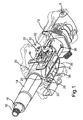
- Fig. 1 is a perspective view obliquely from the front down a steering column for a motor vehicle, which is designed in this case as a passenger car, shown.
- the steering column comprises a steering console 10, which can be fixed on the body side, for example in the region of a corresponding cross member.
- an outer jacket tube 12 for height adjustment or tilt adjustment is pivotally held about a pivot axis S, which in the present case has a substantially tubular hollow cross-section and an inner jacket tube 14 receives in longitudinally adjustable manner described in more detail below.
- a steering shaft 16 is rotatably received, which has at its end facing the driver a corresponding toothing 18, on which the steering wheel of the steering column is fixed.
- the steering bracket 10 To support the steering column, the steering bracket 10 on its side facing away from the pivot axis S or the steering wheel side facing respective, downwardly projecting bearing leg 20, between which the two jacket tubes 12, 14 and the steering shaft 16 are passed.
- this bearing leg 20 In the area of this bearing leg 20, the two jacket tubes 12, 14 and the steering shaft 16 by means of a clamping device 22 with respect to the steering bracket 10 and relative to each other accordingly defined, the basic structure and operation of the particular DE 10 2010 051 880 A1 , the disclosure of which is to be regarded as explicitly included in this regard.
- the hollow cross section of the outer jacket tube 12 has an inner diameter which is at least substantially matched to an outer diameter of the inner jacket tube 14.
- it may be provided - as is the case in this case - between the inner casing tube 14 and the outer casing tube 12 is still a spacer tube element 24 or the like.
- Fig. 4 which shows a partial bottom view of the steering column according to the previous figures, as well as on the basis of Fig. 1
- the outer jacket tube 14 has a recess 26 in the form of a slot over a considerable length range, which recess extends in the axial direction of the jacket tubes 12, 14 or the steering column 10.
- This recess 26 is designed to be open towards a steering wheel side 28 of the outer jacket tube 12.
- the recess 26 has an approximately circular enlargement 30 in cross-section.
- the hollow cross-section of the outer casing tube 12 by means of the clamping device 22 is variable. If, accordingly, the clamping device 22 is released in a manner which will be described in more detail below, then the inner jacket tube 14 with the steering spindle 16 is axially movable relative to the outer jacket tube 12 or the steering console 10, respectively. If the clamping device 22 is in its clamping position in a manner which will be described in more detail below, then the hollow cross-section of the outer jacket tube 12 or the recess 26 is reduced so that the inner jacket tube 14 becomes correspondingly relative to the spacer tube element 24 surrounding it outer jacket tube 12 is fixed.
- the recess 26 in the form of the gap is thus achieved that the longitudinal adjustment of the inner casing tube 14 relative to the outer casing tube 12 after release of the clamping device 22 can be performed very smoothly without the clamping effect is affected in the clamping position accordingly negative. Rather, it is achieved that when unlocking the clamping device 22 by springing the outer jacket tube 12, whereby the recess 26 increases in width accordingly, an enlarged clearance to the inner jacket tube 14 is generated so that it is very easy to move in the outer jacket tube 12.
- the clamping device 22 comprises a clamping bolt 32 which passes through respective outer jacket tube regions 34, 36 adjoining the recess 26. At one end of the clamping bolt 32, a pair of clamping wedges 38, 40 of a clamping wedge device is provided, which are held on each corresponding bearing leg 20 of the steering console 10. On the clamping wedges 38, 40 opposite side, the clamping device 26 has a cam plate 42, which is connected to an actuating lever 44. The cam disc 42 cooperates with a fixed cam disc 46, which is supported on the corresponding bearing leg 20 of the steering console 10.
- the force transmission element 48 which is provided between the corresponding clamping element in the form of the clamping wedge 40 and the outer jacket tube 12 or its jacket tube region 34, is in the present case designed as a clamping plate.
- the use of such a force transmission element 48 has the advantage that optionally an increased frictional force between the clamping device 22 and the outer jacket tube 12 can be provided.
- the clamping wedge 40-without force transmission element 48 lies directly on a flat side on the outer jacket tube 12 and with the opposite wedge-shaped side on a means of an actuating lever 44 transversely to the longitudinal extent of the jacket tubes 38,40 adjustable counter wedge body or clamping wedge 38, and is in a driving connection with the inner jacket tube 14.
- the use of the force transmission element 48 has particular advantages when the steering column is to be used for absorbing impact energy.
- the initiated accident energy goes on in the steering console 10 and from there into the cross member and the car body.
- the power transmission element 48 has been found to be particularly advantageous when a magnesium die-casting alloy is provided as materials for the outer jacket tube 12. As a result, an increased friction can be provided.
- the power transmission element 48 itself is formed in the present case of a steel alloy and includes an axial slot 50 which is penetrated by the clamping bolt 32 of the clamping device. It can be seen that the force transmission element 48 with respect to the corresponding contact surface of the corresponding outer jacket tube portion 34 has an enlarged area, so that at a clamping of the clamping device 22 higher clamping forces acting on the respective clamping wedge 34, 36 transmitted to the outer jacket tube 12 and distribute.
- the force transmission element 48 is coupled in a coupled manner to the inner jacket tube 14 via a driving connection 52 passing through the outer jacket tube 12.
- the power transmission element 48 in the form of the clamping plate on the underside a gripping bar 54 which projects inwardly and is in contact with the inner casing tube 12 through an axial slot 56 within the outer casing tube 12.
- the driving connection 52 between the inner jacket tube 14 and the force transmission element 48 is preferably executed positively and / or cohesively.
- the clamping wedge 40 can be designed for a very simple and on the other hand due to the diversion via the power transmission element 48, both its function to reduce the energy of accident and to lock the longitudinal adjustment of the inner casing tube 14 and the steering column perceive a total.
- the inner jacket tube 14 is moved accordingly with entrainment of the force transmission element 48, whereby a corresponding friction between the associated clamping wedge 40, which is axially fixedly positioned on the outer jacket tube 12, and the force transmission element 48 results.
- a friction-increasing element for example a friction foil or a corresponding coating, which brings the desired friction into effect, is preferably provided between the clamping wedge 40 and the force-transmitting element 48.
- This friction-increasing element can be provided both on the clamping wedge 40 and on the force transmission element 48, that is also at other locations of the clamping device 22.
- the outer jacket tube 12 can be enlarged in its hollow cross-section when loosening the clamping device 22 through the recess 26 so that there are small longitudinal adjustment forces in the unlocked state.
- the hollow cross-section of the outer jacket tube 26 can be reduced by the clamping device 22, so that an optimal fixing of the inner jacket tube 14 relative to the outer jacket tube can be realized.
- a high rigidity and natural frequency of the steering column can be achieved.
- Another advantage is that no additional tolerance compensation between the two jacket tubes 12, 14 of imperative dimensions is required. This also causes minor process fluctuations in the assembly.
Landscapes
- Engineering & Computer Science (AREA)
- Chemical & Material Sciences (AREA)
- Combustion & Propulsion (AREA)
- Transportation (AREA)
- Mechanical Engineering (AREA)
- Steering Controls (AREA)
Description
- Die Erfindung betrifft eine längsverstellbare Lenksäule für einen Kraftwagen, insbesondere einen Personenkraftwagen, gemäß dem Oberbegriff von Patentanspruch 1.
- Eine solche längsverstellbare Lenksäule ist beispielsweise bereits aus der
DE 10 2010 051 880 A1 als bekannt zu entnehmen. Ein inneres Mantelrohr der Lenksäule, welches eine Lenkspindel aufnimmt, ist dabei längsverstellbar in einem äußeren Mantelrohr aufgenommen, welches seinerseits höhenverstellbar an einer rohbauseitig des Kraftwagens befestigbaren Lenkkonsole gehalten ist. Weiterhin umfasst die Lenksäule eine Klemmeinrichtung, mittels welcher das innere Mantelrohr in seiner eingestellten Längsposition relativ zum äußeren Mantelrohr lösbar festlegbar ist. - Bei derartigen, mechanisch verstellbaren Lenksäulen muss die manuell aufzubringende Verstellkraft im gelösten Zustand der Klemmeinrichtung, also wenn das innere Mantelrohr relativ zum äußeren Mantelrohr in seiner Bewegung freigegeben ist, möglichst gering sein, um eine komfortable Verstellung zu gewährleisten. Auf der anderen Seite ist es für eine hohe Steifigkeit bzw. Eigenfrequenz der Lenksäule notwendig, dass der erforderliche Schiebesitz zwischen dem inneren und dem äußeren Mantelrohr mittels der Klemmvorrichtung im verriegelten Zustand möglichst starr ist. Somit ergibt sich ein technischer Konflikt zwischen einer möglichst leichtgängigen Verstellung des inneren zum äußeren Mantelrohr bei gelöster Klemmeinrichtung einerseits und einer möglichst starren Festlegung des inneren Mantelrohrs relativ zum äußeren Mantelrohr bei verriegelter Klemmeinrichtung.
- Dieses Problem verschärft sich außerdem unter der Vorgabe, dass die Lenksäule mit den beiden Mantelrohren zur Aufnahme von unfallbedingter Aufprallenergie ausgebildet sein soll, und außerdem nur ein begrenzter Bauraum zur Verfügung steht. Gerade in diesem Fall sind bisherige Lösungen, bei welchen beispielsweise zwischen den beiden Mantelrohren zum Toleranzausgleich eine Kunststoffeinspritzung vorgesehen ist, welche beispielsweise in der
DE 103 43 685 A1 offenbart ist, nicht geeignet. - Aus der
DE 197 07 067 C1 ist schließlich eine Lenksäuleneinheit für einen Kraftwagen als bekannt zu entnehmen, bei welcher ein Mantelrohr eingesetzt wird, welches einen Nutschlitz aufweist. Dieser Nutschlitz dient zur Verdrehsicherung, sodass das Mantelrohr positionsgenau an einer Befestigungsstelle auf Seiten einer Lenkkonsole fixiert werden kann. - Weiterhin bezieht sich die
US 2006/ 002 80 10 A1 auf eine auf eine Lenksäulenanordnung mit einem äußeren und einem inneren Mantelrohr und einer Klemmvorrichtung. Das äußere Mantelrohr weist einen Längsschlitz auf, über den die Klemmung des inneren Mantelrohrs bewerkstelligt wird. - Aufgabe der vorliegenden Erfindung ist es, eine Lenksäule der eingangs genannten Art zu schaffen, bei welcher das innere Mantelrohr einerseits leichtgängig relativ zum äußeren Mantelrohr längsverstellbar und andererseits starr festlegbar ist.
- Diese Aufgabe wird erfindungsgemäß durch eine Lenksäule mit den Merkmalen des Patentanspruchs 1 gelöst. Vorteilhafte Ausgestaltungen mit zweckmäßigen und nichttrivialen Weiterbildungen der Erfindung sind in den übrigen Patentansprüchen angegeben.
- Um eine Lenksäule der eingangs genannten Art mit einem inneren Mantelrohr zu schaffen, welches einerseits zur Längsverstellung leichtgängig relativ zum äußeren Mantelrohr verstellbar ist, und welches andererseits zur Gewährleistung einer hohen Steifigkeit bzw. Eigenfrequenz der Lenksäule besonders starr am äußeren Mantelteil festlegbar ist, ist es erfindungsgemäß vorgesehen, dass das äußere Mantelrohr zumindest über einen Längenbereich eine Aussparung aufweist, wodurch dessen Hohlquerschnitt mittels der Klemmeinrichtung veränderbar ist. Mit anderen Worten ist es erfindungsgemäß vorgesehen, den Hohlquerschnitt des äußeren Mantelrohrs zumindest über eine Teillänge mit einer Aussparung, beispielsweise in Form eines Längsschlitzes, zu versehen, sodass mittels der Klemmeinrichtung auf einfache Weise dessen Hohlquerschnitt vergrößert bzw. verkleinert werden kann, je nachdem, ob das innere Mantelrohr längsverstellt oder fixiert werden soll.
- Durch das Vorsehen einer derartigen Aussparung kann somit einerseits - bei gelöster Klemmeinrichtung - ein entsprechend aufgeweiteter Hohlquerschnitt des äußeren Mantelrohrs erreicht werden, sodass das innere Mantelrohr leichtgängig relativ zum äußeren Mantelrohr axial verschoben werden kann. Andererseits kann der Hohlquerschnitt mittels der Klemmeinrichtung auf einfache Weise so verkleinert werden, dass sich eine äußerst zuverlässige und starre Festlegung des inneren Mantelrohrs in seiner eingestellten Längsposition relativ zum äußeren Mantelrohr ergibt. Somit kann insgesamt eine Lenksäule hoher Steifigkeit und Eigenfrequenz erzielt werden.
- Weiterhin sieht die Erfindung vor, dass zwischen einem Klemmelement der Klemmeinrichtung und dem äußeren Mantelrohr ein Kraftübertragungselement, insbesondere eine Klemmplatte, vorgesehen ist. Der Vorteil einer derartigen Klemmplatte oder dergleichen Kraftübertragungselement besteht darin, dass dieses auf einfache Weise eine vergrößerte Klemmfläche aufweisen kann, sodass bei einer Klemmung entsprechende Klemmkräfte bis auf das äußere Mantelrohr übertragen werden können. Das Kraftübertragungselement ist dabei über eine das äußere Mantelrohr durchsetzende Mitnahmeverbindung mit dem inneren Mantelrohr bewegungsgekoppelt. Durch diese Mitnahmeverbindung wird das Kraftübertragungselement, insbesondere die Klemmplatte, auf einfache Weise vom inneren Mantelrohr mitgenommen, falls das innere Mantelrohr relativ zum äußeren Mantelrohr verstellt oder aber im Falle einer unfallbedingten Kraftbeaufschlagung das innere teleskopartig in das äußere Mantelrohr geschoben wird.
- Eine weitere vorteilhafte Ausführungsform sieht vor, dass die Aussparung zu einer Lenkradseite des äußeren Mantelrohrs hin offen ausgebildet ist. Durch eine derartige Aussparung des äußeren Mantelrohrs lässt sich dessen Hohlquerschnitt mittels der Klemmeinrichtung auf besonders einfache Weise in dessen Durchmesser variieren, sodass einerseits eine besonders günstige Längsverstellung und andererseits eine äußerst starre Festlegung des inneren Mantelrohrs relativ zum äußeren Mantelrohr erreicht werden kann.
- Dabei hat es sich in weiterer Ausgestaltung der Erfindung als vorteilhaft gezeigt, wenn die Aussparung zumindest im Wesentlichen als in axialer Richtung des äußeren Mantelrohrs verlaufender Schlitz ausgebildet ist. Ein derartiger Schlitz ist fertigungstechnisch besonders einfach herstellbar.
- Weiterhin vorteilhaft ist es, wenn die Klemmeinrichtung eine Klemmkeilvorrichtung umfasst. Eine solche Klemmkeilvorrichtung ermöglicht eine besonders zuverlässige Festlegung des inneren Mantelrohrs relativ zum äußeren Mantelrohr, insbesondere dann, wenn die Lenksäule zur Absorption von Aufprallenergie heranziehbar sein soll.
- Die Mitnahmeverbindung ist dabei vorzugsweise form- und/oder stoffschlüssig ausgeführt, da hierdurch eine besonders zuverlässige Verbindung zwischen dem Kraftübertragungselement und dem inneren Mantelrohr zu erreichen ist.
- Eine weitere vorteilhafte Ausführungsform sieht vor, dass aus dem äußeren Mantelrohr ein Langloch für die Mitnahmeverbindung ausgespart ist. Dieses Langloch kann dabei beispielsweise so gestaltet sein, dass es als Führung für die Mitnahmeverbindung dient.
- In einer weiteren vorteilhaften Ausführungsform ist der Klemmeinrichtung wenigstens ein Reibung erhöhendes Element zugeordnet. Dies kann insbesondere eine entsprechende Reibfolie sein, welche beispielsweise zwischen einem Klemmelement der Klemmeinrichtung und dem äußeren Mantelrohr bzw. dem Kraftübertragungselement angeordnet ist. Alternativ wäre auch eine Beschichtung oder dergleichen denkbar. Hierdurch kann einerseits eine besonders sichere Fixierung des inneren Mantelrohrs relativ zum äußeren Mantelrohr erreicht werden und andererseits die Unfallkraft, welche gegebenenfalls durch die Lenksäule absorbiert werden kann, erhöht werden.
- Schließlich hat es sich als vorteilhaft gezeigt, wenn das äußere Mantelrohr höhenverstellbar an der Lenkkonsole gehalten ist. Hierdurch ergibt sich eine in alle wesentlichen Richtungen verstellbare Lenksäule mit den oben beschriebenen Vorteilen.
- Weitere Vorteile, Merkmale und Einzelheiten der Erfindung ergeben sich aus der nachfolgenden Beschreibung eines bevorzugten Ausführungsbeispiels sowie anhand der Zeichnungen; diese zeigen in:
- Fig. 1
- eine Perspektivansicht von schräg unten auf eine Lenksäule für einen Kraftwagen mit einem eine Lenkspindel aufnehmenden inneren Mantelrohr, welches längsverstellbar in einem an einer rohbauseitig fixierbaren Lenkkonsole gehaltenen, einen Hohlquerschnitt aufweisenden äußeren Mantelrohr aufgenommen ist, und mit einer Klemmeinrichtung, mittels welcher das innere Mantelrohr in seiner eingestellten Längsposition relativ zum äußeren Mantelrohr lösbar festlegbar ist, wobei das äußere Mantelrohr unterseitig über einen erheblichen Längenbereich eine Aussparung in Form eines in Axialrichtung verlaufenden Schlitzes aufweist, welcher zur Lenkradseite des äußeren Mantelrohrs hin offen ausgebildet ist, wodurch der Hohlquerschnitt des äußeren Mantelrohrs mittels der Klemmeinrichtung veränderbar ist;
- Fig. 2
- eine perspektivische Unteransicht auf die Lenksäule gemäß
Fig. 1 bei weggelassener Lenkkonsole und Klemmeinrichtung, sowie bei in Axialrichtung geschnitten dargestelltem äußeren Mantelrohr; - Fig. 3
- eine perspektivische Unteransicht auf die Lenksäule analog zu
Fig. 2 bei weggelassener Lenkkonsole und weggelassener Klemmeinrichtung; und in - Fig. 4
- eine ausschnittsweise und leicht perspektivische Unteransicht auf die Lenkkonsole gemäß den
Fig. 1 bis 3 . - In
Fig. 1 ist in einer Perspektivansicht von schräg vorne unten eine Lenksäule für einen Kraftwagen, der vorliegend als Personenkraftwagen ausgestaltet ist, dargestellt. Die Lenksäule umfasst eine Lenkkonsole 10, welche karosserieseitig beispielsweise im Bereich eines entsprechenden Querträgers festgelegt werden kann. An der Lenkkonsole 10 ist ein äußeres Mantelrohr 12 zur Höhenverstellung bzw. Neigungsverstellung schwenkbar um eine Schwenkachse S gehalten, welches vorliegend im Wesentlichen einen rohrförmigen Hohlquerschnitt aufweist und ein inneres Mantelrohr 14 auf im Weiteren noch näher beschriebene Weise längsverstellbar aufnimmt. Innerhalb des inneren Mantelrohrs 14 ist wiederum eine Lenkspindel 16 drehbar aufgenommen, welche an ihrem dem Fahrzeugführer zugewandten Ende eine entsprechende Verzahnung 18 aufweist, an welcher das Lenkrad der Lenksäule fixierbar ist. - Zur Halterung der Lenksäule weist die Lenkkonsole 10 an ihrer der Schwenkachse S abgewandten bzw. dem Lenkrad zugewandten Seite jeweilige, nach unten abstehende Lagerschenkel 20 auf, zwischen welchen die beiden Mantelrohre 12, 14 bzw. die Lenkspindel 16 hindurchgeführt sind. Im Bereich dieser Lagerschenkel 20 sind die beiden Mantelrohre 12, 14 bzw. die Lenkspindel 16 mittels einer Klemmeinrichtung 22 in Bezug auf die Lenkkonsole 10 bzw. relativ zueinander entsprechend festlegbar, deren prinzipieller Aufbau und deren Funktionsweise insbesondere der
DE 10 2010 051 880 A1 , deren Offenbarungsgehalt diesbezüglich als explizit mit umfasst gelten soll, zu entnehmen ist. - Wie aus den
Fig. 2 und3 zu erkennen ist, weist der Hohlquerschnitt des äußeren Mantelrohrs 12 einen Innendurchmesser auf, welcher zumindest im Wesentlichen auf einen Außendurchmesser des inneren Mantelrohrs 14 abgestimmt ist. Gegebenenfalls kann dabei - wie dies im vorliegenden Fall gegeben ist - zwischen dem inneren Mantelrohr 14 und dem äußeren Mantelrohr 12 noch ein Distanz-Rohrelement 24 oder dergleichen vorgesehen sein. - Des Weiteren ist insbesondere aus
Fig. 4 , welche eine ausschnittsweise Unteransicht auf die Lenksäule gemäß den vorherigen Figuren zeigt, sowie anhand vonFig. 1 erkennbar, dass das äußere Mantelrohr 14 über einen erheblichen Längenbereich eine Aussparung 26 in Form eines Schlitzes aufweist, welcher sich in Axialrichtung der Mantelrohre 12, 14 bzw. der Lenksäule 10 erstreckt. Diese Aussparung 26 ist dabei zu einer Lenkradseite 28 des äußeren Mantelrohrs 12 hin offen ausgebildet. Am gegenüberliegenden Ende weist die Aussparung 26 eine im Querschnitt etwa kreisförmige Vergrößerung 30 auf. - Durch die Aussparung 26 kann erreicht werden, dass der Hohlquerschnitt des äußeren Mantelrohrs 12 mittels der Klemmeinrichtung 22 veränderbar ist. Wird demzufolge die Klemmeinrichtung 22 auf im Weiteren noch näher beschriebene Weise gelöst, so ist das innere Mantelrohr 14 mit der Lenkspindel 16 relativ zum äußeren Mantelrohr 12 bzw. zur Lenkkonsole 10 axial beweglich längsverstellbar. Befindet sich die Klemmeinrichtung 22 auf im Weiteren noch näher beschriebene Weise hingegen in ihrer Klemmstellung, so wird der Hohlquerschnitt des äußeren Mantelrohrs 12 bzw. die Aussparung 26 so verkleinert, dass hierdurch das innere Mantelrohr 14 mit dem dieses umgebenden Distanz-Rohrelement 24 entsprechend relativ zum äußeren Mantelrohr 12 fixiert ist.
- Durch die Aussparung 26 in Form des Spalts wird somit erreicht, dass die Längsverstellung des inneren Mantelrohrs 14 relativ zum äußeren Mantelrohr 12 nach dem Lösen der Klemmeinrichtung 22 besonders leichtgängig durchgeführt werden kann, ohne dass die Klemmwirkung in der Klemmstellung entsprechend negativ beeinflusst wird. Vielmehr wird erreicht, dass beim Entriegeln der Klemmeinrichtung 22 durch Auffederung des äußeren Mantelrohrs 12, wodurch sich die Aussparung 26 entsprechend in ihrer Breite vergrößert, ein vergrößertes Spiel zum inneren Mantelrohr 14 erzeugt wird, sodass diese im äußeren Mantelrohr 12 sehr leicht verschiebbar ist.
- Im verriegelten Zustand der Klemmeinrichtung 22 wird die Breite der Aussparung 26 infolge der ausgeübten Klemmkraft hingegen so verkleinert, sodass das Spiel aufgehoben wird und die arretierende Verspannung zwischen den beiden Mantelrohren 12, 14 bzw. Mantelrohrteilen erfolgt.
- Die Klemmeinrichtung 22 umfasst einen Klemmbolzen 32, welcher jeweilige, an die Aussparung 26 angrenzende äußere Mantelrohrbereiche 34, 36 durchsetzt. Am einen Ende des Klemmbolzens 32 ist dabei ein Paar von Klemmkeilen 38, 40 einer Klemmkeilvorrichtung vorgesehen, welche am jeweils korrespondierenden Lagerschenkel 20 der Lenkkonsole 10 gehalten sind. Auf der den Klemmkeilen 38, 40 gegenüberliegenden Seite weist die Klemmeinrichtung 26 eine Nockenscheibe 42 auf, welche mit einem Betätigungshebel 44 verbunden ist. Die Nockenscheibe 42 wirkt dabei mit einer feststehenden Nockenscheibe 46 zusammen, welche sich am korrespondierenden Lagerschenkel 20 der Lenkkonsole 10 abstützt. Durch entsprechendes Verschwenken des Betätigungshebels 44 nach unten bzw. nach oben wird somit die Nockenscheibe 42 relativ zur Nockenscheibe 46 verdreht, wodurch sich eine axiale Distanz zwischen der Nockenscheibe 46 und den Klemmkeilen 38, 40 entsprechend vergrößert oder verkleinert. Mit anderen Worten sind die Klemmkeile 38, 40 quer zur Längserstreckung der Mantelrohre 12, 14 verstellbar.
- Da der Klemmkeil 40 unter Vermittlung eines im Weiteren noch näher erläuterten Kraftübertragungselements 48 im mittelbaren Kontakt mit dem korrespondierenden äußeren Mantelrohrbereich 34 des äußeren Mantelrohrs 12 steht, bewirkt eine Betätigung des Betätigungshebels 44 entsprechend eine Veränderung der Breite der Aussparung 26 bzw. des Abstands der beiden äußeren Mantelrohrbereiche 34, 36, und somit ein Klemmen oder Lösen des inneren Mantelrohrs 14 in Bezug auf das äußere Mantelrohr 12.
- Das Kraftübertragungselement 48, das zwischen dem entsprechenden Klemmelement in Form des Klemmkeils 40 und dem äußeren Mantelrohr 12 bzw. dessen Mantelrohrbereich 34 vorgesehen ist, ist vorliegend als Klemmplatte ausgebildet. Im Gegensatz zu einer unmittelbaren Anlage des Klemmkeils 40 an dem äußeren Mantelrohrbereich 34, welches ebenso denkbar wäre, hat der Einsatz eines derartigen Kraftübertragungselements 48 den Vorteil, dass gegebenenfalls eine erhöhte Reibkraft zwischen der Klemmeinrichtung 22 und dem äußeren Mantelrohr 12 bereitgestellt werden kann.
- Wird eine Ausgestaltung ohne Kraftübertragungselement 48 gewählt, so liegt der Klemmkeil 40 - ohne Kraftübertragungselement 48 - unmittelbar mit einer flachen Seite am äußeren Mantelrohr 12 und mit der gegenüberliegenden keilförmigen Seite an einem mittels eines Betätigungshebels 44 quer zur Längserstreckung der Mantelrohre 38,40 verstellbaren Gegenkeilkörper bzw. Klemmkeil 38 an, und steht in einer Mitnahmeverbindung mit dem inneren Mantelrohr 14 steht.
- Der Einsatz des Kraftübertragungselements 48 hat insbesondere Vorteile, wenn die Lenksäule zur Absorption von Aufprallenergie herangezogen werden soll. Bei einer unfallbedingten Krafteinleitung und Relativbewegung der Mantelrohre 12, 14 schleift der Klemmkeil 40 dann nicht entlang des äußeren Mantelrohrs 12, sondern vielmehr entlang des Kraftübertragungselements 48, wodurch über dieses die eingeleitete Unfallenergie in die Klemmeinrichtung 22 eingeleitet und mittels der Klemmkeilwirkung abgebaut wird. Die eingeleitete Unfallenergie geht dabei weiter in die Lenkkonsole 10 und von dort in den Querträger bzw. die Kraftwagenkarosserie. Das Kraftübertragungselement 48 hat sich dabei insbesondere als vorteilhaft gezeigt, wenn als Werkstoffe für das äußere Mantelrohr 12 eine Magnesium-Druckgusslegierung vorgesehen wird. Hierdurch kann eine erhöhte Reibung bereitgestellt werden.
- Das Kraftübertragungselement 48 selbst ist im vorliegenden Fall aus einer Stahllegierung gebildet und umfasst ein axiales Langloch 50, welches vom Klemmbolzen 32 der Klemmeinrichtung durchsetzt wird. Dabei ist erkennbar, dass das Kraftübertragungselement 48 gegenüber der korrespondierenden Anlagefläche des entsprechenden äußeren Mantelrohrbereichs 34 eine vergrößerte Fläche aufweist, sodass sich bei einer Klemmung der Klemmeinrichtung 22 höhere Klemmkräfte, die über den jeweiligen Klemmkeil 34, 36 wirken, auf das äußere Mantelrohr 12 übertragen und verteilen lassen.
- Insbesondere aus den
Fig. 2 und3 ist des Weiteren erkennbar, dass das Kraftübertragungselement 48 über eine das äußere Mantelrohr 12 durchsetzende Mitnahmeverbindung 52 mit dem inneren Mantelrohr 14 bewegungsgekoppelt ist. Zur Herstellung dieser Mitnahmeverbindung 52 weist das Kraftübertragungselement 48 in Form der Klemmplatte unterseitig eine Greifleiste 54 auf, die nach innen abkragt und durch ein axiales Langloch 56 innerhalb des äußeren Mantelrohrs 12 hindurch mit dem inneren Mantelrohr 12 in Kontakt steht. Die Mitnahmeverbindung 52 zwischen dem inneren Mantelrohr 14 und dem Kraftübertragungselement 48 ist dabei vorzugsweise form- und/oder stoffschlüssig ausgeführt. Bei der Abkopplung des entsprechenden Klemmkeils 40 vom äußeren Mantel 12, um hierdurch eine unmittelbare Anlage an diesem zu vermeiden, kann der Klemmkeil 40 zum einen sehr einfach ausgebildet sein und zum anderen aufgrund der Umleitung über das Kraftübertragungselement 48 sowohl seine Funktion zum Abbau von Unfallenergie als auch zur Arretierung der Längsverstellung des inneren Mantelrohrs 14 bzw. der Lenksäule insgesamt wahrnehmen. - Bei einer derartigen unfallbedingten Kraftbeaufschlagung wird das innere Mantelrohr 14 unter Mitnahme des Kraftübertragungselements 48 entsprechend verschoben, wodurch sich eine entsprechende Reibung zwischen dem zugehörigen Klemmkeil 40, der axial fest am äußeren Mantelrohr 12 positioniert ist, und dem Kraftübertragungselement 48 ergibt. Dabei wird bevorzugter Weise zwischen dem Klemmkeil 40 und dem Kraftübertragungselement 48 ein Reibung erhöhendes Element, beispielsweise eine Reibfolie oder eine entsprechende Beschichtung, die die gewünschte Reibung zur Geltung bringt, vorgesehen. Dieses Reibung erhöhende Element kann dabei sowohl am Klemmkeil 40 als auch am Kraftübertragungselement 48, also auch an anderen Stellen der Klemmeinrichtung 22 vorgesehen sein.
- Insgesamt ist somit erkennbar, dass durch die Aussparung 26 vorliegend das äußere Mantelrohr 12 in seinem Hohlquerschnitt beim Lösen der Klemmeinrichtung 22 so vergrößert werden kann, so dass sich geringe Längsverstellkräfte im entriegelten Zustand ergeben. Gleichzeitig kann durch die Klemmeinrichtung 22 der Hohlquerschnitt des äußeren Mantelrohrs 12 infolge des Vorsehens der Aussparung 26 so verringert werden, so dass sich eine optimale Festlegung des inneren Mantelrohrs 14 relativ zum äußeren Mantelrohr realisieren lässt. Hierdurch kann eine hohe Steifigkeit und Eigenfrequenz der Lenksäule erreicht werden. Ein weiterer Vorteil besteht darin, dass kein zusätzlicher Toleranzausgleich zwischen den beiden Mantelrohren 12, 14 zwingender Maßen erforderlich ist. Dies bewirkt zudem geringe Prozessschwankungen in der Montage.
Claims (9)
- Lenksäule für einen Kraftwagen, mit einem eine Lenkspindel (16) aufnehmenden inneren Mantelrohr (14), welches längsverstellbar in einem an einer Lenkkonsole (10) gehaltenen, einen Hohlquerschnitt aufweisenden äußeren Mantelrohr (12) aufgenommen ist, und mit einer Klemmeinrichtung (22), mittels welcher das innere Mantelrohr (14) in seiner eingestellten Längsposition relativ zum äußeren Mantelrohr (12) lösbar festlegbar ist, wobei
das äußere Mantelrohr (12) zumindest über einen Längenbereich eine Aussparung (26) aufweist, wodurch dessen Hohlquerschnitt mittels der Klemmeinrichtung (22) veränderbar ist, dadurch gekennzeichnet, dass zwischen einem Klemmelement (40) der Klemmeinrichtung (22) und dem äußeren Mantelrohr (12) ein Kraftübertragungselement (48) vorgesehen ist, welches über eine das äußere Mantelrohr (12) durchsetzende Mitnahmeverbindung (52) mit dem inneren Mantelrohr (14) bewegungsgekoppelt ist. - Lenksäule nach Anspruch 1,
dadurch gekennzeichnet, dass
das Kraftübertragungselement (48) eine Klemmplatte ist. - Lenksäule nach einem der Ansprüche 1 oder 2,
dadurch gekennzeichnet, dass
die Aussparung (26) zu einer Lenkradseite (28) des äußeren Mantelrohrs (12) hin offen ausgebildet ist. - Lenksäule nach einem der vorhergehenden Ansprüche,
dadurch gekennzeichnet, dass
die Aussparung (26) zumindest im Wesentlichen als in Axialrichtung des äußeren Mantelrohres (12) verlaufender Schlitz ausgebildet ist. - Lenksäule nach einem der vorhergehenden Ansprüche,
dadurch gekennzeichnet, dass
die Klemmeinrichtung (22) eine Keilklemmvorrichtung umfasst. - Lenksäule nach einem der vorhergehenden Ansprüche,
dadurch gekennzeichnet, dass
das Kraftübertragungselement (48) über die Mitnahmeverbindung (52) form-und/oder stoffschlüssig mit dem inneren Mantelrohr (14) verbunden ist. - Lenksäule nach einem der vorhergehenden Ansprüche,
dadurch gekennzeichnet, dass
aus dem äußeren Mantelrohr (12) ein Langloch (56) für die Mitnahmeverbindung (52) ausgespart ist. - Lenksäule nach einem der vorhergehenden Ansprüche,
dadurch gekennzeichnet, dass
der Klemmeinrichtung (22) wenigstens ein Reibung erhöhendes Element zugeordnet ist. - Lenksäule nach einem der vorhergehenden Ansprüche,
dadurch gekennzeichnet, dass
das äußere Mantelrohr (12) höhenverstellbar an der Lenkkonsole gehalten ist.
Applications Claiming Priority (2)
| Application Number | Priority Date | Filing Date | Title |
|---|---|---|---|
| DE102012008836A DE102012008836A1 (de) | 2012-04-28 | 2012-04-28 | Lenksäule für einen Kraftwagen |
| PCT/EP2013/000343 WO2013159846A1 (de) | 2012-04-28 | 2013-02-05 | Lenksäule für einen kraftwagen |
Publications (2)
| Publication Number | Publication Date |
|---|---|
| EP2841323A1 EP2841323A1 (de) | 2015-03-04 |
| EP2841323B1 true EP2841323B1 (de) | 2016-04-27 |
Family
ID=47678701
Family Applications (1)
| Application Number | Title | Priority Date | Filing Date |
|---|---|---|---|
| EP13702925.2A Active EP2841323B1 (de) | 2012-04-28 | 2013-02-05 | Lenksäule für einen kraftwagen |
Country Status (5)
| Country | Link |
|---|---|
| US (1) | US9266554B2 (de) |
| EP (1) | EP2841323B1 (de) |
| CN (1) | CN104271429B (de) |
| DE (1) | DE102012008836A1 (de) |
| WO (1) | WO2013159846A1 (de) |
Families Citing this family (9)
| Publication number | Priority date | Publication date | Assignee | Title |
|---|---|---|---|---|
| DE102013016534B3 (de) * | 2013-10-07 | 2014-12-24 | Daimler Ag | Lenksäulenanordnung für einen Kraftwagen |
| JP6351009B2 (ja) * | 2014-03-24 | 2018-07-04 | 株式会社ジェイテクト | ステアリング装置 |
| JP6270141B2 (ja) * | 2014-03-24 | 2018-01-31 | 株式会社ジェイテクト | ステアリング装置 |
| EP3395647B1 (de) * | 2016-02-04 | 2020-10-21 | NSK Ltd. | Lenkvorrichtung |
| DE102016202465B4 (de) * | 2016-02-18 | 2019-05-29 | Thyssenkrupp Ag | Motorisch verstellbare Lenksäule für ein Kraftfahrzeug |
| DE102016011167A1 (de) | 2016-09-16 | 2017-03-30 | Daimler Ag | Lenksäule für einen Kraftwagen |
| DE102016011172A1 (de) | 2016-09-16 | 2017-03-30 | Daimler Ag | Lenksäule für einen Kraftwagen |
| DE102016011171A1 (de) | 2016-09-16 | 2017-03-30 | Daimler Ag | Lenksäule für einen Kraftwagen |
| US20180086378A1 (en) * | 2016-09-27 | 2018-03-29 | Steering Solutions Ip Holding Corporation | Position detection system for a retractable steering column |
Family Cites Families (17)
| Publication number | Priority date | Publication date | Assignee | Title |
|---|---|---|---|---|
| GB2116496B (en) * | 1982-03-09 | 1985-08-14 | Gen Motors Ltd | Steering column mounting assemblies |
| DE19707067C1 (de) | 1997-02-22 | 1998-06-25 | Kostal Leopold Gmbh & Co Kg | Lenksäuleneinheit für einen Kraftwagen |
| DE60133331T3 (de) * | 2000-02-15 | 2012-12-06 | Nsk Ltd. | Lenkung für ein Automobil |
| JP3738200B2 (ja) * | 2001-06-27 | 2006-01-25 | 光洋精工株式会社 | 衝撃吸収ステアリング装置 |
| JPWO2004043766A1 (ja) * | 2002-11-11 | 2006-03-09 | 日本精工株式会社 | 車両用ステアリング装置 |
| DE10343685B4 (de) | 2003-09-20 | 2009-03-19 | Daimler Ag | Fahrzeuglenksäulenanordnung |
| JP4609203B2 (ja) * | 2004-08-05 | 2011-01-12 | 日本精工株式会社 | ステアリングコラム装置 |
| DE102004051060B3 (de) * | 2004-10-19 | 2006-01-26 | Thyssenkrupp Presta Ag | Verstellbare Lenksäule eines Kraftfahrzeuges |
| DE102007002091B4 (de) * | 2007-01-09 | 2010-09-09 | Thyssenkrupp Technologies Ag | Lenksäule mit Crasheinrichtung |
| DE102007003091B3 (de) * | 2007-01-16 | 2008-08-07 | Thyssenkrupp Presta Ag | Verstellbare Lenksäule für ein Kraftfahrzeug |
| GB0714161D0 (en) * | 2007-07-20 | 2007-08-29 | Trw Ltd | Steering column assembly |
| DE102007053672A1 (de) * | 2007-11-10 | 2009-05-20 | Daimler Ag | Lenksäulenanordnung für Kraftwagen |
| US8979128B2 (en) * | 2009-05-29 | 2015-03-17 | Steering Solutions Ip Holding Corporation | Collapsible steering column assembly |
| CN102666249B (zh) | 2009-11-21 | 2015-05-13 | 戴姆勒股份公司 | 机动车的转向柱组件 |
| JP5662115B2 (ja) * | 2010-01-20 | 2015-01-28 | 株式会社山田製作所 | ステアリング装置 |
| JP5788829B2 (ja) * | 2012-04-06 | 2015-10-07 | 株式会社山田製作所 | ステアリング装置 |
| JP2014058200A (ja) * | 2012-09-14 | 2014-04-03 | Yamada Seisakusho Co Ltd | ステアリング装置 |
-
2012
- 2012-04-28 DE DE102012008836A patent/DE102012008836A1/de not_active Withdrawn
-
2013
- 2013-02-05 WO PCT/EP2013/000343 patent/WO2013159846A1/de not_active Ceased
- 2013-02-05 US US14/397,242 patent/US9266554B2/en active Active
- 2013-02-05 EP EP13702925.2A patent/EP2841323B1/de active Active
- 2013-02-05 CN CN201380022309.4A patent/CN104271429B/zh active Active
Also Published As
| Publication number | Publication date |
|---|---|
| CN104271429A (zh) | 2015-01-07 |
| US9266554B2 (en) | 2016-02-23 |
| WO2013159846A1 (de) | 2013-10-31 |
| DE102012008836A1 (de) | 2013-10-31 |
| CN104271429B (zh) | 2016-10-12 |
| EP2841323A1 (de) | 2015-03-04 |
| US20150076804A1 (en) | 2015-03-19 |
Similar Documents
| Publication | Publication Date | Title |
|---|---|---|
| WO2013159846A1 (de) | Lenksäule für einen kraftwagen | |
| DE102007002091B4 (de) | Lenksäule mit Crasheinrichtung | |
| DE102016202465B4 (de) | Motorisch verstellbare Lenksäule für ein Kraftfahrzeug | |
| DE102011054598B3 (de) | Lenkspindellagereinheit zur drehbaren Lagerung einer Lenkspindel | |
| EP4222042B1 (de) | Lenksäule für ein kraftfahrzeug | |
| DE102009038317B4 (de) | Verstellbare Lenksäule für ein Kraftfahrzeug | |
| DE102017223469A1 (de) | Motorisch verstellbare Lenksäule für ein Kraftfahrzeug | |
| EP2768712B1 (de) | Lenkspindellagereinheit zur drehbaren lagerung einer lenkspindel | |
| DE102011054597A1 (de) | Lenkspindellagereinheit | |
| EP3908499B1 (de) | Lenksäule für ein kraftfahrzeug | |
| DE102015000029A1 (de) | Lenksäule mit adaptierbarer Schwenklagerung | |
| WO2013124024A1 (de) | Lenksäule für ein kraftfahrzeug mit einem tragteil | |
| DE102017223470A1 (de) | Motorisch verstellbare Lenksäule für ein Kraftfahrzeug | |
| DE112019005339T5 (de) | Lenksäulenvorrichtung | |
| EP2501601B1 (de) | Lenksäulenanordnung für einen kraftwagen | |
| EP3911553B1 (de) | Lenksäule für ein kraftfahrzeug | |
| EP4299414A1 (de) | Lenksäule für ein kraftfahrzeug | |
| DE102004020048A1 (de) | Sicherheitslenksäule für ein Kraftfahrzeug | |
| EP2205475B1 (de) | Lenksäulenanordnung für kraftwagen | |
| DE102023104998B4 (de) | Längenverstellbare Bedieneinheit | |
| EP1873004A2 (de) | Kraftfahrzeugsitz mit einer Rückenlehne, die automatisch von der Gebrauchsstellung in die Nichtgebrauchsstellung verschwenkbar ist | |
| EP4161816B1 (de) | Lenksäule für ein kraftfahrzeug | |
| EP4279357A1 (de) | Lenksystem für ein kraftfahrzeug | |
| DE102009041840B3 (de) | Vorrichtung zum Verstellen einer Kopfstütze | |
| DE102021200946A1 (de) | Lenksäule für ein Kraftfahrzeug |
Legal Events
| Date | Code | Title | Description |
|---|---|---|---|
| PUAI | Public reference made under article 153(3) epc to a published international application that has entered the european phase |
Free format text: ORIGINAL CODE: 0009012 |
|
| 17P | Request for examination filed |
Effective date: 20141011 |
|
| AK | Designated contracting states |
Kind code of ref document: A1 Designated state(s): AL AT BE BG CH CY CZ DE DK EE ES FI FR GB GR HR HU IE IS IT LI LT LU LV MC MK MT NL NO PL PT RO RS SE SI SK SM TR |
|
| AX | Request for extension of the european patent |
Extension state: BA ME |
|
| RIN1 | Information on inventor provided before grant (corrected) |
Inventor name: SCHULZE, STEFFEN Inventor name: HEBENSTREIT, AXEL Inventor name: SCHWIEGER, MARCO Inventor name: KITTLER, HOLGER Inventor name: MAAK, JAN Inventor name: HARMS, TORSTEN Inventor name: NIEMOELLER, JUERGEN Inventor name: HANSEN, DETLEF |
|
| DAX | Request for extension of the european patent (deleted) | ||
| GRAP | Despatch of communication of intention to grant a patent |
Free format text: ORIGINAL CODE: EPIDOSNIGR1 |
|
| INTG | Intention to grant announced |
Effective date: 20151106 |
|
| GRAS | Grant fee paid |
Free format text: ORIGINAL CODE: EPIDOSNIGR3 |
|
| GRAA | (expected) grant |
Free format text: ORIGINAL CODE: 0009210 |
|
| AK | Designated contracting states |
Kind code of ref document: B1 Designated state(s): AL AT BE BG CH CY CZ DE DK EE ES FI FR GB GR HR HU IE IS IT LI LT LU LV MC MK MT NL NO PL PT RO RS SE SI SK SM TR |
|
| REG | Reference to a national code |
Ref country code: GB Ref legal event code: FG4D Free format text: NOT ENGLISH |
|
| REG | Reference to a national code |
Ref country code: CH Ref legal event code: EP |
|
| REG | Reference to a national code |
Ref country code: AT Ref legal event code: REF Ref document number: 794417 Country of ref document: AT Kind code of ref document: T Effective date: 20160515 |
|
| REG | Reference to a national code |
Ref country code: IE Ref legal event code: FG4D Free format text: LANGUAGE OF EP DOCUMENT: GERMAN |
|
| REG | Reference to a national code |
Ref country code: DE Ref legal event code: R096 Ref document number: 502013002778 Country of ref document: DE |
|
| REG | Reference to a national code |
Ref country code: LT Ref legal event code: MG4D |
|
| REG | Reference to a national code |
Ref country code: NL Ref legal event code: MP Effective date: 20160427 |
|
| PG25 | Lapsed in a contracting state [announced via postgrant information from national office to epo] |
Ref country code: NL Free format text: LAPSE BECAUSE OF FAILURE TO SUBMIT A TRANSLATION OF THE DESCRIPTION OR TO PAY THE FEE WITHIN THE PRESCRIBED TIME-LIMIT Effective date: 20160427 |
|
| PG25 | Lapsed in a contracting state [announced via postgrant information from national office to epo] |
Ref country code: NO Free format text: LAPSE BECAUSE OF FAILURE TO SUBMIT A TRANSLATION OF THE DESCRIPTION OR TO PAY THE FEE WITHIN THE PRESCRIBED TIME-LIMIT Effective date: 20160727 Ref country code: PL Free format text: LAPSE BECAUSE OF FAILURE TO SUBMIT A TRANSLATION OF THE DESCRIPTION OR TO PAY THE FEE WITHIN THE PRESCRIBED TIME-LIMIT Effective date: 20160427 Ref country code: LT Free format text: LAPSE BECAUSE OF FAILURE TO SUBMIT A TRANSLATION OF THE DESCRIPTION OR TO PAY THE FEE WITHIN THE PRESCRIBED TIME-LIMIT Effective date: 20160427 Ref country code: FI Free format text: LAPSE BECAUSE OF FAILURE TO SUBMIT A TRANSLATION OF THE DESCRIPTION OR TO PAY THE FEE WITHIN THE PRESCRIBED TIME-LIMIT Effective date: 20160427 |
|
| PG25 | Lapsed in a contracting state [announced via postgrant information from national office to epo] |
Ref country code: HR Free format text: LAPSE BECAUSE OF FAILURE TO SUBMIT A TRANSLATION OF THE DESCRIPTION OR TO PAY THE FEE WITHIN THE PRESCRIBED TIME-LIMIT Effective date: 20160427 Ref country code: SE Free format text: LAPSE BECAUSE OF FAILURE TO SUBMIT A TRANSLATION OF THE DESCRIPTION OR TO PAY THE FEE WITHIN THE PRESCRIBED TIME-LIMIT Effective date: 20160427 Ref country code: RS Free format text: LAPSE BECAUSE OF FAILURE TO SUBMIT A TRANSLATION OF THE DESCRIPTION OR TO PAY THE FEE WITHIN THE PRESCRIBED TIME-LIMIT Effective date: 20160427 Ref country code: ES Free format text: LAPSE BECAUSE OF FAILURE TO SUBMIT A TRANSLATION OF THE DESCRIPTION OR TO PAY THE FEE WITHIN THE PRESCRIBED TIME-LIMIT Effective date: 20160427 Ref country code: PT Free format text: LAPSE BECAUSE OF FAILURE TO SUBMIT A TRANSLATION OF THE DESCRIPTION OR TO PAY THE FEE WITHIN THE PRESCRIBED TIME-LIMIT Effective date: 20160829 Ref country code: LV Free format text: LAPSE BECAUSE OF FAILURE TO SUBMIT A TRANSLATION OF THE DESCRIPTION OR TO PAY THE FEE WITHIN THE PRESCRIBED TIME-LIMIT Effective date: 20160427 Ref country code: GR Free format text: LAPSE BECAUSE OF FAILURE TO SUBMIT A TRANSLATION OF THE DESCRIPTION OR TO PAY THE FEE WITHIN THE PRESCRIBED TIME-LIMIT Effective date: 20160728 |
|
| PG25 | Lapsed in a contracting state [announced via postgrant information from national office to epo] |
Ref country code: IT Free format text: LAPSE BECAUSE OF FAILURE TO SUBMIT A TRANSLATION OF THE DESCRIPTION OR TO PAY THE FEE WITHIN THE PRESCRIBED TIME-LIMIT Effective date: 20160427 |
|
| REG | Reference to a national code |
Ref country code: DE Ref legal event code: R097 Ref document number: 502013002778 Country of ref document: DE |
|
| PG25 | Lapsed in a contracting state [announced via postgrant information from national office to epo] |
Ref country code: SK Free format text: LAPSE BECAUSE OF FAILURE TO SUBMIT A TRANSLATION OF THE DESCRIPTION OR TO PAY THE FEE WITHIN THE PRESCRIBED TIME-LIMIT Effective date: 20160427 Ref country code: RO Free format text: LAPSE BECAUSE OF FAILURE TO SUBMIT A TRANSLATION OF THE DESCRIPTION OR TO PAY THE FEE WITHIN THE PRESCRIBED TIME-LIMIT Effective date: 20160427 Ref country code: DK Free format text: LAPSE BECAUSE OF FAILURE TO SUBMIT A TRANSLATION OF THE DESCRIPTION OR TO PAY THE FEE WITHIN THE PRESCRIBED TIME-LIMIT Effective date: 20160427 Ref country code: CZ Free format text: LAPSE BECAUSE OF FAILURE TO SUBMIT A TRANSLATION OF THE DESCRIPTION OR TO PAY THE FEE WITHIN THE PRESCRIBED TIME-LIMIT Effective date: 20160427 Ref country code: EE Free format text: LAPSE BECAUSE OF FAILURE TO SUBMIT A TRANSLATION OF THE DESCRIPTION OR TO PAY THE FEE WITHIN THE PRESCRIBED TIME-LIMIT Effective date: 20160427 |
|
| REG | Reference to a national code |
Ref country code: FR Ref legal event code: PLFP Year of fee payment: 5 |
|
| PG25 | Lapsed in a contracting state [announced via postgrant information from national office to epo] |
Ref country code: SM Free format text: LAPSE BECAUSE OF FAILURE TO SUBMIT A TRANSLATION OF THE DESCRIPTION OR TO PAY THE FEE WITHIN THE PRESCRIBED TIME-LIMIT Effective date: 20160427 |
|
| PLBE | No opposition filed within time limit |
Free format text: ORIGINAL CODE: 0009261 |
|
| STAA | Information on the status of an ep patent application or granted ep patent |
Free format text: STATUS: NO OPPOSITION FILED WITHIN TIME LIMIT |
|
| 26N | No opposition filed |
Effective date: 20170130 |
|
| PG25 | Lapsed in a contracting state [announced via postgrant information from national office to epo] |
Ref country code: BE Free format text: LAPSE BECAUSE OF NON-PAYMENT OF DUE FEES Effective date: 20170228 Ref country code: SI Free format text: LAPSE BECAUSE OF FAILURE TO SUBMIT A TRANSLATION OF THE DESCRIPTION OR TO PAY THE FEE WITHIN THE PRESCRIBED TIME-LIMIT Effective date: 20160427 |
|
| PG25 | Lapsed in a contracting state [announced via postgrant information from national office to epo] |
Ref country code: MC Free format text: LAPSE BECAUSE OF FAILURE TO SUBMIT A TRANSLATION OF THE DESCRIPTION OR TO PAY THE FEE WITHIN THE PRESCRIBED TIME-LIMIT Effective date: 20160427 |
|
| REG | Reference to a national code |
Ref country code: CH Ref legal event code: PL |
|
| PG25 | Lapsed in a contracting state [announced via postgrant information from national office to epo] |
Ref country code: LI Free format text: LAPSE BECAUSE OF NON-PAYMENT OF DUE FEES Effective date: 20170228 Ref country code: CH Free format text: LAPSE BECAUSE OF NON-PAYMENT OF DUE FEES Effective date: 20170228 |
|
| REG | Reference to a national code |
Ref country code: IE Ref legal event code: MM4A |
|
| PG25 | Lapsed in a contracting state [announced via postgrant information from national office to epo] |
Ref country code: LU Free format text: LAPSE BECAUSE OF NON-PAYMENT OF DUE FEES Effective date: 20170205 |
|
| REG | Reference to a national code |
Ref country code: BE Ref legal event code: MM Effective date: 20170228 |
|
| REG | Reference to a national code |
Ref country code: FR Ref legal event code: PLFP Year of fee payment: 6 |
|
| PG25 | Lapsed in a contracting state [announced via postgrant information from national office to epo] |
Ref country code: IE Free format text: LAPSE BECAUSE OF NON-PAYMENT OF DUE FEES Effective date: 20170205 |
|
| PG25 | Lapsed in a contracting state [announced via postgrant information from national office to epo] |
Ref country code: MT Free format text: LAPSE BECAUSE OF FAILURE TO SUBMIT A TRANSLATION OF THE DESCRIPTION OR TO PAY THE FEE WITHIN THE PRESCRIBED TIME-LIMIT Effective date: 20160427 |
|
| PG25 | Lapsed in a contracting state [announced via postgrant information from national office to epo] |
Ref country code: AL Free format text: LAPSE BECAUSE OF FAILURE TO SUBMIT A TRANSLATION OF THE DESCRIPTION OR TO PAY THE FEE WITHIN THE PRESCRIBED TIME-LIMIT Effective date: 20160427 |
|
| REG | Reference to a national code |
Ref country code: AT Ref legal event code: MM01 Ref document number: 794417 Country of ref document: AT Kind code of ref document: T Effective date: 20180205 |
|
| PG25 | Lapsed in a contracting state [announced via postgrant information from national office to epo] |
Ref country code: AT Free format text: LAPSE BECAUSE OF NON-PAYMENT OF DUE FEES Effective date: 20180205 |
|
| PG25 | Lapsed in a contracting state [announced via postgrant information from national office to epo] |
Ref country code: HU Free format text: LAPSE BECAUSE OF FAILURE TO SUBMIT A TRANSLATION OF THE DESCRIPTION OR TO PAY THE FEE WITHIN THE PRESCRIBED TIME-LIMIT; INVALID AB INITIO Effective date: 20130205 |
|
| PG25 | Lapsed in a contracting state [announced via postgrant information from national office to epo] |
Ref country code: BG Free format text: LAPSE BECAUSE OF FAILURE TO SUBMIT A TRANSLATION OF THE DESCRIPTION OR TO PAY THE FEE WITHIN THE PRESCRIBED TIME-LIMIT Effective date: 20160427 |
|
| PG25 | Lapsed in a contracting state [announced via postgrant information from national office to epo] |
Ref country code: CY Free format text: LAPSE BECAUSE OF FAILURE TO SUBMIT A TRANSLATION OF THE DESCRIPTION OR TO PAY THE FEE WITHIN THE PRESCRIBED TIME-LIMIT Effective date: 20160427 |
|
| PG25 | Lapsed in a contracting state [announced via postgrant information from national office to epo] |
Ref country code: MK Free format text: LAPSE BECAUSE OF FAILURE TO SUBMIT A TRANSLATION OF THE DESCRIPTION OR TO PAY THE FEE WITHIN THE PRESCRIBED TIME-LIMIT Effective date: 20160427 |
|
| PG25 | Lapsed in a contracting state [announced via postgrant information from national office to epo] |
Ref country code: TR Free format text: LAPSE BECAUSE OF FAILURE TO SUBMIT A TRANSLATION OF THE DESCRIPTION OR TO PAY THE FEE WITHIN THE PRESCRIBED TIME-LIMIT Effective date: 20160427 |
|
| PG25 | Lapsed in a contracting state [announced via postgrant information from national office to epo] |
Ref country code: IS Free format text: LAPSE BECAUSE OF FAILURE TO SUBMIT A TRANSLATION OF THE DESCRIPTION OR TO PAY THE FEE WITHIN THE PRESCRIBED TIME-LIMIT Effective date: 20160827 |
|
| REG | Reference to a national code |
Ref country code: DE Ref legal event code: R081 Ref document number: 502013002778 Country of ref document: DE Owner name: MERCEDES-BENZ GROUP AG, DE Free format text: FORMER OWNER: DAIMLER AG, 70327 STUTTGART, DE Ref country code: DE Ref legal event code: R082 Ref document number: 502013002778 Country of ref document: DE Representative=s name: JENSEN & SON, GB Ref country code: DE Ref legal event code: R081 Ref document number: 502013002778 Country of ref document: DE Owner name: DAIMLER AG, DE Free format text: FORMER OWNER: DAIMLER AG, 70327 STUTTGART, DE Ref country code: DE Ref legal event code: R082 Ref document number: 502013002778 Country of ref document: DE Representative=s name: JENSENS IP LIMITED, IE |
|
| REG | Reference to a national code |
Ref country code: DE Ref legal event code: R082 Ref document number: 502013002778 Country of ref document: DE Representative=s name: JENSENS IP LIMITED, IE |
|
| REG | Reference to a national code |
Ref country code: DE Ref legal event code: R081 Ref document number: 502013002778 Country of ref document: DE Owner name: MERCEDES-BENZ GROUP AG, DE Free format text: FORMER OWNER: DAIMLER AG, STUTTGART, DE Ref country code: DE Ref legal event code: R082 Ref document number: 502013002778 Country of ref document: DE |
|
| PGFP | Annual fee paid to national office [announced via postgrant information from national office to epo] |
Ref country code: GB Payment date: 20260223 Year of fee payment: 14 |
|
| PGFP | Annual fee paid to national office [announced via postgrant information from national office to epo] |
Ref country code: DE Payment date: 20260220 Year of fee payment: 14 |
|
| PGFP | Annual fee paid to national office [announced via postgrant information from national office to epo] |
Ref country code: FR Payment date: 20260227 Year of fee payment: 14 |