EP2841213B1 - Transducers with improved impedance matching - Google Patents
Transducers with improved impedance matching Download PDFInfo
- Publication number
- EP2841213B1 EP2841213B1 EP13723904.2A EP13723904A EP2841213B1 EP 2841213 B1 EP2841213 B1 EP 2841213B1 EP 13723904 A EP13723904 A EP 13723904A EP 2841213 B1 EP2841213 B1 EP 2841213B1
- Authority
- EP
- European Patent Office
- Prior art keywords
- transducer
- load
- piezoelectric device
- layer
- piezoelectric
- Prior art date
- Legal status (The legal status is an assumption and is not a legal conclusion. Google has not performed a legal analysis and makes no representation as to the accuracy of the status listed.)
- Active
Links
- 229920001875 Ebonite Polymers 0.000 claims description 43
- 229920001971 elastomer Polymers 0.000 claims description 40
- 239000000806 elastomer Substances 0.000 claims description 35
- 230000008878 coupling Effects 0.000 claims description 27
- 238000010168 coupling process Methods 0.000 claims description 27
- 238000005859 coupling reaction Methods 0.000 claims description 27
- 229920000642 polymer Polymers 0.000 claims description 17
- 238000000034 method Methods 0.000 claims description 2
- 238000004519 manufacturing process Methods 0.000 claims 1
- 239000000463 material Substances 0.000 description 23
- 238000010586 diagram Methods 0.000 description 10
- 238000013461 design Methods 0.000 description 9
- 230000000452 restraining effect Effects 0.000 description 8
- 238000012546 transfer Methods 0.000 description 8
- 239000005060 rubber Substances 0.000 description 5
- 230000006872 improvement Effects 0.000 description 3
- 230000004048 modification Effects 0.000 description 3
- 238000012986 modification Methods 0.000 description 3
- 238000005452 bending Methods 0.000 description 2
- 230000001747 exhibiting effect Effects 0.000 description 2
- 239000002861 polymer material Substances 0.000 description 2
- 230000009467 reduction Effects 0.000 description 2
- 238000011160 research Methods 0.000 description 2
- 230000004044 response Effects 0.000 description 2
- 238000006467 substitution reaction Methods 0.000 description 2
- 230000003466 anti-cipated effect Effects 0.000 description 1
- 230000008901 benefit Effects 0.000 description 1
- 230000008859 change Effects 0.000 description 1
- 230000001419 dependent effect Effects 0.000 description 1
- 238000006073 displacement reaction Methods 0.000 description 1
- 230000000694 effects Effects 0.000 description 1
- 238000001746 injection moulding Methods 0.000 description 1
- 239000002184 metal Substances 0.000 description 1
- 238000000465 moulding Methods 0.000 description 1
- 238000004904 shortening Methods 0.000 description 1
Images


Classifications
-
- B—PERFORMING OPERATIONS; TRANSPORTING
- B06—GENERATING OR TRANSMITTING MECHANICAL VIBRATIONS IN GENERAL
- B06B—METHODS OR APPARATUS FOR GENERATING OR TRANSMITTING MECHANICAL VIBRATIONS OF INFRASONIC, SONIC, OR ULTRASONIC FREQUENCY, e.g. FOR PERFORMING MECHANICAL WORK IN GENERAL
- B06B1/00—Methods or apparatus for generating mechanical vibrations of infrasonic, sonic, or ultrasonic frequency
- B06B1/02—Methods or apparatus for generating mechanical vibrations of infrasonic, sonic, or ultrasonic frequency making use of electrical energy
- B06B1/06—Methods or apparatus for generating mechanical vibrations of infrasonic, sonic, or ultrasonic frequency making use of electrical energy operating with piezoelectric effect or with electrostriction
- B06B1/0603—Methods or apparatus for generating mechanical vibrations of infrasonic, sonic, or ultrasonic frequency making use of electrical energy operating with piezoelectric effect or with electrostriction using a piezoelectric bender, e.g. bimorph
-
- G—PHYSICS
- G10—MUSICAL INSTRUMENTS; ACOUSTICS
- G10K—SOUND-PRODUCING DEVICES; METHODS OR DEVICES FOR PROTECTING AGAINST, OR FOR DAMPING, NOISE OR OTHER ACOUSTIC WAVES IN GENERAL; ACOUSTICS NOT OTHERWISE PROVIDED FOR
- G10K11/00—Methods or devices for transmitting, conducting or directing sound in general; Methods or devices for protecting against, or for damping, noise or other acoustic waves in general
- G10K11/004—Mounting transducers, e.g. provided with mechanical moving or orienting device
-
- G—PHYSICS
- G10—MUSICAL INSTRUMENTS; ACOUSTICS
- G10K—SOUND-PRODUCING DEVICES; METHODS OR DEVICES FOR PROTECTING AGAINST, OR FOR DAMPING, NOISE OR OTHER ACOUSTIC WAVES IN GENERAL; ACOUSTICS NOT OTHERWISE PROVIDED FOR
- G10K11/00—Methods or devices for transmitting, conducting or directing sound in general; Methods or devices for protecting against, or for damping, noise or other acoustic waves in general
- G10K11/02—Mechanical acoustic impedances; Impedance matching, e.g. by horns; Acoustic resonators
-
- H—ELECTRICITY
- H04—ELECTRIC COMMUNICATION TECHNIQUE
- H04R—LOUDSPEAKERS, MICROPHONES, GRAMOPHONE PICK-UPS OR LIKE ACOUSTIC ELECTROMECHANICAL TRANSDUCERS; DEAF-AID SETS; PUBLIC ADDRESS SYSTEMS
- H04R17/00—Piezoelectric transducers; Electrostrictive transducers
-
- H—ELECTRICITY
- H10—SEMICONDUCTOR DEVICES; ELECTRIC SOLID-STATE DEVICES NOT OTHERWISE PROVIDED FOR
- H10N—ELECTRIC SOLID-STATE DEVICES NOT OTHERWISE PROVIDED FOR
- H10N30/00—Piezoelectric or electrostrictive devices
- H10N30/80—Constructional details
- H10N30/88—Mounts; Supports; Enclosures; Casings
-
- H—ELECTRICITY
- H04—ELECTRIC COMMUNICATION TECHNIQUE
- H04R—LOUDSPEAKERS, MICROPHONES, GRAMOPHONE PICK-UPS OR LIKE ACOUSTIC ELECTROMECHANICAL TRANSDUCERS; DEAF-AID SETS; PUBLIC ADDRESS SYSTEMS
- H04R7/00—Diaphragms for electromechanical transducers; Cones
- H04R7/02—Diaphragms for electromechanical transducers; Cones characterised by the construction
- H04R7/04—Plane diaphragms
- H04R7/045—Plane diaphragms using the distributed mode principle, i.e. whereby the acoustic radiation is emanated from uniformly distributed free bending wave vibration induced in a stiff panel and not from pistonic motion
-
- H—ELECTRICITY
- H10—SEMICONDUCTOR DEVICES; ELECTRIC SOLID-STATE DEVICES NOT OTHERWISE PROVIDED FOR
- H10N—ELECTRIC SOLID-STATE DEVICES NOT OTHERWISE PROVIDED FOR
- H10N30/00—Piezoelectric or electrostrictive devices
- H10N30/20—Piezoelectric or electrostrictive devices with electrical input and mechanical output, e.g. functioning as actuators or vibrators
- H10N30/204—Piezoelectric or electrostrictive devices with electrical input and mechanical output, e.g. functioning as actuators or vibrators using bending displacement, e.g. unimorph, bimorph or multimorph cantilever or membrane benders
- H10N30/2041—Beam type
- H10N30/2042—Cantilevers, i.e. having one fixed end
Definitions
- the following relates to improvements to transducers, also referred to as actuators.
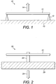
- FIG. 1 shows an explanatory diagram of an ideal simply supported distributed mode actuator (piezoelectric actuator) 10; this is also referred to as a transducer.
- a piezoelectric resonant element 11 is held in ideal simply supported mounts 12.
- the mounts 12 inhibit any translational movement of element 11 in any direction, while allowing for rotational movement about a point of rotation at the end of the beam. This constitutes an ideal simple support.
- the transducer is shown mounted to a mechanical ground 13, and is coupling power or force or velocity 14 into a load which is not shown.
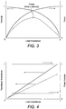
- FIG. 2 shows an explanatory diagram of an inertial piezoelectric actuator 20; also referred to as a transducer.
- a piezoelectric resonant element 21 is mounted on a coupler 22.
- the coupler 22 is itself mounted to the load to be driven 23.
- the coupler 22 couples a power or force or velocity 24 into the load 23.
- a piezoelectric transducer and a coupling means have previously been described in US patent application with publication number US 2007/0025574 A1 .
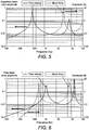
- Figure 3 shows a representation of the velocity and force of a representative transducer as shown in either figure 1 or figure 2 as a function of load impedance, with the resultant power also shown.
- a load impedance varies from zero to a maximum (which is infinite), but is here indicated as 1.
- the velocity of the resonant element of the representative transducer is shown. This has a maximum at zero load impedance and is termed the free velocity. The velocity has a minimum at maximum or infinite load impedance.
- the force that is provided to the load by the resonant element of the transducer is also shown. This has a minimum at zero load impedance and rises to a maximum at the maximum or infinite load impedance.
- the power that is available to be coupled from the transducer to the load is shown, where power is the product of force x velocity.
- the desired force, velocity and power is required to be coupled from the transducer to the load impedance over the frequency range of operation of the transducer, which may extend from 50,000Hz down to effectively 0Hz, which covers but is not limited to an audio frequency range.
- the power that can be coupled from the transducer to the load impedance can be thought of as a figure of merit for the transducer, and the problems associated with coupling a transducer to a load may be easily understood when considering the power.
- transducer applications it is desired to couple a maximum velocity to a load, whereas in some transducer applications it is desired to couple a maximum force to a load. In either or both of these situations it may be desired to couple a maximum possible power to the load available for a particular transducer design thereby minimising the required size of transducer for a particular application.
- the mechanical impedance of the transducer should be matched to that of the load over the frequency range of interest, which would also result in a relatively smooth variation in power, force and velocity with frequency.
- FIG 4 a representation of impedance matching between a load and a transducer is shown, with the resultant power coupled from the transducer to the load also shown.
- the load and transducer impedances are matched, as represented by the inclined solid line, leading to a maximum power transfer as a function of the available power represented by the horizontal solid line at a power transfer level arbitrarily shown as 1.
- the maximum amount of available power may be transferred from the transducer to the load.
- the transducer and load impedances are not matched, for example the transducer impedance is greater than or smaller than the load impedance, then the power transfer can be significantly reduced, for example by an order of magnitude.
- Transducer and load impedances are frequently not matched over the frequency range of operation leading to reduced power transfer, velocities or forces, and to variations of power, force or velocity that are do not smoothly vary with frequency.
- the present invention was made in an attempt to solve these problems.
- transducer that can be used to couple a desired power to a load.
- An inertial transducer is a transducer that is not grounded to a frame or other support and is free to vibrate over an extended region such as the region outside its mounting.
- the resonant element is free to bend and so generate a force via the inertia associated with accelerating and decelerating its own mass during vibration.
- Inertial transducers may be symmetrical or asymmetrical where symmetrical transducers may be formed by a piezoelectric element supported symmetrically on a central coupler or support and asymmetrical transducers may for example be supported in a cantilever type arrangement.
- a resonant element of a piezoelectric element of a transducer may have three distinguishable boundary conditions, namely free, clamped (or fixed) and simply supported (or pinned). For the simply supported case, displacement in any axis is prevented but rotation is allowed.
- a simple support is thus understood as a technical term in acoustical engineering to define the boundary condition of a resonant plate or beam.
- the plate of the transducer is supported to permit pivotal movement about the support but to prevent translational movement relative to the support.
- a simple support is thus distinguished from other boundary conditions where the plate is clamped at its edge or where the plate is free at its edge.
- the benchmark performance for a simply supported, or supported beam, transducer is shown in figure 5 .
- the frequency range of operation is shown varying from 100Hz to 10,000Hz.
- the free velocity (with zero load impedance) is shown on the left vertical axis as a function of frequency, and the block force (with an infinite load impedance) is shown on the right vertical axis as a function of frequency.
- the free velocity exhibits peaks at approximately 500Hz and 4500Hz, with the block force exhibiting a peak at approximately 3000Hz.
- the modal and distributed modal behaviour is shown.
- the benchmark performance for an inertial, or free beam, transducer is shown in figure 6 .
- the frequency range of operation is shown varying from 100Hz to 10,000Hz.
- the free velocity and the block force are again shown as a function of frequency.
- the modal and distributed modal behaviour is shown.
- the inertial transducer has a fall off in frequency at low frequencies.
- the inertial transducer in comparison to the simply supported transducer, exhibits reduced free velocity and block force at low frequencies, but an increased free velocity and block force at higher frequencies.
- Figures 5 and 6 represent the benchmark performance for simply supported and inertial transducers, however in operation transducers are used to drive finite load impedances, rather than zero or infinite impedances.
- Transducers driving finite impedances are shown in figure 7 , where an unmodified inertial transducer and unmodified simply supported transducer are driving a load impedance of 5Ns/m, and where the velocity of a resonant element of the transducer is shown as a function of frequency. This clearly shows that the simply supported transducer has enhanced output over that for the inertial transducer at low frequencies, with the converse applying at high frequencies.
- the piezoelectric element for both the unmodified simply supported and unmodified inertial transducer is a bimorph resonant element, meaning that the piezoelectric resonant element is formed from 2 layers of piezoelectric material and can bend in opposite directions.
- Figure 8 shows a representation of a modified simply supported piezoelectric actuator or transducer 80 according to an aspect of the invention.
- An unmodified simply supported piezoelectric actuator 60 has been modified through the use of impedance matching means 81.
- the use of impedance matching means 81 could be the application of an additional component or components to the simply supported piezoelectric actuator 60.
- the use of impedance matching means 81 could be the substitution of a component part or parts of the simply supported piezoelectric actuator 60 with other component parts.
- Figure 9 shows a representation of a modified inertial piezoelectric actuator or transducer 90 according to an aspect of the invention.
- An unmodified inertial piezoelectric actuator 70 has been modified through the use of impedance matching means 91.
- the use of impedance matching means 91 could be the application of an additional component or components to the inertial piezoelectric actuator 70.
- the use of impedance matching means 91 could be the substitution of a component part or parts of the inertial piezoelectric actuator 70 with other component parts.
- the transducer and load impedances may exhibit a mismatch over the frequency range of interest leading to a reduced power transfer, velocity or force characteristic of the transducer. This is because the impedance of the transducer over the frequency range of interest could be different to, and is likely to be different to, the impedance of the load over the frequency range of interest.
- the load to be driven could have a set impedance or an impedance over a fixed range, for example if a transducer was coupled to the pinna of a person's ear and was being used to excite acoustic vibrations in the pinna to couple sound to the ear in a headphone embodiment.
- the transducer may need to exhibit certain characteristics which leads to the transducer having a certain impedance or range of impedances over the frequency range of operation.
- an impedance matching means does not mean that the impedance of the transducer and the impedance of the load are made to be equal over the frequency range of operation or indeed equal over any frequency over the frequency range of operation.
- Impedance matching refers to a modification of the impedance of the transducer in order that the operation of the transducer over the frequency range of operation is improved, through there being less of an impedance mismatch over the frequency range of operation.
- the impedance matching means is a means to modify the impedance of the transducer, in order to improve the coupling of power, force or velocity from the transducer to the load.
- impedance matching means can be thought of as the provision of another degree of freedom within the mechanical impedance space comprising the mechanical impedance of an unmodified transducer and the mechanical of the load, that allows for the designer/engineer of a transducer to drive a load to design a more optimum or optimum transducer to load driving system.
- the impedance matching means comprises an overmould, for example in the form of a layer, arranged to surround at least part of the piezoelectric device of a transducer.
- the impedance matching means comprises a soft elastomer that covers at least part of the piezoelectric device.
- the soft elastomer may be characterised by a Shore A hardness up to 30.
- the impedance matching means comprises a hard elastomer that covers at least part of the piezoelectric device.
- the hard elastomer may be characterised by a Shore A hardness up to 90.
- the impedance matching means comprises a hard polymer that covers at least part of the piezoelectric device.
- the hard polymer may be characterised by a Shore A hardness up to 100, however typically Shore A hardness applies up to a maximum of 90 and therefore the hard polymer may be characterised by an equivalent Shore D hardness up to 100.
- the applicant has conducted research that has established that care is needed in the application of the impedance matching overmould, because operation of the transducer can be detrimentally affected.
- Incorrect modification means that the overmould layer has been incorrectly applied, and in the cases shown for the simply supported piezoelectric actuator and inertial piezoelectric actuator are representative of an overmould layer that may be applied if the actuators were to be simply made more robust, for example more able to withstand vibrations or being dropped, without optimising the overmould for impedance matching purposes.
- the applicant's research has established that the parameters of the overmould layer arranged to surround at least part of the piezoelectric device need to be selected to provide the required impedance matching between the transducer and the load to provide the desired power, velocity and/or force coupling between or from the transducer to the load.
- the parameters of the overmould to be selected include: the material, which can be a soft or hard elastomer, a rubber material, a polymer material or any other suitable material; the hardness, stiffness, Young's or shear modulus or other material characteristics of the material forming the overmould layer; the thickness of the overmould, especially if the overmould is in the form of a layer, which could vary in thickness at different positions around the piezoelectric layer; and the form of the overmould.
- the form of the overmould layer refers to: a soft elastomer that surrounds the, or part of the, piezoelectric device: a hard elastomer that surrounds the, or part of the, piezoelectric device and that may provide the simple support means or inertial support means or coupling means between the piezoelectric device and the load, a soft or hard polymer that surrounds the, or part of the, piezoelectric device and that may provide the simple support means or inertial support means or coupling means between the piezoelectric device and the load.
- the impedance matching means is referred to as an "overmould" because it is particularly convenient for it to be formed by moulding, e.g. injection moulding.
- moulding e.g. injection moulding.
- suitable design parameters are not limited to moulded impedance matching means and this disclosure is not to be interpreted as limited to moulded impedance matching means.
- an overmould e.g. overmould layer
- an optimised design that comprises a different piezoelectric resonator, different mounting configuration or other different physical aspects to a transducer without an overmould impedance matching means.
- the overmould impedance matching means in addition to providing impedance matching can provide support or resilience to a piezoelectric element or resonator, meaning that the optimised transducer design with an overmould may not be operable if the overmould was removed and the piezoelectric resonator design did not change.
- Use of an overmould may allow for the use of an optimised design of piezoelectric resonator that would be fragile, or otherwise not be able to operate or be liable to failure if the overmould was removed.
- FIG 12 an example of an optimised simply supported piezoelectric actuator 140 according to an aspect of the present invention is shown in cross section, with overmould impedance matching means.
- a generally rectangular piezoelectric bimorph 141 in the form of a beam is provided with impedance matching means in the form of a layer of soft elastomer 143 on each of its major surfaces.
- the elastomer may have a Shore hardness of A30.
- a suitable thickness for the soft elastomer 143 is 0.5mm.
- the piezoelectric bimorph 141 is provided with additional impedance matching means in the form of elastomeric supports 142. Each of the supports may comprise a hard elastomer for example of Shore hardness A70.
- Two supports are provided, positioned at either end of the piezoelectric bimorph or resonant element 141, forming the simple supports or feet for the piezoelectric actuator.
- the layers of elastomer 143 extend over the entire surfaces of the bimorph up to the supports 142.
- the simply supported piezoelectric actuator 140 is mounted to a mechanical ground 13 through the hard elastomer supports or feet 142, which may have a thickness of 1mm.
- the end or periphery of the piezoelectric element 141 terminates within the hard elastomer feet 142.
- the feet 142 may be configured to grip a part of the periphery of the piezoelectric element 141.
- the feet may extend along the full width of the element 141.
- Power 144 is coupled through the soft elastomer layer to a load, not shown but which could for example be the pinna of an ear or a panel of a loudspeaker.
- the layer of soft elastomer 143 and the hard elastomer feet 142 together form an overmould impedance matching means.
- FIG 13 an example of an optimised inertial piezoelectric actuator 150 according to an aspect of the present invention is shown, with alternative overmould impedance matching means.
- a generally planar piezoelectric bimorph 151 in the form of a beam is surrounded by an overmould impedance matching means in the form of a layer of soft elastomer 153 completely enveloping the bimorph 151.
- a suitable Shore hardness for the elastomer is A20.
- a suitable thickness of the soft elastomer 153 is 0.5mm.
- the piezoelectric bimorph 151 is also provided with impedance matching means positioned at the centre of the piezoelectric bimorph or resonant element 151, forming a coupler 152 from the transducer to the load 23 for the piezoelectric actuator.
- the coupler 152 may be in the form of a hard polymer coupler 152 of which a suitable Shore hardness is A or D100.
- the coupler 152 may be shaped to surround a central portion of the bimorph 151.
- the inertial piezoelectric actuator 150 is mounted to the load to be driven 23 through the coupler 152.
- the soft elastomer of the layer 153 is formed into feet 155 extending between the piezoelectric bimorph 151 and the load 23.
- two feet are provided, one at each end of the bimorph, for example positioned 1/3 rd of the way from the end of the piezoelectric bimorph 151.
- the feet 155 act as 'catchers' and act to support the piezoelectric resonator with the soft elastomer layer 153.
- the feet 155 are designed to have a geometry that exhibits flexibility due to the design, allowing the piezoelectric element 151 to vibrate without being restrained or unnecessarily restrained. This allows the optimised design to operate, as discussed above.
- the position 1/3 rd from the end of the piezoelectric element is an optimum position for feet 155 as would be appreciated by the person skilled in the art from an analysis of the angular momentum of the system.
- Power 154 is coupled through the hard polymer coupler 152 to a load 23, which could for example be a panel of a loudspeaker.
- the piezoelectric elements are generally rectangular but they are not limited to such shapes.
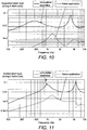
- FIG 14 the velocity as a function of frequency of the optimised simply supported piezoelectric actuator of figure 12 with an overmould layer is shown alongside the unmodified piezoelectric actuator velocity characteristic as shown in figure 7 .
- the performance of the optimised piezoelectric actuator is significantly better than the non-optimised piezoelectric actuator as shown in figure 10 , and is tending toward that of the unmodified piezoelectric actuator.
- the velocity characteristic is shown, and is tending toward that for the unmodified and at some frequencies has improved upon that of the unmodified, however as discussed above the parameters of the impedance matching means have been selected to provide the required impedance matching between the transducer and the load and accordingly the coupling of power from the transducer to the load will now tend toward that desired or required.
- FIG 15 the velocity as a function of frequency of the optimised inertial piezoelectric actuator of figure 13 with an overmould layer is shown alongside the unmodified piezoelectric actuator velocity characteristic as shown in figure 7 .
- the performance of the optimised piezoelectric actuator is significantly better than the non-optimised piezoelectric actuator as shown in figure 11 , and is tending toward that of the unmodified piezoelectric actuator and indeed improves upon the unmodified at certain frequencies.
- the velocity characteristic is shown, and is tending toward that for the unmodified piezoelectric actuator and indeed at certain frequencies has improved upon that of the unmodified, however as discussed above the parameters of the impedance matching means have been selected to provide the required impedance matching between the transducer and the load and accordingly the coupling of power from the transducer to the load will tend toward that desired or required.
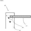
- FIG 16 a schematic diagram of an example of an end mounting for a simply supported piezoelectric actuator 180 according to an aspect of the invention is shown, which shows one end of the simple support of the piezoelectric actuator as shown in figure 12 .
- the simple support means comprises the hard elastomer foot 142, within which is mounted the end or periphery of the piezoelectric resonant element 141.
- a suitable Shore hardness for the foot 142 is 70.
- a translational stiffness k and a rotational stiffness kr for the element 141 are indicated.
- the ideal situations for the end of the piezoelectric element 141 to be constrained from translating i.e., the piezoelectric element 141 as shown in figure 16 should be constrained from moving in the direction of the extent of the foot as shown.
- the piezoelectric beam should be free to rotate about a point situated at the end or periphery of the beam or element 141.
- the end of the piezoelectric element 141 is able to translate, and is not able to rotate as freely as for an ideal simple support configuration, and a result of this is that the position about the which the piezoelectric element 141 rotates is moved inboard from the end of element, where the rotation position is shown in figure 16 as position 183.
- the finite length of the "foot" that is the finite length of the end part or periphery of the piezoelectric resonant element 141 within the hard elastomer foot 142, effectively shifts the rotation point from the end of the beam to the mid-point of foot. This is a parameter that can be varied for improved impedance matching.
- k and kr are inextricably linked, and therefore it is not possible to achieve the ideal simple supported mounting configuration.
- the end mounting configuration shown in figure 1 for the ideal simply supported case where simple support mounts 12 are provided to give the ideal simple support, or end mounting means providing one example of an optimised simple support case as shown in figures 12 and 16 can be considered to form a boundary condition for the periphery or end of the piezoelectric device.
- the parameters of the mounting means can then be selected to provide a required boundary condition for the periphery(s) or end(s) of the piezoelectric device whereby the desired power, force or velocity coupling between the transducer and load is provided.
- the parameters of the mounting means to be selected include: the material, which can be a soft or hard elastomer, a rubber material, a polymer material or any other suitable material; the hardness, stiffness, Young's or shear modulus or other material characteristics of the material forming the mounting means; the thickness and geometry of the mounting means, and any means for artificially constraining the material forming the mounting means to effectively alter its material characteristics.
- the material which can be a soft or hard elastomer, a rubber material, a polymer material or any other suitable material
- the hardness, stiffness, Young's or shear modulus or other material characteristics of the material forming the mounting means the thickness and geometry of the mounting means, and any means for artificially constraining the material forming the mounting means to effectively alter its material characteristics.
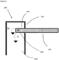
- FIG 17 a further aspect of the invention is shown in figure 17 , showing an example of an end termination of a simply supported piezoelectric actuator, forming a simple support boundary condition.
- the piezoelectric element 141 is mounted so as to partially extend into a hard elastomer foot 192.
- the hard elastomer foot 192 is provided with restraining or constricting means 191.
- the restraining means 191 forms a mechanical restraint around the outer periphery of the foot 192, and inhibits the foot 192 from changing its volume.
- the restraining means is formed from a non-compliant layer, or applique, that surrounds substantially all of the free surface of the foot 192.
- the non-compliant restraining means 191 is formed from a hard polymer or other appropriate material.
- the elasticity of the restraining means or casing is lower than that of the foot 192 or other mount.
- the hard elastomer foot 192 (which may be made of rubber) on the sides, and or top, - the material is being inhibited from changing its volume; the high K values shown in the figure create a high value for k.
- the non-volume-changing rocking motion of the end of the piezoelectric beam 141 activates the low shear modulus values, creating a low value for rotational stiffness kr. This means that by boxing in the hard elastomer foot 192, the shore hardness of the foot can be reduced from that for an unrestrained foot.
- the hard elastomer foot now has a Shore A hardness of 40 as opposed to a Shore A hardness of 70 for an unrestrained foot. This has moved the position around which the end of the piezoelectric element 141 rotates from position 183 to position 193, which means that the rotation position has moved toward the end of the piezoelectric element.
- the simple support boundary condition has become more like an ideal simple support arrangement.
- FIG 18 The result of restraining the hard elastomer foot as shown in figure 17 is shown in figure 18 where the velocity as a function of frequency for the simply supported piezoelectric actuator with an optimised modified unrestrained hard elastomer foot, for the simply supported piezoelectric actuator with an optimised restrained elastomer foot, and for the unmodified simply supported piezoelectric actuator is shown.
- the material of the hard elastomer foot from Shore hardness A70 to 40, and boxing-in the sides, an improvement of between 0.1 and 0.9 dB in the response level is obtained in this example, where the improvement may be greater or less than this.
- the boxing-in or constraining of the mount or foot may be around the sides only but preferably also covers the top as shown.
- the parameters of the mounting means are selected to provide a required boundary condition that allows the operation of the simply supported transducer to operate in a simply supported mode at low frequencies and effectively in an inertial mode at high frequencies.
- figure 19 which shows the velocity as a function of frequency for the simply supported piezoelectric actuator with an optimised modified restrained hard elastomer foot, for the unmodified simply supported piezoelectric actuator and for the unmodified inertial piezoelectric actuator.
- the simply supported piezoelectric actuator with an optimised modified restrained foot operates as in a simply supported mode at low frequencies, and as shown in this example at frequencies above 2-3000Hz, it begins to operate in an inertial mode.
- the hard elastomer feet 142 as shown in figure 16 may have a Shore A hardness of 70, but this could be up to 90.
- the Shear modulus for the hard elastomer may be 2.05MPa.
- the piezoelectric bimorph may incorporate a metallic central vane, extended out from the resonant elements, and the hard elastomer feet can be moulded around the vane. Care must however be taken to ensure that the rotation of the end of the piezoelectric element is not constrained. This means that the properties/parameters of the mounting means can be selected to provide the required boundary conditions, to provide the required or desired coupling of power from the transducer to the load.
- the central vane may be formed from a material other than metal in some examples.
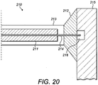
- FIG 20 shows the end termination of a simply supported piezoelectric actuator with an extended vane with a hard elastomer around the central vane, and with a soft elastomer overmould over the piezoelectric element.
- the end termination 210 of one end of a simply supported piezoelectric actuator is shown.
- Piezoelectric bimorph 211 has a central vane 214 extending out from the piezoelectric materials bonded or attached to either side of the vane.
- the vane 214 extends all the way through a hard elastomer foot 212, of an appropriate Shore A hardness that may be up to 90.
- the hard elastomer foot is mounted to a support mount 215, which could be mounted to a mechanical ground.
- the support mount 215 has free space 216 or recess within the part attached to the hard elastomer foot into which the vane 214 extends.
- the space 216 will modify the characteristics of the hard elastomer foot, and forms one of the parameters that need to be considered when selecting the required parameters for the mounting means as discussed above.
- the piezoelectric element is also shown with a soft elastomer overmould layer 213.
- the frequency range of operation may extend below 100Hz, tending towards 0Hz, and may extend above 10,000Hz to 20,000Hz, 30,000Hz, 50,000Hz and above.
- the piezoelectric resonant element may be a unimorph, or a bimorph with a central vane.
- a transducer may be coupled to the panel that forms part of a loudspeaker.
- acoustic vibrations includes vibrations such as pistonic mode vibrations, bending wave vibrations, resonant bending wave vibrations, and other sound or acoustic vibrations known in the art.
- the impedance matching means may lead to a reduction in performance at some frequencies over the frequency range of operation.
- the impedance matching means is applied to the transducer to modify the impedance of the transducer, it is clear that the transducer/load system considered as a whole has had its impedance modified and accordingly, the present invention is considered to cover the modification of the impedance of this whole system.
- the overmould layer covers substantially all of the piezoelectric device.
- the overmould layer covers all of the piezoelectric device.
- the overmould layer covers substantially all of the upper and/or lower surfaces of the resonant element or elements of piezoelectric device.
- the overmould layer covers all of the upper and lower surfaces of the resonant element of piezoelectric device.
- the overmould layer has the added advantage over and above that of providing a required impedance matching between the mechanical impedance of the transducer and the mechanical impedance of the load to provide the required or desired power coupling or force coupling or velocity coupling from the transducer to the load.
- the layer of soft elastomer 143 alone forms the overmould layer to provide the impedance matching means.
- the hard elastomer feet 142 alone form the overmould layer to provide the impedance matching means.
- the hard elastomer feet 142 have a different shore A hardness.
- a stub or coupler may be mounted to the piezoelectric resonant element 141, on the side of the piezoelectric element 141 opposite to the mechanical ground.
- This stub or coupler may be used to couple to the load to be driven, such as a panel of a loudspeaker.
- the stub or coupler may be used to couple to a second piezoelectric element positioned substantially parallel to piezoelectric element 141 in a stacked piezoelectric transducer.
- the hard elastomer feet 142 could be coupled to the load to be driven rather than to a mechanical ground.
- velocity or force may be coupled to the load, or velocity and force may be coupled to the load, or power, velocity and force may be coupled to the load.
- the thickness of the soft elastomer 143 is less than or greater than 0.5mm, and in other examples the soft elastomer 143 has a Shore A hardness less than or greater than 30.
- the thickness of the soft elastomer 143 varies across the piezoelectric bimorph 141.
- the thickness may be less at the centre of the resonator 141 than at the ends, or the thickness may be greater at the centre than the ends.
- the soft elastomer 143 is only applied to one side of the piezoelectric bimorph 141.
- the hard elastomer feet 142 have a shore A hardness less than or greater than 70, and may have a thickness less than or greater than 1mm.
- the piezoelectric element 141 extends one quarter of the way through the hard elastomer feet 142, or may extend one half of the way through or three quarters of the way through the hard elastomer feet 142. Other terminating positions are possible.
- the piezoelectric element 141 extends all of the way through the hard elastomer feet 142, and the end of the piezoelectric element may be coincident with the outer extent of the hard elastomer feet 142.
- the piezoelectric bimorph 141 may extend all the way through the hard elastomer feet, and extend 1mm, 2mm or 4mm out of the other side of a hard elastomer foot 142. Other extension distances are possible.
- the layer of soft elastomer 153 alone forms the overmould layer to provide the impedance matching means.
- the soft elastomer feet 155 alone form the overmould layer to provide the impedance matching means.
- the hard polymer coupler 152 alone forms the overmould layer to provide the impedance matching means.
- the coupler 152 may be used to couple to a second piezoelectric element positioned substantially parallel to piezoelectric element 151 in a stacked piezoelectric transducer. In this way there may be more than one additional resonator element making up the piezoelectric actuator transducer, with the overmould layer arranged to surround all or some of this piezoelectric device.
- the coupler 152 may have a shore A or D hardness less than 100.
- velocity or force may be coupled to the load, or velocity and force may be coupled to the load, or power, velocity and force may be coupled to the load.
- the thickness of the soft elastomer 153 may be less than or greater than 0.5mm, and in other examples the soft elastomer 153 has a Shore A hardness less than or greater than 20.
- the thickness of the soft elastomer 153 varies across the piezoelectric bimorph 151.
- the thickness may be less at the centre of the resonator 151 than at the ends, or the thickness may be greater at the centre than the ends.
- the soft elastomer 153 is only applied to one side of the piezoelectric bimorph 151.
- the soft elastomer feet 155 may be at a position other than 1/3 rd the way from the end of the piezoelectric bimorph 151, such as at the mid point or any other suitable position.
- the soft elastomer feet 155 may be of a different geometry to that as shown in figure 13 if they continue to function as 'catcher', as would be appreciated by the person skilled in the art.
- optimised simply supported piezoelectric actuator as shown in figure 13 , there may be more than one the soft elastomer foot 155 along either side of the piezoelectric element 151.
- the piezoelectric element 151 may only have one part extending laterally from the support 152. This means for example that the piezoelectric beam on the right hand side of the coupler 152 may be omitted, the transducer then not being symmetrical.
- optimised simply supported piezoelectric actuator as shown in figure 13 may be symmetrical or asymmetrical (a cantilever type arrangement).
- a cantilever type arrangement the symmetrical example shown in figure 13 may be essentially cut in half - with a piezoelectric element only extending to one side of the support.
- the frequency responses may look the same, or similar, to that shown for the symmetrical example shown in figure 13 , except that there may be only half the blocked-force generated as would be anticipated for symmetrical arrangement.
- the soft elastomer feet 155 may be omitted.
- the simple support could be used to mount a touchscreen panel, and/or loudspeaker panel.
- Such a simple support as described above could be used to mount around the edge or periphery of the touchscreen or loudspeaker panel.
Landscapes
- Engineering & Computer Science (AREA)
- Physics & Mathematics (AREA)
- Acoustics & Sound (AREA)
- Multimedia (AREA)
- Mechanical Engineering (AREA)
- Signal Processing (AREA)
- Piezo-Electric Transducers For Audible Bands (AREA)
- Transducers For Ultrasonic Waves (AREA)
Applications Claiming Priority (2)
| Application Number | Priority Date | Filing Date | Title |
|---|---|---|---|
| GBGB1207045.4A GB201207045D0 (en) | 2012-04-23 | 2012-04-23 | Transducers with improved impedance matching |
| PCT/GB2013/051028 WO2013160669A1 (en) | 2012-04-23 | 2013-04-23 | Transducers with improved impedance matching |
Publications (2)
| Publication Number | Publication Date |
|---|---|
| EP2841213A1 EP2841213A1 (en) | 2015-03-04 |
| EP2841213B1 true EP2841213B1 (en) | 2017-02-01 |
Family
ID=46261683
Family Applications (1)
| Application Number | Title | Priority Date | Filing Date |
|---|---|---|---|
| EP13723904.2A Active EP2841213B1 (en) | 2012-04-23 | 2013-04-23 | Transducers with improved impedance matching |
Country Status (7)
| Country | Link |
|---|---|
| US (3) | US20150243874A1 (ko) |
| EP (1) | EP2841213B1 (ko) |
| JP (1) | JP6293733B2 (ko) |
| KR (1) | KR102068270B1 (ko) |
| CN (1) | CN104602827B (ko) |
| GB (1) | GB201207045D0 (ko) |
| WO (1) | WO2013160669A1 (ko) |
Families Citing this family (10)
| Publication number | Priority date | Publication date | Assignee | Title |
|---|---|---|---|---|
| GB201207045D0 (en) * | 2012-04-23 | 2012-06-06 | Hiwave Technologies Uk Ltd | Transducers with improved impedance matching |
| JP6524467B2 (ja) * | 2015-11-06 | 2019-06-05 | 日本特殊陶業株式会社 | 圧電アクチュエータおよびその製造方法 |
| US10356523B2 (en) * | 2017-12-13 | 2019-07-16 | Nvf Tech Ltd | Distributed mode loudspeaker actuator including patterned electrodes |
| US10476461B2 (en) | 2017-12-20 | 2019-11-12 | Nvf Tech Ltd | Active distributed mode actuator |
| US10477321B2 (en) | 2018-03-05 | 2019-11-12 | Google Llc | Driving distributed mode loudspeaker actuator that includes patterned electrodes |
| US10631072B2 (en) * | 2018-06-25 | 2020-04-21 | Google Llc | Actuator for distributed mode loudspeaker with extended damper and systems including the same |
| US10462574B1 (en) | 2018-11-30 | 2019-10-29 | Google Llc | Reinforced actuators for distributed mode loudspeakers |
| US10848875B2 (en) * | 2018-11-30 | 2020-11-24 | Google Llc | Reinforced actuators for distributed mode loudspeakers |
| CN113808560A (zh) * | 2020-06-12 | 2021-12-17 | 香港科技大学 | 基于阻抗匹配的复合超材料的超薄宽频水下吸声器 |
| DE102020121337A1 (de) * | 2020-08-13 | 2022-02-17 | Tdk Electronics Ag | Piezoelektrischer Wandler und Verfahren zur Einstellung der elektromechanischen Eigenschaften eines piezoelektrischen Wandlers |
Family Cites Families (18)
| Publication number | Priority date | Publication date | Assignee | Title |
|---|---|---|---|---|
| US2326923A (en) * | 1941-09-30 | 1943-08-17 | Rca Corp | Art of mounting piezoelectric crystals |
| US4736129A (en) * | 1985-05-30 | 1988-04-05 | Marcon Electronics Co., Ltd. | Ultrasonic motor |
| US4642511A (en) * | 1986-03-31 | 1987-02-10 | Motorola, Inc. | Edge-mounting configuration for at-strip resonators |
| JPH11164396A (ja) * | 1997-09-25 | 1999-06-18 | Matsushita Electric Ind Co Ltd | 圧電スピーカおよびその製造方法 |
| US6307302B1 (en) * | 1999-07-23 | 2001-10-23 | Measurement Specialities, Inc. | Ultrasonic transducer having impedance matching layer |
| US6262517B1 (en) * | 2000-02-11 | 2001-07-17 | Materials Systems, Inc. | Pressure resistant piezoelectric acoustic sensor |
| EP1396172A2 (en) * | 2001-01-05 | 2004-03-10 | ANGELSEN, Bjorn A. J. | Wideband transducer |
| GB0321617D0 (en) * | 2003-09-10 | 2003-10-15 | New Transducers Ltd | Audio apparatus |
| JP2006352464A (ja) * | 2005-06-15 | 2006-12-28 | Nec Tokin Corp | 音響振動発生素子 |
| JP2008061081A (ja) * | 2006-09-01 | 2008-03-13 | Kenwood Corp | 圧電スピーカ |
| GB0710378D0 (en) * | 2007-05-31 | 2007-07-11 | New Transducers Ltd | Audio apparatus |
| JP2010027500A (ja) * | 2008-07-23 | 2010-02-04 | Tdk Corp | 有機el表示装置及びその製造方法 |
| US8006917B2 (en) * | 2008-08-26 | 2011-08-30 | General Electric Company | Method and apparatus for reducing acoustic noise in a synthetic jet |
| WO2010074206A1 (ja) * | 2008-12-26 | 2010-07-01 | パナソニック電工株式会社 | 圧電スピーカ、これを用いた圧電音響装置および警報機付きセンサ |
| JP5604096B2 (ja) * | 2009-12-25 | 2014-10-08 | 東京計器株式会社 | 液圧システムの圧力保持機構 |
| GB201207045D0 (en) * | 2012-04-23 | 2012-06-06 | Hiwave Technologies Uk Ltd | Transducers with improved impedance matching |
| KR102125405B1 (ko) * | 2018-08-29 | 2020-06-22 | 한국과학기술연구원 | 넓은 동작 주파수 범위를 갖는 자가 공진 조절 압전 에너지 하베스터 |
| US11482659B2 (en) * | 2018-09-26 | 2022-10-25 | Apple Inc. | Composite piezoelectric actuator |
-
2012
- 2012-04-23 GB GBGB1207045.4A patent/GB201207045D0/en not_active Ceased
-
2013
- 2013-04-23 EP EP13723904.2A patent/EP2841213B1/en active Active
- 2013-04-23 KR KR1020147032763A patent/KR102068270B1/ko active IP Right Grant
- 2013-04-23 US US14/396,318 patent/US20150243874A1/en not_active Abandoned
- 2013-04-23 CN CN201380032985.XA patent/CN104602827B/zh active Active
- 2013-04-23 WO PCT/GB2013/051028 patent/WO2013160669A1/en active Application Filing
- 2013-04-23 JP JP2015507593A patent/JP6293733B2/ja active Active
-
2017
- 2017-11-08 US US15/806,823 patent/US10714673B2/en active Active
-
2020
- 2020-06-15 US US16/901,293 patent/US11730061B2/en active Active
Also Published As
| Publication number | Publication date |
|---|---|
| CN104602827B (zh) | 2017-10-03 |
| EP2841213A1 (en) | 2015-03-04 |
| WO2013160669A1 (en) | 2013-10-31 |
| JP6293733B2 (ja) | 2018-03-14 |
| US10714673B2 (en) | 2020-07-14 |
| JP2015520963A (ja) | 2015-07-23 |
| US20180102471A1 (en) | 2018-04-12 |
| US20150243874A1 (en) | 2015-08-27 |
| CN104602827A (zh) | 2015-05-06 |
| KR102068270B1 (ko) | 2020-01-20 |
| KR20150048666A (ko) | 2015-05-07 |
| US20200321511A1 (en) | 2020-10-08 |
| GB201207045D0 (en) | 2012-06-06 |
| US11730061B2 (en) | 2023-08-15 |
Similar Documents
| Publication | Publication Date | Title |
|---|---|---|
| EP2841213B1 (en) | Transducers with improved impedance matching | |
| EP1762119B1 (en) | Piezoelectric inertial transducer | |
| US9094743B2 (en) | Acoustic transducers | |
| US7369115B2 (en) | Haptic devices having multiple operational modes including at least one resonant mode | |
| KR101630353B1 (ko) | 질량체를 가진 압전 스피커 및 그 제조 방법 | |
| US7475598B2 (en) | Electromechanical force transducer | |
| US20050168111A1 (en) | Transducer | |
| KR100818482B1 (ko) | 압전 모터 | |
| EP1665879B1 (en) | Electromechanical force transducer | |
| CN111988709A (zh) | 用于表面致动的扁平形换能器 | |
| US20090051248A1 (en) | Longitudinally driven slotted cylinder transducer | |
| JP5261152B2 (ja) | 超音波振動子 | |
| JP2004097851A (ja) | 超音波振動装置 | |
| US20120321824A1 (en) | Transducer module | |
| JP2021027580A (ja) | 圧電スピーカー | |
| WO2006000751A1 (en) | Bending wave devices |
Legal Events
| Date | Code | Title | Description |
|---|---|---|---|
| PUAI | Public reference made under article 153(3) epc to a published international application that has entered the european phase |
Free format text: ORIGINAL CODE: 0009012 |
|
| 17P | Request for examination filed |
Effective date: 20141119 |
|
| AK | Designated contracting states |
Kind code of ref document: A1 Designated state(s): AL AT BE BG CH CY CZ DE DK EE ES FI FR GB GR HR HU IE IS IT LI LT LU LV MC MK MT NL NO PL PT RO RS SE SI SK SM TR |
|
| AX | Request for extension of the european patent |
Extension state: BA ME |
|
| DAX | Request for extension of the european patent (deleted) | ||
| 17Q | First examination report despatched |
Effective date: 20151216 |
|
| RIC1 | Information provided on ipc code assigned before grant |
Ipc: G10K 11/00 20060101ALI20160720BHEP Ipc: H04R 17/00 20060101ALI20160720BHEP Ipc: G10K 11/02 20060101ALI20160720BHEP Ipc: B06B 1/06 20060101AFI20160720BHEP Ipc: H01L 41/09 20060101ALN20160720BHEP Ipc: H01L 41/053 20060101ALI20160720BHEP |
|
| GRAP | Despatch of communication of intention to grant a patent |
Free format text: ORIGINAL CODE: EPIDOSNIGR1 |
|
| RIC1 | Information provided on ipc code assigned before grant |
Ipc: B06B 1/06 20060101AFI20160726BHEP Ipc: G10K 11/02 20060101ALI20160726BHEP Ipc: G10K 11/00 20060101ALI20160726BHEP Ipc: H01L 41/053 20060101ALI20160726BHEP Ipc: H01L 41/09 20060101ALN20160726BHEP Ipc: H04R 17/00 20060101ALI20160726BHEP |
|
| INTG | Intention to grant announced |
Effective date: 20160826 |
|
| GRAS | Grant fee paid |
Free format text: ORIGINAL CODE: EPIDOSNIGR3 |
|
| GRAA | (expected) grant |
Free format text: ORIGINAL CODE: 0009210 |
|
| AK | Designated contracting states |
Kind code of ref document: B1 Designated state(s): AL AT BE BG CH CY CZ DE DK EE ES FI FR GB GR HR HU IE IS IT LI LT LU LV MC MK MT NL NO PL PT RO RS SE SI SK SM TR |
|
| REG | Reference to a national code |
Ref country code: GB Ref legal event code: FG4D |
|
| REG | Reference to a national code |
Ref country code: CH Ref legal event code: EP Ref country code: AT Ref legal event code: REF Ref document number: 865102 Country of ref document: AT Kind code of ref document: T Effective date: 20170215 |
|
| REG | Reference to a national code |
Ref country code: IE Ref legal event code: FG4D |
|
| REG | Reference to a national code |
Ref country code: DE Ref legal event code: R096 Ref document number: 602013017018 Country of ref document: DE |
|
| REG | Reference to a national code |
Ref country code: NL Ref legal event code: MP Effective date: 20170201 |
|
| REG | Reference to a national code |
Ref country code: LT Ref legal event code: MG4D |
|
| REG | Reference to a national code |
Ref country code: AT Ref legal event code: MK05 Ref document number: 865102 Country of ref document: AT Kind code of ref document: T Effective date: 20170201 |
|
| PG25 | Lapsed in a contracting state [announced via postgrant information from national office to epo] |
Ref country code: GR Free format text: LAPSE BECAUSE OF FAILURE TO SUBMIT A TRANSLATION OF THE DESCRIPTION OR TO PAY THE FEE WITHIN THE PRESCRIBED TIME-LIMIT Effective date: 20170502 Ref country code: IS Free format text: LAPSE BECAUSE OF FAILURE TO SUBMIT A TRANSLATION OF THE DESCRIPTION OR TO PAY THE FEE WITHIN THE PRESCRIBED TIME-LIMIT Effective date: 20170601 Ref country code: NO Free format text: LAPSE BECAUSE OF FAILURE TO SUBMIT A TRANSLATION OF THE DESCRIPTION OR TO PAY THE FEE WITHIN THE PRESCRIBED TIME-LIMIT Effective date: 20170501 Ref country code: HR Free format text: LAPSE BECAUSE OF FAILURE TO SUBMIT A TRANSLATION OF THE DESCRIPTION OR TO PAY THE FEE WITHIN THE PRESCRIBED TIME-LIMIT Effective date: 20170201 Ref country code: LT Free format text: LAPSE BECAUSE OF FAILURE TO SUBMIT A TRANSLATION OF THE DESCRIPTION OR TO PAY THE FEE WITHIN THE PRESCRIBED TIME-LIMIT Effective date: 20170201 Ref country code: FI Free format text: LAPSE BECAUSE OF FAILURE TO SUBMIT A TRANSLATION OF THE DESCRIPTION OR TO PAY THE FEE WITHIN THE PRESCRIBED TIME-LIMIT Effective date: 20170201 |
|
| RAP2 | Party data changed (patent owner data changed or rights of a patent transferred) |
Owner name: NVF TECH LTD |
|
| PG25 | Lapsed in a contracting state [announced via postgrant information from national office to epo] |
Ref country code: BG Free format text: LAPSE BECAUSE OF FAILURE TO SUBMIT A TRANSLATION OF THE DESCRIPTION OR TO PAY THE FEE WITHIN THE PRESCRIBED TIME-LIMIT Effective date: 20170501 Ref country code: RS Free format text: LAPSE BECAUSE OF FAILURE TO SUBMIT A TRANSLATION OF THE DESCRIPTION OR TO PAY THE FEE WITHIN THE PRESCRIBED TIME-LIMIT Effective date: 20170201 Ref country code: PT Free format text: LAPSE BECAUSE OF FAILURE TO SUBMIT A TRANSLATION OF THE DESCRIPTION OR TO PAY THE FEE WITHIN THE PRESCRIBED TIME-LIMIT Effective date: 20170601 Ref country code: PL Free format text: LAPSE BECAUSE OF FAILURE TO SUBMIT A TRANSLATION OF THE DESCRIPTION OR TO PAY THE FEE WITHIN THE PRESCRIBED TIME-LIMIT Effective date: 20170201 Ref country code: LV Free format text: LAPSE BECAUSE OF FAILURE TO SUBMIT A TRANSLATION OF THE DESCRIPTION OR TO PAY THE FEE WITHIN THE PRESCRIBED TIME-LIMIT Effective date: 20170201 Ref country code: ES Free format text: LAPSE BECAUSE OF FAILURE TO SUBMIT A TRANSLATION OF THE DESCRIPTION OR TO PAY THE FEE WITHIN THE PRESCRIBED TIME-LIMIT Effective date: 20170201 Ref country code: NL Free format text: LAPSE BECAUSE OF FAILURE TO SUBMIT A TRANSLATION OF THE DESCRIPTION OR TO PAY THE FEE WITHIN THE PRESCRIBED TIME-LIMIT Effective date: 20170201 Ref country code: AT Free format text: LAPSE BECAUSE OF FAILURE TO SUBMIT A TRANSLATION OF THE DESCRIPTION OR TO PAY THE FEE WITHIN THE PRESCRIBED TIME-LIMIT Effective date: 20170201 Ref country code: SE Free format text: LAPSE BECAUSE OF FAILURE TO SUBMIT A TRANSLATION OF THE DESCRIPTION OR TO PAY THE FEE WITHIN THE PRESCRIBED TIME-LIMIT Effective date: 20170201 |
|
| PG25 | Lapsed in a contracting state [announced via postgrant information from national office to epo] |
Ref country code: CZ Free format text: LAPSE BECAUSE OF FAILURE TO SUBMIT A TRANSLATION OF THE DESCRIPTION OR TO PAY THE FEE WITHIN THE PRESCRIBED TIME-LIMIT Effective date: 20170201 Ref country code: IT Free format text: LAPSE BECAUSE OF FAILURE TO SUBMIT A TRANSLATION OF THE DESCRIPTION OR TO PAY THE FEE WITHIN THE PRESCRIBED TIME-LIMIT Effective date: 20170201 Ref country code: EE Free format text: LAPSE BECAUSE OF FAILURE TO SUBMIT A TRANSLATION OF THE DESCRIPTION OR TO PAY THE FEE WITHIN THE PRESCRIBED TIME-LIMIT Effective date: 20170201 Ref country code: RO Free format text: LAPSE BECAUSE OF FAILURE TO SUBMIT A TRANSLATION OF THE DESCRIPTION OR TO PAY THE FEE WITHIN THE PRESCRIBED TIME-LIMIT Effective date: 20170201 Ref country code: SK Free format text: LAPSE BECAUSE OF FAILURE TO SUBMIT A TRANSLATION OF THE DESCRIPTION OR TO PAY THE FEE WITHIN THE PRESCRIBED TIME-LIMIT Effective date: 20170201 |
|
| REG | Reference to a national code |
Ref country code: DE Ref legal event code: R097 Ref document number: 602013017018 Country of ref document: DE |
|
| PG25 | Lapsed in a contracting state [announced via postgrant information from national office to epo] |
Ref country code: SM Free format text: LAPSE BECAUSE OF FAILURE TO SUBMIT A TRANSLATION OF THE DESCRIPTION OR TO PAY THE FEE WITHIN THE PRESCRIBED TIME-LIMIT Effective date: 20170201 Ref country code: DK Free format text: LAPSE BECAUSE OF FAILURE TO SUBMIT A TRANSLATION OF THE DESCRIPTION OR TO PAY THE FEE WITHIN THE PRESCRIBED TIME-LIMIT Effective date: 20170201 |
|
| REG | Reference to a national code |
Ref country code: CH Ref legal event code: PL |
|
| PLBE | No opposition filed within time limit |
Free format text: ORIGINAL CODE: 0009261 |
|
| STAA | Information on the status of an ep patent application or granted ep patent |
Free format text: STATUS: NO OPPOSITION FILED WITHIN TIME LIMIT |
|
| 26N | No opposition filed |
Effective date: 20171103 |
|
| REG | Reference to a national code |
Ref country code: IE Ref legal event code: MM4A |
|
| REG | Reference to a national code |
Ref country code: FR Ref legal event code: ST Effective date: 20171229 |
|
| PG25 | Lapsed in a contracting state [announced via postgrant information from national office to epo] |
Ref country code: FR Free format text: LAPSE BECAUSE OF NON-PAYMENT OF DUE FEES Effective date: 20170502 Ref country code: MC Free format text: LAPSE BECAUSE OF FAILURE TO SUBMIT A TRANSLATION OF THE DESCRIPTION OR TO PAY THE FEE WITHIN THE PRESCRIBED TIME-LIMIT Effective date: 20170201 |
|
| PG25 | Lapsed in a contracting state [announced via postgrant information from national office to epo] |
Ref country code: CH Free format text: LAPSE BECAUSE OF NON-PAYMENT OF DUE FEES Effective date: 20170430 Ref country code: LI Free format text: LAPSE BECAUSE OF NON-PAYMENT OF DUE FEES Effective date: 20170430 Ref country code: SI Free format text: LAPSE BECAUSE OF FAILURE TO SUBMIT A TRANSLATION OF THE DESCRIPTION OR TO PAY THE FEE WITHIN THE PRESCRIBED TIME-LIMIT Effective date: 20170201 Ref country code: LU Free format text: LAPSE BECAUSE OF NON-PAYMENT OF DUE FEES Effective date: 20170423 |
|
| REG | Reference to a national code |
Ref country code: BE Ref legal event code: MM Effective date: 20170430 |
|
| PG25 | Lapsed in a contracting state [announced via postgrant information from national office to epo] |
Ref country code: IE Free format text: LAPSE BECAUSE OF NON-PAYMENT OF DUE FEES Effective date: 20170423 |
|
| PG25 | Lapsed in a contracting state [announced via postgrant information from national office to epo] |
Ref country code: BE Free format text: LAPSE BECAUSE OF NON-PAYMENT OF DUE FEES Effective date: 20170430 |
|
| PG25 | Lapsed in a contracting state [announced via postgrant information from national office to epo] |
Ref country code: MT Free format text: LAPSE BECAUSE OF NON-PAYMENT OF DUE FEES Effective date: 20170423 |
|
| PG25 | Lapsed in a contracting state [announced via postgrant information from national office to epo] |
Ref country code: HU Free format text: LAPSE BECAUSE OF FAILURE TO SUBMIT A TRANSLATION OF THE DESCRIPTION OR TO PAY THE FEE WITHIN THE PRESCRIBED TIME-LIMIT; INVALID AB INITIO Effective date: 20130423 |
|
| PG25 | Lapsed in a contracting state [announced via postgrant information from national office to epo] |
Ref country code: CY Free format text: LAPSE BECAUSE OF FAILURE TO SUBMIT A TRANSLATION OF THE DESCRIPTION OR TO PAY THE FEE WITHIN THE PRESCRIBED TIME-LIMIT Effective date: 20170201 |
|
| PG25 | Lapsed in a contracting state [announced via postgrant information from national office to epo] |
Ref country code: MK Free format text: LAPSE BECAUSE OF FAILURE TO SUBMIT A TRANSLATION OF THE DESCRIPTION OR TO PAY THE FEE WITHIN THE PRESCRIBED TIME-LIMIT Effective date: 20170201 |
|
| REG | Reference to a national code |
Ref country code: DE Ref legal event code: R082 Ref document number: 602013017018 Country of ref document: DE Representative=s name: MARKS & CLERK (LUXEMBOURG) LLP, LU Ref country code: DE Ref legal event code: R082 Ref document number: 602013017018 Country of ref document: DE Representative=s name: POLVERARI, LUCA, DIPL.-ING., LU |
|
| REG | Reference to a national code |
Ref country code: DE Ref legal event code: R082 Ref document number: 602013017018 Country of ref document: DE Representative=s name: MARKS & CLERK (LUXEMBOURG) LLP, LU Ref country code: DE Ref legal event code: R081 Ref document number: 602013017018 Country of ref document: DE Owner name: NVF TECH LTD., GB Free format text: FORMER OWNER: HIWAVE TECHNOLOGIES (UK) LTD., CAMBRIDGE, GB Ref country code: DE Ref legal event code: R081 Ref document number: 602013017018 Country of ref document: DE Owner name: GOOGLE LLC, MOUNTAIN VIEW, US Free format text: FORMER OWNER: HIWAVE TECHNOLOGIES (UK) LTD., CAMBRIDGE, GB Ref country code: DE Ref legal event code: R082 Ref document number: 602013017018 Country of ref document: DE Representative=s name: POLVERARI, LUCA, DIPL.-ING., LU |
|
| PG25 | Lapsed in a contracting state [announced via postgrant information from national office to epo] |
Ref country code: TR Free format text: LAPSE BECAUSE OF FAILURE TO SUBMIT A TRANSLATION OF THE DESCRIPTION OR TO PAY THE FEE WITHIN THE PRESCRIBED TIME-LIMIT Effective date: 20170201 |
|
| REG | Reference to a national code |
Ref country code: DE Ref legal event code: R082 Ref document number: 602013017018 Country of ref document: DE Representative=s name: POLVERARI, LUCA, DIPL.-ING., LU Ref country code: DE Ref legal event code: R081 Ref document number: 602013017018 Country of ref document: DE Owner name: GOOGLE LLC, MOUNTAIN VIEW, US Free format text: FORMER OWNER: NVF TECH LTD., LONDON, GB |
|
| REG | Reference to a national code |
Ref country code: GB Ref legal event code: 732E Free format text: REGISTERED BETWEEN 20200528 AND 20200603 |
|
| PG25 | Lapsed in a contracting state [announced via postgrant information from national office to epo] |
Ref country code: AL Free format text: LAPSE BECAUSE OF FAILURE TO SUBMIT A TRANSLATION OF THE DESCRIPTION OR TO PAY THE FEE WITHIN THE PRESCRIBED TIME-LIMIT Effective date: 20170201 |
|
| P01 | Opt-out of the competence of the unified patent court (upc) registered |
Effective date: 20230516 |
|
| PGFP | Annual fee paid to national office [announced via postgrant information from national office to epo] |
Ref country code: DE Payment date: 20230427 Year of fee payment: 11 |
|
| PGFP | Annual fee paid to national office [announced via postgrant information from national office to epo] |
Ref country code: GB Payment date: 20230427 Year of fee payment: 11 |