EP2841190B1 - Device for transporting viscous compounds and pastes - Google Patents
Device for transporting viscous compounds and pastes Download PDFInfo
- Publication number
- EP2841190B1 EP2841190B1 EP13723420.9A EP13723420A EP2841190B1 EP 2841190 B1 EP2841190 B1 EP 2841190B1 EP 13723420 A EP13723420 A EP 13723420A EP 2841190 B1 EP2841190 B1 EP 2841190B1
- Authority
- EP
- European Patent Office
- Prior art keywords
- angle
- shaft
- transport
- screw
- bars
- Prior art date
- Legal status (The legal status is an assumption and is not a legal conclusion. Google has not performed a legal analysis and makes no representation as to the accuracy of the status listed.)
- Active
Links
Images


Classifications
-
- B—PERFORMING OPERATIONS; TRANSPORTING
- B01—PHYSICAL OR CHEMICAL PROCESSES OR APPARATUS IN GENERAL
- B01F—MIXING, e.g. DISSOLVING, EMULSIFYING OR DISPERSING
- B01F27/00—Mixers with rotary stirring devices in fixed receptacles; Kneaders
- B01F27/05—Stirrers
- B01F27/07—Stirrers characterised by their mounting on the shaft
- B01F27/072—Stirrers characterised by their mounting on the shaft characterised by the disposition of the stirrers with respect to the rotating axis
- B01F27/0726—Stirrers characterised by their mounting on the shaft characterised by the disposition of the stirrers with respect to the rotating axis having stirring elements connected to the stirrer shaft each by a single radial rod, other than open frameworks
-
- B—PERFORMING OPERATIONS; TRANSPORTING
- B01—PHYSICAL OR CHEMICAL PROCESSES OR APPARATUS IN GENERAL
- B01F—MIXING, e.g. DISSOLVING, EMULSIFYING OR DISPERSING
- B01F27/00—Mixers with rotary stirring devices in fixed receptacles; Kneaders
- B01F27/60—Mixers with rotary stirring devices in fixed receptacles; Kneaders with stirrers rotating about a horizontal or inclined axis
- B01F27/70—Mixers with rotary stirring devices in fixed receptacles; Kneaders with stirrers rotating about a horizontal or inclined axis with paddles, blades or arms
-
- B—PERFORMING OPERATIONS; TRANSPORTING
- B29—WORKING OF PLASTICS; WORKING OF SUBSTANCES IN A PLASTIC STATE IN GENERAL
- B29B—PREPARATION OR PRETREATMENT OF THE MATERIAL TO BE SHAPED; MAKING GRANULES OR PREFORMS; RECOVERY OF PLASTICS OR OTHER CONSTITUENTS OF WASTE MATERIAL CONTAINING PLASTICS
- B29B7/00—Mixing; Kneading
- B29B7/80—Component parts, details or accessories; Auxiliary operations
- B29B7/802—Constructions or methods for cleaning the mixing or kneading device
-
- B—PERFORMING OPERATIONS; TRANSPORTING
- B01—PHYSICAL OR CHEMICAL PROCESSES OR APPARATUS IN GENERAL
- B01F—MIXING, e.g. DISSOLVING, EMULSIFYING OR DISPERSING
- B01F27/00—Mixers with rotary stirring devices in fixed receptacles; Kneaders
-
- B—PERFORMING OPERATIONS; TRANSPORTING
- B01—PHYSICAL OR CHEMICAL PROCESSES OR APPARATUS IN GENERAL
- B01F—MIXING, e.g. DISSOLVING, EMULSIFYING OR DISPERSING
- B01F27/00—Mixers with rotary stirring devices in fixed receptacles; Kneaders
- B01F27/05—Stirrers
- B01F27/09—Stirrers characterised by the mounting of the stirrers with respect to the receptacle
- B01F27/091—Stirrers characterised by the mounting of the stirrers with respect to the receptacle with elements co-operating with receptacle wall or bottom, e.g. for scraping the receptacle wall
-
- B—PERFORMING OPERATIONS; TRANSPORTING
- B01—PHYSICAL OR CHEMICAL PROCESSES OR APPARATUS IN GENERAL
- B01F—MIXING, e.g. DISSOLVING, EMULSIFYING OR DISPERSING
- B01F27/00—Mixers with rotary stirring devices in fixed receptacles; Kneaders
- B01F27/60—Mixers with rotary stirring devices in fixed receptacles; Kneaders with stirrers rotating about a horizontal or inclined axis
- B01F27/70—Mixers with rotary stirring devices in fixed receptacles; Kneaders with stirrers rotating about a horizontal or inclined axis with paddles, blades or arms
- B01F27/701—Mixers with rotary stirring devices in fixed receptacles; Kneaders with stirrers rotating about a horizontal or inclined axis with paddles, blades or arms comprising two or more shafts, e.g. in consecutive mixing chambers
-
- B—PERFORMING OPERATIONS; TRANSPORTING
- B01—PHYSICAL OR CHEMICAL PROCESSES OR APPARATUS IN GENERAL
- B01F—MIXING, e.g. DISSOLVING, EMULSIFYING OR DISPERSING
- B01F27/00—Mixers with rotary stirring devices in fixed receptacles; Kneaders
- B01F27/60—Mixers with rotary stirring devices in fixed receptacles; Kneaders with stirrers rotating about a horizontal or inclined axis
- B01F27/70—Mixers with rotary stirring devices in fixed receptacles; Kneaders with stirrers rotating about a horizontal or inclined axis with paddles, blades or arms
- B01F27/707—Mixers with rotary stirring devices in fixed receptacles; Kneaders with stirrers rotating about a horizontal or inclined axis with paddles, blades or arms the paddles co-operating, e.g. intermeshing, with elements on the receptacle wall
-
- B—PERFORMING OPERATIONS; TRANSPORTING
- B29—WORKING OF PLASTICS; WORKING OF SUBSTANCES IN A PLASTIC STATE IN GENERAL
- B29B—PREPARATION OR PRETREATMENT OF THE MATERIAL TO BE SHAPED; MAKING GRANULES OR PREFORMS; RECOVERY OF PLASTICS OR OTHER CONSTITUENTS OF WASTE MATERIAL CONTAINING PLASTICS
- B29B7/00—Mixing; Kneading
- B29B7/30—Mixing; Kneading continuous, with mechanical mixing or kneading devices
- B29B7/34—Mixing; Kneading continuous, with mechanical mixing or kneading devices with movable mixing or kneading devices
- B29B7/38—Mixing; Kneading continuous, with mechanical mixing or kneading devices with movable mixing or kneading devices rotary
- B29B7/40—Mixing; Kneading continuous, with mechanical mixing or kneading devices with movable mixing or kneading devices rotary with single shaft
Definitions
- the invention relates to a mixing kneader according to the preamble of claim 1.
- stirred vessels have been used for a long time to conduct reactions or for thermal processes. If the stirred tank is operated continuously, it is desirable to be able to adjust the degree of filling in the stirred tank, since otherwise the boiler may over- or underfill or the educt or product in the stirred tank would be exposed to a different residence time.
- the degree of filling is adjusted gravimetrically either via a weir, over which the product overflows, or by means of a pump solution with level probe.
- the gravimetric level control does not work, since the stirrer must be designed so that it forcibly conveys the product or educt.
- the forces that arise during the forced delivery are greater than the gravitational forces and thus determining how high the degree of filling in the stirred tank.
- a common example is a screw conveyor, such as in the DE 15 57 167 A1 shown. In this case, the product is pressed against the container wall, where it rubs. The screw flank now pushes the product hampered by the wall friction in the direction of the conveying direction of the screw.
- the degree of filling of such a construction is determined by the nominal flow rate of the screw and its speed. The nominal flow rate of the screw can be calculated for given screw geometries. So you can change the degree of filling in the screw by varying their speed.
- a disadvantage of the screw conveyor is that the delivery rate increases quadratically with the diameter of the screw. If a large stirred tank to be built, that means that the screw pitch must be very small in order to set a high degree of filling. This makes the shaft very voluminous and heavy, especially if it is to be self-cleaning, as is the case with some twin-screw augers. Alternatively, the speed must be greatly reduced, which greatly limits the stirring power of the stirred tank. If the degree of filling in the screw space is to be additionally increased, the return flow can be stowed from the rear side. The screw then runs full before the stagnation point, so that it comes to a backflow in the screw. The reflux and the increased through the increased degree of filling equalize exactly.
- the screw then builds up according to the pressure drop of the return flow in the conveying direction pressure, which is the stowage counteracts. It is thus achieved an increased degree of filling in the screw, which is, however, inhomogeneous, as given in the catchment area, a low degree of filling, but before the stowage over a certain length, the screw is filled to 100%. Also, this method dissipates a lot of energy into the product.
- the auger can now be built to more efficiently build pressure by reducing the shear gaps. Then less mechanical power loss is generated. However, the range of the 100% filled screw is shorter and the goal of an efficient filling level control is again not fulfilled.
- kneaders In order to improve the situation of filling level control, large-volume kneaders (called kneaders in the following) were developed. Such devices are also referred to as mixing kneader. They serve very diverse purposes. First of all mention should be made of evaporation with solvent recovery, which is carried out batchwise or continuously and often under vacuum. As a result, for example, distillation residues and in particular toluene diisocyanates are treated, but also production residues with toxic or high-boiling solvents from chemistry and pharmaceutical production, washing solutions and paint sludge, polymer solutions, elastomer solutions from the solvent, adhesives and sealants.
- the apparatuses is also a continuous or batchwise contact drying, water and / or solvent-moist products, often also under vacuum, performed.
- the application is intended primarily for pigments, dyes, fine chemicals, additives such as salts, oxides, hydroxides, antioxidants, temperature-sensitive pharmaceutical and vitamin products, active ingredients, polymers, synthetic rubbers, polymer suspensions, latex, hydrogels, waxes, pesticides and residues from the chemical or pharmaceutical production, such as salts, catalysts, slags, waste liquors.
- degassing and / or devolatilization may take place. This is applied to polymer melts, after condensation of polyester or polyamide melts, on spinning solutions for synthetic fibers and on polymer or elastomer granules or powder in the solid state.
- a polycondensation reaction In a mixing kneader, a polycondensation reaction, usually continuous and usually in the melt, take place and is mainly used in the treatment of polyamides, polyesters, polyacetates, polyimides, thermoplastics, elastomers, silicones, urea resins, phenolic resins, detergents and fertilizers.
- reactions in the mixing kneader can take place in solid, liquid and multiphase reactions. This is especially true for baking reactions, in the treatment of hydrofluoric acid, stearates, cyanates, polyphosphates, cyanuric acids, cellulose derivatives, esters, ethers, polyacetal resins, sulphanilic acids, copper phthalocyanines, starch derivatives, ammonium polyphosphates, sulfonates, pesticides and fertilizers.
- reactions can take place solid / gaseous (eg carboxylation) or liquid / gaseous. This is used in the treatment of Acetates, Acids, Kolbe-Schmitt reactions, eg BON, Na salicylates, parahydroxibenzoates and pharmaceutical products.
- Dissolving and / or degassing in such mixing kneaders takes place in spinning solutions for synthetic fibers, polyamides, polyesters and celluloses.
- Flushing takes place in the treatment or production of pigments.
- Solid-state post-condensation takes place in the preparation or treatment of polyesters and polyamides, continuous picking, e.g. in the treatment of fibers, e.g. Cellulose fibers with solvents, a melt crystallization or solutions in the treatment of salts, fine chemicals, polyols, alcoholates, compounding, mixing (continuous and / or batchwise) in polymer blends, silicone compositions, sealants, fly ash, coagulation (in particular continuous) in the treatment of polymer suspensions.
- continuous picking e.g. in the treatment of fibers, e.g. Cellulose fibers with solvents, a melt crystallization or solutions in the treatment of salts, fine chemicals, polyols, alcoholates, compounding, mixing (continuous and / or batchwise) in polymer blends, silicone compositions, sealants, fly ash, coagulation (in particular continuous) in the treatment of polymer suspensions.
- a mixing kneader also multifunctional processes can be combined, for example heating, drying, melting, crystallizing, mixing, degassing, reacting - all this continuously or in batches. This produces and / or treats polymers, elastomers, inorganic products, residues, pharmaceutical products, food products, printing inks.
- a vacuum sublimation / desublimation can take place, whereby chemical precursors, eg anthraquinone, metal chlorides, organometallic compounds, etc. are cleaned. Furthermore, pharmaceutical intermediates can be prepared.
- Continuous carrier gas desublimation finds e.g. for organic intermediates, e.g. Antrachinone and fine chemicals take place.
- a single-shaft and two-shaft mixing kneader are distinguished.
- a single-shaft mixing kneader is used for example in the EP 91 105 497.1 ( EP 0 451 747 A1 ).
- Mehrwellige mixing and kneading machine are in the CH-A 506 322 , of the EP 0 517 068 B , of the DE 199 40 521 A1 or the DE 101 60 535 is described.
- the shafts usually rotate in a horizontal arrangement in a housing, wherein disc segments are arranged on the cylindrical core shaft.
- the shape of the disk segments is designed so that they are interrupted so that there are gaps between the segments, allowing the product to flow in the direction of the waves.
- the ingots or transport bars are called.
- kneaders The construction of kneaders has historically been derived from screw machines. Therefore, the flank edge of the ingots has been aligned in a manner similar to screw apparatuses. So that the kneader conveys in a desired direction, the ingots are arranged on the disc segments at an angle which corresponds to the idea of the flank angle of worm shafts. It is assumed that the production logic is similar to that of screw machines, although it quickly becomes clear that there are large deviations. Thus, the ability to achieve higher fill levels at faster speeds, compared to augers significantly improved.
- the filling level can be adjusted from the rear using a discharge screw without the kneader filling up to 100% in this area. On the contrary, the filling degree curve is quite homogeneous over the length and tends to increase or decrease linearly, but never abruptly, unless the rheological properties of the product also change abruptly.
- the model explains the conveying behavior of the kneader so that at a local degree of filling a delivery chamber at the meeting of the kneading elements (also called intervention) evades the product in voids in the container space. These voids may be in the upstream delivery chamber or downstream.
- the result is a kind of pulsating movement, which has a tendency to compensate for the degree of filling over the length of the kneader.
- the local Flow rate in the wave direction is therefore dependent on the local filling level and must be interpolated locally with the delivery rate of the neighboring chambers in order to be able to determine the nominal delivery rate of the kneader.
- a kneading mixer is known in which the transport bars can be arranged not only offset at a different angle to the transport shaft but also different from each other.
- the object of the present invention is to improve previously known kneaders with regard to the product treatment and the delivery rate and to make them more flexible with respect to the product to be treated.
- the angle of the transport bar with the shaft axis may be at least partially different.
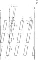
- FIG. 1 rotates in a housing 1, a shaft 2, on which disc elements 3 are arranged. These disc elements 3 are transport bars 4 are placed, which strip a housing inner wall.
- the transport bars 4 and disc elements 3 cooperate with static installations 5 which protrude from the housing inner wall into a product space 8 against the shaft 2.
- Dash-dotted with 12 is a sectional plane with view direction for the following FIGS. 2 to 4 indicated.
- the shaft 2 rotates about a shaft axis A.
- Each transport bar 4 has a central axis B which extends through a center M of the transport bar 4.
- the center axis B is set at an angle to the shaft axis A.
- a surface 9 of the kneading bar 4 extends at an angle 7, which is to be referred to as the conveying angle.
- the surface 9 extends approximately parallel to the central axis B.
- the surfaces 9 of successive transport bars 4 are each offset by a certain amount a or b in the circumferential direction, so that they take effect at different times in the product.
- the product space 8 is filled in a kneader only to a certain extent, while the remaining part is designed product-free as a free space.
- the transport bar 4.1 first emerges from the product, but after a certain rotation, it is the first to encounter the product in the product space 8 again. With a time delay, the transport bar follows him 4.2 and this in turn delayed the transport bar 4.3. As a result, both the product treatment, as well as the conveying speed, and the power consumption of the shaft is influenced.
- 6 denotes a development angle. This is the placement angle of the billets between successive rows of disks.
- the unwinding angle 6 corresponds to the conveying angle 7.
- Each transport bar is subdivided into sections 10.1 and 10.2, which are arranged staggered in relation to each other.
- the central axes of the mutually facing sections of successive transport bars the same angle to the shaft axis.
- the unwinding angle 6 and the conveying angle 7 is indicated, also an angle 11 of two mutually facing portions of successive transport bars.
Description
Die Erfindung betrifft einen Mischkneter nach dem Oberbegriff von Anspruch 1.The invention relates to a mixing kneader according to the preamble of
In der Verfahrenstechnik sind gerührte Behälter zur Reaktionsführung oder für thermische Prozesse seit langem üblich. Wird der Rührbehälter kontinuierlich betrieben, ist es wünschenswert den Füllgrad im Rührbehälter einstellen zu können, da der Kessel sonst über- oder unterfüllen kann oder das Edukt oder Produkt im Rührbehälter unterschiedlichen Verweilzeit ausgesetzt wäre. Die Einstellung des Füllgrades erfolgt gravimetrisch entweder über ein Wehr, über welches das Produkt überläuft, oder mittels einer Pumplösung mit Füllstandssonde.In process engineering, stirred vessels have been used for a long time to conduct reactions or for thermal processes. If the stirred tank is operated continuously, it is desirable to be able to adjust the degree of filling in the stirred tank, since otherwise the boiler may over- or underfill or the educt or product in the stirred tank would be exposed to a different residence time. The The degree of filling is adjusted gravimetrically either via a weir, over which the product overflows, or by means of a pump solution with level probe.
Bei viskosen Massen oder Pasten funktioniert die gravimetrische Füllstandkontrolle nicht, da der Rührer so ausgestaltet sein muss, dass er das Produkt oder Edukt zwangsfördert. Die Kräfte, die bei der Zwangsförderung entstehen, sind dabei grösser als die Gravitationskräfte und damit bestimmend, wie hoch der Füllgrad im Rührbehälter ist. Ein übliches Beispiel ist eine Förderschnecke, wie z.B. in der
Ein Nachteil der Förderschnecke ist, dass die Förderleistung mit dem Durchmesser der Schnecke quadratisch zunimmt. Soll ein grosser Rührbehälter gebaut werden, heisst das, dass die Schneckensteigung sehr klein sein muss, um einen hohen Füllgrad einzustellen. Damit wird die Welle sehr voluminös und schwer, vor allem, wenn sie selbstreinigend sein soll, wie es bei einigen Zweiwellenschnecken der Fall ist. Alternativ muss die Drehzahl stark zurückgenommen werden, was die Rührleistung des Rührbehälters stark einschränkt.
Soll der Füllgrad im Schneckenraum zusätzlich erhöht werden, kann der Rückfluss von der Rückseite her gestaut werden. Die Schnecke läuft dann vor dem Staupunkt voll, so dass es zu einem Rückfluss in der Schnecke kommt. Der Rückfluss und die durch den erhöhten Füllgrad erhöhte Förderleistung gleichen sich exakt aus. Die Schnecke baut dann gemäss dem Druckgefälle des Rückstroms in Förderrichtung Druck auf, welcher der Stauung entgegenwirkt. Es wird somit ein erhöhter Füllgrad in der Schnecke erreicht, der allerdings inhomogen ist, da im Einzugsbereich ein niedriger Füllgrad gegeben, aber vor der Stauung über eine bestimmte Länge die Schnecke zu 100 % gefüllt ist. Auch wird durch diese Methode sehr viel Energie in das Produkt dissipiert.A disadvantage of the screw conveyor is that the delivery rate increases quadratically with the diameter of the screw. If a large stirred tank to be built, that means that the screw pitch must be very small in order to set a high degree of filling. This makes the shaft very voluminous and heavy, especially if it is to be self-cleaning, as is the case with some twin-screw augers. Alternatively, the speed must be greatly reduced, which greatly limits the stirring power of the stirred tank.
If the degree of filling in the screw space is to be additionally increased, the return flow can be stowed from the rear side. The screw then runs full before the stagnation point, so that it comes to a backflow in the screw. The reflux and the increased through the increased degree of filling equalize exactly. The screw then builds up according to the pressure drop of the return flow in the conveying direction pressure, which is the stowage counteracts. It is thus achieved an increased degree of filling in the screw, which is, however, inhomogeneous, as given in the catchment area, a low degree of filling, but before the stowage over a certain length, the screw is filled to 100%. Also, this method dissipates a lot of energy into the product.
Die Schnecke kann nun so gebaut werden, dass sie effizienter Druck aufbaut, indem die Scherspalte verringert werden. Dann wird weniger mechanische Verlustleistung erzeugt. Damit wird der Bereich der 100 % gefüllten Schnecke aber kürzer und das Ziel einer effizienten Füllgradregelung ist wieder nicht erfüllt.The auger can now be built to more efficiently build pressure by reducing the shear gaps. Then less mechanical power loss is generated. However, the range of the 100% filled screw is shorter and the goal of an efficient filling level control is again not fulfilled.
Um die Situation der Füllgradregelung zu verbessern, wurden grossvolumige Kneter (im folgenden Kneter genannt) entwickelt. Derartige Vorrichtungen werden auch als Mischkneter bezeichnet. Sie dienen sehr vielfältige Zwecken. Als erstes ist das Eindampfen mit Lösungsmittelrückgewinnung zu erwähnen, welches chargenweise oder kontinuierlich und oft auch unter Vakuum erfolgt. Hierdurch werden beispielsweise Destillationsrückstände und insbesondere Toluoldiisocyanate behandelt, aber auch Produktionsrückstände mit toxischen oder hochsiedenden Lösungsmitteln aus der Chemie und Pharmaproduktion, Waschlösungen und Lack-Schlämme, Polymerlösungen, Elastomerlösungen aus der Lösemittelpolymerisation, Klebstoffe und Dichtmassen.In order to improve the situation of filling level control, large-volume kneaders (called kneaders in the following) were developed. Such devices are also referred to as mixing kneader. They serve very diverse purposes. First of all mention should be made of evaporation with solvent recovery, which is carried out batchwise or continuously and often under vacuum. As a result, for example, distillation residues and in particular toluene diisocyanates are treated, but also production residues with toxic or high-boiling solvents from chemistry and pharmaceutical production, washing solutions and paint sludge, polymer solutions, elastomer solutions from the solvent, adhesives and sealants.
Mit den Apparaten wird ferner eine kontinuierliche oder chargenweise Kontakttrocknung, Wasser- und/oder lösemittelfeuchter Produkte, oftmals ebenfalls unter Vakuum, durchgeführt. Die Anwendung ist vor allem gedacht für Pigmente, Farbstoffe, Feinchemikalien, Additive, wie Salze, Oxyde, Hydroxyde, Antioxydantien, temperaturempfindliche Pharma- und Vitaminprodukte, Wirkstoffe, Polymere, synthetische Kautschuke, Polymersuspensionen, Latex, Hydrogele, Wachse, Pestizide und Rückstände aus der chemischen oder pharmazeutischen Produktion, wie Salze, Katalysatoren, Schlacken, Ablaugen gedacht. Anwendung finden diese Verfahren auch in der Lebensmittelproduktion, beispielsweise bei der Herstellung und/oder Behandlung von Blockmilch, Zuckeraustauschstoffen, Stärkederivaten, Alginaten, zur Behandlung von Industrieschlämmen, Ölschlämmen, Bioschlämmen, Papierschlämmen, Lackschlämmen und allgemein zur Behandlung von klebrigen, krustenden zähpastösen Produkte, Abfallprodukten und Zellulosederivaten.With the apparatuses is also a continuous or batchwise contact drying, water and / or solvent-moist products, often also under vacuum, performed. The application is intended primarily for pigments, dyes, fine chemicals, additives such as salts, oxides, hydroxides, antioxidants, temperature-sensitive pharmaceutical and vitamin products, active ingredients, polymers, synthetic rubbers, polymer suspensions, latex, hydrogels, waxes, pesticides and residues from the chemical or pharmaceutical production, such as salts, catalysts, slags, waste liquors. These methods are also used in the Food production, for example in the production and / or treatment of block milk, sugar substitutes, starch derivatives, alginates, for the treatment of industrial sludges, oil sludges, biosludges, paper sludges, paint sludges and generally for the treatment of sticky, crusting tough paste products, waste products and cellulose derivatives.
In Mischknetern kann ein Entgasen und/oder Devolatilisieren stattfinden. Angewendet wird dies auf Polymerschmelzen, nach Kondensation von Polyester oder Polyamidschmelzen, auf Spinnlösungen für synthetische Fasern und auf Polymer- oder Elastomergranulate bzw. -pulver im festen Zustand.In mixing kneaders, degassing and / or devolatilization may take place. This is applied to polymer melts, after condensation of polyester or polyamide melts, on spinning solutions for synthetic fibers and on polymer or elastomer granules or powder in the solid state.
In einem Mischkneter kann eine Polykondensationsreaktion, meist kontinuierlich und meist in der Schmelze, stattfinden und wird vor allem verwendet bei der Behandlung von Polyamiden, Polyester, Polyacetaten, Polyimide, Thermoplaste, Elastomere, Silikone, Harnstoffharze, Phenolharze, Detergentien und Düngemittel.In a mixing kneader, a polycondensation reaction, usually continuous and usually in the melt, take place and is mainly used in the treatment of polyamides, polyesters, polyacetates, polyimides, thermoplastics, elastomers, silicones, urea resins, phenolic resins, detergents and fertilizers.
Stattfinden kann auch eine Polymerisationsreaktion, ebenfalls meist kontinuierlich. Dies wird angewendet auf Polyakrylate, Hydrogele, Polyole, thermoplastische Polymere, Elastomere, syndiotaktisches Polysterol und Polyacrylamide.It is also possible to carry out a polymerization reaction, likewise usually continuously. This is applied to polyacrylates, hydrogels, polyols, thermoplastic polymers, elastomers, syndiotactic polystyrene and polyacrylamides.
Ganz allgemein können im Mischkneter Reaktionen fest, flüssig und mehrphasige Reaktionen stattfinden. Dies gilt vor allem für Backreaktionen, bei der Behandlung von Flusssäure, Stearaten, Zyanaten, Polyphosphaten, Cyanursäuren, Zellulosederivaten, -ester, -äther, Polyacetalharzen, Sulfanilsäuren, Cu-Phthalocyaninen, Stärkederivaten, Ammoniumpolyphosphaten, Sulfonaten, Pestiziden und Düngemittel.In general, reactions in the mixing kneader can take place in solid, liquid and multiphase reactions. This is especially true for baking reactions, in the treatment of hydrofluoric acid, stearates, cyanates, polyphosphates, cyanuric acids, cellulose derivatives, esters, ethers, polyacetal resins, sulphanilic acids, copper phthalocyanines, starch derivatives, ammonium polyphosphates, sulfonates, pesticides and fertilizers.
Des weiteren können Reaktionen fest-/gasförmig (z.B. Karboxylierung) oder flüssig-/gasförmig stattfinden. Angewendet wird dies bei der Behandlung von Acetaten, Aciden, Kolbe-Schmitt-Reaktionen, z.B. BON, Na-Salicylaten, Parahydroxibenzoaten und Pharmaprodukten.Furthermore, reactions can take place solid / gaseous (eg carboxylation) or liquid / gaseous. This is used in the treatment of Acetates, Acids, Kolbe-Schmitt reactions, eg BON, Na salicylates, parahydroxibenzoates and pharmaceutical products.
Reaktionen flüssig/flüssig erfolgen bei Neutralisationsreaktionen und Umesterungsreaktionen.Reactions liquid / liquid occur in neutralization reactions and transesterification reactions.
Ein Lösen und/oder Entgasen in derartigen Mischknetern findet bei Spinnlösungen für synthetische Fasern, Polyamiden, Polyester und Zellulosen statt.Dissolving and / or degassing in such mixing kneaders takes place in spinning solutions for synthetic fibers, polyamides, polyesters and celluloses.
Ein sogenanntes Flushen findet bei der Behandlung bzw. Herstellung von Pigmenten statt.A so-called Flushing takes place in the treatment or production of pigments.
Eine Solid-State- Nachkondensation findet bei der Herstellung bzw. Behandlung von Polyester und Polyamiden statt, ein kontinuierliches Anmeischen z.B. bei der Behandlung von Fasern, z.B. Zellulosefasern mit Lösungsmitteln, eine Kristallisation aus der Schmelze oder aus Lösungen bei der Behandlung von Salzen, Feinchemikalien, Polyolen, Alkoholaten, ein Compoundieren, Mischen (kontinuierlich und/oder chargenweise) bei Polymeren-Mischungen, Silikonmassen, Dichtmassen, Flugasche, ein Coagulieren (insbesondere kontinuierlich) bei der Behandlung von Polymersuspensionen.Solid-state post-condensation takes place in the preparation or treatment of polyesters and polyamides, continuous picking, e.g. in the treatment of fibers, e.g. Cellulose fibers with solvents, a melt crystallization or solutions in the treatment of salts, fine chemicals, polyols, alcoholates, compounding, mixing (continuous and / or batchwise) in polymer blends, silicone compositions, sealants, fly ash, coagulation (in particular continuous) in the treatment of polymer suspensions.
In einem Mischkneter können auch multifunktionale Prozesse kombiniert werden, beispielsweise Erhitzen, Trocknen, Schmelzen, Kristallisieren, Mischen, Entgasen, Reagieren - dies alles kontinuierlich oder chargenweise. Hergestellt bzw. behandelt werden dadurch Polymere, Elastomere, anorganische Produkte, Rückstände, Pharmaprodukte, Lebensmittelprodukte, Druckfarben.In a mixing kneader also multifunctional processes can be combined, for example heating, drying, melting, crystallizing, mixing, degassing, reacting - all this continuously or in batches. This produces and / or treats polymers, elastomers, inorganic products, residues, pharmaceutical products, food products, printing inks.
In Mischknetern kann auch eine Vakuumsublimation/ Desublimation stattfinden, wodurch chemische Vorprodukte, z.B. Anthrachinon, Metallchloride, metallorganische Verbindungen usw. gereinigt werden. Ferner können pharmazeutische Zwischenprodukte hergestellt werden.In mixed kneaders, a vacuum sublimation / desublimation can take place, whereby chemical precursors, eg anthraquinone, metal chlorides, organometallic compounds, etc. are cleaned. Furthermore, pharmaceutical intermediates can be prepared.
Eine kontinuierliche Trägergas-Desublimation findet z.B. bei organischen Zwischenprodukten, z.B. Antrachinon und Feinchemikalien statt.Continuous carrier gas desublimation finds e.g. for organic intermediates, e.g. Antrachinone and fine chemicals take place.
Im wesentlichen werden einwellige und zweiwellige Mischkneter unterschieden. Ein einwelliger Mischkneter wird beispielsweise in der
Die Wellen drehen meist in horizontaler Anordnung in einem Gehäuse, wobei auf der zylindrischen Kernwelle Scheibensegmente angeordnet sind. Die Form der Scheibensegmente ist so gestaltet, dass sie so unterbrochen sind, dass Segmentleeräume entstehen, wodurch das Produkt in Wellenrichtung fliessen kann. Auf den Scheibensegmenten sind Förderelemente befestigt, die Barren oder auch Transportbarren genannt werden.The shafts usually rotate in a horizontal arrangement in a housing, wherein disc segments are arranged on the cylindrical core shaft. The shape of the disk segments is designed so that they are interrupted so that there are gaps between the segments, allowing the product to flow in the direction of the waves. On the disc segments conveyor elements are fixed, the ingots or transport bars are called.
Bei einwelligen Knetern werden in dem Gehäuse statische Einbauten befestigt, so dass Scheibensegmente, Barren und statische Einbauten durch die kinematische Bewegung der Welle sich regelmässig begegnen. Bei mehrwelligen Knetern finden die Begegnungen zwischen den Scheibenelementen und Barren der Gegenwelle statt. Die Scheibensegmente können auf der Welle versetzt sein und mögen eine definierte Form haben, die der kinematischen Bewegung der Gegenwelle folgt. Es gibt eine Vielzahl von geometrischen Möglichkeiten, solche Kneter zu bauen.In the case of single-shaft kneaders, static installations are fastened in the housing so that disk segments, ingots and static installations regularly meet through the kinematic movement of the shaft. In the case of multi-shaft kneaders, the encounters between the disc elements and bars of the countershaft take place. The disk segments may be offset on the shaft and may have a defined shape following the kinematic motion of the countershaft. There are a variety of geometric ways to build such kneaders.
Die Konstruktion der Kneter wurde historisch von Schneckenmaschinen abgeleitet. Man hat daher die Flankenkante der Barren, ähnlich wie bei Schneckenapparaten, fluchtend angeordnet. Damit der Kneter in eine gewünschte Richtung fördert, werden die Barren auf den Scheibensegmenten mit einem Winkel angeordnet, der von der Idee her den Flankenwinkel von Schneckenwellen entspricht. Es wird davon ausgegangen, dass die Förderlogik den von Schneckenmaschinen ähnlich ist, wenn auch schnell deutlich wird, dass es grosse Abweichungen gibt. So ist die Möglichkeit, höhere Füllgrade bei schnelleren Drehzahlen zu erreichen, gegenüber Schneckenapparaten erheblich verbessert. Der Füllgrad lässt sich von der Rückseite über eine Austragsschnecke einstellen, ohne dass der Kneter in diesem Bereich sich zu 100 % füllt. Im Gegenteil ist der Füllgradverlauf recht homogen über die Länge und steigt eher linear an oder fällt ab, aber nie abrupt, es sei denn die rheologischen Eigenschaften des Produktes ändern sich ebenfalls abrupt.The construction of kneaders has historically been derived from screw machines. Therefore, the flank edge of the ingots has been aligned in a manner similar to screw apparatuses. So that the kneader conveys in a desired direction, the ingots are arranged on the disc segments at an angle which corresponds to the idea of the flank angle of worm shafts. It is assumed that the production logic is similar to that of screw machines, although it quickly becomes clear that there are large deviations. Thus, the ability to achieve higher fill levels at faster speeds, compared to augers significantly improved. The filling level can be adjusted from the rear using a discharge screw without the kneader filling up to 100% in this area. On the contrary, the filling degree curve is quite homogeneous over the length and tends to increase or decrease linearly, but never abruptly, unless the rheological properties of the product also change abruptly.
Die fluchtende Anordnung der Barren ergibt sich somit aus der Analogie zur Schneckengeometrie, dass nämlich Wandreibung zum Transport notwendig ist. In der Publikation "
Aus dem Stand der Technik ist eine Anstellung der Barren gegenüber der Wellenachse hinreichend bekannt. Dies wird beispielsweise in der
In der
Aus der
Aufgabe der vorliegenden Erfindung ist es, bisher bekannte Kneter bezüglich der Produktbehandlung und der Förderleistung zu verbessern und bezüglich des zu behandelnden Produkts flexibler auszugestalten.The object of the present invention is to improve previously known kneaders with regard to the product treatment and the delivery rate and to make them more flexible with respect to the product to be treated.
Zur Lösung der Aufgabe führen die Merkmale des kennzeichnenden Teils von Anspruch 1.To achieve the object, the features of the characterizing part of
Eine wichtige Voraussage des Transportmodells der o.g. Publikation ist, dass die fluchtende Anordnung der Knet- oder Transportbarren für die Fördercharakteristik bei viskosen Massen und Pasten nicht zwingend ist. Geometrisch wird diese einzig durch den Anstellwinkel des Barren beeinflusst. Wenn dem so ist, kann der Anstellwinkel der Barren und der Anordnungswinkel der Barren zwischen aufeinander folgenden Scheibenreihen (der sogenannte Abwicklungswinkel) entkoppelt werden. Gegenstand sind daher vor allem Anordnungen, wo der Anstellwinkel und der Abwicklungswinkel nicht identisch sind. Dies hat den Vorteil, dass der Anstellwinkel entsprechend einer geforderten Fördercharakteristik des Kneters und der Abwicklungswinkel z.B. entsprechend einer gewünschten Eingriffskraftverteilung über die Drehbewegung der Welle bestimmt werden kann.An important prediction of the transport model of the above-mentioned publication is that the alignment of the kneading or transport ingots for the conveying characteristic is not mandatory for viscous masses and pastes. Geometrically, this is influenced only by the angle of attack of the ingot. If so, the angle of attack of the billets and the arrangement angle of the ingot between successive rows of discs (the so-called unwinding angle) can be decoupled. The object is therefore primarily arrangements where the angle of attack and the unwinding angle are not identical. This has the advantage that the angle of attack can be determined according to a required conveying characteristic of the kneader and the unwinding angle, for example, according to a desired engagement force distribution over the rotational movement of the shaft.
Es ist daran gedacht, den Winkel der Transportbarren mit der Wellenachse unterschiedlich zum Winkel zwischen den Mittelpunkten der Barren, die sich entlang der Wellenachse folgen, auszugestalten. Der Anstellwinkel, den die einzelnen Transportbarren mit der Wellenachse bilden, kann zumindest teilweise unterschiedlich ist.It is intended to design the angle of the transport bar with the shaft axis different from the angle between the centers of the bars following along the shaft axis. The angle of attack, which form the individual transport bar with the shaft axis, may be at least partially different.
Bei einwelligen Knetern lässt sich der Abwicklungswinkel und der Anstellwinkel beliebig entkoppeln. Ein konstruktives Erschwernis ergibt sich nicht. Bei mehrwelligen Knetern muss beachtet werden, dass die eingreifenden Elemente nicht tangential in der Wellenbewegung eingreifen, sondern in die Wellenbewegung der Gegenwelle eintauchen und nach einem bestimmten Drehwinkel wieder austreten. Eine Verdrehung der Barren gegenüber der Abwicklung der Welle ist daher nicht möglich, wenn der Kneter mit minimalen Spielen zwischen den drehenden Elementen gebaut wurde. Erfindungsgemäss wird dieses Problem so gelöst, dass der Barren in mindestens zwei Abschnitte aufgeteilt wird, die jeweils den gewünschten Barrenanstellwinkel aufweisen, wobei der Abwicklungswinkel beliebig gewählt werden kann. Die beiden Barrenhälften einer Mischkammer, die auf einander folgenden Scheiben montiert sind, bilden dabei eine Linie, so dass das Spiel zwischen den Wellenelementen wieder minimal ist.With single-shaft kneaders, the unwinding angle and the angle of attack can be decoupled as desired. A constructive difficulty does not arise. In the case of multi-shaft kneaders, it must be ensured that the engaging elements do not engage tangentially in the shaft movement, but instead immerse themselves in the wave motion of the countershaft and exit again after a certain angle of rotation. A twisting of the bars compared to the development of the shaft is therefore not possible if the kneader was built with minimal play between the rotating elements. According to the invention, this problem is solved in such a way that the billet is divided into at least two sections, each of which has the desired bar setting angle, wherein the unwinding angle can be chosen as desired. The two bar halves of a mixing chamber, which are mounted on successive discs, thereby forming a line, so that the game between the shaft elements is again minimal.
Weitere Vorteile, Merkmale und Einzelheiten ergeben sich aus der nachfolgenden Beschreibung bevorzugter Ausführungsbeispiele sowie anhand der Zeichnung; diese zeigt in
-
Figur 1 -
Figur 2 -
Figur 3Figur 1 ; -
Figur 4Figur 1 .
-
FIG. 1 a schematically illustrated cross section through a kneader; -
FIG. 2 a partially illustrated processing of transport bars; -
FIG. 3 a partially illustrated execution of another arrangement of transport bars for a kneader according toFIG. 1 ; -
FIG. 4 a partially illustrated processing of an embodiment according to the invention of transport bars for a kneader according toFIG. 1 ,
Gemäss
Die Transportbarren 4 und Scheibenelemente 3 wirken mit statischen Einbauten 5 zusammen, die von der Gehäuseinnenwand in einen Produktraum 8 gegen die Welle 2 einragen.The transport bars 4 and
Strichpunktiert ist mit 12 eine Schnittebene mit Ansichtsrichtung für die nachfolgenden
Die Welle 2 dreht um eine Wellenachse A. Jeder Transportbarren 4 besitzt eine Mittelachse B, die durch einen Mittelpunkt M des Transportbarrens 4 verläuft. Die Mittelachse B ist in einem Winkel gegen die Wellenachse A angestellt.The
Eine Oberfläche 9 des Knetbarrens 4 verläuft in einem Winkel 7, der als Förderwinkel zu bezeichnen ist. Im Beispiel gemäss
Mit 6 wird im übrigen ein Abwicklungswinkel bezeichnet. Dies ist der Anordnungswinkel der Barren zwischen aufeinanderfolgenden Scheibenreihen. Im Ausführungsbeispiel gemäss
Anders ist dies dagegen in
In dem Ausführungsbeispiel der Erfindung gemäss
Claims (2)
- A mixing kneader for the controlled transportation of viscous substances and pastes in at least one processing chamber (8) by means of at least one shaft (8) on which there are arranged disc elements (3) with attached transport bars (4) and which rotates about a shaft axis (A), wherein central axes (B) of the transport bars (4) run at an angle (7) to the shaft axis (A),
characterized in that
the transport bars (4) are divided into two or more portions (10.1, 10.2) arranged in a step-shaped manner and the central axes (B) of transport bars (4) successive in the direction of the shaft axis (A) run staggered in relation to one another in the circumferential direction. - A mixing kneader according to claim 1, characterized in that the central axes of the portions (10.1, 10.2) of successive transport bars (4) run at the same angle to the shaft axis (A).
Applications Claiming Priority (2)
| Application Number | Priority Date | Filing Date | Title |
|---|---|---|---|
| DE102012103565A DE102012103565A1 (en) | 2012-04-24 | 2012-04-24 | Device for transporting viscous masses and pastes |
| PCT/EP2013/058143 WO2013160196A1 (en) | 2012-04-24 | 2013-04-19 | Device for transporting viscous compounds and pastes |
Publications (2)
| Publication Number | Publication Date |
|---|---|
| EP2841190A1 EP2841190A1 (en) | 2015-03-04 |
| EP2841190B1 true EP2841190B1 (en) | 2016-08-03 |
Family
ID=48463925
Family Applications (1)
| Application Number | Title | Priority Date | Filing Date |
|---|---|---|---|
| EP13723420.9A Active EP2841190B1 (en) | 2012-04-24 | 2013-04-19 | Device for transporting viscous compounds and pastes |
Country Status (8)
| Country | Link |
|---|---|
| US (1) | US20150131401A1 (en) |
| EP (1) | EP2841190B1 (en) |
| JP (1) | JP6278362B2 (en) |
| KR (1) | KR102127020B1 (en) |
| CN (1) | CN104245107B (en) |
| DE (1) | DE102012103565A1 (en) |
| IN (1) | IN2014MN01894A (en) |
| WO (1) | WO2013160196A1 (en) |
Families Citing this family (1)
| Publication number | Priority date | Publication date | Assignee | Title |
|---|---|---|---|---|
| US11780141B1 (en) * | 2018-12-04 | 2023-10-10 | The United States Of America As Represented By The Secretary Of The Army | Continuous process for producing foamable celluloid |
Family Cites Families (23)
| Publication number | Priority date | Publication date | Assignee | Title |
|---|---|---|---|---|
| US925744A (en) * | 1909-03-11 | 1909-06-22 | Perry L Blystone | Mortar-mixer. |
| US1199721A (en) * | 1915-11-10 | 1916-09-26 | Francis W Tully | Glove-stretcher. |
| GB1199721A (en) * | 1966-06-30 | 1970-07-22 | Nii Shinnoi Promy | Device for Continuous Preparation of Mixtures |
| CH506322A (en) | 1969-03-17 | 1971-04-30 | List Heinz | Multi-spindle mixing and kneading machine |
| DE2123956C3 (en) * | 1970-05-20 | 1979-09-20 | Heinz Dipl.-Ing. Pratteln List (Schweiz) | Mixing and kneading machine |
| CH583061A5 (en) * | 1972-10-18 | 1976-12-31 | List Heinz | |
| CH558512A (en) * | 1972-11-21 | 1975-01-31 | List Heinz | HEAT EXCHANGER. |
| US4039024A (en) * | 1972-11-21 | 1977-08-02 | Heinz List | Heat exchanger |
| DE3474503D1 (en) * | 1983-12-05 | 1988-11-17 | List Ind Verfahrenstech | Mixing and kneading machine |
| CH672749A5 (en) * | 1986-12-19 | 1989-12-29 | List Ag | |
| EP0274668B1 (en) * | 1986-12-19 | 1992-07-22 | List AG | Kneading mixer |
| CH674472A5 (en) * | 1987-05-06 | 1990-06-15 | List Ag | |
| CH680196A5 (en) * | 1988-02-16 | 1992-07-15 | List Ag | |
| JPH01148731U (en) * | 1988-04-05 | 1989-10-16 | ||
| CH686406A5 (en) | 1990-04-11 | 1996-03-29 | List Ag | Continuously operating mixing kneader. |
| DE4118884A1 (en) * | 1991-06-07 | 1992-12-10 | List Ag | MIXING kneader |
| US5519470A (en) * | 1994-03-04 | 1996-05-21 | Xerox Corporation | Cross mixing paddle wheel |
| DE19536944A1 (en) * | 1995-10-04 | 1997-04-10 | List Ag | Mixer kneader |
| DE19940521C2 (en) | 1999-08-26 | 2003-02-13 | List Ag Arisdorf | mixing kneader |
| US20040145964A1 (en) * | 2001-04-25 | 2004-07-29 | Alfred Kunz | Mixer bars cleaning in a radial or axial manner |
| DE10160535A1 (en) | 2001-12-10 | 2003-06-18 | List Ag | Mixer-kneading device used e.g. for treating distillation residues comprises mixing elements arranged on shafts extending in the longitudinal direction of the shaft or slightly inclined and having a scraping edge |
| ES2321412T3 (en) * | 2005-04-20 | 2009-06-05 | Buss-Sms-Canzler Gmbh | LARGE VOLUME MIXER / REACTOR. |
| DE102008048580B4 (en) * | 2008-09-23 | 2014-08-21 | List Holding Ag | Device for carrying out mechanical, chemical and / or thermal processes |
-
2012
- 2012-04-24 DE DE102012103565A patent/DE102012103565A1/en not_active Withdrawn
-
2013
- 2013-04-19 CN CN201380020355.0A patent/CN104245107B/en active Active
- 2013-04-19 EP EP13723420.9A patent/EP2841190B1/en active Active
- 2013-04-19 KR KR1020147028381A patent/KR102127020B1/en active IP Right Grant
- 2013-04-19 WO PCT/EP2013/058143 patent/WO2013160196A1/en active Application Filing
- 2013-04-19 JP JP2015507477A patent/JP6278362B2/en active Active
- 2013-04-19 US US14/396,262 patent/US20150131401A1/en not_active Abandoned
-
2014
- 2014-09-23 IN IN1894MUN2014 patent/IN2014MN01894A/en unknown
Also Published As
| Publication number | Publication date |
|---|---|
| US20150131401A1 (en) | 2015-05-14 |
| KR102127020B1 (en) | 2020-07-09 |
| JP2015515378A (en) | 2015-05-28 |
| JP6278362B2 (en) | 2018-02-14 |
| WO2013160196A1 (en) | 2013-10-31 |
| CN104245107A (en) | 2014-12-24 |
| KR20150003732A (en) | 2015-01-09 |
| DE102012103565A1 (en) | 2013-10-24 |
| EP2841190A1 (en) | 2015-03-04 |
| IN2014MN01894A (en) | 2015-07-10 |
| CN104245107B (en) | 2016-05-18 |
Similar Documents
| Publication | Publication Date | Title |
|---|---|---|
| EP2900358B1 (en) | Mixing kneader for implementing mechanical, chemical and/or thermal processes | |
| EP2800622B1 (en) | Device for carrying out mechanical, chemical, and/or thermal processes | |
| EP1436073B1 (en) | Kneader | |
| EP2328677B1 (en) | Device for carrying out mechanical, chemical and/or thermal processes | |
| DE10160535A1 (en) | Mixer-kneading device used e.g. for treating distillation residues comprises mixing elements arranged on shafts extending in the longitudinal direction of the shaft or slightly inclined and having a scraping edge | |
| WO2002089963A2 (en) | Mixer bars cleaning in a radial or axial manner | |
| EP2464763B1 (en) | Method for treating a monomer, pre-polymer, polymer or a corresponding mixture | |
| EP2841190B1 (en) | Device for transporting viscous compounds and pastes | |
| DE102012108261B4 (en) | Mixing kneader for the treatment of viscous or pasty products in a product room | |
| WO2015104264A1 (en) | Device for treating a product in a housing | |
| WO2015169827A2 (en) | Device and method for carrying out mechanical, chemical and/or thermal processes | |
| WO2002068106A1 (en) | Method and device for mixing products | |
| EP2872800A1 (en) | Method and apparatus for handling a product | |
| DE102012106237A1 (en) | Mixing kneader for the treatment of viscous or pasty products in a product room | |
| DE10120391A1 (en) | Mixer-kneading device used e.g. for treating distillation residues comprises mixing elements arranged on shafts extending in the longitudinal direction of the shaft or slightly inclined and having a scraping edge | |
| DE102014113882A1 (en) | Device for transporting compact polymer masses | |
| DE102014112268A1 (en) | Device for transporting compact polymer masses | |
| DE102012112162B4 (en) | basket reactor | |
| EP2812109A1 (en) | Method for performing mechanical, chemical and/or thermal processes | |
| DE102012110118A1 (en) | Carrying out mechanical, chemical or thermal process comprises adding reactant or product and catalyst in housing having feed point, through which the product to desired degree of conversion reacts | |
| DE102015107027A1 (en) | Apparatus and method for carrying out mechanical, chemical and / or thermal processes | |
| DE10202435A1 (en) | Mixer-kneading device used e.g. for treating distillation residues comprises mixing elements arranged on shafts extending in the longitudinal direction of the shaft or slightly inclined and having a scraping edge | |
| DE102012107255A1 (en) | Device e.g. kneading against hook for performing mechanical, chemical and thermal processes in product, has mixing element, cleaning element and transport element whose specific portions are coordinated with peripheral edge of product | |
| DE102014004222A1 (en) | Method for carrying out mechanical, chemical and / or thermal processes |
Legal Events
| Date | Code | Title | Description |
|---|---|---|---|
| PUAI | Public reference made under article 153(3) epc to a published international application that has entered the european phase |
Free format text: ORIGINAL CODE: 0009012 |
|
| 17P | Request for examination filed |
Effective date: 20141112 |
|
| AK | Designated contracting states |
Kind code of ref document: A1 Designated state(s): AL AT BE BG CH CY CZ DE DK EE ES FI FR GB GR HR HU IE IS IT LI LT LU LV MC MK MT NL NO PL PT RO RS SE SI SK SM TR |
|
| AX | Request for extension of the european patent |
Extension state: BA ME |
|
| DAX | Request for extension of the european patent (deleted) | ||
| GRAP | Despatch of communication of intention to grant a patent |
Free format text: ORIGINAL CODE: EPIDOSNIGR1 |
|
| INTG | Intention to grant announced |
Effective date: 20160212 |
|
| GRAS | Grant fee paid |
Free format text: ORIGINAL CODE: EPIDOSNIGR3 |
|
| GRAA | (expected) grant |
Free format text: ORIGINAL CODE: 0009210 |
|
| AK | Designated contracting states |
Kind code of ref document: B1 Designated state(s): AL AT BE BG CH CY CZ DE DK EE ES FI FR GB GR HR HU IE IS IT LI LT LU LV MC MK MT NL NO PL PT RO RS SE SI SK SM TR |
|
| REG | Reference to a national code |
Ref country code: GB Ref legal event code: FG4D Free format text: NOT ENGLISH |
|
| REG | Reference to a national code |
Ref country code: CH Ref legal event code: EP Ref country code: AT Ref legal event code: REF Ref document number: 816979 Country of ref document: AT Kind code of ref document: T Effective date: 20160815 |
|
| REG | Reference to a national code |
Ref country code: IE Ref legal event code: FG4D Free format text: LANGUAGE OF EP DOCUMENT: GERMAN |
|
| REG | Reference to a national code |
Ref country code: DE Ref legal event code: R096 Ref document number: 502013003944 Country of ref document: DE |
|
| REG | Reference to a national code |
Ref country code: CH Ref legal event code: NV Representative=s name: ARIE WUBBEN C/O MEDIPACK AG, CH |
|
| REG | Reference to a national code |
Ref country code: NL Ref legal event code: MP Effective date: 20160803 |
|
| REG | Reference to a national code |
Ref country code: LT Ref legal event code: MG4D |
|
| PG25 | Lapsed in a contracting state [announced via postgrant information from national office to epo] |
Ref country code: FI Free format text: LAPSE BECAUSE OF FAILURE TO SUBMIT A TRANSLATION OF THE DESCRIPTION OR TO PAY THE FEE WITHIN THE PRESCRIBED TIME-LIMIT Effective date: 20160803 Ref country code: RS Free format text: LAPSE BECAUSE OF FAILURE TO SUBMIT A TRANSLATION OF THE DESCRIPTION OR TO PAY THE FEE WITHIN THE PRESCRIBED TIME-LIMIT Effective date: 20160803 Ref country code: NL Free format text: LAPSE BECAUSE OF FAILURE TO SUBMIT A TRANSLATION OF THE DESCRIPTION OR TO PAY THE FEE WITHIN THE PRESCRIBED TIME-LIMIT Effective date: 20160803 Ref country code: NO Free format text: LAPSE BECAUSE OF FAILURE TO SUBMIT A TRANSLATION OF THE DESCRIPTION OR TO PAY THE FEE WITHIN THE PRESCRIBED TIME-LIMIT Effective date: 20161103 Ref country code: HR Free format text: LAPSE BECAUSE OF FAILURE TO SUBMIT A TRANSLATION OF THE DESCRIPTION OR TO PAY THE FEE WITHIN THE PRESCRIBED TIME-LIMIT Effective date: 20160803 Ref country code: IS Free format text: LAPSE BECAUSE OF FAILURE TO SUBMIT A TRANSLATION OF THE DESCRIPTION OR TO PAY THE FEE WITHIN THE PRESCRIBED TIME-LIMIT Effective date: 20161203 Ref country code: LT Free format text: LAPSE BECAUSE OF FAILURE TO SUBMIT A TRANSLATION OF THE DESCRIPTION OR TO PAY THE FEE WITHIN THE PRESCRIBED TIME-LIMIT Effective date: 20160803 |
|
| PG25 | Lapsed in a contracting state [announced via postgrant information from national office to epo] |
Ref country code: PT Free format text: LAPSE BECAUSE OF FAILURE TO SUBMIT A TRANSLATION OF THE DESCRIPTION OR TO PAY THE FEE WITHIN THE PRESCRIBED TIME-LIMIT Effective date: 20161205 Ref country code: GR Free format text: LAPSE BECAUSE OF FAILURE TO SUBMIT A TRANSLATION OF THE DESCRIPTION OR TO PAY THE FEE WITHIN THE PRESCRIBED TIME-LIMIT Effective date: 20161104 Ref country code: LV Free format text: LAPSE BECAUSE OF FAILURE TO SUBMIT A TRANSLATION OF THE DESCRIPTION OR TO PAY THE FEE WITHIN THE PRESCRIBED TIME-LIMIT Effective date: 20160803 Ref country code: PL Free format text: LAPSE BECAUSE OF FAILURE TO SUBMIT A TRANSLATION OF THE DESCRIPTION OR TO PAY THE FEE WITHIN THE PRESCRIBED TIME-LIMIT Effective date: 20160803 Ref country code: ES Free format text: LAPSE BECAUSE OF FAILURE TO SUBMIT A TRANSLATION OF THE DESCRIPTION OR TO PAY THE FEE WITHIN THE PRESCRIBED TIME-LIMIT Effective date: 20160803 Ref country code: SE Free format text: LAPSE BECAUSE OF FAILURE TO SUBMIT A TRANSLATION OF THE DESCRIPTION OR TO PAY THE FEE WITHIN THE PRESCRIBED TIME-LIMIT Effective date: 20160803 |
|
| REG | Reference to a national code |
Ref country code: DE Ref legal event code: R082 Ref document number: 502013003944 Country of ref document: DE Representative=s name: PATENTANWAELTE UND RECHTSANWALT WEISS, ARAT & , DE Ref country code: DE Ref legal event code: R081 Ref document number: 502013003944 Country of ref document: DE Owner name: LIST TECHNOLOGY AG, CH Free format text: FORMER OWNER: LIST HOLDING AG, ARISDORF, CH |
|
| PG25 | Lapsed in a contracting state [announced via postgrant information from national office to epo] |
Ref country code: RO Free format text: LAPSE BECAUSE OF FAILURE TO SUBMIT A TRANSLATION OF THE DESCRIPTION OR TO PAY THE FEE WITHIN THE PRESCRIBED TIME-LIMIT Effective date: 20160803 Ref country code: EE Free format text: LAPSE BECAUSE OF FAILURE TO SUBMIT A TRANSLATION OF THE DESCRIPTION OR TO PAY THE FEE WITHIN THE PRESCRIBED TIME-LIMIT Effective date: 20160803 |
|
| REG | Reference to a national code |
Ref country code: FR Ref legal event code: PLFP Year of fee payment: 5 |
|
| REG | Reference to a national code |
Ref country code: DE Ref legal event code: R097 Ref document number: 502013003944 Country of ref document: DE |
|
| PG25 | Lapsed in a contracting state [announced via postgrant information from national office to epo] |
Ref country code: DK Free format text: LAPSE BECAUSE OF FAILURE TO SUBMIT A TRANSLATION OF THE DESCRIPTION OR TO PAY THE FEE WITHIN THE PRESCRIBED TIME-LIMIT Effective date: 20160803 Ref country code: SM Free format text: LAPSE BECAUSE OF FAILURE TO SUBMIT A TRANSLATION OF THE DESCRIPTION OR TO PAY THE FEE WITHIN THE PRESCRIBED TIME-LIMIT Effective date: 20160803 Ref country code: SK Free format text: LAPSE BECAUSE OF FAILURE TO SUBMIT A TRANSLATION OF THE DESCRIPTION OR TO PAY THE FEE WITHIN THE PRESCRIBED TIME-LIMIT Effective date: 20160803 Ref country code: BG Free format text: LAPSE BECAUSE OF FAILURE TO SUBMIT A TRANSLATION OF THE DESCRIPTION OR TO PAY THE FEE WITHIN THE PRESCRIBED TIME-LIMIT Effective date: 20161103 Ref country code: CZ Free format text: LAPSE BECAUSE OF FAILURE TO SUBMIT A TRANSLATION OF THE DESCRIPTION OR TO PAY THE FEE WITHIN THE PRESCRIBED TIME-LIMIT Effective date: 20160803 |
|
| PLBE | No opposition filed within time limit |
Free format text: ORIGINAL CODE: 0009261 |
|
| STAA | Information on the status of an ep patent application or granted ep patent |
Free format text: STATUS: NO OPPOSITION FILED WITHIN TIME LIMIT |
|
| 26N | No opposition filed |
Effective date: 20170504 |
|
| PG25 | Lapsed in a contracting state [announced via postgrant information from national office to epo] |
Ref country code: SI Free format text: LAPSE BECAUSE OF FAILURE TO SUBMIT A TRANSLATION OF THE DESCRIPTION OR TO PAY THE FEE WITHIN THE PRESCRIBED TIME-LIMIT Effective date: 20160803 |
|
| GBPC | Gb: european patent ceased through non-payment of renewal fee |
Effective date: 20170419 |
|
| REG | Reference to a national code |
Ref country code: IE Ref legal event code: MM4A |
|
| PG25 | Lapsed in a contracting state [announced via postgrant information from national office to epo] |
Ref country code: MC Free format text: LAPSE BECAUSE OF FAILURE TO SUBMIT A TRANSLATION OF THE DESCRIPTION OR TO PAY THE FEE WITHIN THE PRESCRIBED TIME-LIMIT Effective date: 20160803 |
|
| PG25 | Lapsed in a contracting state [announced via postgrant information from national office to epo] |
Ref country code: LU Free format text: LAPSE BECAUSE OF NON-PAYMENT OF DUE FEES Effective date: 20170419 Ref country code: GB Free format text: LAPSE BECAUSE OF NON-PAYMENT OF DUE FEES Effective date: 20170419 |
|
| REG | Reference to a national code |
Ref country code: BE Ref legal event code: MM Effective date: 20170430 |
|
| REG | Reference to a national code |
Ref country code: FR Ref legal event code: PLFP Year of fee payment: 6 |
|
| PG25 | Lapsed in a contracting state [announced via postgrant information from national office to epo] |
Ref country code: IE Free format text: LAPSE BECAUSE OF NON-PAYMENT OF DUE FEES Effective date: 20170419 |
|
| PG25 | Lapsed in a contracting state [announced via postgrant information from national office to epo] |
Ref country code: BE Free format text: LAPSE BECAUSE OF NON-PAYMENT OF DUE FEES Effective date: 20170430 |
|
| REG | Reference to a national code |
Ref country code: FR Ref legal event code: TP Owner name: LIST TECHNOLOGY AG, CH Effective date: 20180821 |
|
| PG25 | Lapsed in a contracting state [announced via postgrant information from national office to epo] |
Ref country code: MT Free format text: LAPSE BECAUSE OF FAILURE TO SUBMIT A TRANSLATION OF THE DESCRIPTION OR TO PAY THE FEE WITHIN THE PRESCRIBED TIME-LIMIT Effective date: 20160803 |
|
| PG25 | Lapsed in a contracting state [announced via postgrant information from national office to epo] |
Ref country code: AL Free format text: LAPSE BECAUSE OF FAILURE TO SUBMIT A TRANSLATION OF THE DESCRIPTION OR TO PAY THE FEE WITHIN THE PRESCRIBED TIME-LIMIT Effective date: 20160803 |
|
| PG25 | Lapsed in a contracting state [announced via postgrant information from national office to epo] |
Ref country code: HU Free format text: LAPSE BECAUSE OF FAILURE TO SUBMIT A TRANSLATION OF THE DESCRIPTION OR TO PAY THE FEE WITHIN THE PRESCRIBED TIME-LIMIT; INVALID AB INITIO Effective date: 20130419 |
|
| PG25 | Lapsed in a contracting state [announced via postgrant information from national office to epo] |
Ref country code: CY Free format text: LAPSE BECAUSE OF FAILURE TO SUBMIT A TRANSLATION OF THE DESCRIPTION OR TO PAY THE FEE WITHIN THE PRESCRIBED TIME-LIMIT Effective date: 20160803 |
|
| PG25 | Lapsed in a contracting state [announced via postgrant information from national office to epo] |
Ref country code: MK Free format text: LAPSE BECAUSE OF FAILURE TO SUBMIT A TRANSLATION OF THE DESCRIPTION OR TO PAY THE FEE WITHIN THE PRESCRIBED TIME-LIMIT Effective date: 20160803 |
|
| PG25 | Lapsed in a contracting state [announced via postgrant information from national office to epo] |
Ref country code: TR Free format text: LAPSE BECAUSE OF FAILURE TO SUBMIT A TRANSLATION OF THE DESCRIPTION OR TO PAY THE FEE WITHIN THE PRESCRIBED TIME-LIMIT Effective date: 20160803 |
|
| REG | Reference to a national code |
Ref country code: DE Ref legal event code: R079 Ref document number: 502013003944 Country of ref document: DE Free format text: PREVIOUS MAIN CLASS: B01F0007040000 Ipc: B01F0027700000 |
|
| P01 | Opt-out of the competence of the unified patent court (upc) registered |
Effective date: 20230530 |
|
| PGFP | Annual fee paid to national office [announced via postgrant information from national office to epo] |
Ref country code: IT Payment date: 20230421 Year of fee payment: 11 Ref country code: FR Payment date: 20230424 Year of fee payment: 11 Ref country code: DE Payment date: 20230628 Year of fee payment: 11 Ref country code: CH Payment date: 20230502 Year of fee payment: 11 |
|
| PGFP | Annual fee paid to national office [announced via postgrant information from national office to epo] |
Ref country code: AT Payment date: 20230420 Year of fee payment: 11 |
|
| REG | Reference to a national code |
Ref country code: AT Ref legal event code: PC Ref document number: 816979 Country of ref document: AT Kind code of ref document: T Owner name: LIST TECHNOLOGY AG, CH Effective date: 20230718 |