EP2841123B1 - Pompe à sang à pulsations - Google Patents
Pompe à sang à pulsations Download PDFInfo
- Publication number
- EP2841123B1 EP2841123B1 EP13719515.2A EP13719515A EP2841123B1 EP 2841123 B1 EP2841123 B1 EP 2841123B1 EP 13719515 A EP13719515 A EP 13719515A EP 2841123 B1 EP2841123 B1 EP 2841123B1
- Authority
- EP
- European Patent Office
- Prior art keywords
- blood
- chamber
- pump
- line
- pulsation
- Prior art date
- Legal status (The legal status is an assumption and is not a legal conclusion. Google has not performed a legal analysis and makes no representation as to the accuracy of the status listed.)
- Active
Links
- 239000008280 blood Substances 0.000 title claims description 89
- 210000004369 blood Anatomy 0.000 title claims description 89
- 230000000541 pulsatile effect Effects 0.000 title description 3
- 238000005086 pumping Methods 0.000 claims description 58
- 210000002216 heart Anatomy 0.000 claims description 39
- 230000010349 pulsation Effects 0.000 claims description 29
- 230000033764 rhythmic process Effects 0.000 claims description 12
- 239000012530 fluid Substances 0.000 claims description 8
- 239000007788 liquid Substances 0.000 claims description 5
- 239000012528 membrane Substances 0.000 claims description 5
- 238000005192 partition Methods 0.000 claims description 3
- 210000001308 heart ventricle Anatomy 0.000 claims 1
- 210000000709 aorta Anatomy 0.000 description 18
- 210000005240 left ventricle Anatomy 0.000 description 14
- 230000002457 bidirectional effect Effects 0.000 description 7
- 230000004048 modification Effects 0.000 description 7
- 238000012986 modification Methods 0.000 description 7
- 230000000747 cardiac effect Effects 0.000 description 5
- 239000007789 gas Substances 0.000 description 5
- 210000001765 aortic valve Anatomy 0.000 description 4
- 230000008901 benefit Effects 0.000 description 4
- 230000017531 blood circulation Effects 0.000 description 4
- 210000005242 cardiac chamber Anatomy 0.000 description 4
- 230000006870 function Effects 0.000 description 4
- 210000001367 artery Anatomy 0.000 description 3
- 230000008859 change Effects 0.000 description 3
- 238000000034 method Methods 0.000 description 3
- 210000000056 organ Anatomy 0.000 description 3
- 230000036772 blood pressure Effects 0.000 description 2
- 230000008602 contraction Effects 0.000 description 2
- 230000000056 copulatory effect Effects 0.000 description 2
- 238000006073 displacement reaction Methods 0.000 description 2
- 230000009977 dual effect Effects 0.000 description 2
- 210000003709 heart valve Anatomy 0.000 description 2
- 238000002513 implantation Methods 0.000 description 2
- 230000002093 peripheral effect Effects 0.000 description 2
- 210000005241 right ventricle Anatomy 0.000 description 2
- 206010007559 Cardiac failure congestive Diseases 0.000 description 1
- 206010020772 Hypertension Diseases 0.000 description 1
- 208000007536 Thrombosis Diseases 0.000 description 1
- 210000001015 abdomen Anatomy 0.000 description 1
- 210000002376 aorta thoracic Anatomy 0.000 description 1
- 230000004872 arterial blood pressure Effects 0.000 description 1
- 230000001174 ascending effect Effects 0.000 description 1
- 230000036770 blood supply Effects 0.000 description 1
- 210000004204 blood vessel Anatomy 0.000 description 1
- 230000027326 copulation Effects 0.000 description 1
- 230000007423 decrease Effects 0.000 description 1
- 230000003247 decreasing effect Effects 0.000 description 1
- 230000001419 dependent effect Effects 0.000 description 1
- 238000011161 development Methods 0.000 description 1
- 230000018109 developmental process Effects 0.000 description 1
- 230000003205 diastolic effect Effects 0.000 description 1
- 230000000916 dilatatory effect Effects 0.000 description 1
- 230000010339 dilation Effects 0.000 description 1
- 238000011038 discontinuous diafiltration by volume reduction Methods 0.000 description 1
- 230000000694 effects Effects 0.000 description 1
- 210000002837 heart atrium Anatomy 0.000 description 1
- 230000004217 heart function Effects 0.000 description 1
- 239000001307 helium Substances 0.000 description 1
- 229910052734 helium Inorganic materials 0.000 description 1
- SWQJXJOGLNCZEY-UHFFFAOYSA-N helium atom Chemical compound [He] SWQJXJOGLNCZEY-UHFFFAOYSA-N 0.000 description 1
- 208000015181 infectious disease Diseases 0.000 description 1
- 230000002458 infectious effect Effects 0.000 description 1
- 230000007774 longterm Effects 0.000 description 1
- 210000004165 myocardium Anatomy 0.000 description 1
- 210000001147 pulmonary artery Anatomy 0.000 description 1
- 230000002441 reversible effect Effects 0.000 description 1
- 239000013589 supplement Substances 0.000 description 1
- 230000001360 synchronised effect Effects 0.000 description 1
- 230000002792 vascular Effects 0.000 description 1
- 230000002861 ventricular Effects 0.000 description 1
Images

Classifications
-
- A—HUMAN NECESSITIES
- A61—MEDICAL OR VETERINARY SCIENCE; HYGIENE
- A61M—DEVICES FOR INTRODUCING MEDIA INTO, OR ONTO, THE BODY; DEVICES FOR TRANSDUCING BODY MEDIA OR FOR TAKING MEDIA FROM THE BODY; DEVICES FOR PRODUCING OR ENDING SLEEP OR STUPOR
- A61M60/00—Blood pumps; Devices for mechanical circulatory actuation; Balloon pumps for circulatory assistance
- A61M60/10—Location thereof with respect to the patient's body
- A61M60/122—Implantable pumps or pumping devices, i.e. the blood being pumped inside the patient's body
- A61M60/126—Implantable pumps or pumping devices, i.e. the blood being pumped inside the patient's body implantable via, into, inside, in line, branching on, or around a blood vessel
- A61M60/148—Implantable pumps or pumping devices, i.e. the blood being pumped inside the patient's body implantable via, into, inside, in line, branching on, or around a blood vessel in line with a blood vessel using resection or like techniques, e.g. permanent endovascular heart assist devices
-
- A—HUMAN NECESSITIES
- A61—MEDICAL OR VETERINARY SCIENCE; HYGIENE
- A61M—DEVICES FOR INTRODUCING MEDIA INTO, OR ONTO, THE BODY; DEVICES FOR TRANSDUCING BODY MEDIA OR FOR TAKING MEDIA FROM THE BODY; DEVICES FOR PRODUCING OR ENDING SLEEP OR STUPOR
- A61M60/00—Blood pumps; Devices for mechanical circulatory actuation; Balloon pumps for circulatory assistance
- A61M60/10—Location thereof with respect to the patient's body
- A61M60/122—Implantable pumps or pumping devices, i.e. the blood being pumped inside the patient's body
- A61M60/165—Implantable pumps or pumping devices, i.e. the blood being pumped inside the patient's body implantable in, on, or around the heart
- A61M60/178—Implantable pumps or pumping devices, i.e. the blood being pumped inside the patient's body implantable in, on, or around the heart drawing blood from a ventricle and returning the blood to the arterial system via a cannula external to the ventricle, e.g. left or right ventricular assist devices
-
- A—HUMAN NECESSITIES
- A61—MEDICAL OR VETERINARY SCIENCE; HYGIENE
- A61M—DEVICES FOR INTRODUCING MEDIA INTO, OR ONTO, THE BODY; DEVICES FOR TRANSDUCING BODY MEDIA OR FOR TAKING MEDIA FROM THE BODY; DEVICES FOR PRODUCING OR ENDING SLEEP OR STUPOR
- A61M60/00—Blood pumps; Devices for mechanical circulatory actuation; Balloon pumps for circulatory assistance
- A61M60/20—Type thereof
- A61M60/247—Positive displacement blood pumps
- A61M60/253—Positive displacement blood pumps including a displacement member directly acting on the blood
- A61M60/268—Positive displacement blood pumps including a displacement member directly acting on the blood the displacement member being flexible, e.g. membranes, diaphragms or bladders
-
- A—HUMAN NECESSITIES
- A61—MEDICAL OR VETERINARY SCIENCE; HYGIENE
- A61M—DEVICES FOR INTRODUCING MEDIA INTO, OR ONTO, THE BODY; DEVICES FOR TRANSDUCING BODY MEDIA OR FOR TAKING MEDIA FROM THE BODY; DEVICES FOR PRODUCING OR ENDING SLEEP OR STUPOR
- A61M60/00—Blood pumps; Devices for mechanical circulatory actuation; Balloon pumps for circulatory assistance
- A61M60/40—Details relating to driving
- A61M60/424—Details relating to driving for positive displacement blood pumps
- A61M60/427—Details relating to driving for positive displacement blood pumps the force acting on the blood contacting member being hydraulic or pneumatic
-
- A—HUMAN NECESSITIES
- A61—MEDICAL OR VETERINARY SCIENCE; HYGIENE
- A61M—DEVICES FOR INTRODUCING MEDIA INTO, OR ONTO, THE BODY; DEVICES FOR TRANSDUCING BODY MEDIA OR FOR TAKING MEDIA FROM THE BODY; DEVICES FOR PRODUCING OR ENDING SLEEP OR STUPOR
- A61M60/00—Blood pumps; Devices for mechanical circulatory actuation; Balloon pumps for circulatory assistance
- A61M60/50—Details relating to control
- A61M60/508—Electronic control means, e.g. for feedback regulation
- A61M60/562—Electronic control means, e.g. for feedback regulation for making blood flow pulsatile in blood pumps that do not intrinsically create pulsatile flow
-
- A—HUMAN NECESSITIES
- A61—MEDICAL OR VETERINARY SCIENCE; HYGIENE
- A61M—DEVICES FOR INTRODUCING MEDIA INTO, OR ONTO, THE BODY; DEVICES FOR TRANSDUCING BODY MEDIA OR FOR TAKING MEDIA FROM THE BODY; DEVICES FOR PRODUCING OR ENDING SLEEP OR STUPOR
- A61M60/00—Blood pumps; Devices for mechanical circulatory actuation; Balloon pumps for circulatory assistance
- A61M60/80—Constructional details other than related to driving
- A61M60/855—Constructional details other than related to driving of implantable pumps or pumping devices
- A61M60/869—Compliance chambers containing a gas or liquid other than blood to compensate volume variations of a blood chamber
-
- A—HUMAN NECESSITIES
- A61—MEDICAL OR VETERINARY SCIENCE; HYGIENE
- A61M—DEVICES FOR INTRODUCING MEDIA INTO, OR ONTO, THE BODY; DEVICES FOR TRANSDUCING BODY MEDIA OR FOR TAKING MEDIA FROM THE BODY; DEVICES FOR PRODUCING OR ENDING SLEEP OR STUPOR
- A61M60/00—Blood pumps; Devices for mechanical circulatory actuation; Balloon pumps for circulatory assistance
- A61M60/80—Constructional details other than related to driving
- A61M60/855—Constructional details other than related to driving of implantable pumps or pumping devices
- A61M60/871—Energy supply devices; Converters therefor
- A61M60/876—Implantable batteries
-
- A—HUMAN NECESSITIES
- A61—MEDICAL OR VETERINARY SCIENCE; HYGIENE
- A61M—DEVICES FOR INTRODUCING MEDIA INTO, OR ONTO, THE BODY; DEVICES FOR TRANSDUCING BODY MEDIA OR FOR TAKING MEDIA FROM THE BODY; DEVICES FOR PRODUCING OR ENDING SLEEP OR STUPOR
- A61M60/00—Blood pumps; Devices for mechanical circulatory actuation; Balloon pumps for circulatory assistance
- A61M60/80—Constructional details other than related to driving
- A61M60/855—Constructional details other than related to driving of implantable pumps or pumping devices
- A61M60/871—Energy supply devices; Converters therefor
- A61M60/882—Devices powered by the patient, e.g. skeletal muscle powered devices
-
- A—HUMAN NECESSITIES
- A61—MEDICAL OR VETERINARY SCIENCE; HYGIENE
- A61M—DEVICES FOR INTRODUCING MEDIA INTO, OR ONTO, THE BODY; DEVICES FOR TRANSDUCING BODY MEDIA OR FOR TAKING MEDIA FROM THE BODY; DEVICES FOR PRODUCING OR ENDING SLEEP OR STUPOR
- A61M2205/00—General characteristics of the apparatus
- A61M2205/82—Internal energy supply devices
- A61M2205/8237—Charging means
- A61M2205/8243—Charging means by induction
-
- A—HUMAN NECESSITIES
- A61—MEDICAL OR VETERINARY SCIENCE; HYGIENE
- A61M—DEVICES FOR INTRODUCING MEDIA INTO, OR ONTO, THE BODY; DEVICES FOR TRANSDUCING BODY MEDIA OR FOR TAKING MEDIA FROM THE BODY; DEVICES FOR PRODUCING OR ENDING SLEEP OR STUPOR
- A61M2230/00—Measuring parameters of the user
- A61M2230/04—Heartbeat characteristics, e.g. ECG, blood pressure modulation
Definitions
- the invention relates to an extravascular pulsatile blood pump and finds application in supporting the pulsation of the human heart.
- IABP intra-aortic balloon pumps
- a balloon is placed in the aorta and alternately filled with helium and emptied from outside the body through a relatively long catheter, corresponding to the heart rhythm. Emptying occurs just prior to the onset of systole to significantly lower blood pressure in the aorta so that the heart can expel its volume of blood against low aortic pressure in the aorta.
- the balloon is refilled, thereby increasing the pressure in the aorta, thus driving the blood into the organs and peripheral bloodstream.
- This method is also known as aortic counterpulsation or counterpulsation method.
- the pump can be designed as a bubble, bag or diaphragm pump. It is also proposed to supplement the extravascular counterpulsation pump by a second extravascular pump, is sucked with the blood continuously via a first line directly from the heart and fed via a second line directly to that artery to which the extravascular counterpulsation pump is connected.
- both the counterpulsation and the copultration by means of a fully implanted in the body extravascular blood pump have the problem that the sucked by the pump blood must be cached in a memory.
- the blood pump has a so-called compliance chamber whose volume decreases accordingly when filling the blood pump. Compliance chambers are relatively bulky. This is especially true for gas-filled compliance chambers, because the pump would require a lot of energy for a small gas-filled compliance chamber to appropriately compress the gas volume of the compliance chamber during the suction phase. This problem is doubled when both a counterpulsation pump and a copultration pump are implanted simultaneously.
- US 2010/0268333 A1 describes various systems and methods for controlling blood pumps, wherein individual of the blood pumps described there can also be operated backwards due to the design and can be referred to as a bidirectional pumping system. It is suggested there to use the described cardiac assist pumps as a type of bypass between the left ventricle and the ascending or descending aorta and to deliver the blood past the aortic valve directly from the left ventricle into the aorta.
- this may be in the co-pulsation mode, that is, during the contraction phase of the heart (systole), where the pump delivers most or all of the blood flow, while the ventricle only delivers through the aortic valve with every fourth or fifth heart beat to arrest the aortic root avoid that could otherwise lead to thrombosis complications.
- the blood may be pumped from the left ventricle into the aorta during the cardiac relaxation phase (diastole), the so-called counterpulsation mode, in which a substantial portion of the blood is still delivered from the ventricle through the aortic valve into the aorta.
- the object of the present invention is to improve the support of the pulsation of the heart by means of extravascular pulsation blood pumps and in particular to propose a pulsation blood pump which, in terms of its Functionality and size is optimized in comparison to the above-described extravascular pulsation blood pumps.
- the pulsation blood pump combines the functions of counterpulsation and copulation and has for this purpose a bi-directional pumping system which is connected via two lines on the one hand to a bloodstream, for example the aorta, and on the other hand to a ventricle, for example the left ventricle. Between the heart and the bloodstream lies a valve, which is normally formed by a heart valve.
- the bidirectional pumping system is configured to remove a first amount of blood from the heart during diastole of the heart and to substantially simultaneously introduce a second quantity of blood into the bloodstream.
- the pumping system is set up to remove blood from the bloodstream corresponding to the second amount during the systole following the diastole and substantially simultaneously, in turn, introducing an amount of blood corresponding to the first amount into the heart.
- the first and second quantities may be identical, but this is not mandatory because the pumping system may be designed as a differential pumping system.
- the heart is significantly relieved both during systole and during diastole. Because during systole the heart promotes a lower arterial pressure, because the bloodstream, in which the heart promotes, blood is taken simultaneously. During the subsequent diastole, the heart is relieved that a part of the filling volume is removed by means of the blood pump from the relevant heart chamber and is introduced again during the subsequent systole back into the heart chamber. The ventricle thus expands less, so that dilatation or expansion of the ventricle is prevented or reduced.
- the filling volume of the relevant ventricle increases by the amount of blood withdrawn from the ventricle by means of the bidirectional pumping system "because just this amount during the subsequent systole is returned to the heart chamber and this amount of blood is ejected at the same time to the heart activity in the subsequent vascular system.
- the pulsation blood pump according to the invention with bi-directional pumping system thus combines the functions and advantages of a copulatory extravascular blood pump with those of a counter-pulsating extravascular blood pump.
- the pumping system may include, for example, a first variable volume pumping chamber connected, for example, to the ventricle, and a second variable volume pumping chamber, which is then connected to the corresponding bloodstream, with the two pumping chambers coupled to each other as blood is drawn into the first pumping chamber, blood is expelled from the second pumping chamber, and vice versa.
- the two pumping chambers for the respective other pumping chamber act as a compliance chamber. This can be clearly compared with a double-acting cylinder piston.
- This basic principle can be modified in various ways.
- the respective pressures on the suction side of the pump help to minimize the energy required to displace the piston or the hydraulic fluid. This is especially important for a fully implantable system to keep battery size low.
- the bidirectional pumping system may include a first variable volume pumping chamber and a first variable volume compliance chamber that collectively form a first dual chamber, and a second variable volume pumping chamber may share a second dual chamber with a second variable volume compliance chamber form.
- the compliance chambers are separated from the respectively associated pumping chamber by a variable partition, which may be formed, for example, as a flexible membrane or may comprise at least one flexible membrane.
- a fluid is now conveyed back and forth between the two compliance chambers, so that, depending on the conveying direction, blood is expelled from the one associated pumping chamber, while at the same time blood is sucked into the other associated pumping chamber, and vice versa.
- the pulsation blood pump according to the invention can be completely implanted in the body of a patient. But at least the pumping system is intended and set up to be implanted.
- a power supply for the pump or, if the pump is powered by a separate motor, for this motor may also be implantable and, for example transcutaneously, either contact-contacted or preferably contactless from time to time or continuously charged.
- the pulsation blood pump comprises a controller that is provided and configured to operate the bidirectional pumping system alternately in one direction and the other in accordance with a predetermined heart rhythm.
- the heart rhythm can be detected in different ways by means of suitable sensors and the thus determined heart rhythm data can be transmitted to the controller.
- the pulsatile blood pump may be controlled by the same cardiac rhythm data that is also used to control conventional synchronous cardiac assist systems, such as intra-aortic blood pumps.
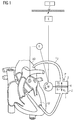
- the pulsation blood pump consists essentially of a bidirectional pumping system, which is connected via a first line L1 and a second line L2 on the one hand to a blood stream, here the aorta AO, and on the other hand to a heart chamber, here the left ventricle LV.
- the bidirectional pumping system consists essentially of a pump P and a pump P driving motor M. As the pump and / or the motor specifically procure in each case and are coupled together, is of minor importance to the invention.
- the motor M and thus the pump P is operated via a controller St according to predetermined heart rhythm alternately in one direction and the other.
- the cardiac rhythm data for controlling the pumping system eg pressure, ECG, contraction, PPS, etc.
- a sensor system S coupled to the controller St and transmitted to the controller St. This is in FIG. 1 merely indicated schematically by a lying in the atrium of the left ventricle LV sensor S, which may be a pressure sensor.
- the energy required for the operation of the pumping system can be made available from an energy store E which, for example, is charged without contact either permanently or preferably temporarily via a transmitter T.
- the piston K is now displaced according to the heart rhythm so that the volume V 1 of the pumping chamber 1 is reduced during systole and accordingly blood from the pumping chamber 1 via the line L 1 is pumped into the left ventricle LV.
- blood from the aorta AO is simultaneously sucked through the line L 2 into the increasing volume V 2 of the second pumping chamber 2.
- the left ventricle LV thereby works against a reduced aortic pressure, and also the blood volume displaced from the pumping chamber 1 flows through the left ventricle LV and the aortic valve into the aorta AO.
- the piston K is moved in the opposite direction, allowing blood from the left ventricle LV is sucked through the line L1 in the pumping chamber 1 and at the same time a corresponding amount of blood from the second pumping chamber 2 is conveyed through the line L2 into the aorta AO.
- the blood pressure in the aorta AO is increased by the blood conveyed into the aorta AO so that the blood flows reliably into the organs, including the heart, and the peripheral bloodstreams.
- the cardiac muscle wall tension can be kept low and blood supply to the heart even more efficient.
- FIG. 2 shows a first modification of this basic principle.
- the piston K is designed here as a differential piston with two piston surfaces of different sizes. Accordingly, the volumes V 1 and V 2 do not change to the same extent during a movement of the piston K in the direction R.
- due to the differential piston K a smaller amount of blood is pumped back and forth between the left ventricle LV and the pumping chamber 1 than between the aorta AO and the second pumping chamber 2.
- the larger piston surface of the differential piston can be either on the side of the heart or the bloodstream.
- the differential piston K requires on the side of the smaller piston surface an additional compliance chamber C, which is connected via a line L 3 to the pump P.
- the compliance chamber C absorbs the difference between the volume displacement V 2 and V 1 , which is positive or negative depending on the direction of displacement of the differential piston K.
- the compliance chamber C is placed in a location within the patient to which it is exposed only to a low ambient pressure, for example in the abdomen, and is over Line L 3 connected to the pump P. In the line L 3 and the compliance chamber C is preferably a liquid, so in particular no blood.
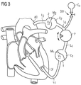
- FIG. 3 shows a second modification of the basic principle.
- the first pumping chamber 1 with a first compliance chamber C 1 forms a first double chamber
- the second pumping chamber 2 forms a second double chamber with a second compliance chamber C 2 .
- the pump chambers 1 and 2 are separated from the compliance chambers C 1 and C 2 in each case by a membrane M 1 and M 2 , so that the volume V 1 and V 2 of the pump chambers 1 and 2 is variable in each case.
- a fluid is then pumped back and forth between the compliance chambers C 1 and C 2 corresponding to the heart rhythm so that the variable volumes V 1 and V 2 of the two pumping chambers 1 and 2 in the previously with respect to FIG. 1 change the way described.
- the pump P is connected via lines L 4 and L 5 to the compliance chambers C 1 and C 2 .
- the lines L 4 , L 5 and the compliance chambers C 1 , C 2 is a hydraulic fluid, so in particular no blood.
- the pump P is thus reliably shielded from the blood circulation by means of the membrane M 1 and M 2 .
- the structure and the effectiveness of the pumps P which can be used for the pump system are thereby favored. Also, while the fatigue strength of the pumping system is significantly improved.
- An additional compliance chamber Cv may be provided to accommodate volume fluctuations when the amounts of blood V 1 and V 2 are different in size.
- FIG. 3 shows such additional compliance chamber Cv for receiving a portion of the funded between the compliance chambers C 1 and C 2 fluid.
- This additional compliance chamber Cv is optional and preferably variably adjustable with respect to its compliance properties.
- the control valve StV serves to set the compliance properties. The adjustment can be done either before or after implantation, preferably, for example, by remote control even after implantation either as needed or constantly. As a result, the blood volumes accommodated in the pumping chambers 1 and 2 can be varied, possibly also dynamically.
- One reason for such a measure may be, for example, that problems arise during the filling of one or the other of the two pumping chambers 1 and 2 or that the available volumes of the pumping chambers 1 and 2 should be deliberately varied.
- the control valve StV By means of the control valve StV, it is thus possible to variably control the intake and discharge volumes of the pumping chambers 1 and 2.
- the volume reduction must not result in so much blood constantly remaining in one of the pumping chambers that successive clumping of the blood is to be feared.
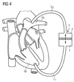
- FIG. 4 finally shows another modification of the in FIG. 1 illustrated basic principle.
- the lines L 1 and L 2 of the pulsation blood pump are not connected to the left ventricle LV and the aorta AO but instead to the right ventricle RV and the pulmonary arteries PA.
Claims (8)
- Pompe à sang à pulsations extra-vasculaire, comprenant
une première conduite (L1) pour la connexion de la pompe à sang à pulsations à un ventricule (LV; RV),
une deuxième conduite (L2) pour la connexion de la pompe à sang à pulsations à un circuit sanguin (AO; PA), et
un système de pompage (P; P , M) bidirectionnel,
caractérisé en ce que le système de pompage bidirectionnel est conçu pour, en alternance, d'une part aspirer du sang par la première conduite (L1) et propulser en même temps du sang par la deuxième conduite (L2), et d'autre part aspirer du sang par la seconde conduite (L2) et propulser en même temps du sang par la première conduite (L1), une commande (St) étant prévue pour actionner le système de pompage (P; P , M), en correspondance avec un rythme cardiaque prédéterminé, en alternance dans l'une et dans l'autre direction (R). - Pompe à sang à pulsations selon la revendication 1, comprenant un ensemble de capteurs (S) couplés à la commande (St) pour la saisie et le transmission de données de rythme cardiaque à la commande (St).
- Pompe à sang à pulsations selon la revendication 1 ou 2, le système de pompage (P; P , M) comportant une première chambre de pompage (1) à volume (V1) variable raccordée à la première conduite (L1), et une deuxième chambre de pompage (2) à volume (V2) variable raccordée à la deuxième conduite (L2), la première et la deuxième chambre de pompage (1, 2) étant couplées de telle manière entre elles que, quand du sang est aspiré par la première conduite (L1) vers la première chambre de pompage (1), du sang de la deuxième chambre de pompage (2) est propulsé dans la deuxième conduite (L2), et inversement.
- Pompe à sang à pulsations selon la revendication 3, la première chambre de pompage (1) formant avec une première chambre de compliance (C1) à volume variable une première chambre double, et la deuxième chambre de pompage (2) formant avec une deuxième chambre de compliance (C2) à volume variable une deuxième chambre double , une paroi de séparation variable (M1, M2) séparant respectivement la première chambre de pompage (1) de la première chambre de compliance (C1) et la deuxième chambre de pompage (2) de la deuxième chambre de compliance (C2), et le système de pompage comprenant une pompe (P) conçue pour véhiculer en va-et-vient un fluide entre la première chambre de compliance (C1) et la deuxième chambre de compliance (C2).
- Pompe à sang à pulsations selon la revendication 4, les parois de séparation (M1, M2) comprenant respectivement une membrane flexible.
- Pompe à sang à pulsations selon une des revendications 4 ou 5, le fluide étant un liquide.
- Pompe à pulsations selon une des revendications de 1 à 6, le système de pompage étant un système de pompage différentiel.
- Pompe à sang à pulsations selon une des revendications de 1 à 7, le système de pompage (P; P , M) étant conçu pour être implanté dans le corps d'un patient.
Applications Claiming Priority (2)
| Application Number | Priority Date | Filing Date | Title |
|---|---|---|---|
| DE102012207042.7A DE102012207042B4 (de) | 2012-04-27 | 2012-04-27 | Pulsationsblutpumpe |
| PCT/EP2013/058648 WO2013160411A1 (fr) | 2012-04-27 | 2013-04-25 | Pompe à sang à pulsations |
Publications (2)
| Publication Number | Publication Date |
|---|---|
| EP2841123A1 EP2841123A1 (fr) | 2015-03-04 |
| EP2841123B1 true EP2841123B1 (fr) | 2016-07-06 |
Family
ID=48227262
Family Applications (1)
| Application Number | Title | Priority Date | Filing Date |
|---|---|---|---|
| EP13719515.2A Active EP2841123B1 (fr) | 2012-04-27 | 2013-04-25 | Pompe à sang à pulsations |
Country Status (7)
| Country | Link |
|---|---|
| US (1) | US9555173B2 (fr) |
| EP (1) | EP2841123B1 (fr) |
| JP (1) | JP6058787B2 (fr) |
| KR (1) | KR101926847B1 (fr) |
| AU (1) | AU2013254650B2 (fr) |
| DE (1) | DE102012207042B4 (fr) |
| WO (1) | WO2013160411A1 (fr) |
Families Citing this family (13)
| Publication number | Priority date | Publication date | Assignee | Title |
|---|---|---|---|---|
| EP4233989A3 (fr) | 2017-06-07 | 2023-10-11 | Shifamed Holdings, LLC | Dispositifs de déplacement de fluide intravasculaire, systèmes et procédés d'utilisation |
| JP7319266B2 (ja) | 2017-11-13 | 2023-08-01 | シファメド・ホールディングス・エルエルシー | 血管内流体移動デバイス、システム、および使用方法 |
| DE102018201030A1 (de) | 2018-01-24 | 2019-07-25 | Kardion Gmbh | Magnetkuppelelement mit magnetischer Lagerungsfunktion |
| CN112004563A (zh) | 2018-02-01 | 2020-11-27 | 施菲姆德控股有限责任公司 | 血管内血泵以及使用和制造方法 |
| EP3536955A1 (fr) * | 2018-03-08 | 2019-09-11 | Berlin Heart GmbH | Dispositif d'entraînement pour une pompe à fluide à membrane et procédé de fonctionnement |
| DE102018211327A1 (de) | 2018-07-10 | 2020-01-16 | Kardion Gmbh | Laufrad für ein implantierbares, vaskuläres Unterstützungssystem |
| JP2022524774A (ja) | 2019-03-08 | 2022-05-10 | サマコア, インコーポレイテッド | 容積形シャトルポンプ心臓およびvad |
| JP2022540616A (ja) | 2019-07-12 | 2022-09-16 | シファメド・ホールディングス・エルエルシー | 血管内血液ポンプならびに製造および使用の方法 |
| WO2021016372A1 (fr) | 2019-07-22 | 2021-01-28 | Shifamed Holdings, Llc | Pompes à sang intravasculaires à entretoises et procédés d'utilisation et de fabrication |
| EP4034192A4 (fr) | 2019-09-25 | 2023-11-29 | Shifamed Holdings, LLC | Dispositifs et systèmes de pompes à sang intravasculaires et leurs procédés d'utilisation et de commande |
| JP2022552579A (ja) | 2019-10-19 | 2022-12-16 | サマコア, インコーポレイテッド | 線形心臓補助拍動性ポンプ |
| DE102020102474A1 (de) | 2020-01-31 | 2021-08-05 | Kardion Gmbh | Pumpe zum Fördern eines Fluids und Verfahren zum Herstellen einer Pumpe |
| CN116549762B (zh) * | 2023-07-10 | 2023-10-31 | 北京悦唯医疗科技有限责任公司 | 左心室辅助装置 |
Family Cites Families (10)
| Publication number | Priority date | Publication date | Assignee | Title |
|---|---|---|---|---|
| US5314469A (en) * | 1992-03-11 | 1994-05-24 | Milwaukee Heart Research Foundation | Artificial heart |
| US20040230090A1 (en) * | 2002-10-07 | 2004-11-18 | Hegde Anant V. | Vascular assist device and methods |
| US7273446B2 (en) | 2003-10-31 | 2007-09-25 | Spence Paul A | Methods, devices and systems for counterpulsation of blood flow to and from the circulatory system |
| WO2007089500A2 (fr) * | 2006-01-30 | 2007-08-09 | Pong-Jeu Lu | Dispositif d'assistance bi-ventriculaire a double pulsation |
| US20100268333A1 (en) * | 2009-04-16 | 2010-10-21 | Gohean Jeffrey R | System and method for controlling pump |
| DE102006035548B4 (de) | 2006-07-27 | 2009-02-12 | Deutsches Zentrum für Luft- und Raumfahrt e.V. | Kunstherz |
| JP5250755B2 (ja) * | 2008-03-25 | 2013-07-31 | 株式会社サンメディカル技術研究所 | 補助人工心臓ポンプ駆動装置及び補助人工心臓システム |
| ATE556729T1 (de) * | 2008-08-05 | 2012-05-15 | Michigan Critical Care Consultants Inc | Gerät und verfahren zur überwachung und kontrolle des extrakorporalen blutflusses relativ zum flüssigkeitsstatus eines patienten |
| DE102010018233A1 (de) * | 2010-04-23 | 2011-10-27 | Deutsches Zentrum für Luft- und Raumfahrt e.V. | Herzunterstützungsvorrichtung |
| EP2388028A1 (fr) * | 2010-05-20 | 2011-11-23 | Berlin Heart GmbH | Procédé destiné au fonctionnement d'un système de pompe |
-
2012
- 2012-04-27 DE DE102012207042.7A patent/DE102012207042B4/de active Active
-
2013
- 2013-04-25 JP JP2015507539A patent/JP6058787B2/ja active Active
- 2013-04-25 KR KR1020147032328A patent/KR101926847B1/ko active IP Right Grant
- 2013-04-25 WO PCT/EP2013/058648 patent/WO2013160411A1/fr active Application Filing
- 2013-04-25 US US14/396,718 patent/US9555173B2/en active Active
- 2013-04-25 AU AU2013254650A patent/AU2013254650B2/en active Active
- 2013-04-25 EP EP13719515.2A patent/EP2841123B1/fr active Active
Also Published As
| Publication number | Publication date |
|---|---|
| JP2015514530A (ja) | 2015-05-21 |
| DE102012207042A1 (de) | 2013-10-31 |
| AU2013254650B2 (en) | 2016-12-22 |
| KR101926847B1 (ko) | 2018-12-07 |
| JP6058787B2 (ja) | 2017-01-11 |
| WO2013160411A1 (fr) | 2013-10-31 |
| AU2013254650A1 (en) | 2014-11-13 |
| EP2841123A1 (fr) | 2015-03-04 |
| KR20150008135A (ko) | 2015-01-21 |
| US9555173B2 (en) | 2017-01-31 |
| US20150133722A1 (en) | 2015-05-14 |
| DE102012207042B4 (de) | 2017-09-07 |
Similar Documents
| Publication | Publication Date | Title |
|---|---|---|
| EP2841123B1 (fr) | Pompe à sang à pulsations | |
| EP3010562B1 (fr) | Système d'assistance cardiaque | |
| EP2134385B1 (fr) | Dispositif d'assistance cardiaque et circulatoire | |
| DE3923836C1 (fr) | ||
| DE2707951A1 (de) | Vorrichtung zur versorgung eines patienten mit einem pulsierenden blutfluss | |
| DE10119691A1 (de) | System zum Unterstützen des linken Herzventrikels | |
| EP2523702B1 (fr) | Agencement comportant une pompe à sang et un échangeur gazeux pour l'oxygénation de membrane extracorporelle | |
| DE102009051805A1 (de) | Dialysevorrichtungen mit Piezopumpen | |
| WO2019158420A9 (fr) | Cathéter de pompe pour la conduite pulsatile dirigée du sang | |
| WO2021170561A1 (fr) | Pompe à membrane médicale et système de pompe à membrane | |
| WO2016119771A2 (fr) | Agencement comportant une conduite d'aspiration, une conduite de refoulement et une pompe | |
| DE102008038243B4 (de) | LVAD-Pumpenanordnung, und Verfahren zum Betreiben einer solchen | |
| DE102017103350A1 (de) | Herzfunktionssystem mit einer Kunstherzvorrichtung mit redundanten Blut-Strömungspfaden sowie Verfahren zum Unterstützen der Herzfunktion und Verwendung | |
| EP3634525B1 (fr) | Dispositif d'assistance ventriculaire | |
| DE3234572A1 (de) | Pumpvorrichtung fuer die implantation in einen menschlichen oder tierischen koerper | |
| DE202007019486U1 (de) | Vorrichtung zur Unterstützung des Herzens und des Kreislaufs | |
| DE2558921A1 (de) | Antrieb fuer eine pneumatische oder hydraulische pulspumpe | |
| Körfer et al. | Assistierte Zirkulation | |
| Körfer et al. | 5.3 Assistierte Zirkulation | |
| EP2944338A1 (fr) | Implant cardiovasculaire autonome doté d'un clapet anti-retour | |
| Boeken et al. | Langzeitunterstützung | |
| DE20307003U1 (de) | Kunstherzanordnung |
Legal Events
| Date | Code | Title | Description |
|---|---|---|---|
| PUAI | Public reference made under article 153(3) epc to a published international application that has entered the european phase |
Free format text: ORIGINAL CODE: 0009012 |
|
| 17P | Request for examination filed |
Effective date: 20141023 |
|
| AK | Designated contracting states |
Kind code of ref document: A1 Designated state(s): AL AT BE BG CH CY CZ DE DK EE ES FI FR GB GR HR HU IE IS IT LI LT LU LV MC MK MT NL NO PL PT RO RS SE SI SK SM TR |
|
| AX | Request for extension of the european patent |
Extension state: BA ME |
|
| DAX | Request for extension of the european patent (deleted) | ||
| GRAP | Despatch of communication of intention to grant a patent |
Free format text: ORIGINAL CODE: EPIDOSNIGR1 |
|
| INTG | Intention to grant announced |
Effective date: 20160114 |
|
| GRAS | Grant fee paid |
Free format text: ORIGINAL CODE: EPIDOSNIGR3 |
|
| GRAA | (expected) grant |
Free format text: ORIGINAL CODE: 0009210 |
|
| AK | Designated contracting states |
Kind code of ref document: B1 Designated state(s): AL AT BE BG CH CY CZ DE DK EE ES FI FR GB GR HR HU IE IS IT LI LT LU LV MC MK MT NL NO PL PT RO RS SE SI SK SM TR |
|
| REG | Reference to a national code |
Ref country code: GB Ref legal event code: FG4D Free format text: NOT ENGLISH |
|
| REG | Reference to a national code |
Ref country code: AT Ref legal event code: REF Ref document number: 810239 Country of ref document: AT Kind code of ref document: T Effective date: 20160715 Ref country code: CH Ref legal event code: EP |
|
| REG | Reference to a national code |
Ref country code: IE Ref legal event code: FG4D Free format text: LANGUAGE OF EP DOCUMENT: GERMAN |
|
| REG | Reference to a national code |
Ref country code: DE Ref legal event code: R096 Ref document number: 502013003617 Country of ref document: DE |
|
| REG | Reference to a national code |
Ref country code: NL Ref legal event code: FP |
|
| REG | Reference to a national code |
Ref country code: LT Ref legal event code: MG4D |
|
| PG25 | Lapsed in a contracting state [announced via postgrant information from national office to epo] |
Ref country code: RS Free format text: LAPSE BECAUSE OF FAILURE TO SUBMIT A TRANSLATION OF THE DESCRIPTION OR TO PAY THE FEE WITHIN THE PRESCRIBED TIME-LIMIT Effective date: 20160706 Ref country code: FI Free format text: LAPSE BECAUSE OF FAILURE TO SUBMIT A TRANSLATION OF THE DESCRIPTION OR TO PAY THE FEE WITHIN THE PRESCRIBED TIME-LIMIT Effective date: 20160706 Ref country code: NO Free format text: LAPSE BECAUSE OF FAILURE TO SUBMIT A TRANSLATION OF THE DESCRIPTION OR TO PAY THE FEE WITHIN THE PRESCRIBED TIME-LIMIT Effective date: 20161006 Ref country code: IT Free format text: LAPSE BECAUSE OF FAILURE TO SUBMIT A TRANSLATION OF THE DESCRIPTION OR TO PAY THE FEE WITHIN THE PRESCRIBED TIME-LIMIT Effective date: 20160706 Ref country code: LT Free format text: LAPSE BECAUSE OF FAILURE TO SUBMIT A TRANSLATION OF THE DESCRIPTION OR TO PAY THE FEE WITHIN THE PRESCRIBED TIME-LIMIT Effective date: 20160706 Ref country code: IS Free format text: LAPSE BECAUSE OF FAILURE TO SUBMIT A TRANSLATION OF THE DESCRIPTION OR TO PAY THE FEE WITHIN THE PRESCRIBED TIME-LIMIT Effective date: 20161106 Ref country code: HR Free format text: LAPSE BECAUSE OF FAILURE TO SUBMIT A TRANSLATION OF THE DESCRIPTION OR TO PAY THE FEE WITHIN THE PRESCRIBED TIME-LIMIT Effective date: 20160706 |
|
| PG25 | Lapsed in a contracting state [announced via postgrant information from national office to epo] |
Ref country code: ES Free format text: LAPSE BECAUSE OF FAILURE TO SUBMIT A TRANSLATION OF THE DESCRIPTION OR TO PAY THE FEE WITHIN THE PRESCRIBED TIME-LIMIT Effective date: 20160706 Ref country code: LV Free format text: LAPSE BECAUSE OF FAILURE TO SUBMIT A TRANSLATION OF THE DESCRIPTION OR TO PAY THE FEE WITHIN THE PRESCRIBED TIME-LIMIT Effective date: 20160706 Ref country code: GR Free format text: LAPSE BECAUSE OF FAILURE TO SUBMIT A TRANSLATION OF THE DESCRIPTION OR TO PAY THE FEE WITHIN THE PRESCRIBED TIME-LIMIT Effective date: 20161007 Ref country code: SE Free format text: LAPSE BECAUSE OF FAILURE TO SUBMIT A TRANSLATION OF THE DESCRIPTION OR TO PAY THE FEE WITHIN THE PRESCRIBED TIME-LIMIT Effective date: 20160706 Ref country code: PL Free format text: LAPSE BECAUSE OF FAILURE TO SUBMIT A TRANSLATION OF THE DESCRIPTION OR TO PAY THE FEE WITHIN THE PRESCRIBED TIME-LIMIT Effective date: 20160706 Ref country code: PT Free format text: LAPSE BECAUSE OF FAILURE TO SUBMIT A TRANSLATION OF THE DESCRIPTION OR TO PAY THE FEE WITHIN THE PRESCRIBED TIME-LIMIT Effective date: 20161107 |
|
| REG | Reference to a national code |
Ref country code: DE Ref legal event code: R097 Ref document number: 502013003617 Country of ref document: DE |
|
| REG | Reference to a national code |
Ref country code: FR Ref legal event code: PLFP Year of fee payment: 5 |
|
| PG25 | Lapsed in a contracting state [announced via postgrant information from national office to epo] |
Ref country code: EE Free format text: LAPSE BECAUSE OF FAILURE TO SUBMIT A TRANSLATION OF THE DESCRIPTION OR TO PAY THE FEE WITHIN THE PRESCRIBED TIME-LIMIT Effective date: 20160706 Ref country code: RO Free format text: LAPSE BECAUSE OF FAILURE TO SUBMIT A TRANSLATION OF THE DESCRIPTION OR TO PAY THE FEE WITHIN THE PRESCRIBED TIME-LIMIT Effective date: 20160706 |
|
| PLBE | No opposition filed within time limit |
Free format text: ORIGINAL CODE: 0009261 |
|
| STAA | Information on the status of an ep patent application or granted ep patent |
Free format text: STATUS: NO OPPOSITION FILED WITHIN TIME LIMIT |
|
| PG25 | Lapsed in a contracting state [announced via postgrant information from national office to epo] |
Ref country code: SM Free format text: LAPSE BECAUSE OF FAILURE TO SUBMIT A TRANSLATION OF THE DESCRIPTION OR TO PAY THE FEE WITHIN THE PRESCRIBED TIME-LIMIT Effective date: 20160706 Ref country code: SK Free format text: LAPSE BECAUSE OF FAILURE TO SUBMIT A TRANSLATION OF THE DESCRIPTION OR TO PAY THE FEE WITHIN THE PRESCRIBED TIME-LIMIT Effective date: 20160706 Ref country code: CZ Free format text: LAPSE BECAUSE OF FAILURE TO SUBMIT A TRANSLATION OF THE DESCRIPTION OR TO PAY THE FEE WITHIN THE PRESCRIBED TIME-LIMIT Effective date: 20160706 Ref country code: BG Free format text: LAPSE BECAUSE OF FAILURE TO SUBMIT A TRANSLATION OF THE DESCRIPTION OR TO PAY THE FEE WITHIN THE PRESCRIBED TIME-LIMIT Effective date: 20161006 Ref country code: DK Free format text: LAPSE BECAUSE OF FAILURE TO SUBMIT A TRANSLATION OF THE DESCRIPTION OR TO PAY THE FEE WITHIN THE PRESCRIBED TIME-LIMIT Effective date: 20160706 |
|
| 26N | No opposition filed |
Effective date: 20170407 |
|
| REG | Reference to a national code |
Ref country code: DE Ref legal event code: R082 Ref document number: 502013003617 Country of ref document: DE Representative=s name: KLUNKER IP PATENTANWAELTE PARTG MBB, DE |
|
| PG25 | Lapsed in a contracting state [announced via postgrant information from national office to epo] |
Ref country code: SI Free format text: LAPSE BECAUSE OF FAILURE TO SUBMIT A TRANSLATION OF THE DESCRIPTION OR TO PAY THE FEE WITHIN THE PRESCRIBED TIME-LIMIT Effective date: 20160706 |
|
| REG | Reference to a national code |
Ref country code: CH Ref legal event code: PL |
|
| REG | Reference to a national code |
Ref country code: IE Ref legal event code: MM4A |
|
| PG25 | Lapsed in a contracting state [announced via postgrant information from national office to epo] |
Ref country code: MC Free format text: LAPSE BECAUSE OF FAILURE TO SUBMIT A TRANSLATION OF THE DESCRIPTION OR TO PAY THE FEE WITHIN THE PRESCRIBED TIME-LIMIT Effective date: 20160706 |
|
| PG25 | Lapsed in a contracting state [announced via postgrant information from national office to epo] |
Ref country code: LI Free format text: LAPSE BECAUSE OF NON-PAYMENT OF DUE FEES Effective date: 20170430 Ref country code: LU Free format text: LAPSE BECAUSE OF NON-PAYMENT OF DUE FEES Effective date: 20170425 Ref country code: CH Free format text: LAPSE BECAUSE OF NON-PAYMENT OF DUE FEES Effective date: 20170430 |
|
| REG | Reference to a national code |
Ref country code: BE Ref legal event code: MM Effective date: 20170430 |
|
| REG | Reference to a national code |
Ref country code: FR Ref legal event code: PLFP Year of fee payment: 6 |
|
| PG25 | Lapsed in a contracting state [announced via postgrant information from national office to epo] |
Ref country code: IE Free format text: LAPSE BECAUSE OF NON-PAYMENT OF DUE FEES Effective date: 20170425 |
|
| PG25 | Lapsed in a contracting state [announced via postgrant information from national office to epo] |
Ref country code: BE Free format text: LAPSE BECAUSE OF NON-PAYMENT OF DUE FEES Effective date: 20170430 |
|
| PG25 | Lapsed in a contracting state [announced via postgrant information from national office to epo] |
Ref country code: MT Free format text: LAPSE BECAUSE OF FAILURE TO SUBMIT A TRANSLATION OF THE DESCRIPTION OR TO PAY THE FEE WITHIN THE PRESCRIBED TIME-LIMIT Effective date: 20160706 |
|
| PG25 | Lapsed in a contracting state [announced via postgrant information from national office to epo] |
Ref country code: AL Free format text: LAPSE BECAUSE OF FAILURE TO SUBMIT A TRANSLATION OF THE DESCRIPTION OR TO PAY THE FEE WITHIN THE PRESCRIBED TIME-LIMIT Effective date: 20160706 |
|
| REG | Reference to a national code |
Ref country code: AT Ref legal event code: MM01 Ref document number: 810239 Country of ref document: AT Kind code of ref document: T Effective date: 20180425 |
|
| PG25 | Lapsed in a contracting state [announced via postgrant information from national office to epo] |
Ref country code: HU Free format text: LAPSE BECAUSE OF FAILURE TO SUBMIT A TRANSLATION OF THE DESCRIPTION OR TO PAY THE FEE WITHIN THE PRESCRIBED TIME-LIMIT; INVALID AB INITIO Effective date: 20130425 |
|
| PG25 | Lapsed in a contracting state [announced via postgrant information from national office to epo] |
Ref country code: AT Free format text: LAPSE BECAUSE OF NON-PAYMENT OF DUE FEES Effective date: 20180425 Ref country code: CY Free format text: LAPSE BECAUSE OF FAILURE TO SUBMIT A TRANSLATION OF THE DESCRIPTION OR TO PAY THE FEE WITHIN THE PRESCRIBED TIME-LIMIT Effective date: 20160706 |
|
| PG25 | Lapsed in a contracting state [announced via postgrant information from national office to epo] |
Ref country code: MK Free format text: LAPSE BECAUSE OF FAILURE TO SUBMIT A TRANSLATION OF THE DESCRIPTION OR TO PAY THE FEE WITHIN THE PRESCRIBED TIME-LIMIT Effective date: 20160706 |
|
| PG25 | Lapsed in a contracting state [announced via postgrant information from national office to epo] |
Ref country code: TR Free format text: LAPSE BECAUSE OF FAILURE TO SUBMIT A TRANSLATION OF THE DESCRIPTION OR TO PAY THE FEE WITHIN THE PRESCRIBED TIME-LIMIT Effective date: 20160706 |
|
| REG | Reference to a national code |
Ref country code: DE Ref legal event code: R079 Ref document number: 502013003617 Country of ref document: DE Free format text: PREVIOUS MAIN CLASS: A61M0001100000 Ipc: A61M0060000000 |
|
| PGFP | Annual fee paid to national office [announced via postgrant information from national office to epo] |
Ref country code: FR Payment date: 20230321 Year of fee payment: 11 |
|
| P01 | Opt-out of the competence of the unified patent court (upc) registered |
Effective date: 20230522 |
|
| PGFP | Annual fee paid to national office [announced via postgrant information from national office to epo] |
Ref country code: DE Payment date: 20230321 Year of fee payment: 11 |
|
| PGFP | Annual fee paid to national office [announced via postgrant information from national office to epo] |
Ref country code: NL Payment date: 20240320 Year of fee payment: 12 |
|
| PGFP | Annual fee paid to national office [announced via postgrant information from national office to epo] |
Ref country code: GB Payment date: 20240320 Year of fee payment: 12 |