EP2840887B1 - Method, control, message receipt module, data message format and network protocol for farm system - Google Patents
Method, control, message receipt module, data message format and network protocol for farm system Download PDFInfo
- Publication number
- EP2840887B1 EP2840887B1 EP13737439.3A EP13737439A EP2840887B1 EP 2840887 B1 EP2840887 B1 EP 2840887B1 EP 13737439 A EP13737439 A EP 13737439A EP 2840887 B1 EP2840887 B1 EP 2840887B1
- Authority
- EP
- European Patent Office
- Prior art keywords
- devices
- network
- message
- relating
- field
- Prior art date
- Legal status (The legal status is an assumption and is not a legal conclusion. Google has not performed a legal analysis and makes no representation as to the accuracy of the status listed.)
- Active
Links
Images


Classifications
-
- A—HUMAN NECESSITIES
- A01—AGRICULTURE; FORESTRY; ANIMAL HUSBANDRY; HUNTING; TRAPPING; FISHING
- A01J—MANUFACTURE OF DAIRY PRODUCTS
- A01J5/00—Milking machines or devices
- A01J5/007—Monitoring milking processes; Control or regulation of milking machines
-
- A—HUMAN NECESSITIES
- A01—AGRICULTURE; FORESTRY; ANIMAL HUSBANDRY; HUNTING; TRAPPING; FISHING
- A01K—ANIMAL HUSBANDRY; AVICULTURE; APICULTURE; PISCICULTURE; FISHING; REARING OR BREEDING ANIMALS, NOT OTHERWISE PROVIDED FOR; NEW BREEDS OF ANIMALS
- A01K1/00—Housing animals; Equipment therefor
- A01K1/12—Milking stations
-
- G—PHYSICS
- G05—CONTROLLING; REGULATING
- G05B—CONTROL OR REGULATING SYSTEMS IN GENERAL; FUNCTIONAL ELEMENTS OF SUCH SYSTEMS; MONITORING OR TESTING ARRANGEMENTS FOR SUCH SYSTEMS OR ELEMENTS
- G05B15/00—Systems controlled by a computer
- G05B15/02—Systems controlled by a computer electric
-
- H—ELECTRICITY
- H04—ELECTRIC COMMUNICATION TECHNIQUE
- H04L—TRANSMISSION OF DIGITAL INFORMATION, e.g. TELEGRAPHIC COMMUNICATION
- H04L61/00—Network arrangements, protocols or services for addressing or naming
- H04L61/35—Network arrangements, protocols or services for addressing or naming involving non-standard use of addresses for implementing network functionalities, e.g. coding subscription information within the address or functional addressing, i.e. assigning an address to a function
-
- H—ELECTRICITY
- H04—ELECTRIC COMMUNICATION TECHNIQUE
- H04L—TRANSMISSION OF DIGITAL INFORMATION, e.g. TELEGRAPHIC COMMUNICATION
- H04L61/00—Network arrangements, protocols or services for addressing or naming
- H04L61/50—Address allocation
- H04L61/5038—Address allocation for local use, e.g. in LAN or USB networks, or in a controller area network [CAN]
-
- H—ELECTRICITY
- H04—ELECTRIC COMMUNICATION TECHNIQUE
- H04L—TRANSMISSION OF DIGITAL INFORMATION, e.g. TELEGRAPHIC COMMUNICATION
- H04L67/00—Network arrangements or protocols for supporting network services or applications
- H04L67/01—Protocols
- H04L67/12—Protocols specially adapted for proprietary or special-purpose networking environments, e.g. medical networks, sensor networks, networks in vehicles or remote metering networks
-
- H—ELECTRICITY
- H04—ELECTRIC COMMUNICATION TECHNIQUE
- H04L—TRANSMISSION OF DIGITAL INFORMATION, e.g. TELEGRAPHIC COMMUNICATION
- H04L2101/00—Indexing scheme associated with group H04L61/00
- H04L2101/60—Types of network addresses
- H04L2101/604—Address structures or formats
Definitions
- the present invention relates to a method for controlling devices within an agricultural network system via a network bus, such as a physical network bus or a logical network bus, wherein the devices are controlled by means of control information which is transmitted to the devices by means of messages comprising a content and a header title.
- the present invention also relates to a control device and/or a control server.
- the present invention also relates to a message reception module, preferably for arrangement in a functional device.
- the present invention also relates to a data message format.
- the present invention also relates to a network protocol.
- WO2007071406 discloses a dairy farm system comprises a plurality of apparatuses for performing actions related to the operation of the dairy farm system, wherein the apparatuses are connected in a network, and at least one of the apparatuses is movable.
- the movable apparatus is wirelessly connectable to the network via a short-range radio link, preferably a Bluetooth link.
- US2004083293 discloses in a massively parallel system, a method and apparatus for uniquely assigning a MAC address to a device encodes the MAC address with a physical location of the device.
- the method and apparatus include configuring device interconnections of the parallel system with physical topological information such as a rack number, a midplane number, a card number, and a chip number.
- WO2005003882 discloses a method of handling packets in a network.
- the Method includes receiving a packet including an IEEE MAC address field, which carries a MAC address of a network element, examining at least one sub-portion of the IEEE MAC address field, which sub-portion represents a set of elements to which the network element belongs within the network, but does not allow unique identification of the network element in the network and handling the packet responsive to the at least one examined sub-portion.
- US7889051 discloses a location-Based Addressing (LBA) as a method of controlling and commissioning networked lighting devices.
- the lighting devices communicate over a wireless network using radio frequency communication protocols.
- the lighting devices are commissioned or grouped based on their respective locations in a building floor plan or a building architecture.
- the lighting devices are commissioned to respond to radio frequency communications that correspond to their respective locations.
- WO02097555 discloses a network control system for home appliances that satisfies the characteristics of low-cost and high-efficiency with respect to currently used appliances adopting a low-performance microcomputer.
- the system is constructed to define a master/slave type communication structure with respect to the respective appliances; construct a network by connecting the appliances through the serial communication function; and enable the appliances to communicate with one another if a predetermined communication event is produced.
- US2009248896 discloses techniques for managing communications between multiple computing nodes, such as computing nodes that are separated by one or more physical networks.
- the techniques may be used to provide a virtual network between multiple computing nodes that are separated by one or more intermediate physical networks, such as from the edge of the one or more intermediate physical networks by modifying communications that enter and/or leave the intermediate physical networks.
- RAAB A "CAN - CONTROLLER AREA NETWORK", ELEKTOR, CANTERBURY, GB, (19920901), vol. 18, no. 203, ISSN 0268-4519, pages 56 - 59 discloses distributed real-time control with very high noise immunity.
- CAN allows flexible network configurations based on different types of microprocessor and microcontroller. CANs are typically found in the automotive and industrial environment.
- the present invention provides for this purpose a method for controlling devices according to claim 1.
- the present invention provides the advantage that the milking process can be optimized for this specific animal.
- a further advantage of a method according to the present invention is that groups of devices can be controlled directly by means of standard messages, wherein the header title provides for the specific addressing. It hereby becomes possible for instance for individual milk pulsators of different installations to be controlled separately, but also for all to be controlled with one addressing on the basis of the device type. All milk pulsators of each station can for instance thus be controlled with one message.
- the status of all devices can also be retrieved, on the basis of which a central control can receive data from all stations or devices.
- the status thereof can be continuously tracked, on the basis of which other systems in the milking system can be controlled in optimal manner.
- the present invention can also be applied to all manner of types of device applied within an agricultural system, such as for manure processing, feeder systems, systems for controlling the temperature in living areas, systems for cooling products such as cooling tanks, access systems such as gates, identification systems and so on.
- a subset according to the present invention represents a cross-section of the total number of devices, wherein each device is a network node.
- the network is hereby divided physically, by means of a message reception module such as a network card, or logically into a number of sets. Examples hereof are sets such as functions, locations, groups, device type or parts of the network.
- a first type of data field a type field, relates to a type of device connected to the network bus, which type can have an overlap with networks, functions, locations or groups.
- An instruction message can be transmitted by means of such a field to one or all of these devices.
- An instruction message can be transmitted by means of such a field to one or all of these devices.
- the stated preferred embodiments specify possible combinations for compiling a header title comprising identification information for identifying a precisely defined subset of the devices connected to the network bus. Status information of such devices can hereby be retrieved, whereby accurate information can be collected about any realizable combination of devices.
- control of the devices can be optimized to considerable extent on the basis of predetermined programs, but can also be influenced by such status information. It is hereby possible to achieve that the yields of the agricultural processes are optimized, and that the costs of performing the agricultural processes are minimized, and that these are adapted to each other for the purpose of optimizing the overall process.
- a data field is more preferably suitable for identifying 256 devices, such as by means of two hexadecimal characters. If a greater number of devices have to be identified, a greater number of information bits can be applied within the context of the present invention.
- the header title can here more preferably comprise a message type identifier.
- a value of any said data field is a broadcast value for designating each device which complies with this data field.
- the value 00 is applied for this purpose in the examples.
- a further aspect according to the present invention relates to a control device according to claim 5.
- control device can be a server or a workstation or any other computer provided with software for executing the method.
- a further aspect according to the present invention relates to a message reception module according to claim 6.
- a further aspect according to the present invention relates to a device according to claim 7.
- a further aspect according to the present invention relates to a system according to claim 8.
- a further aspect according to the present invention relates to a data message according to claim 9.
- a first preferred embodiment according to the present invention relates to a farm management system 1.
- the backbone of the system is the network bus 2 for linking the systems. Coupled to the bus 2 are workstations or servers 3 with which the devices in the lower part of the figure can be controlled.
- Each device for controlling comprises a network card 17 which is configured to receive or reject messages in correct manner in accordance with a method and protocol according to the present invention.
- Cooled storage tanks 11, 12 are coupled to computers 3 by means of network bus 2.
- a control 13 for a gate, a weighing system 14 for weighing products or animals, an identification system 15 and milk meters 16 for measuring the mass of milk are further coupled to the bus.
- Each of these devices has to be controlled and be able to send information back to the computers.
- the message comprises a header title 21 and a DLC field, in addition to data fields 23 for content of the message.
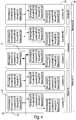
- Header title 21 comprises a message indicator 30, a field 35' for designating the type 35 of device for which the message is intended, a function field 34' for designating the function 34 of the device for which the message is intended, a location field 33' for designating the location 33 of the device for which the message is intended, a group field 31' for designating the group 31 of the device for which the message is intended and a network field 32' for designating the network 32 for which the message is intended.
- the 29 bits identifier can be divided in groupwise manner into areas for identifying locations or functions, in this case for instance the 3 bits message identifier, 7 bits device type 35', which in addition to designating the type of device can also designate a type of function, a 4 bits index number 34' for designating a function or subfunction, the 8 bits location identifier 33', the 4 bits group identifier 31' and/or the 3 bits network identifier 32'.
- Fig. 3 Shown in schematic manner in Fig. 3 is an addressing of a message intended for a specific device.
- the addressing is as follows.
- Shown in schematic manner in figure 4 is an addressing of a message addressed to all devices at a location. As stated above, a broadcast is indicated by means of the designation 0 0. The addressing is as follows.
- FIG. 5 Shown in schematic manner in Fig. 5 is an addressing of a message addressed to all devices of the type B with a network identifier 02.
- the addressing is as follows.
- Fig. 6 Shown in schematic manner in Fig. 6 is an addressing of a message addressed to all devices of the type network 2.
- the addressing is as follows.
- Fig. 7 Shown in schematic manner in Fig. 7 is an addressing of a message addressed to all devices with a function designation 0 2.
- the addressing is as follows.
- a control valve has two coils which can be actuated independently of each other in order to open or close a vacuum channel.
- the electronics built into the CV provide for the actuation of these coils.
- a CV can be used for many applications, several possibilities following below:
- the CV according to the present invention is equipped with means for receiving and interpreting messages encoded according to the present invention. These means are programmable so as to be suitable for executing such functions.
- pulse sequences are for instance programmable, after which the desired pulse sequence is selectable by means of the messages according to the present invention for the purpose of performing the milking, for instance by means of a predetermined entry in the field 35' or the field 34'. Use can therefore be made here of sequences specifically tailored to a specific animal.
Landscapes
- Life Sciences & Earth Sciences (AREA)
- Engineering & Computer Science (AREA)
- Environmental Sciences (AREA)
- Computer Networks & Wireless Communication (AREA)
- Signal Processing (AREA)
- Animal Husbandry (AREA)
- Zoology (AREA)
- Biodiversity & Conservation Biology (AREA)
- General Physics & Mathematics (AREA)
- Physics & Mathematics (AREA)
- General Engineering & Computer Science (AREA)
- Automation & Control Theory (AREA)
- Health & Medical Sciences (AREA)
- Computing Systems (AREA)
- General Health & Medical Sciences (AREA)
- Medical Informatics (AREA)
- Small-Scale Networks (AREA)
- Management, Administration, Business Operations System, And Electronic Commerce (AREA)
- Control By Computers (AREA)
- Computer And Data Communications (AREA)
- Selective Calling Equipment (AREA)
Description
- The present invention relates to a method for controlling devices within an agricultural network system via a network bus, such as a physical network bus or a logical network bus, wherein the devices are controlled by means of control information which is transmitted to the devices by means of messages comprising a content and a header title. The present invention also relates to a control device and/or a control server. The present invention also relates to a message reception module, preferably for arrangement in a functional device. The present invention also relates to a data message format. The present invention also relates to a network protocol.
- It is known to link a number of devices on a farm to a central server by means of a network. In a rudimentary sense it is hereby possible for instance to exchange data between a milking machine and a server. Such a system has the advantage that such data become available electronically at the server. For efficient operational management it is however increasingly important that processes, such as for instance milking, can be monitored such that control can hereby be optimized.
-
WO2007071406 discloses a dairy farm system comprises a plurality of apparatuses for performing actions related to the operation of the dairy farm system, wherein the apparatuses are connected in a network, and at least one of the apparatuses is movable. The movable apparatus is wirelessly connectable to the network via a short-range radio link, preferably a Bluetooth link. -
US2004083293 discloses in a massively parallel system, a method and apparatus for uniquely assigning a MAC address to a device encodes the MAC address with a physical location of the device. The method and apparatus include configuring device interconnections of the parallel system with physical topological information such as a rack number, a midplane number, a card number, and a chip number. -
WO2005003882 discloses a method of handling packets in a network. The Method includes receiving a packet including an IEEE MAC address field, which carries a MAC address of a network element, examining at least one sub-portion of the IEEE MAC address field, which sub-portion represents a set of elements to which the network element belongs within the network, but does not allow unique identification of the network element in the network and handling the packet responsive to the at least one examined sub-portion. -
US7889051 discloses a location-Based Addressing (LBA) as a method of controlling and commissioning networked lighting devices. The lighting devices communicate over a wireless network using radio frequency communication protocols. The lighting devices are commissioned or grouped based on their respective locations in a building floor plan or a building architecture. The lighting devices are commissioned to respond to radio frequency communications that correspond to their respective locations. -
WO02097555 -
US2009248896 discloses techniques for managing communications between multiple computing nodes, such as computing nodes that are separated by one or more physical networks. In some situations, the techniques may be used to provide a virtual network between multiple computing nodes that are separated by one or more intermediate physical networks, such as from the edge of the one or more intermediate physical networks by modifying communications that enter and/or leave the intermediate physical networks. - RAAB A, "CAN - CONTROLLER AREA NETWORK", ELEKTOR, CANTERBURY, GB, (19920901), vol. 18, no. 203, ISSN 0268-4519, pages 56 - 59 discloses distributed real-time control with very high noise immunity. CAN allows flexible network configurations based on different types of microprocessor and microcontroller. CANs are typically found in the automotive and industrial environment.
- ZELTWANGER H, "CAN-CHIPS - DIE GROSSE VIELFALT. VOR- UND NACHTEILE DER ANGEBOTENEN CAN-CONTROLLER", ELEKTRONIK, IRL PRESS LIMITED, DE, (19940419), vol. 43, no. 8, ISSN 0013-5658, pages 68,70 - 73 discloses an overview of can chips commercially available for performing can communications according to can 2.0 A en 2.0 B.
- "Communication Technology is the Backbone of Precision Agriculture", A. Munack et. al., Agricultural Engineering International: the CIGR Journal of Scientific Research and Development discloses developments from various influences from environment into agriculture and vice versa networking requirements of precision agriculture are explained. At the level of data exchange between agricultural and non agricultural institutions global networks such as the Internet are used and data contents are defined by non agricultural suppliers or customers. Main characteristics of these networks are presented.
- The present invention provides for this purpose a method for controlling devices according to
claim 1. - If for instance a dairy cow is transferred from one group to another group, the present invention provides the advantage that the milking process can be optimized for this specific animal.
- A further advantage of a method according to the present invention is that groups of devices can be controlled directly by means of standard messages, wherein the header title provides for the specific addressing. It hereby becomes possible for instance for individual milk pulsators of different installations to be controlled separately, but also for all to be controlled with one addressing on the basis of the device type. All milk pulsators of each station can for instance thus be controlled with one message.
- Conversely, the status of all devices can also be retrieved, on the basis of which a central control can receive data from all stations or devices.
- For instance in the case a mass meter for the milk extracted from a cow is applied, the status thereof can be continuously tracked, on the basis of which other systems in the milking system can be controlled in optimal manner.
- In addition to the stated example of a milking system, the present invention can also be applied to all manner of types of device applied within an agricultural system, such as for manure processing, feeder systems, systems for controlling the temperature in living areas, systems for cooling products such as cooling tanks, access systems such as gates, identification systems and so on.
- A subset according to the present invention represents a cross-section of the total number of devices, wherein each device is a network node. The network is hereby divided physically, by means of a message reception module such as a network card, or logically into a number of sets. Examples hereof are sets such as functions, locations, groups, device type or parts of the network. In a first preferred embodiment a first type of data field, a type field, relates to a type of device connected to the network bus, which type can have an overlap with networks, functions, locations or groups. An instruction message can be transmitted by means of such a field to one or all of these devices.
- An instruction message can be transmitted by means of such a field to one or all of these devices.
- In combination the stated preferred embodiments specify possible combinations for compiling a header title comprising identification information for identifying a precisely defined subset of the devices connected to the network bus. Status information of such devices can hereby be retrieved, whereby accurate information can be collected about any realizable combination of devices.
- The control of the devices can be optimized to considerable extent on the basis of predetermined programs, but can also be influenced by such status information. It is hereby possible to achieve that the yields of the agricultural processes are optimized, and that the costs of performing the agricultural processes are minimized, and that these are adapted to each other for the purpose of optimizing the overall process.
- In a further preferred embodiment a data field is more preferably suitable for identifying 256 devices, such as by means of two hexadecimal characters. If a greater number of devices have to be identified, a greater number of information bits can be applied within the context of the present invention. The header title can here more preferably comprise a message type identifier.
- In a further preferred embodiment a value of any said data field is a broadcast value for designating each device which complies with this data field. The value 00 is applied for this purpose in the examples.
- A further aspect according to the present invention relates to a control device according to claim 5.
- the method are achieved by means of such a control device. Such a control device can be a server or a workstation or any other computer provided with software for executing the method.
- A further aspect according to the present invention relates to a message reception module according to claim 6.
- A further aspect according to the present invention relates to a device according to claim 7.
- A further aspect according to the present invention relates to a system according to
claim 8. - A further aspect according to the present invention relates to a data message according to claim 9.
- The invention has various preferred embodiments which will become apparent from the description below of several such embodiments. The advantageous inventive features of the invention in all its aspects, including the measures defined in the dependent claims, are by no means limited to the considerations stated above and/or below.
- Further advantages, features and details of the present invention are elucidated on the basis of a number of embodiments with reference to the accompanying figures, in which:
-
Fig. 1 shows a schematic overview of a preferred embodiment according to the present invention. -
Fig. 2 shows a schematic representation of a preferred embodiment of a message comprising a header title according to the present invention. -
Fig. 3-7 show schematic representations of a preferred embodiment of addressing according to the present invention. -
Fig. 8-10 show schematic representations of messages according to further preferred embodiments of the present invention. - A first preferred embodiment according to the present invention relates to a
farm management system 1. The backbone of the system is thenetwork bus 2 for linking the systems. Coupled to thebus 2 are workstations orservers 3 with which the devices in the lower part of the figure can be controlled. Each device for controlling comprises anetwork card 17 which is configured to receive or reject messages in correct manner in accordance with a method and protocol according to the present invention. - Cooled
storage tanks computers 3 by means ofnetwork bus 2. Acontrol 13 for a gate, a weighingsystem 14 for weighing products or animals, anidentification system 15 andmilk meters 16 for measuring the mass of milk are further coupled to the bus. Each of these devices has to be controlled and be able to send information back to the computers. - Shown schematically in
figure 2 is a message according to the present invention. The message comprises aheader title 21 and a DLC field, in addition todata fields 23 for content of the message. -
Header title 21 comprises amessage indicator 30, a field 35' for designating thetype 35 of device for which the message is intended, a function field 34' for designating thefunction 34 of the device for which the message is intended, a location field 33' for designating thelocation 33 of the device for which the message is intended, a group field 31' for designating thegroup 31 of the device for which the message is intended and a network field 32' for designating thenetwork 32 for which the message is intended. - The above stated designations of the fields are indicative of the inventive concept that the 29 bits identifier can be divided in groupwise manner into areas for identifying locations or functions, in this case for instance the 3 bits message identifier, 7 bits device type 35', which in addition to designating the type of device can also designate a type of function, a 4 bits index number 34' for designating a function or subfunction, the 8 bits location identifier 33', the 4 bits group identifier 31' and/or the 3 bits network identifier 32'.
- Shown in schematic manner in
Fig. 3 is an addressing of a message intended for a specific device. The addressing is as follows. - From: [DeviceType: (A) + FunctionID: (02), LocationID: (01), GroupID: (01), NetworkID: (01)]
- To: [DeviceType: (B) + FunctionID: (02), LocationID: (03), GroupID: (02), NetworkID: (01)].
- Shown in schematic manner in
figure 4 is an addressing of a message addressed to all devices at a location. As stated above, a broadcast is indicated by means of thedesignation 0 0. The addressing is as follows. - From: [DeviceType: (A) + FunctionID: (02), LocationID:
(01), GroupID: (01), NetworkID: (01)] - To: [DeviceType: (00) + FunctionID: (00), LocationID:
(03), GroupID: (00), NetworkID: (00)]. - Shown in schematic manner in
Fig. 5 is an addressing of a message addressed to all devices of the type B with anetwork identifier 02. The addressing is as follows. - From: [DeviceType: (A) + FunctionID: (02), LocationID:
(01), GroupID: (01), NetworkID: (01)] - To: [DeviceType: (B) + FunctionID: (00), LocationID:
(00), GroupID: (00), NetworkID: (02)]. - Shown in schematic manner in
Fig. 6 is an addressing of a message addressed to all devices of thetype network 2. The addressing is as follows. - From: [DeviceType: (A) + FunctionID: (02), LocationID: (01), GroupID: (01), NetworkID: (01)]
- To: [DeviceType: (00) + FunctionID: (00), LocationID:
(00), GroupID: (00), NetworkID: (02)]. - Shown in schematic manner in
Fig. 7 is an addressing of a message addressed to all devices with afunction designation 0 2. The addressing is as follows. - From: [DeviceType: (A) + FunctionID: (02), LocationID:
(01), GroupID: (01), NetworkID: (01)] - To: [DeviceType: (C) + FunctionID: (02), LocationID: (00), GroupID: (00), NetworkID: (00)].
- The invention can be used for, among others, the following application. A control valve (CV) has two coils which can be actuated independently of each other in order to open or close a vacuum channel. The electronics built into the CV provide for the actuation of these coils. A CV can be used for many applications, several possibilities following below:
- CV as pulsator: necessary for milk extraction from the udder. For this function the coils are actuated alternately, for instance at a pulsation rhythm of 60 times per minute and a pulsation ratio (open/closed) of 60/40. Stimulation can be applied at the start of milking, and the pulsation rhythm is increased here (to e.g. 300) and the pulsation ratio can also be modified as required. Flow controlled pulsation (FCP) is also a possibility. Here the pulsation rhythm and/or the pulsation ratio are modified during milking depending on the measured milk flow.
- CV as automatic cup remover (ACR): returns the milking cluster to rest position at the end of milking by actuating the ACR vacuum cylinder.
- CV as shut-off valve: closes the milk conduit after milking by actuating the shut-off valve.
- CV as gate control: operates the entrance or exit gates to the milking stall by means of vacuum cylinders.
- Combinations of the above stated functions are also possible, for instance one coil configured as ACR and one coil configured as shut-off valve. The behaviour of the CV differs for each function. A CV as pulsator has a specific task and must listen to and act on specific FarmCAN™ messages intended for the CV as pulsator. When a CV is set as gate control, it will have to respond to FarmCAN™ messages specific to gate operation and so on. This can be done without modifying anything in the hardware or electronics of the CV. According to the present invention the CV according to the present invention is equipped with means for receiving and interpreting messages encoded according to the present invention. These means are programmable so as to be suitable for executing such functions. For the purpose of the application as pulsator, different pulse sequences are for instance programmable, after which the desired pulse sequence is selectable by means of the messages according to the present invention for the purpose of performing the milking, for instance by means of a predetermined entry in the field 35' or the field 34'. Use can therefore be made here of sequences specifically tailored to a specific animal.
- The present invention has been described in the foregoing on the basis of several preferred embodiments. These preferred embodiments are not limitative for the scope of protection of this document. The rights sought are defined in the appended claims.
Claims (9)
- Method for controlling devices (11,12,13,14,15,16) within an agricultural network system (1) via a network bus (2) such as a physical network bus or a logical network bus, wherein the devices (11,12,13,14,15,16) are controlled by means of control information which is transmitted to the devices by means of messages comprising a content and a header title (21), the method comprising steps for:- determining a function for performing thereof by a one of the devices (11,12,13,14,15,16) in the network,- determining the content of a message to be transmitted,- compiling header title information for inclusion thereof in a header title for the message to be transmitted, wherein- the header title information comprises a predetermined number of data fields each defining a subset of devices (11,12,13,14,15,16), defining a network identifier, a device type designation, a function designation, a location designation and/or a group designation, for the purpose of determining on the basis of compliance with one or more of these data fields which device or devices (11,12,13,14,15,16) receive (s) the message, the header title information comprising the following fields:- a type field (35'), relating to a type of device connected to the network bus, which type can have an overlap with networks, functions, locations or groups,- a function field (34'), relating to a function to be performed by a device, which function can have an overlap with types, networks, locations or groups, this function preferably relating to a milk pulsator, an automatic teat cup remover, a shut-off valve or a gate control, the header title information further comprising at least one of the following types of data fields:- a location field (33'), relating to a location of a device, which location can have an overlap with types, networks, functions or groups,- a group field (31'), relating to a group of devices, which groups can have an overlap with types, networks, functions or locations, and- a network field (32'), relating to a network of devices, which network can have an overlap with types, functions, locations or groups.
- Method as claimed in one or more of the foregoing claims, wherein a data field is suitable for identifying 256 devices (11,12,13,14,15,16), such as by means of two hexadecimal characters.
- Method as claimed in one or more of the foregoing claims, wherein the header title comprises a message type identifier (30').
- Method as claimed in one or more of the foregoing claims, wherein a value of any said data field is a broadcast value for designating each device which complies with this data field.
- Control device (3) arranged to control, by means of a method as claimed in one or more of the foregoing claims, devices within an agricultural network system (1) via a network bus (2), such as a physical network bus or a logical network bus, wherein the devices are controlled by means of control information transmitted to the devices by means of messages comprising a content (23) and a header title (21).
- Message reception module (17) arranged to receive and interpret messages formulated in accordance with a method as claimed in one or more of the foregoing claims 1-4, which message reception module can be arranged in a device (11,12,13,14,15,16) which can be applied within an agricultural network system.
- Device (11,12,13,14,15,16) arranged to be applied within an agricultural network system for control by means of a method as claimed in one or more of the claims 1-4 connected to or comprising a message reception module (17) according to claim 6.
- System comprising a control device according to claim 5, at least one device according to claim 7, and a network bus such as a physical network bus or a logical network bus linking the control device and the at least one device.
- Data message generated by means of a method as claimed in one or more of the claims 1-4 controlling devices (11,12,13,14,15,16) within an agricultural network system via a network bus (2), such as a physical network bus or a logical network bus, wherein the devices (11,12,13,14,15,16) are controlled by means of control information transmitted to the devices (11,12,13,14,15,16) by means of said data message, said data message comprising a content (23) and a header title (21) comprising header title information, wherein:- the header title information comprises a predetermined number of data fields, such as each defining a subset of devices, preferably defining a network identifier, a device type designation, a function designation, a location designation and/or a group designation, for the purpose of determining on the basis of compliance with one or more of these data fields which device or devices receive(s) the message, the header title information comprising the following fields:- a type field, relating to a type of device connected to the network bus, which type can have an overlap with networks, functions, locations or groups,- a function field, relating to a function to be performed by a device, which function can have an overlap with types, networks, locations or groups, this function preferably relating to a milk pulsator, an automatic teat cup remover, a shut-off valve or a gate control, the header title information further comprising at least one of the following types of data fields:- a location field, relating to a location of a device, which location can have an overlap with types, networks, functions or groups,- a group field, relating to a group of devices, which groups can have an overlap with types, networks, functions or locations, and- a network field, relating to a network of devices, which network can have an overlap with types, functions, locations or groups.
Applications Claiming Priority (2)
| Application Number | Priority Date | Filing Date | Title |
|---|---|---|---|
| NL1039562A NL1039562C2 (en) | 2012-04-24 | 2012-04-24 | METHOD, CONTROL, MESSAGE RECEPTION MODULE, DATA MESSAGE FORMAT AND NETWORK PROTOCOL FOR AN AGRICULTURAL SYSTEM. |
| PCT/NL2013/050311 WO2013191538A1 (en) | 2012-04-24 | 2013-04-24 | Method, control, message receipt module, data message format and network protocol for farm system. |
Publications (2)
| Publication Number | Publication Date |
|---|---|
| EP2840887A1 EP2840887A1 (en) | 2015-03-04 |
| EP2840887B1 true EP2840887B1 (en) | 2020-07-22 |
Family
ID=46800331
Family Applications (1)
| Application Number | Title | Priority Date | Filing Date |
|---|---|---|---|
| EP13737439.3A Active EP2840887B1 (en) | 2012-04-24 | 2013-04-24 | Method, control, message receipt module, data message format and network protocol for farm system |
Country Status (6)
| Country | Link |
|---|---|
| US (2) | US20150112463A1 (en) |
| EP (1) | EP2840887B1 (en) |
| CN (1) | CN104735973B (en) |
| CA (1) | CA2909032A1 (en) |
| NL (1) | NL1039562C2 (en) |
| WO (1) | WO2013191538A1 (en) |
Families Citing this family (3)
| Publication number | Priority date | Publication date | Assignee | Title |
|---|---|---|---|---|
| US20150234767A1 (en) | 2013-09-23 | 2015-08-20 | Farmobile, Llc | Farming data collection and exchange system |
| CA3252959A1 (en) | 2022-05-20 | 2023-11-23 | Delaval Holding Ab | Configuration system for a milking plant monitoring system, computer-implemented method, computer program and non-volatile data carrier |
| US20250216837A1 (en) | 2022-05-20 | 2025-07-03 | Delaval Holding Ab | Milking plant configuration system, computer-implemented method, computer program and non-volatile data carrier |
Family Cites Families (23)
| Publication number | Priority date | Publication date | Assignee | Title |
|---|---|---|---|---|
| SE515212C2 (en) * | 1998-09-04 | 2001-07-02 | Delaval Holding Ab | Method and apparatus for controlling animal feeding |
| KR100553145B1 (en) * | 2001-02-24 | 2006-02-22 | 인터내셔널 비지네스 머신즈 코포레이션 | Computer readable recording media and program storage containing computer file systems that maintain full performance in the event of a failure, computer systems including computer file systems, how to maintain computer file servers, and programs that maintain the full performance of computer file systems. device |
| KR100434270B1 (en) * | 2001-05-30 | 2004-06-04 | 엘지전자 주식회사 | Control System for Home Appliance Network |
| US7933998B2 (en) * | 2002-01-11 | 2011-04-26 | Motorola Mobility, Inc. | Dynamic CAN bus system configuration and messaging |
| US20040083293A1 (en) * | 2002-02-25 | 2004-04-29 | Dong Chen | Ethernet addressing via physical location for massively parallel systems |
| GB0213064D0 (en) * | 2002-06-07 | 2002-07-17 | Exterity Ltd | Networking of devices |
| US20040015262A1 (en) * | 2002-07-18 | 2004-01-22 | International Business Machines Corporation | Method for controlling access to devices in a pervasive embedded environment |
| US6814026B2 (en) * | 2002-08-02 | 2004-11-09 | Fangjiang Guo | Milking parlor and method for individually presenting animals to be milked via a translating shuttle stall |
| IL156727A0 (en) * | 2003-07-01 | 2004-02-08 | Method and apparatus for assignment of computer hardware address in local area network | |
| US7889051B1 (en) * | 2003-09-05 | 2011-02-15 | The Watt Stopper Inc | Location-based addressing lighting and environmental control system, device and method |
| US20070080223A1 (en) * | 2005-10-07 | 2007-04-12 | Sherwood Services Ag | Remote monitoring of medical device |
| SE531744C2 (en) * | 2005-12-21 | 2009-07-28 | Delaval Holding Ab | Milk farming system and communication method in such an agricultural system |
| WO2008120120A2 (en) * | 2007-03-29 | 2008-10-09 | Philips Intellectual Property & Standards Gmbh | Networked control system using logical addresses |
| GB2450357B (en) * | 2007-06-20 | 2010-10-27 | Royal Bank Scotland Plc | Resource consumption control apparatus and methods |
| US8046480B2 (en) * | 2008-03-31 | 2011-10-25 | Amazon Technologies, Inc. | Embedding overlay virtual network addresses in underlying substrate network addresses |
| DE102008001548B4 (en) * | 2008-05-05 | 2017-03-02 | Robert Bosch Gmbh | Subscriber node of a communication system, communication system and method for transmitting a message in the communication system |
| CN201230320Y (en) * | 2008-07-04 | 2009-04-29 | 王猛 | Agricultural information monitoring network system based on ZigBee technology |
| GB0903836D0 (en) * | 2009-03-05 | 2009-04-22 | Oxford Instr Plasma Technology | Interface module and controller network |
| CN201821734U (en) * | 2010-06-08 | 2011-05-11 | 张跃辉 | Digital and intelligent breeding management system for sows |
| CN201726429U (en) * | 2010-07-12 | 2011-01-26 | 金龙联合汽车工业(苏州)有限公司 | Download device of parameter configuration file of configurable control module of bus body |
| US8942170B1 (en) * | 2010-09-08 | 2015-01-27 | Zte (Usa) Inc. | Group identification of wireless communication devices |
| US8170722B1 (en) * | 2010-12-09 | 2012-05-01 | Elbex Video Ltd. | Method and apparatus for coding and linking electrical appliances for control and status report |
| US8745281B2 (en) * | 2012-04-23 | 2014-06-03 | General Electric Company | Automatic foundation fieldbus device commissioning |
-
2012
- 2012-04-24 NL NL1039562A patent/NL1039562C2/en not_active IP Right Cessation
-
2013
- 2013-04-24 WO PCT/NL2013/050311 patent/WO2013191538A1/en not_active Ceased
- 2013-04-24 CA CA2909032A patent/CA2909032A1/en not_active Abandoned
- 2013-04-24 US US14/396,930 patent/US20150112463A1/en not_active Abandoned
- 2013-04-24 CN CN201380033189.8A patent/CN104735973B/en not_active Expired - Fee Related
- 2013-04-24 EP EP13737439.3A patent/EP2840887B1/en active Active
-
2018
- 2018-11-05 US US16/180,687 patent/US11570963B2/en active Active
Non-Patent Citations (1)
| Title |
|---|
| A MUNACK ET AL: "Communication Technology is the Backbone of Precision Agriculture", AGRICULTURAL ENGINEERING INTERNATIONAL: THE CIGR JOURNAL OF SCIENTIFIC RESEARCH AND DEVELOPMENT, 1 May 2001 (2001-05-01), pages 1 - 12, XP055460012, Retrieved from the Internet <URL:https://ecommons.cornell.edu/bitstream/handle/1813/10257/Munack%20Invited%20Paper.pdf> [retrieved on 20180321] * |
Also Published As
| Publication number | Publication date |
|---|---|
| CN104735973B (en) | 2018-05-11 |
| CA2909032A1 (en) | 2013-12-27 |
| US20190141941A1 (en) | 2019-05-16 |
| WO2013191538A1 (en) | 2013-12-27 |
| CN104735973A (en) | 2015-06-24 |
| NL1039562C2 (en) | 2013-10-28 |
| US20150112463A1 (en) | 2015-04-23 |
| EP2840887A1 (en) | 2015-03-04 |
| US11570963B2 (en) | 2023-02-07 |
Similar Documents
| Publication | Publication Date | Title |
|---|---|---|
| Liu et al. | A data-centric internet of things framework based on azure cloud | |
| Fernandes et al. | A framework for wireless sensor networks management for precision viticulture and agriculture based on IEEE 1451 standard | |
| CN106254437B (en) | Internet of Things communication means | |
| Serodio et al. | A networked platform for agricultural management systems | |
| EP3326331B1 (en) | A centralized controlling system controlling interactions and cooperation between radio-operated devices operating in a mesh network supporting multiple radio communication protocols | |
| CN103984323B (en) | A kind of integrated configurable industrial information monitoring analysis and Control system | |
| CN106850362A (en) | Wireless transmitting system and method based on technology of Internet of things | |
| EP2840887B1 (en) | Method, control, message receipt module, data message format and network protocol for farm system | |
| CN103297306B (en) | A kind of agriculture Internet of things system | |
| CN108924638A (en) | A kind of network machine top box gateway of internet of things and smart home Internet of Things control system | |
| CN114827262B (en) | Data management method and device | |
| CN104869161B (en) | A kind of general internet of things data processing platform system | |
| CN109639548A (en) | A kind of bridge joint ROS system and CANopen real-time Communication for Power Network method | |
| CN107205059B (en) | Method for managing meter equipment address, acquisition terminal and meter equipment | |
| CN103248638A (en) | Internet of Things system based on power transmission line | |
| CN111817897A (en) | Acquisition transmission monitoring system and acquisition transmission monitoring method capable of configuring gateway | |
| CN108234674A (en) | Intelligent vegetables household electrical appliances Internet of things system | |
| CN106453666A (en) | Gateway communication system based on dongle agent | |
| KR102228478B1 (en) | System and method for international standard livestock environment data collection based on onem2m | |
| KR20150146184A (en) | Livestock Barn management system and method based on Ubiquitous Sensor Network | |
| CN112152885B (en) | Equipment control method and device, household appliance and remote control equipment | |
| KR20190036122A (en) | The operating method and the managing system of wired/wireless-network with self established and which uses the method and the system for managing cow | |
| US20090201159A1 (en) | Method and device for determining information on an animal and/or animal milk | |
| CN108805732A (en) | Intelligent management system for breeding | |
| WO2013185535A1 (en) | Apparatus, method, and system for convergence and compatibility of protocol stack |
Legal Events
| Date | Code | Title | Description |
|---|---|---|---|
| PUAI | Public reference made under article 153(3) epc to a published international application that has entered the european phase |
Free format text: ORIGINAL CODE: 0009012 |
|
| 17P | Request for examination filed |
Effective date: 20141124 |
|
| AK | Designated contracting states |
Kind code of ref document: A1 Designated state(s): AL AT BE BG CH CY CZ DE DK EE ES FI FR GB GR HR HU IE IS IT LI LT LU LV MC MK MT NL NO PL PT RO RS SE SI SK SM TR |
|
| AX | Request for extension of the european patent |
Extension state: BA ME |
|
| DAX | Request for extension of the european patent (deleted) | ||
| STAA | Information on the status of an ep patent application or granted ep patent |
Free format text: STATUS: EXAMINATION IS IN PROGRESS |
|
| 17Q | First examination report despatched |
Effective date: 20180406 |
|
| GRAP | Despatch of communication of intention to grant a patent |
Free format text: ORIGINAL CODE: EPIDOSNIGR1 |
|
| STAA | Information on the status of an ep patent application or granted ep patent |
Free format text: STATUS: GRANT OF PATENT IS INTENDED |
|
| RIN1 | Information on inventor provided before grant (corrected) |
Inventor name: NEED, RONALD |
|
| INTG | Intention to grant announced |
Effective date: 20190801 |
|
| GRAS | Grant fee paid |
Free format text: ORIGINAL CODE: EPIDOSNIGR3 |
|
| GRAA | (expected) grant |
Free format text: ORIGINAL CODE: 0009210 |
|
| STAA | Information on the status of an ep patent application or granted ep patent |
Free format text: STATUS: THE PATENT HAS BEEN GRANTED |
|
| AK | Designated contracting states |
Kind code of ref document: B1 Designated state(s): AL AT BE BG CH CY CZ DE DK EE ES FI FR GB GR HR HU IE IS IT LI LT LU LV MC MK MT NL NO PL PT RO RS SE SI SK SM TR |
|
| REG | Reference to a national code |
Ref country code: GB Ref legal event code: FG4D |
|
| REG | Reference to a national code |
Ref country code: CH Ref legal event code: EP |
|
| REG | Reference to a national code |
Ref country code: DE Ref legal event code: R096 Ref document number: 602013070903 Country of ref document: DE |
|
| REG | Reference to a national code |
Ref country code: AT Ref legal event code: REF Ref document number: 1292480 Country of ref document: AT Kind code of ref document: T Effective date: 20200815 |
|
| REG | Reference to a national code |
Ref country code: IE Ref legal event code: FG4D |
|
| REG | Reference to a national code |
Ref country code: NL Ref legal event code: FP |
|
| REG | Reference to a national code |
Ref country code: LT Ref legal event code: MG4D |
|
| REG | Reference to a national code |
Ref country code: AT Ref legal event code: MK05 Ref document number: 1292480 Country of ref document: AT Kind code of ref document: T Effective date: 20200722 |
|
| PG25 | Lapsed in a contracting state [announced via postgrant information from national office to epo] |
Ref country code: SE Free format text: LAPSE BECAUSE OF FAILURE TO SUBMIT A TRANSLATION OF THE DESCRIPTION OR TO PAY THE FEE WITHIN THE PRESCRIBED TIME-LIMIT Effective date: 20200722 Ref country code: AT Free format text: LAPSE BECAUSE OF FAILURE TO SUBMIT A TRANSLATION OF THE DESCRIPTION OR TO PAY THE FEE WITHIN THE PRESCRIBED TIME-LIMIT Effective date: 20200722 Ref country code: FI Free format text: LAPSE BECAUSE OF FAILURE TO SUBMIT A TRANSLATION OF THE DESCRIPTION OR TO PAY THE FEE WITHIN THE PRESCRIBED TIME-LIMIT Effective date: 20200722 Ref country code: NO Free format text: LAPSE BECAUSE OF FAILURE TO SUBMIT A TRANSLATION OF THE DESCRIPTION OR TO PAY THE FEE WITHIN THE PRESCRIBED TIME-LIMIT Effective date: 20201022 Ref country code: GR Free format text: LAPSE BECAUSE OF FAILURE TO SUBMIT A TRANSLATION OF THE DESCRIPTION OR TO PAY THE FEE WITHIN THE PRESCRIBED TIME-LIMIT Effective date: 20201023 Ref country code: HR Free format text: LAPSE BECAUSE OF FAILURE TO SUBMIT A TRANSLATION OF THE DESCRIPTION OR TO PAY THE FEE WITHIN THE PRESCRIBED TIME-LIMIT Effective date: 20200722 Ref country code: PT Free format text: LAPSE BECAUSE OF FAILURE TO SUBMIT A TRANSLATION OF THE DESCRIPTION OR TO PAY THE FEE WITHIN THE PRESCRIBED TIME-LIMIT Effective date: 20201123 Ref country code: BG Free format text: LAPSE BECAUSE OF FAILURE TO SUBMIT A TRANSLATION OF THE DESCRIPTION OR TO PAY THE FEE WITHIN THE PRESCRIBED TIME-LIMIT Effective date: 20201022 Ref country code: ES Free format text: LAPSE BECAUSE OF FAILURE TO SUBMIT A TRANSLATION OF THE DESCRIPTION OR TO PAY THE FEE WITHIN THE PRESCRIBED TIME-LIMIT Effective date: 20200722 Ref country code: LT Free format text: LAPSE BECAUSE OF FAILURE TO SUBMIT A TRANSLATION OF THE DESCRIPTION OR TO PAY THE FEE WITHIN THE PRESCRIBED TIME-LIMIT Effective date: 20200722 |
|
| PG25 | Lapsed in a contracting state [announced via postgrant information from national office to epo] |
Ref country code: LV Free format text: LAPSE BECAUSE OF FAILURE TO SUBMIT A TRANSLATION OF THE DESCRIPTION OR TO PAY THE FEE WITHIN THE PRESCRIBED TIME-LIMIT Effective date: 20200722 Ref country code: PL Free format text: LAPSE BECAUSE OF FAILURE TO SUBMIT A TRANSLATION OF THE DESCRIPTION OR TO PAY THE FEE WITHIN THE PRESCRIBED TIME-LIMIT Effective date: 20200722 Ref country code: RS Free format text: LAPSE BECAUSE OF FAILURE TO SUBMIT A TRANSLATION OF THE DESCRIPTION OR TO PAY THE FEE WITHIN THE PRESCRIBED TIME-LIMIT Effective date: 20200722 Ref country code: IS Free format text: LAPSE BECAUSE OF FAILURE TO SUBMIT A TRANSLATION OF THE DESCRIPTION OR TO PAY THE FEE WITHIN THE PRESCRIBED TIME-LIMIT Effective date: 20201122 |
|
| REG | Reference to a national code |
Ref country code: DE Ref legal event code: R097 Ref document number: 602013070903 Country of ref document: DE |
|
| PG25 | Lapsed in a contracting state [announced via postgrant information from national office to epo] |
Ref country code: IT Free format text: LAPSE BECAUSE OF FAILURE TO SUBMIT A TRANSLATION OF THE DESCRIPTION OR TO PAY THE FEE WITHIN THE PRESCRIBED TIME-LIMIT Effective date: 20200722 Ref country code: EE Free format text: LAPSE BECAUSE OF FAILURE TO SUBMIT A TRANSLATION OF THE DESCRIPTION OR TO PAY THE FEE WITHIN THE PRESCRIBED TIME-LIMIT Effective date: 20200722 Ref country code: CZ Free format text: LAPSE BECAUSE OF FAILURE TO SUBMIT A TRANSLATION OF THE DESCRIPTION OR TO PAY THE FEE WITHIN THE PRESCRIBED TIME-LIMIT Effective date: 20200722 Ref country code: DK Free format text: LAPSE BECAUSE OF FAILURE TO SUBMIT A TRANSLATION OF THE DESCRIPTION OR TO PAY THE FEE WITHIN THE PRESCRIBED TIME-LIMIT Effective date: 20200722 Ref country code: SM Free format text: LAPSE BECAUSE OF FAILURE TO SUBMIT A TRANSLATION OF THE DESCRIPTION OR TO PAY THE FEE WITHIN THE PRESCRIBED TIME-LIMIT Effective date: 20200722 Ref country code: RO Free format text: LAPSE BECAUSE OF FAILURE TO SUBMIT A TRANSLATION OF THE DESCRIPTION OR TO PAY THE FEE WITHIN THE PRESCRIBED TIME-LIMIT Effective date: 20200722 |
|
| PLBE | No opposition filed within time limit |
Free format text: ORIGINAL CODE: 0009261 |
|
| STAA | Information on the status of an ep patent application or granted ep patent |
Free format text: STATUS: NO OPPOSITION FILED WITHIN TIME LIMIT |
|
| PG25 | Lapsed in a contracting state [announced via postgrant information from national office to epo] |
Ref country code: AL Free format text: LAPSE BECAUSE OF FAILURE TO SUBMIT A TRANSLATION OF THE DESCRIPTION OR TO PAY THE FEE WITHIN THE PRESCRIBED TIME-LIMIT Effective date: 20200722 |
|
| 26N | No opposition filed |
Effective date: 20210423 |
|
| PG25 | Lapsed in a contracting state [announced via postgrant information from national office to epo] |
Ref country code: SK Free format text: LAPSE BECAUSE OF FAILURE TO SUBMIT A TRANSLATION OF THE DESCRIPTION OR TO PAY THE FEE WITHIN THE PRESCRIBED TIME-LIMIT Effective date: 20200722 |
|
| PGFP | Annual fee paid to national office [announced via postgrant information from national office to epo] |
Ref country code: DE Payment date: 20210430 Year of fee payment: 9 Ref country code: FR Payment date: 20210430 Year of fee payment: 9 Ref country code: NL Payment date: 20210430 Year of fee payment: 9 |
|
| PG25 | Lapsed in a contracting state [announced via postgrant information from national office to epo] |
Ref country code: SI Free format text: LAPSE BECAUSE OF FAILURE TO SUBMIT A TRANSLATION OF THE DESCRIPTION OR TO PAY THE FEE WITHIN THE PRESCRIBED TIME-LIMIT Effective date: 20200722 |
|
| PGFP | Annual fee paid to national office [announced via postgrant information from national office to epo] |
Ref country code: BE Payment date: 20210430 Year of fee payment: 9 |
|
| PG25 | Lapsed in a contracting state [announced via postgrant information from national office to epo] |
Ref country code: MC Free format text: LAPSE BECAUSE OF FAILURE TO SUBMIT A TRANSLATION OF THE DESCRIPTION OR TO PAY THE FEE WITHIN THE PRESCRIBED TIME-LIMIT Effective date: 20200722 |
|
| PG25 | Lapsed in a contracting state [announced via postgrant information from national office to epo] |
Ref country code: LU Free format text: LAPSE BECAUSE OF NON-PAYMENT OF DUE FEES Effective date: 20210424 |
|
| PG25 | Lapsed in a contracting state [announced via postgrant information from national office to epo] |
Ref country code: LI Free format text: LAPSE BECAUSE OF NON-PAYMENT OF DUE FEES Effective date: 20210430 Ref country code: CH Free format text: LAPSE BECAUSE OF NON-PAYMENT OF DUE FEES Effective date: 20210430 |
|
| PG25 | Lapsed in a contracting state [announced via postgrant information from national office to epo] |
Ref country code: IE Free format text: LAPSE BECAUSE OF NON-PAYMENT OF DUE FEES Effective date: 20210424 |
|
| PG25 | Lapsed in a contracting state [announced via postgrant information from national office to epo] |
Ref country code: IS Free format text: LAPSE BECAUSE OF FAILURE TO SUBMIT A TRANSLATION OF THE DESCRIPTION OR TO PAY THE FEE WITHIN THE PRESCRIBED TIME-LIMIT Effective date: 20201122 |
|
| REG | Reference to a national code |
Ref country code: DE Ref legal event code: R119 Ref document number: 602013070903 Country of ref document: DE |
|
| REG | Reference to a national code |
Ref country code: NL Ref legal event code: MM Effective date: 20220501 |
|
| REG | Reference to a national code |
Ref country code: BE Ref legal event code: MM Effective date: 20220430 |
|
| PG25 | Lapsed in a contracting state [announced via postgrant information from national office to epo] |
Ref country code: NL Free format text: LAPSE BECAUSE OF NON-PAYMENT OF DUE FEES Effective date: 20220501 Ref country code: FR Free format text: LAPSE BECAUSE OF NON-PAYMENT OF DUE FEES Effective date: 20220430 Ref country code: DE Free format text: LAPSE BECAUSE OF NON-PAYMENT OF DUE FEES Effective date: 20221103 |
|
| PG25 | Lapsed in a contracting state [announced via postgrant information from national office to epo] |
Ref country code: BE Free format text: LAPSE BECAUSE OF NON-PAYMENT OF DUE FEES Effective date: 20220430 |
|
| PG25 | Lapsed in a contracting state [announced via postgrant information from national office to epo] |
Ref country code: HU Free format text: LAPSE BECAUSE OF FAILURE TO SUBMIT A TRANSLATION OF THE DESCRIPTION OR TO PAY THE FEE WITHIN THE PRESCRIBED TIME-LIMIT; INVALID AB INITIO Effective date: 20130424 |
|
| PG25 | Lapsed in a contracting state [announced via postgrant information from national office to epo] |
Ref country code: CY Free format text: LAPSE BECAUSE OF FAILURE TO SUBMIT A TRANSLATION OF THE DESCRIPTION OR TO PAY THE FEE WITHIN THE PRESCRIBED TIME-LIMIT Effective date: 20200722 |
|
| PG25 | Lapsed in a contracting state [announced via postgrant information from national office to epo] |
Ref country code: MK Free format text: LAPSE BECAUSE OF FAILURE TO SUBMIT A TRANSLATION OF THE DESCRIPTION OR TO PAY THE FEE WITHIN THE PRESCRIBED TIME-LIMIT Effective date: 20200722 |
|
| PG25 | Lapsed in a contracting state [announced via postgrant information from national office to epo] |
Ref country code: MT Free format text: LAPSE BECAUSE OF FAILURE TO SUBMIT A TRANSLATION OF THE DESCRIPTION OR TO PAY THE FEE WITHIN THE PRESCRIBED TIME-LIMIT Effective date: 20200722 |
|
| PGFP | Annual fee paid to national office [announced via postgrant information from national office to epo] |
Ref country code: GB Payment date: 20250401 Year of fee payment: 13 |
|
| PG25 | Lapsed in a contracting state [announced via postgrant information from national office to epo] |
Ref country code: TR Free format text: LAPSE BECAUSE OF FAILURE TO SUBMIT A TRANSLATION OF THE DESCRIPTION OR TO PAY THE FEE WITHIN THE PRESCRIBED TIME-LIMIT Effective date: 20200722 |